EP3317229B2 - Verfahren zur steuerung einer von einer erneuerbaren energiequelle gespeisten entsalzungsanlage und zugehörige anlage - Google Patents
Verfahren zur steuerung einer von einer erneuerbaren energiequelle gespeisten entsalzungsanlage und zugehörige anlage Download PDFInfo
- Publication number
- EP3317229B2 EP3317229B2 EP16736248.2A EP16736248A EP3317229B2 EP 3317229 B2 EP3317229 B2 EP 3317229B2 EP 16736248 A EP16736248 A EP 16736248A EP 3317229 B2 EP3317229 B2 EP 3317229B2
- Authority
- EP
- European Patent Office
- Prior art keywords
- pressure
- pump
- flow rate
- booster
- filtration
- Prior art date
- Legal status (The legal status is an assumption and is not a legal conclusion. Google has not performed a legal analysis and makes no representation as to the accuracy of the status listed.)
- Active
Links
Images


Classifications
-
- C—CHEMISTRY; METALLURGY
- C02—TREATMENT OF WATER, WASTE WATER, SEWAGE, OR SLUDGE
- C02F—TREATMENT OF WATER, WASTE WATER, SEWAGE, OR SLUDGE
- C02F1/00—Treatment of water, waste water, or sewage
- C02F1/44—Treatment of water, waste water, or sewage by dialysis, osmosis or reverse osmosis
- C02F1/441—Treatment of water, waste water, or sewage by dialysis, osmosis or reverse osmosis by reverse osmosis
-
- B—PERFORMING OPERATIONS; TRANSPORTING
- B01—PHYSICAL OR CHEMICAL PROCESSES OR APPARATUS IN GENERAL
- B01D—SEPARATION
- B01D61/00—Processes of separation using semi-permeable membranes, e.g. dialysis, osmosis or ultrafiltration; Apparatus, accessories or auxiliary operations specially adapted therefor
- B01D61/02—Reverse osmosis; Hyperfiltration ; Nanofiltration
- B01D61/06—Energy recovery
-
- B—PERFORMING OPERATIONS; TRANSPORTING
- B01—PHYSICAL OR CHEMICAL PROCESSES OR APPARATUS IN GENERAL
- B01D—SEPARATION
- B01D61/00—Processes of separation using semi-permeable membranes, e.g. dialysis, osmosis or ultrafiltration; Apparatus, accessories or auxiliary operations specially adapted therefor
- B01D61/02—Reverse osmosis; Hyperfiltration ; Nanofiltration
- B01D61/08—Apparatus therefor
-
- B—PERFORMING OPERATIONS; TRANSPORTING
- B01—PHYSICAL OR CHEMICAL PROCESSES OR APPARATUS IN GENERAL
- B01D—SEPARATION
- B01D61/00—Processes of separation using semi-permeable membranes, e.g. dialysis, osmosis or ultrafiltration; Apparatus, accessories or auxiliary operations specially adapted therefor
- B01D61/02—Reverse osmosis; Hyperfiltration ; Nanofiltration
- B01D61/12—Controlling or regulating
-
- C—CHEMISTRY; METALLURGY
- C02—TREATMENT OF WATER, WASTE WATER, SEWAGE, OR SLUDGE
- C02F—TREATMENT OF WATER, WASTE WATER, SEWAGE, OR SLUDGE
- C02F1/00—Treatment of water, waste water, or sewage
- C02F1/008—Control or steering systems not provided for elsewhere in subclass C02F
-
- B—PERFORMING OPERATIONS; TRANSPORTING
- B01—PHYSICAL OR CHEMICAL PROCESSES OR APPARATUS IN GENERAL
- B01D—SEPARATION
- B01D2311/00—Details relating to membrane separation process operations and control
- B01D2311/14—Pressure control
-
- B—PERFORMING OPERATIONS; TRANSPORTING
- B01—PHYSICAL OR CHEMICAL PROCESSES OR APPARATUS IN GENERAL
- B01D—SEPARATION
- B01D2311/00—Details relating to membrane separation process operations and control
- B01D2311/16—Flow or flux control
-
- B—PERFORMING OPERATIONS; TRANSPORTING
- B01—PHYSICAL OR CHEMICAL PROCESSES OR APPARATUS IN GENERAL
- B01D—SEPARATION
- B01D2313/00—Details relating to membrane modules or apparatus
- B01D2313/24—Specific pressurizing or depressurizing means
- B01D2313/243—Pumps
-
- B—PERFORMING OPERATIONS; TRANSPORTING
- B01—PHYSICAL OR CHEMICAL PROCESSES OR APPARATUS IN GENERAL
- B01D—SEPARATION
- B01D2313/00—Details relating to membrane modules or apparatus
- B01D2313/24—Specific pressurizing or depressurizing means
- B01D2313/246—Energy recovery means
-
- B—PERFORMING OPERATIONS; TRANSPORTING
- B01—PHYSICAL OR CHEMICAL PROCESSES OR APPARATUS IN GENERAL
- B01D—SEPARATION
- B01D2313/00—Details relating to membrane modules or apparatus
- B01D2313/36—Energy sources
- B01D2313/367—Renewable energy sources, e.g. wind or solar sources
-
- B—PERFORMING OPERATIONS; TRANSPORTING
- B01—PHYSICAL OR CHEMICAL PROCESSES OR APPARATUS IN GENERAL
- B01D—SEPARATION
- B01D2315/00—Details relating to the membrane module operation
- B01D2315/20—Operation control schemes defined by a periodically repeated sequence comprising filtration cycles combined with cleaning or gas supply, e.g. aeration
-
- C—CHEMISTRY; METALLURGY
- C02—TREATMENT OF WATER, WASTE WATER, SEWAGE, OR SLUDGE
- C02F—TREATMENT OF WATER, WASTE WATER, SEWAGE, OR SLUDGE
- C02F2103/00—Nature of the water, waste water, sewage or sludge to be treated
- C02F2103/08—Seawater, e.g. for desalination
-
- C—CHEMISTRY; METALLURGY
- C02—TREATMENT OF WATER, WASTE WATER, SEWAGE, OR SLUDGE
- C02F—TREATMENT OF WATER, WASTE WATER, SEWAGE, OR SLUDGE
- C02F2201/00—Apparatus for treatment of water, waste water or sewage
- C02F2201/009—Apparatus with independent power supply, e.g. solar cells, windpower or fuel cells
-
- C—CHEMISTRY; METALLURGY
- C02—TREATMENT OF WATER, WASTE WATER, SEWAGE, OR SLUDGE
- C02F—TREATMENT OF WATER, WASTE WATER, SEWAGE, OR SLUDGE
- C02F2209/00—Controlling or monitoring parameters in water treatment
- C02F2209/03—Pressure
-
- C—CHEMISTRY; METALLURGY
- C02—TREATMENT OF WATER, WASTE WATER, SEWAGE, OR SLUDGE
- C02F—TREATMENT OF WATER, WASTE WATER, SEWAGE, OR SLUDGE
- C02F2209/00—Controlling or monitoring parameters in water treatment
- C02F2209/40—Liquid flow rate
-
- C—CHEMISTRY; METALLURGY
- C02—TREATMENT OF WATER, WASTE WATER, SEWAGE, OR SLUDGE
- C02F—TREATMENT OF WATER, WASTE WATER, SEWAGE, OR SLUDGE
- C02F2301/00—General aspects of water treatment
- C02F2301/04—Flow arrangements
- C02F2301/043—Treatment of partial or bypass streams
-
- C—CHEMISTRY; METALLURGY
- C02—TREATMENT OF WATER, WASTE WATER, SEWAGE, OR SLUDGE
- C02F—TREATMENT OF WATER, WASTE WATER, SEWAGE, OR SLUDGE
- C02F2301/00—General aspects of water treatment
- C02F2301/04—Flow arrangements
- C02F2301/046—Recirculation with an external loop
-
- C—CHEMISTRY; METALLURGY
- C02—TREATMENT OF WATER, WASTE WATER, SEWAGE, OR SLUDGE
- C02F—TREATMENT OF WATER, WASTE WATER, SEWAGE, OR SLUDGE
- C02F2303/00—Specific treatment goals
- C02F2303/10—Energy recovery
-
- Y—GENERAL TAGGING OF NEW TECHNOLOGICAL DEVELOPMENTS; GENERAL TAGGING OF CROSS-SECTIONAL TECHNOLOGIES SPANNING OVER SEVERAL SECTIONS OF THE IPC; TECHNICAL SUBJECTS COVERED BY FORMER USPC CROSS-REFERENCE ART COLLECTIONS [XRACs] AND DIGESTS
- Y02—TECHNOLOGIES OR APPLICATIONS FOR MITIGATION OR ADAPTATION AGAINST CLIMATE CHANGE
- Y02A—TECHNOLOGIES FOR ADAPTATION TO CLIMATE CHANGE
- Y02A20/00—Water conservation; Efficient water supply; Efficient water use
- Y02A20/124—Water desalination
- Y02A20/131—Reverse-osmosis
-
- Y—GENERAL TAGGING OF NEW TECHNOLOGICAL DEVELOPMENTS; GENERAL TAGGING OF CROSS-SECTIONAL TECHNOLOGIES SPANNING OVER SEVERAL SECTIONS OF THE IPC; TECHNICAL SUBJECTS COVERED BY FORMER USPC CROSS-REFERENCE ART COLLECTIONS [XRACs] AND DIGESTS
- Y02—TECHNOLOGIES OR APPLICATIONS FOR MITIGATION OR ADAPTATION AGAINST CLIMATE CHANGE
- Y02A—TECHNOLOGIES FOR ADAPTATION TO CLIMATE CHANGE
- Y02A20/00—Water conservation; Efficient water supply; Efficient water use
- Y02A20/20—Controlling water pollution; Waste water treatment
- Y02A20/208—Off-grid powered water treatment
- Y02A20/212—Solar-powered wastewater sewage treatment, e.g. spray evaporation
-
- Y—GENERAL TAGGING OF NEW TECHNOLOGICAL DEVELOPMENTS; GENERAL TAGGING OF CROSS-SECTIONAL TECHNOLOGIES SPANNING OVER SEVERAL SECTIONS OF THE IPC; TECHNICAL SUBJECTS COVERED BY FORMER USPC CROSS-REFERENCE ART COLLECTIONS [XRACs] AND DIGESTS
- Y02—TECHNOLOGIES OR APPLICATIONS FOR MITIGATION OR ADAPTATION AGAINST CLIMATE CHANGE
- Y02W—CLIMATE CHANGE MITIGATION TECHNOLOGIES RELATED TO WASTEWATER TREATMENT OR WASTE MANAGEMENT
- Y02W10/00—Technologies for wastewater treatment
- Y02W10/30—Wastewater or sewage treatment systems using renewable energies
Definitions
- the subject of the invention is a method for controlling a seawater desalination installation by reverse osmosis as well as the associated desalination installation, said installation being powered by a renewable energy source.
- the secondary regulation comprises calculation means programmed to determine, from the operating conditions of the installation provided by sensors, a combination of setpoint values for the flow rate of the high pressure pump, the mixing rate of the energy recovery unit, the conversion rate, if applicable the temperature of the feed water and the salinity of the feed water. This combination then corresponds to the minimum energy consumption of the system and guarantees the minimum required for the quantities and qualities of water produced as well as the behavior of the equipment.
- the subject of the invention is a method for controlling a water desalination installation by reverse osmosis and powered by a renewable energy source, as well as the installation itself, the method and the installation optimizing their energy consumption according to the power provided by the renewable energy source. More precisely, the invention consists in reversing the priorities of the control of the desalination installation by enslaving the operation of the installation to the power supplied by the renewable energy source.
- the control method may comprise a first mode of starting the installation comprising successively starting up the low pressure, booster and high pressure pumps as soon as the power supplied by the supply means exceeds a setpoint value P HP0 .
- the conversion rate defined by the quotient between the flow rate of permeate and the sum of the flow rate of the high pressure pump and the flow rate of the Booster pump, remains below 40%, so that the efficiency of the membranes is optimized and that the salinity of the concentrates remains low.
- the installation also includes a bypass fitted with a pressure regulating valve allowing the concentrate evacuation line to short-circuit the energy recovery units, it is preferable to control during start-up of the high pressure pump, the gradual closing of the pressure regulating valve so that the increase in pressure passing through the filtration units remains less than 1 bar/s, and preferably less than 0.5 bar/s.
- the flow rate at the outlet of the booster pump is maintained at a constant and sufficient value so that, whatever the permeate flow rate, the recommended cross-flow filtration conditions are respected.
- the flow rate at the outlet of the Booster pump is slaved to the power supplying the high pressure pump, the servoing of the flow rate possibly being a discrete function (in steps) or else a continuous function of the flow rate of the high pressure pump.
- the control method may include a shutdown mode of the installation in which the high pressure, booster and low pressure pumps are successively shut down as soon as the power supplied by the supply means becomes lower than a value setpoint P HP0 .
- the installation also includes a bypass fitted with a pressure regulation valve allowing the concentrate evacuation line to short-circuit the recovery units, it is preferable, as soon as the installation, to control the gradual opening of the pressure regulating valve, so that, under the effect of osmotic pressure, permeate from the freshwater treatment and storage units is sucked into the filtration units to flush the concentrate towards the discharges via the bypass and condition the membranes in fresh water.
- the desalination installation further comprises a pressure accumulator tapped on the seawater supply line, between the high pressure pump and the filtration unit, said accumulator being capable of compensating for pressure variations at the outlet of the high pressure pump, according to variation ramps of less than 0.5 bars/sec, so as to spare the filtration membranes.
- One of the characteristics of the invention is that the permeate flow rate and the conversion rate evolve continuously and in parallel, between zero and a maximum value, and this, as a function of the power supplied by the current supply means.
- the seawater supply line may include, downstream of the low pressure pump and upstream of the loop tapping located upstream of the high pressure pump, a pretreatment unit followed by a prefilter, itself followed by an air vent.
- the high pressure pump is a volumetric pump.
- the desalination installation further comprises a pressure accumulator tapped on the seawater supply line, between the high pressure pump and the filtration unit, said accumulator being capable of compensating for pressure variations at the outlet of the high pressure pump, according to variation ramps of less than 0.5 bars/sec, so as to protect the filtration membranes.
- the pressure accumulator is a tubular enclosure communicating with the line and containing a volume of nitrogen contained in an envelope at an initial pressure adjusted to the salinity of the sea water, for example 28 bars .
- variants of the invention may in particular be considered comprising only a selection of characteristics described, isolated from the other characteristics described (even if this selection is isolated within a sentence including these other features), if this selection of features is sufficient to confer a technical advantage or to differentiate the invention from the state of the prior art.
- This selection may include at least one characteristic, preferably functional without structural details, or with only part of the structural details if only this part is sufficient to confer a technical advantage or to differentiate the invention from the state of the art anterior.
- the figure 1 describes a desalination plant comprising a line 21 which supplies seawater to a filtration unit 12a and a filtration unit 12b equipped with reverse osmosis tangential filtration membranes.
- reverse osmosis we mean a process for purifying water containing materials in solution using a very fine filtering system that only allows water molecules to pass.
- the principle is based on the fact that if two solutions of different concentrations of solute (in this case salt) are placed on each side of a filter membrane, the water will cross the membrane by osmosis until the concentrations balance out or the pressure difference exceeds the osmotic pressure. The displacement of water then decreases the concentration in the compartment where the water flows and increases it in the compartment from which it comes.
- the framework of the application to the desalination of sea water by reverse osmosis therefore uses the pressurization of the salty liquid beyond its osmotic pressure in order to allow the permeation of the water alone (without the dissolved salts) at the through a semi-permeable membrane.
- the salty compartment concentrates in salt.
- the permeate compartment is supplied with water stripped of the majority of its salts.
- the semi-permeable membrane is characterized by its rejection of salts (or passage of salt expressed in %) and by its permeability to water defined at a given temperature, generally at 25°C.
- the system fed continuously with seawater, allows the continuous collection of fresh water freed of its salts from the permeate side of the membrane, and a concentrated solution from the concentrate side of the membrane.
- the conversion rate is defined as being the ratio of the permeate flow rate to the total membrane feed flow rate, and makes it possible to characterize the hydraulic operation of the installation.
- the reverse osmosis membrane is implemented in modules of the spiral or capillary or tubular type, the modules being arranged in pressure tubes, in “parallel” and/or “series” assembly.
- the feed water is pressurized by a high pressure pump, or equivalent means.
- This natural process does not store contaminants, unlike conventional filters.
- the process is called “reverse” because it requires sufficient pressure to "force” pure water to pass through the membrane. This process generally eliminates 98% to 99% of dissolved solid particles and 100% of microorganisms.
- a membrane is defined by the combination of a porous support made of organic or inorganic material and one or more separating layers.
- the role of the layers is to ensure the separation of the molecular or particulate species while the role of the support is to allow, by its mechanical resistance, the production of thin layers.
- the support makes it possible to ensure the mechanical resistance without participating in the hydraulic resistance of the membrane, while the separation layer defines the permeability without participating in the mechanical resistance.
- the fluid to be treated circulates at high speed on the surface of the channels in order to generate a shear stress which re-disperses the materials deposited on this surface.
- the supply line 21 passes successively through a first low-pressure pump 1 whose function is to draw seawater, and a second high-pressure pump pressure 7 whose flow rate is proportional to its speed of rotation.
- the supply line 21 then crosses at the end of the high pressure pump the filtration units 12a and 12b.
- low-pressure pump is meant a pump capable of working at a pressure of less than 10 bar.
- high-pressure pump the flow rate of which is proportional to its speed of rotation
- the high-pressure pump is preferably chosen from the category of volumetric pumps, also called “positive displacement pumps”. For example, lobe pumps and progressive cavity pumps can be chosen. Other types of pumps can however be envisaged, their speed is then slaved to flowmeters placed on the supply line.
- a line 24 makes it possible to evacuate the filtered fresh water (called permeate) firstly to a storage tank 15.
- the latter opens into a unit 16 intended to treat the water sweet, for consumption.
- a line 25 makes it possible to evacuate the salt-laden water (called concentrate) to an outlet 27 of the discharges R, generally at sea.
- the installation also comprises a loop 22 stitched on the supply line 21 upstream and downstream of the high pressure pump 7.
- This loop passes through an energy recovery unit itself provided with a pressure exchanger 14 and a pump 13 called "Booster".
- the Booster pump is also preferably chosen from the category of volumetric pumps, also called “positive displacement pumps”. Examples include piston pumps, lobe pumps and progressive cavity pumps. Other types of pumps can however be envisaged, their frequency is then slaved to flowmeters placed on the supply line.
- the evacuation line 25 also crosses the pressure exchanger 14.
- the pressure exchanger is preferably a positive displacement device of the DANFOSS ISave ⁇ , ERI PX ⁇ , or Calder DWEER ⁇ or KSB ⁇ type, or other similar systems.
- the pressurized concentrate circulating in line 25 transfers its pressure by indirect contact with the seawater circulating in loop 22.
- This loop 22 is also connected to the evacuation line 25 to allow, in certain cases, the bypass of the filtration units and a direct rejection.
- the installation comprises means 23 supplying the booster pumps, low pressure and high pressure, according to a variable power.
- the energy supplied by the supply means 23 comes from a renewable energy source.
- the supply means consist of a photovoltaic generator and a first, second and third variable frequency power converter.
- Each of the converters is dedicated to one of the three low pressure, booster and high pressure pumps.
- the power converters are successively controlled according to an MPPT (Maximum Power Point Tracking) protocol.
- the seawater supply line 21 comprises upstream of the tappings of the loop 22 and of the low-pressure pump 7, a pre-treatment unit followed by a pre-filter, itself followed by a steam trap. 'air.
- the pre-treatment unit 2 makes it possible to significantly lower the clogging power of seawater in accordance with the recommendations of membrane suppliers by filtering suspended solids and eliminating bacteria.
- the pre-filter 3 is a safety filter for the high pressure pump and the Booster pump, it enables the filtration to be refined for all particles with a diameter greater than 3 microns.
- the air vent 4 allows manual or automatic evacuation of the air pumped at the inlet and trapped in the supply line 21.
- the seawater supply line 21 also comprises a flowmeter 5 and a pressure sensor 6.
- a pressure sensor respectively 10 and 17 is advantageously provided at the inlet of the filtration units 12 as well as at the outlet at the level of the line 25 for evacuation of the concentrate.
- a flow meter 19 is provided at the level of the line 24 for discharging the permeates.
- non-return valves referenced 9 and 8 respectively are provided at the outlet of each of the pumps.
- a bypass 26 provided with a controlled valve 20 is tapped on line 25 upstream of the energy recovery units.
- the control method comprises at least one operating mode, that is to say a mode in which fresh water is produced, which is defined as below in correlation with the figure 2 .
- the flow rate Q 13 of the booster pump is maintained at a value greater than a threshold Q 13 min , greater than or equal to the minimum flow rate Q 12 min required for the operation of the filtration units.
- the flow rate of seawater from the Booster pump and entering the filtration units 12 must be greater than or equal to the minimum value Q 12min of flow rate of the filtration units 12, from which cross-flow filtration conditions recommended by membrane suppliers are met.
- it is the control of the flow rate in the energy recovery unit which makes it possible to ensure a flow rate in the "at least one" filtration unit, higher than the minimum flow rate recommended by the manufacturers of membranes.
- the flow rate Q 25 is maintained in the concentrate evacuation line at the outlet of the filtration units, at a value substantially equal to the value of the flow rate Q 13 produced by the booster pump.
- This control of the flow rate Q 25 in the concentrate evacuation line is carried out when passing through the energy recovery units consisting of the pressure exchanger 14 and the booster pump 13.
- value substantially equal to » the fact that the difference between the flow rates does not exceed 5%.
- the pressure at the outlet of the booster pump is maintained at a value equal to the value of the pressure at the outlet of the high pressure pump.
- the gain in pressure of the sea water coming from the low pressure pump takes place during its passage through the exchanger 14 and during its passage through the booster pump. The latter allows compensate for the pressure difference between the pressure in the concentrate evacuation line and the pressure at the inlet of the filtration units. It also makes it possible to compensate for the very low pressure drops due to the efficiency of the pressure exchanger. In this way, the seawater from the Booster pump enters the filtration units at a pressure equal to that which prevails in the filtration units, and can thus be filtered.
- the flow rate Q 24 of permeate at the outlet of the filtration units is substantially equal to the flow rate Q 7 of the high pressure pump.
- the flow rate Q 7 of the high pressure pump is slaved to the frequency and to the power supplied by the supply means 23, which frequency and power being variable due to the source of energy renewable, the flow rate Q 24 of permeate at the outlet of the filtration units is a function of the available power supplied by the renewable energy source.
- the flow rate Q 7 of seawater passing through the high pressure pump 7 can give, after passing through the filtration units, the flow rate Q 24 of permeate, these flow rates Q 7 and Q 24 belonging to the primary loop defined by the supply to the filtration units, the filtration units and the permeate recovery line.
- the permeate flow rate and the associated conversion rate T (the conversion rate being equal to the quotient of the permeate flow rate by the sum of the flow rates of the high pressure pump and the Booster pump) vary continuously, in parallel and by continuously between zero and their maximum value.
- the flow rate of the booster pump is maintained at a constant value, chosen so as to ensure a sufficient flow rate in the filtration units while ensuring reasonable consumption in terms of energy.
- the flow rate of the Booster pump can be set at 5 m3/hour for a filtration unit.
- the flow rate of the high pressure pump will vary, for example from 0 to 2.5 m3/hour. A total flow rate which varies between 5 and 7.5 m3/hour is thus obtained.
- the conversion rate ratio between the permeate flow rate and the total membrane feed rate therefore varies between 0% and 33%.
- the flow of permeate then varies between 0 and 2.5 m3/hour, in the same way as the flow of seawater in the high pressure pump.
- the flow rate at the outlet of the booster pump can be slaved to the flow rate of the high pressure pump.
- Booster pump flow rate control can be a discrete (stepped) or continuous function of the power supplying the high pressure pump. In other words, depending on the flow provided by the high pressure pump, the Booster pump adjusts its own flow according to what remains of the available power provided by the renewable energy source.
- the flow rate of the Booster pump is varied from 7 to 11 m3/hour depending on the flow rate of the high pressure pump which itself varies from 1 to 5 m3/hour, a conversion rate varying from 12.5% to almost 31% is achieved. This results in an increasing permeate flow rate of 1 to 5 m3/hour.
- the operating pressure of the membranes varies from plus or minus 28 to plus or minus 48 bars.
- the membranes then adapt perfectly automatically to the flow rates imposed on them, since they are always included in the range recommended by the suppliers. They also adapt to the other physical parameters of the circuit such as the salinity and the temperature of the water to be treated.
- the flow rate of the low pressure pump is controlled to be substantially equal to the sum of the flow rates of the booster pump and of the high pressure pump.
- the operating pressure of the membranes establishes itself and is not controlled other than by the flow rates of the various pumps. This is fundamentally different from the prior art where operating pressures are imposed on the membranes, which defines fixed conversion rates.
- This variant offers great operating flexibility and makes it possible to obtain conversion rates proportional to the flow rate of the high-pressure pump, and therefore variable. This makes it possible to optimize the energy consumption and the operation of the installation, in particular to ensure low production in the event of limited incident power while guaranteeing the recommended conditions of tangential filtration.
- the control method admits a start-up mode, in which the pumps are started successively in order to fill the various circuits with seawater.
- the low pressure, booster and high pressure pumps are only started up successively when the power supplied by the supply means exceeds a set value P HP0 .
- P HP0 a certain power threshold
- the low-pressure pump is first started so that seawater supplies line 21 then a portion of loop 22 to then cross the energy recovery units and reach outlet 27 of the discharges R.
- the booster pump is started so that the seawater, admitted into line 21 then into a portion of loop 22, is returned to the filtration units 12 after passing through the energy recovery units, instead of joining the outlet 27 of the discharges R.
- the unfiltered seawater feeds the evacuation line 25 of concentrate and then is evacuated towards the discharges.
- the start-up of the low-pressure pump and of the booster pump are followed each time by a time delay T 0 of between 5 and 35 s.
- the installation further comprises a bypass provided with a pressure regulating valve allowing the concentrate evacuation line to short-circuit the energy recovery units.
- a bypass provided with a pressure regulating valve allowing the concentrate evacuation line to short-circuit the energy recovery units.
- the membranes can in fact operate at pressures varying from 20 to 65 bars depending on the configurations used (salinity of the treated water), and with pressure variations of the order of 0.7 bars per second depending on the suppliers.
- the membranes operate with pressure differences which occur when the high-pressure pump starts up with a rise from atmospheric pressure to osmotic pressure (of the order of 30 bars), and at stopping the installation with a drop from 30 bars of the osmotic pressure to atmospheric pressure.
- the Booster pump operates without the high pressure pump and with a flow rate greater than the minimum cross-flow filtration flow rate imposed by the membrane manufacturer, of the order of 3 to 4 m3/h , or for example with a flow rate of 5 m3/h.
- the primary loop is stopped.
- the flow rate entering the membranes is strictly equal to the flow rate leaving the membrane concentrate.
- the pressure in the filtration units 12 is very low, of the order of 1 bar.
- the secondary loop continues to operate at the same flow rate, for example 5 m3/h, and the primary loop starts up with operation of the high pressure pump.
- the inflow of seawater into the filtration units 12 corresponds to the flow of the secondary loop (5 m3/hour) increased by the flow of the primary loop, for example 0.5 m3/h, i.e. a total of 5.5 m3/h.
- the outflow of concentrate is always 5 m3/h.
- the difference between the inflow of 5.5 m3/h and the outflow of concentrate of 5 m3/h corresponds to the production of 0.5 m3/h of permeate, to balance the flows in and out of the membranes.
- the flow rate of the high pressure pump produces a flow rate substantially equal to the flow rate of permeate (0.5 m3/h).
- the pressure in the filtration unit 12 must gradually reach and then exceed the osmotic pressure.
- the pressure will therefore increase in the membranes and in the secondary energy recovery loop to a pressure level allowing the production of 0.5 m3 of permeate.
- This pressure depends mainly on the salinity (TDS) but also on the membranes chosen, their combination and other parameters such as temperature.
- TDS salinity
- This is intrinsic to reverse osmosis tangential filtration membranes and their layout. According to this operation, even for low permeate flow rates, the membranes are always fed with minimum flow rates of 4 m3/h higher than the minimum flow rate imposed by the manufacturers to allow tangential filtration for depolarization of the membranes.
- a similar operation is applicable for flow rates of the high pressure pump varying from 0.5 m3/h up to 2.5 m3/h.
- the permeate flow rates will systematically correspond to the flow rate of the high pressure pump.
- the conversion rate varies by passing in the example given from 11.1% for a flow rate of the high pressure pump (and therefore of permeate) of 0.5 m3/h, at 38.5% for a flow rate of the high pressure pump (and therefore of permeate) of 2.5 m3/h.
- the pressure in the filtration units is established spontaneously at levels allowing the production of permeate. For example, 29 bar for a permeate flow of 0.5 m3/h, up to 49 bar for a permeate flow of 2.5 m3/h.
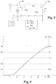
- the picture 3 and Table 1 below correlates, for a constant flow rate of the Booster pump, the power consumed by the Booster pump and the high pressure pump, the flow rate of the high pressure pump (equal to the flow rate of permeate), and the pressure in the filtration units. It appears that the conversion rate is directly related to the available power supplied by the renewable energy source.
- the control method can also include a shutdown mode of the installation in which the high pressure, booster and low pressure pumps are successively shut down as soon as the power supplied by the supply means becomes lower than the set value P HP0 .
- all of the pumps are shut down as soon as the available power supplied by the renewable energy source no longer makes it possible to produce permeate.
- the installation also includes a bypass fitted with a pressure regulation valve allowing the concentrate evacuation line to short-circuit the energy recovery units, it is advantageous to control the opening gradual (for example at 0.5 l/second) of the pressure regulation valve 20 so that the decrease in the osmotic pressure in the filtration units remains less than 1 bar/s, preferably less than 0.5 bar/ s, and this, to remain within the limits set by the manufacturers.
- the pressure in the filtration units remains high, ie of the order of the osmotic pressure (30 bars).
- the permeate from the freshwater treatment and storage units is re-sucked into the filtration units.
- the reintroduced permeate then drives out the concentrate which is evacuated through the evacuation line 25 towards the discharges via the bypass 26. Thanks to the non-return valves 8 and 9, the concentrate cannot rise upstream and is forced to take the evacuation line 25.
- control method according to the invention further comprises a maintenance mode for the installation which consists of a backwashing by the permeates, and which intervenes automatically as soon as the pumps stop.
- This spontaneous circulation because it is induced by the osmotic pressure, allows the permeate to fill the membranes with fresh water in order to condition them during the stoppage of the installation.
- the Booster pump when starting the low-pressure pump, the latter is slaved according to the MPPT protocol so as to take advantage of the power supplied by the renewable energy source, insofar as it alone operates.
- the Booster pump is started with an MPPT type search to reach a flow set point value.
- the high pressure pump is started, the operating speeds of the Booster pump and the low pressure pump are adjusted to the needs of the high pressure pump.
- the search for the MPPT moves from the low pressure pump to the Booster pump and then to the high pressure pump.
- the installation control cycle takes place as follows and as illustrated in picture 3 .
- the low pressure pump and the booster pump start up, the flow rate of the booster pump being assigned for example to a value of 5 m3/hour.
- the high pressure pump starts and follows the increase in the incident power (passing for example through a value of 1 m3 /hour, then 2 m3/hour, to reach 2.5 m3/hour).
- the permeate flow rate increases through a value of 1 m3/hour, then 2 m3/hour, to reach 2.5 m3/hour.
- the conversion rate T (defined by: Q 24 / (Q 13 + Q 7 )) follows an increase passing through a value of 20%, then 29% to reach 38%.
- the flow rate curves are reversed, as is the conversion rate.
- the power P ⁇ becomes less than 1.5 kW, for example, the high pressure pump stops, the low pressure and Booster pumps continue to operate for a defined period to allow the replacement of high salinity concentrates by water sea with lower salinity. This phase allows the washing of the membranes with the concentrate which has become sea water, therefore with low salinity.
- the installation piloting cycle takes place in a similar manner depending on the force of the wind.
- the desalination installation further comprises a pressure accumulator 28 tapped on the seawater supply line 21, between the high-pressure pump 7 and the filtration units 12a, 12b.
- the accumulator is able to compensate for variations in pressure at the outlet of the high pressure pump 7.
- the pressure accumulator has the function of storing seawater conveyed by line 21 and the high-pressure pump, at a certain pressure and discharging it into line 21 in the direction of the filtration units at this same pressure when the operation of the high pressure pump 7 flexes, that is to say when the pressure of the sea water from the high pressure pump 7 decreases.
- the accumulator 28 makes it possible to dampen and smooth the pressure variations in the line 21 which supplies the filtration units. In particular, it makes it possible to obtain variation ramps of less than 0.5 bars/sec. Thus, the mechanical strength of the membranes is preserved.
- the pressure accumulator 28 is a tubular enclosure 282 communicating with the line 21 and containing a volume of nitrogen contained in an envelope at an initial pressure close to the osmotic pressure corresponding to the salinity of sea water, for example of 28 bar.
- the pressure of the nitrogen contained in the envelope is the osmotic pressure corresponding to the salinity of sea water.
- tubular enclosure 28 (with a capacity of around 120 l) as well as the casing 284 and define the initial inflation pressure, so that the pressure in the casing varies by example between 28 and 60 bars.
- the latter may be in the form of a rubber casing, the ends of which are wedged at the two ends 285, 285' of the tubular enclosure by means of a plug 280, 280' respectively, and this, in a watertight manner. means of O-rings 281, 281'.
- the pressure accumulator can be the subject of other embodiments. It may comprise a steel or composite tube, and fitted with a sliding piston hermetically separating an enclosure containing a volume of nitrogen and an enclosure connected to line 21.
- the installation according to the invention operates with low to medium conversion rates, overall less than 45%.
- This characteristic makes it possible to reduce the energy consumption of the membranes and also makes it possible to reject concentrate of low salinity, of the order of 45g to 50g/litre, whereas the known installations commonly reject concentrate having a salinity of the order of 90g /liter.
- the environmental impact is therefore less, and this constitutes a real advantage of the invention.
- the installation allows, when the power of the incident energy is low, operation at zero conversion rate. Under these conditions, the installation allows sweeping of the clogging formed on the membranes with low salinity seawater. Indeed it is sea water which then circulates in the membranes, via the Booster pump. These operating conditions, in addition to the backwash performed when the installation is shut down, contribute to increasing the life of the membranes.
Landscapes
- Chemical & Material Sciences (AREA)
- Engineering & Computer Science (AREA)
- Water Supply & Treatment (AREA)
- Nanotechnology (AREA)
- Chemical Kinetics & Catalysis (AREA)
- Life Sciences & Earth Sciences (AREA)
- Hydrology & Water Resources (AREA)
- Environmental & Geological Engineering (AREA)
- Organic Chemistry (AREA)
- Separation Using Semi-Permeable Membranes (AREA)
Claims (16)
- Verfahren zur Steuerung einer Entsalzungsanlage, welche mindestens aufweist:- eine Leitung (21) zum Zuführen von Meerwasser zu mindestens einer Filterungseinheit, die mit tangentialen Umkehrosmose-Filtermembranen (12, 12a, 12b) versehen ist, wobei die Zuführleitung ausgehend von ihrem Einlass (E) nacheinander mit einer ersten Niederdruckpumpe (1) und einer zweiten Hochdruckpumpe (7) versehen ist, deren Fördermenge proportional zur Drehgeschwindigkeit ist,- eine Leitung (24) zum Abführen von aus den Membranen austretendem Permeat zu einer Süßwasserbehandlungs- und -speichereinheit (15, 16),- eine Leitung (25) zum Abführen von Konzentrat,- ein Kreis (22), der von der Zuführleitung (21) stromaufwärts und stromabwärts der Hochdruckpumpe abzweigt, wobei der Kreis eine Energierückgewinnungseinheit passiert, welche mit einem Drucktauscher (14) und einer als "Booster" bezeichneten Pumpe (13) versehen ist, wobei der Kreis ebenfalls mit der Leitung (25) zum Abführen von Konzentrat verbunden ist, wobei die Abführleitung den Drucktauscher (14) passiert,- Einrichtungen (23) zur Versorgung mit aus einer regenerierbaren Energiequelle kommendem Strom und zum Versorgen der Niederdruckpumpe, der Hochdruckpumpe und der Booster-Pumpe mit variablen Leistungen, wobei die Versorgungseinrichtungen (23) einen Photovoltaikgenerator (23g) aufweisen, der die Niederdruckpumpe, die Booster-Pumpe und die Hochdruckpumpe jeweils mittels eines ersten (23a), eines zweiten (23b) bzw. eines dritten (23c) Leistungswandlers (23) mit variabler Frequenz speist, wobei die Leistungswandler nach einem MPPT-Protokoll (Maximum Power Point Tracking) gesteuert werden,dadurch gekennzeichnet, dass das Steuerverfahren mindestens eine Betriebsart aufweist, in welcher:- die Fördermenge Q25 in der Leitung (25) zum Abführen von Konzentrat während dessen Übergang in die Energierückgewinnungseinheit auf einem Wert gehalten wird, der im Wesentlichen gleich (die Differenz zwischen den Fördermengen übersteigt 5% nicht) demjenigen der Fördermenge Q13 der Booster-Pumpe ist, welcher seinerseits über einem Schwellenwert Q13min gehalten wird, welcher der Mindestfördermenge Q12min entspricht, die für den Betrieb der Filtrierungseinheiten erforderlich ist,- der Druck am Ausgang der Booster-Pumpe auf einem Wert gehalten wird, der gleich demjenigen des Drucks am Ausgang der Hochdruckpumpe (7) ist,- die Fördermenge Q7 der Hochdruckpumpe von der Frequenz und der Leistung des von den Versorgungseinrichtungen zugeführten Stroms ist,derart, dass die Fördermenge Q24 an Permeat am Ausgang der mindestens einen Filtrierungseinheit (12, 12a, 12b) im Wesentlichen (die Differenz zwischen den Fördermengen übersteigt 5% nicht) gleich der Fördermenge Q7 der Hochdruckpumpe ist.
- Steuerverfahren nach Anspruch 1, dadurch gekennzeichnet, dass das Steuerverfahren einen ersten Modus des Startens der Anlage aufweist, welcher das nacheinander erfolgende Anfahren der Niederdruckpumpe, der Booster-Pumpe und der Hochdruckpumpe aufweist, sobald die von den Versorgungseinrichtungen (23) zugeführte Leistung einen Sollwert PHP0 übersteigt.
- Steuerverfahren nach Anspruch 1 oder 2, dadurch gekennzeichnet, dass die Umwandlungsrate, die durch den Quotienten aus der Permeatfördermenge und der Summe der Fördermenge des Hochdruckpumpe und der Fördermenge der Booster-Pumpe definiert ist, geringer als 40% bleibt, so dass der Wirkungsgrad der Membranen optimiert ist, und der Salzgehalt der Konzentrate gering bleibt.
- Steuerverfahren nach einem der vorhergehenden Ansprüche, und bei welchem die Anlage ferner einen Bypass (26) aufweist, der mit einem Druckregelventil (20) versehen ist, welches ein Umgehen der Leitung (25) zum Abführen von Konzentrat ermöglicht, dadurch gekennzeichnet, dass beim Starten der Hochdruckpumpe das progressive Schließen des Druckregelventils derart gesteuert wird, dass die Erhöhung des die Filterungseinheiten passierenden Drucks unter 1 bar/s, vorzugsweise 0,5 bar/s, bleibt.
- Steuerverfahren nach einem der vorhergehenden Ansprüche, dadurch gekennzeichnet, dass die Fördermenge am Ausgang der Booster-Pumpe im Betriebsmodus auf einem konstanten Wert gehalten wird.
- Steuerverfahren nach einem der Ansprüche 1 bis 4, dadurch gekennzeichnet, dass die Fördermenge am Ausgang der Booster-Pumpe im Betriebsmodus stufenweise oder kontinuierlich durch die Fördermenge der Hochdruckpumpe geregelt wird.
- Steuerverfahren nach einem der vorhergehenden Ansprüche, dadurch gekennzeichnet, dass es mindestens einen Anlagenstoppmodus aufweist, bei welchem die Hochdruckpumpe, die Booster-Pumpe und die Niederdruckpumpe nacheinander gestoppt werden, sobald die von den Versorgungseinrichtungen (23) zugeführte Leistung unter einen Sollwert PHP0 fällt.
- Steuerverfahren nach dem vorhergehenden Anspruch, und bei welchem die Anlage ferner einen Bypass (26) aufweist, der mit einem Druckregelventil (20) versehen ist, welches der Leitung (25) zum Abführen des Konzentrats ermöglicht, die Leitung zum Abführen des Konzentrats (25) zu umgehen, dadurch gekennzeichnet, dass der Anlagenstoppmodus das progressive Öffnen des Druckregelventils aufweist, derart, dass unter der Wirkung des osmotischen Drucks, aus den Süßwasserbehandlungs- und -speichereinheiten (15, 16) kommendes Permeat in die Filterungseinheiten angesaugt wird, um das Konzentrat über den Bypass (26) zu den Abfällen auszutreiben und die Membranen mit Süßwasser zu konditionieren.
- Steuerverfahren nach dem vorhergehenden Anspruch, dadurch gekennzeichnet, dass das progressive Öffnen des Druckregelventils derart gesteuert wird, das die Verringerung des Drucks in den Filterungseinheiten unter 1 bar/s, vorzugsweise 0,5 bar/s, bleibt.
- Steuerverfahren nach einem der Ansprüche 1 bis 9, dadurch gekennzeichnet, dass die Fördermenge an Permeaten und der Umwandlungsgrad sich kontinuierlich und parallel zwischen null und einem Maximalwert entwickeln, und dies in Abhängigkeit von der durch die Stromversorgungseinrichtungen (23) gelieferten Leistung.
- Steuerverfahren nach einem der Ansprüche 1 bis 10, dadurch gekennzeichnet, dass die Entsalzungsanlage ferner einen Druckspeicher (28) aufweist, der zwischen der Hochdruckpumpe (7) und der Filterungseinheit (12, 12a, 12b) von der Meerwasserzufuhrleitung (21) abgezweigt ist, wobei der Speicher in der Lage ist, die Druckschwankungen am Ausgang der Hochdruckpumpe (7) gemäß Schwankungsrampen von weniger als 0,5 bar/sec zu kompensieren.
- Entsalzungsanlage, welche mindestens aufweist:- eine Leitung (21) zum Zuführen von Meerwasser zu mindestens einer Filterungseinheit, die mit tangentialen Umkehrosmose-Filtermembranen (12, 12a, 12b) versehen ist, wobei die Zuführleitung ausgehend von ihrem Einlass (E) nacheinander mit einer ersten Niederdruckpumpe (1) und einer zweiten Hochdruckpumpe (7) versehen ist, deren Fördermenge von der Frequenz und der Leistung des von den Versorgungseinrichtungen gelieferten Stroms abhängig ist und vorzugsweise proportional zur Frequenz und zur Leistung des von den Versorgungseinrichtungen gelieferten Stroms ist,- eine Leitung (24) zum Abführen von aus den Membranen austretendem Permeat zu einer Süßwasserbehandlungs- und -speichereinheit (15, 16),- eine Leitung (25) zum Abführen von Konzentrat,- ein Kreis (22), der von der Zuführleitung (21) stromaufwärts und stromabwärts der Hochdruckpumpe abzweigt, wobei der Kreis eine Energierückgewinnungseinheit passiert, welche mit einem Drucktauscher (14) und einer als "Booster" bezeichneten Pumpe (13) versehen ist, wobei der Kreis ebenfalls mit der Leitung (25) zum Abführen von Konzentrat verbunden ist, wobei die Abführleitung den Drucktauscher (14) passiert,- Einrichtungen (23) zur Versorgung mit aus einer regenerierbaren Energiequelle kommendem Strom und zum Versorgen der Niederdruckpumpe, der Hochdruckpumpe und der Booster-Pumpe mit variablen Frequenzen und Leistungen,wobei die Versorgungseinrichtungen (23) einen Photovoltaikgenerator (23g) aufweisen, der die Niederdruckpumpe, die Booster-Pumpe und die Hochdruckpumpe jeweils mittels eines ersten (23a), eines zweiten (23b) bzw. eines dritten Leistungswandlers (23) mit variabler Frequenz speist, wobei die Leistungswandler nach einem MPPT-Protokoll (Maximum Power Point Tracking) gesteuert werden.wobei die Entsalzungsanlage einen Bypass (26) aufweist, der mit einem Druckregelventil (20) versehen ist, welches der Leitung (25) zum Abführen des Konzentrats die Energierückgewinnungseinrichtungen zu umgehen.
- Entsalzungsanlage nach Anspruch 12, dadurch gekennzeichnet, dass die Meerwasserzufuhrleitung stromabwärts der Niederdruckpumpe (1) und stromaufwärts des stromaufwärts der Hochdruckpumpe befindlichen Abzweigs von dem Kreis einen Vorbehandlungsblock (2) aufweist, dem ein Vorfilter (3) folgt, welchem seinerseits ein Entlüfter (4) folgt.
- Entsalzungsanlage nach einem der Ansprüche 12 bis 13, dadurch gekennzeichnet, dass die Hochdruckpumpe eine Verdrängerpumpe ist.
- Entsalzungsanlage nach einem der Ansprüche 12 bis 14, dadurch gekennzeichnet, dass die Entsalzungsanlage ferner einen Druckspeicher (28) aufweist, der zwischen der Hochdruckpumpe (7) und der Filterungseinheit (12, 12a, 12b) von der Meerwasserzufuhrleitung (21) abgezweigt ist, wobei der Speicher in der Lage ist, den Druckabfall am Ausgang der Hochdruckpumpe (7) zu kompensieren.
- Entsalzungsanlage nach Anspruch 15, dadurch gekennzeichnet, dass der Drucksammler (28) ein rohrförmiger Behälter (282) ist, der mit der Leitung (21) in Verbindung steht und ein Stickstoffvolumen enthält, das in einem Gehäuse (284) bei einem Ausgangsdruck nahe dem osmotischen Druck, der dem Salzgehalt des Meerwassers, beispielsweise 28 bar, entspricht, enthalten ist.
Applications Claiming Priority (2)
| Application Number | Priority Date | Filing Date | Title |
|---|---|---|---|
| FR1556236A FR3038311B1 (fr) | 2015-07-02 | 2015-07-02 | Procede de pilotage d'une installation de dessalement alimentee par une source d'energie renouvelable et installation associee |
| PCT/IB2016/053869 WO2017002022A1 (fr) | 2015-07-02 | 2016-06-29 | Procede de pilotage d'une installation de dessalement alimentee par une source d' energie renouvelable et installation associee |
Publications (3)
| Publication Number | Publication Date |
|---|---|
| EP3317229A1 EP3317229A1 (de) | 2018-05-09 |
| EP3317229B1 EP3317229B1 (de) | 2020-01-29 |
| EP3317229B2 true EP3317229B2 (de) | 2022-11-09 |
Family
ID=53801099
Family Applications (1)
| Application Number | Title | Priority Date | Filing Date |
|---|---|---|---|
| EP16736248.2A Active EP3317229B2 (de) | 2015-07-02 | 2016-06-29 | Verfahren zur steuerung einer von einer erneuerbaren energiequelle gespeisten entsalzungsanlage und zugehörige anlage |
Country Status (7)
| Country | Link |
|---|---|
| EP (1) | EP3317229B2 (de) |
| JP (1) | JP2018519158A (de) |
| AU (1) | AU2016286651A1 (de) |
| ES (1) | ES2785572T5 (de) |
| FR (1) | FR3038311B1 (de) |
| WO (1) | WO2017002022A1 (de) |
| ZA (1) | ZA201800011B (de) |
Families Citing this family (4)
| Publication number | Priority date | Publication date | Assignee | Title |
|---|---|---|---|---|
| CN108128850B (zh) * | 2018-01-18 | 2018-12-25 | 盐城国睿信科技有限公司 | 一种风能海水淡化装置 |
| US10308524B1 (en) * | 2019-01-15 | 2019-06-04 | Kuwait Institute For Scientific Research | Pressure-reduced saline water treatment system |
| IL280816B2 (en) * | 2019-02-07 | 2024-05-01 | Synauta Inc | Water treatment methods and apparatus |
| KR102856055B1 (ko) * | 2019-09-23 | 2025-09-04 | 코웨이 주식회사 | 정수기 |
Family Cites Families (22)
| Publication number | Priority date | Publication date | Assignee | Title |
|---|---|---|---|---|
| FR1556236A (de) | 1966-10-31 | 1969-02-07 | ||
| JPS5496485A (en) * | 1978-01-17 | 1979-07-30 | Yasuhiro Sakaguchi | Membrane water production method and its manufacture apparatus |
| JP2004041888A (ja) * | 2002-07-10 | 2004-02-12 | Mitsubishi Heavy Ind Ltd | 逆浸透膜装置及びその運転方法 |
| ES2277509B1 (es) | 2005-04-05 | 2008-06-01 | Empresa Mixta De Aguas De Las Palmas, S.A. | Desaladoras de osmosis inversa independientes conectadas energicamente. |
| US20070029255A1 (en) | 2005-08-03 | 2007-02-08 | D Amato Fernando J | Desalination system powered by renewable energy source and methods related thereto |
| GR1005796B (el) | 2006-02-24 | 2008-01-30 | Συστημα ανακτησης ενεργειας και μειωσης των επικαθισεων στις μεμβρανες σε μοναδα αφαλατωσης (μεταβλητης ισχυος και παροχης) με αντιστροφη οσμωση | |
| WO2007118235A2 (en) * | 2006-04-07 | 2007-10-18 | Nxstage Medical Inc. | Filtration system for preparation of fluids for medical applications. |
| FR2933969B1 (fr) | 2008-07-21 | 2011-11-11 | Degremont | Installation de dessalement d'eau par osmose inverse |
| JP2010089036A (ja) * | 2008-10-09 | 2010-04-22 | Ebara Corp | 膜分離装置、膜分離装置の運転管理方法 |
| US20110006005A1 (en) * | 2009-05-18 | 2011-01-13 | Aquamarine Power Limited | Desalination system and method |
| DE102010009581A1 (de) | 2010-02-26 | 2011-09-01 | Danfoss A/S | Umkehrosmosevorrichtung |
| US20120061300A1 (en) * | 2010-09-15 | 2012-03-15 | Takeshi Matsushiro | Membrane filtration system |
| US20120211409A1 (en) | 2011-02-23 | 2012-08-23 | Massachusetts Institute Of Technology | Photovoltaic reverse osmosis system with thermal management |
| DE102011115057A1 (de) | 2011-10-07 | 2013-04-11 | Robert Bosch Gmbh | Wasseraufbereitungsanlage, Anordnung mit Wasseraufbereitungsanlage und Stromerzeugungseinrichtung sowie zugehöriges Betreibsverfahren |
| CN202358969U (zh) * | 2011-11-15 | 2012-08-01 | 杭州水处理技术研究开发中心有限公司 | 一种风力发电反渗透淡化装置 |
| CN202808493U (zh) * | 2012-07-17 | 2013-03-20 | 浙江艾波特环保科技股份有限公司 | 一种可变流量的太阳能海水淡化装置 |
| CN103626261B (zh) | 2012-10-19 | 2014-12-17 | 深圳市天源新能源有限公司 | 一种光伏海水淡化系统及控制方法和光伏海水淡化逆变器 |
| WO2014133101A1 (ja) * | 2013-02-28 | 2014-09-04 | 東レ株式会社 | 脱塩水の製造方法 |
| DE102013218965A1 (de) * | 2013-09-20 | 2015-03-26 | Ksb Aktiengesellschaft | Membrantrennverfahren |
| CN203593678U (zh) * | 2013-12-17 | 2014-05-14 | 中国电力工程顾问集团公司 | 一种热膜耦合海水淡化系统 |
| CN103964549A (zh) * | 2014-05-24 | 2014-08-06 | 哈尔滨锅炉厂有限责任公司 | 利用非并网风电的膜法海水淡化系统及其海水淡化方法 |
| WO2016050781A1 (en) | 2014-09-30 | 2016-04-07 | Megacivic S.R.L. | Desalination plant powered by renewable energy |
-
2015
- 2015-07-02 FR FR1556236A patent/FR3038311B1/fr active Active
-
2016
- 2016-06-29 ES ES16736248T patent/ES2785572T5/es active Active
- 2016-06-29 WO PCT/IB2016/053869 patent/WO2017002022A1/fr not_active Ceased
- 2016-06-29 JP JP2017568405A patent/JP2018519158A/ja active Pending
- 2016-06-29 AU AU2016286651A patent/AU2016286651A1/en not_active Abandoned
- 2016-06-29 EP EP16736248.2A patent/EP3317229B2/de active Active
-
2018
- 2018-01-02 ZA ZA2018/00011A patent/ZA201800011B/en unknown
Also Published As
| Publication number | Publication date |
|---|---|
| ZA201800011B (en) | 2018-12-19 |
| EP3317229B1 (de) | 2020-01-29 |
| JP2018519158A (ja) | 2018-07-19 |
| EP3317229A1 (de) | 2018-05-09 |
| ES2785572T5 (es) | 2023-03-23 |
| AU2016286651A1 (en) | 2018-01-25 |
| FR3038311A1 (fr) | 2017-01-06 |
| ES2785572T3 (es) | 2020-10-07 |
| FR3038311B1 (fr) | 2019-05-31 |
| WO2017002022A1 (fr) | 2017-01-05 |
Similar Documents
| Publication | Publication Date | Title |
|---|---|---|
| JP5085675B2 (ja) | 海水淡水化システム | |
| JP5991200B2 (ja) | 濃度差発電装置とその運転方法 | |
| EP2234701B1 (de) | Umkehrosmose-system mit batchbetrieb | |
| JP4751325B2 (ja) | 単一の容器における可変圧による連続的な閉回路の脱塩のための装置 | |
| EP3317229B2 (de) | Verfahren zur steuerung einer von einer erneuerbaren energiequelle gespeisten entsalzungsanlage und zugehörige anlage | |
| AU2010274473B2 (en) | Water producing system | |
| US20110056878A1 (en) | Membrane filtration system | |
| US20080105617A1 (en) | Two pass reverse osmosis system | |
| FR2852310A1 (fr) | Procede et systeme de purification d'eau, ainsi que module pour un tel systeme | |
| SG177313A1 (en) | Filtering method, and membrane-filtering apparatus | |
| EP2981670A2 (de) | Herstellung von injektionswasser durch kopplung von direktosmoseverfahren mit anderen filtrationsverfahren | |
| JP5538572B2 (ja) | 海水淡水化装置 | |
| WO2010073194A1 (fr) | Procede et installation pour la gestion du colmatage de modules membranaires et de membranes de filtration | |
| FR2995540A1 (fr) | Unite sous-marine de traitement de l'eau et procede de nettoyage de ladite unite | |
| AU2009341904A1 (en) | Water desalination equipment and cleaning method for water desalination equipment | |
| JP2000093751A (ja) | 逆浸透分離装置及び逆浸透分離方法 | |
| FR2487810A1 (fr) | Installation pour la deshydratation des boues comportant plusieurs filtres-presses montes en parallele | |
| WO2020239707A1 (fr) | Installation de filtration membranaire de liquides et procede de production d'eau potable avec celle-ci sans post-mineralisation | |
| JP2016097331A (ja) | 造水システムおよび造水方法 | |
| JP6269486B2 (ja) | 脱塩水の製造方法 | |
| JP2001137848A (ja) | 水処理装置および造水方法 | |
| JP3375070B2 (ja) | 膜処理装置および造水方法 | |
| FR2924952A1 (fr) | Systeme de potabilisation d'eau,par energie renouvelable et filtration sur membrane | |
| JP2014034005A (ja) | 塩水淡水化装置および造水方法 | |
| WO2021047965A1 (fr) | Procede et systeme de dessalement avec une etape d'osmose retardee et une etape d'osmose inverse |
Legal Events
| Date | Code | Title | Description |
|---|---|---|---|
| STAA | Information on the status of an ep patent application or granted ep patent |
Free format text: STATUS: THE INTERNATIONAL PUBLICATION HAS BEEN MADE |
|
| PUAI | Public reference made under article 153(3) epc to a published international application that has entered the european phase |
Free format text: ORIGINAL CODE: 0009012 |
|
| STAA | Information on the status of an ep patent application or granted ep patent |
Free format text: STATUS: REQUEST FOR EXAMINATION WAS MADE |
|
| 17P | Request for examination filed |
Effective date: 20171222 |
|
| AK | Designated contracting states |
Kind code of ref document: A1 Designated state(s): AL AT BE BG CH CY CZ DE DK EE ES FI FR GB GR HR HU IE IS IT LI LT LU LV MC MK MT NL NO PL PT RO RS SE SI SK SM TR |
|
| AX | Request for extension of the european patent |
Extension state: BA ME |
|
| DAX | Request for extension of the european patent (deleted) | ||
| RAV | Requested validation state of the european patent: fee paid |
Extension state: MA Effective date: 20180222 |
|
| STAA | Information on the status of an ep patent application or granted ep patent |
Free format text: STATUS: EXAMINATION IS IN PROGRESS |
|
| 17Q | First examination report despatched |
Effective date: 20181106 |
|
| GRAP | Despatch of communication of intention to grant a patent |
Free format text: ORIGINAL CODE: EPIDOSNIGR1 |
|
| STAA | Information on the status of an ep patent application or granted ep patent |
Free format text: STATUS: GRANT OF PATENT IS INTENDED |
|
| INTG | Intention to grant announced |
Effective date: 20190904 |
|
| GRAS | Grant fee paid |
Free format text: ORIGINAL CODE: EPIDOSNIGR3 |
|
| GRAA | (expected) grant |
Free format text: ORIGINAL CODE: 0009210 |
|
| STAA | Information on the status of an ep patent application or granted ep patent |
Free format text: STATUS: THE PATENT HAS BEEN GRANTED |
|
| AK | Designated contracting states |
Kind code of ref document: B1 Designated state(s): AL AT BE BG CH CY CZ DE DK EE ES FI FR GB GR HR HU IE IS IT LI LT LU LV MC MK MT NL NO PL PT RO RS SE SI SK SM TR |
|
| REG | Reference to a national code |
Ref country code: GB Ref legal event code: FG4D Free format text: NOT ENGLISH |
|
| REG | Reference to a national code |
Ref country code: CH Ref legal event code: EP |
|
| REG | Reference to a national code |
Ref country code: AT Ref legal event code: REF Ref document number: 1228400 Country of ref document: AT Kind code of ref document: T Effective date: 20200215 |
|
| REG | Reference to a national code |
Ref country code: IE Ref legal event code: FG4D Free format text: LANGUAGE OF EP DOCUMENT: FRENCH |
|
| REG | Reference to a national code |
Ref country code: DE Ref legal event code: R096 Ref document number: 602016028730 Country of ref document: DE |
|
| REG | Reference to a national code |
Ref country code: CH Ref legal event code: NV Representative=s name: DENNEMEYER AG, CH |
|
| REG | Reference to a national code |
Ref country code: GR Ref legal event code: EP Ref document number: 20200401063 Country of ref document: GR Effective date: 20200615 |
|
| REG | Reference to a national code |
Ref country code: NL Ref legal event code: MP Effective date: 20200129 |
|
| PG25 | Lapsed in a contracting state [announced via postgrant information from national office to epo] |
Ref country code: NO Free format text: LAPSE BECAUSE OF FAILURE TO SUBMIT A TRANSLATION OF THE DESCRIPTION OR TO PAY THE FEE WITHIN THE PRESCRIBED TIME-LIMIT Effective date: 20200429 Ref country code: PT Free format text: LAPSE BECAUSE OF FAILURE TO SUBMIT A TRANSLATION OF THE DESCRIPTION OR TO PAY THE FEE WITHIN THE PRESCRIBED TIME-LIMIT Effective date: 20200621 Ref country code: FI Free format text: LAPSE BECAUSE OF FAILURE TO SUBMIT A TRANSLATION OF THE DESCRIPTION OR TO PAY THE FEE WITHIN THE PRESCRIBED TIME-LIMIT Effective date: 20200129 Ref country code: RS Free format text: LAPSE BECAUSE OF FAILURE TO SUBMIT A TRANSLATION OF THE DESCRIPTION OR TO PAY THE FEE WITHIN THE PRESCRIBED TIME-LIMIT Effective date: 20200129 |
|
| REG | Reference to a national code |
Ref country code: LT Ref legal event code: MG4D |
|
| PG25 | Lapsed in a contracting state [announced via postgrant information from national office to epo] |
Ref country code: BG Free format text: LAPSE BECAUSE OF FAILURE TO SUBMIT A TRANSLATION OF THE DESCRIPTION OR TO PAY THE FEE WITHIN THE PRESCRIBED TIME-LIMIT Effective date: 20200429 Ref country code: IS Free format text: LAPSE BECAUSE OF FAILURE TO SUBMIT A TRANSLATION OF THE DESCRIPTION OR TO PAY THE FEE WITHIN THE PRESCRIBED TIME-LIMIT Effective date: 20200529 Ref country code: HR Free format text: LAPSE BECAUSE OF FAILURE TO SUBMIT A TRANSLATION OF THE DESCRIPTION OR TO PAY THE FEE WITHIN THE PRESCRIBED TIME-LIMIT Effective date: 20200129 Ref country code: SE Free format text: LAPSE BECAUSE OF FAILURE TO SUBMIT A TRANSLATION OF THE DESCRIPTION OR TO PAY THE FEE WITHIN THE PRESCRIBED TIME-LIMIT Effective date: 20200129 Ref country code: LV Free format text: LAPSE BECAUSE OF FAILURE TO SUBMIT A TRANSLATION OF THE DESCRIPTION OR TO PAY THE FEE WITHIN THE PRESCRIBED TIME-LIMIT Effective date: 20200129 |
|
| PG25 | Lapsed in a contracting state [announced via postgrant information from national office to epo] |
Ref country code: NL Free format text: LAPSE BECAUSE OF FAILURE TO SUBMIT A TRANSLATION OF THE DESCRIPTION OR TO PAY THE FEE WITHIN THE PRESCRIBED TIME-LIMIT Effective date: 20200129 |
|
| REG | Reference to a national code |
Ref country code: ES Ref legal event code: FG2A Ref document number: 2785572 Country of ref document: ES Kind code of ref document: T3 Effective date: 20201007 |
|
| REG | Reference to a national code |
Ref country code: DE Ref legal event code: R026 Ref document number: 602016028730 Country of ref document: DE |
|
| PG25 | Lapsed in a contracting state [announced via postgrant information from national office to epo] |
Ref country code: LT Free format text: LAPSE BECAUSE OF FAILURE TO SUBMIT A TRANSLATION OF THE DESCRIPTION OR TO PAY THE FEE WITHIN THE PRESCRIBED TIME-LIMIT Effective date: 20200129 Ref country code: RO Free format text: LAPSE BECAUSE OF FAILURE TO SUBMIT A TRANSLATION OF THE DESCRIPTION OR TO PAY THE FEE WITHIN THE PRESCRIBED TIME-LIMIT Effective date: 20200129 Ref country code: CZ Free format text: LAPSE BECAUSE OF FAILURE TO SUBMIT A TRANSLATION OF THE DESCRIPTION OR TO PAY THE FEE WITHIN THE PRESCRIBED TIME-LIMIT Effective date: 20200129 Ref country code: SK Free format text: LAPSE BECAUSE OF FAILURE TO SUBMIT A TRANSLATION OF THE DESCRIPTION OR TO PAY THE FEE WITHIN THE PRESCRIBED TIME-LIMIT Effective date: 20200129 Ref country code: SM Free format text: LAPSE BECAUSE OF FAILURE TO SUBMIT A TRANSLATION OF THE DESCRIPTION OR TO PAY THE FEE WITHIN THE PRESCRIBED TIME-LIMIT Effective date: 20200129 Ref country code: EE Free format text: LAPSE BECAUSE OF FAILURE TO SUBMIT A TRANSLATION OF THE DESCRIPTION OR TO PAY THE FEE WITHIN THE PRESCRIBED TIME-LIMIT Effective date: 20200129 Ref country code: DK Free format text: LAPSE BECAUSE OF FAILURE TO SUBMIT A TRANSLATION OF THE DESCRIPTION OR TO PAY THE FEE WITHIN THE PRESCRIBED TIME-LIMIT Effective date: 20200129 |
|
| PLBI | Opposition filed |
Free format text: ORIGINAL CODE: 0009260 |
|
| REG | Reference to a national code |
Ref country code: AT Ref legal event code: MK05 Ref document number: 1228400 Country of ref document: AT Kind code of ref document: T Effective date: 20200129 |
|
| PLAX | Notice of opposition and request to file observation + time limit sent |
Free format text: ORIGINAL CODE: EPIDOSNOBS2 |
|
| 26 | Opposition filed |
Opponent name: GENIUS WATTER S.R.L. Effective date: 20201029 |
|
| PG25 | Lapsed in a contracting state [announced via postgrant information from national office to epo] |
Ref country code: IT Free format text: LAPSE BECAUSE OF FAILURE TO SUBMIT A TRANSLATION OF THE DESCRIPTION OR TO PAY THE FEE WITHIN THE PRESCRIBED TIME-LIMIT Effective date: 20200129 Ref country code: MC Free format text: LAPSE BECAUSE OF FAILURE TO SUBMIT A TRANSLATION OF THE DESCRIPTION OR TO PAY THE FEE WITHIN THE PRESCRIBED TIME-LIMIT Effective date: 20200129 Ref country code: AT Free format text: LAPSE BECAUSE OF FAILURE TO SUBMIT A TRANSLATION OF THE DESCRIPTION OR TO PAY THE FEE WITHIN THE PRESCRIBED TIME-LIMIT Effective date: 20200129 |
|
| PG25 | Lapsed in a contracting state [announced via postgrant information from national office to epo] |
Ref country code: SI Free format text: LAPSE BECAUSE OF FAILURE TO SUBMIT A TRANSLATION OF THE DESCRIPTION OR TO PAY THE FEE WITHIN THE PRESCRIBED TIME-LIMIT Effective date: 20200129 Ref country code: PL Free format text: LAPSE BECAUSE OF FAILURE TO SUBMIT A TRANSLATION OF THE DESCRIPTION OR TO PAY THE FEE WITHIN THE PRESCRIBED TIME-LIMIT Effective date: 20200129 |
|
| PLBB | Reply of patent proprietor to notice(s) of opposition received |
Free format text: ORIGINAL CODE: EPIDOSNOBS3 |
|
| PG25 | Lapsed in a contracting state [announced via postgrant information from national office to epo] |
Ref country code: LU Free format text: LAPSE BECAUSE OF NON-PAYMENT OF DUE FEES Effective date: 20200629 |
|
| PG25 | Lapsed in a contracting state [announced via postgrant information from national office to epo] |
Ref country code: IE Free format text: LAPSE BECAUSE OF NON-PAYMENT OF DUE FEES Effective date: 20200629 |
|
| VS25 | Lapsed in a validation state [announced via postgrant information from nat. office to epo] |
Ref country code: MA Free format text: LAPSE BECAUSE OF FAILURE TO SUBMIT A TRANSLATION OF THE DESCRIPTION OR TO PAY THE FEE WITHIN THE PRESCRIBED TIME-LIMIT Effective date: 20200129 |
|
| PG25 | Lapsed in a contracting state [announced via postgrant information from national office to epo] |
Ref country code: TR Free format text: LAPSE BECAUSE OF FAILURE TO SUBMIT A TRANSLATION OF THE DESCRIPTION OR TO PAY THE FEE WITHIN THE PRESCRIBED TIME-LIMIT Effective date: 20200129 Ref country code: MT Free format text: LAPSE BECAUSE OF FAILURE TO SUBMIT A TRANSLATION OF THE DESCRIPTION OR TO PAY THE FEE WITHIN THE PRESCRIBED TIME-LIMIT Effective date: 20200129 Ref country code: CY Free format text: LAPSE BECAUSE OF FAILURE TO SUBMIT A TRANSLATION OF THE DESCRIPTION OR TO PAY THE FEE WITHIN THE PRESCRIBED TIME-LIMIT Effective date: 20200129 |
|
| PG25 | Lapsed in a contracting state [announced via postgrant information from national office to epo] |
Ref country code: MK Free format text: LAPSE BECAUSE OF FAILURE TO SUBMIT A TRANSLATION OF THE DESCRIPTION OR TO PAY THE FEE WITHIN THE PRESCRIBED TIME-LIMIT Effective date: 20200129 Ref country code: AL Free format text: LAPSE BECAUSE OF FAILURE TO SUBMIT A TRANSLATION OF THE DESCRIPTION OR TO PAY THE FEE WITHIN THE PRESCRIBED TIME-LIMIT Effective date: 20200129 |
|
| PUAH | Patent maintained in amended form |
Free format text: ORIGINAL CODE: 0009272 |
|
| STAA | Information on the status of an ep patent application or granted ep patent |
Free format text: STATUS: PATENT MAINTAINED AS AMENDED |
|
| 27A | Patent maintained in amended form |
Effective date: 20221109 |
|
| AK | Designated contracting states |
Kind code of ref document: B2 Designated state(s): AL AT BE BG CH CY CZ DE DK EE ES FI FR GB GR HR HU IE IS IT LI LT LU LV MC MK MT NL NO PL PT RO RS SE SI SK SM TR |
|
| REG | Reference to a national code |
Ref country code: DE Ref legal event code: R102 Ref document number: 602016028730 Country of ref document: DE |
|
| REG | Reference to a national code |
Ref country code: GR Ref legal event code: EP Ref document number: 20230400166 Country of ref document: GR Effective date: 20230307 |
|
| REG | Reference to a national code |
Ref country code: ES Ref legal event code: DC2A Ref document number: 2785572 Country of ref document: ES Kind code of ref document: T5 Effective date: 20230323 |
|
| P01 | Opt-out of the competence of the unified patent court (upc) registered |
Effective date: 20230515 |
|
| PGFP | Annual fee paid to national office [announced via postgrant information from national office to epo] |
Ref country code: GB Payment date: 20250626 Year of fee payment: 10 |
|
| PGFP | Annual fee paid to national office [announced via postgrant information from national office to epo] |
Ref country code: BE Payment date: 20250630 Year of fee payment: 10 |
|
| PGFP | Annual fee paid to national office [announced via postgrant information from national office to epo] |
Ref country code: FR Payment date: 20250627 Year of fee payment: 10 |
|
| PGFP | Annual fee paid to national office [announced via postgrant information from national office to epo] |
Ref country code: GR Payment date: 20250626 Year of fee payment: 10 |
|
| PGFP | Annual fee paid to national office [announced via postgrant information from national office to epo] |
Ref country code: ES Payment date: 20250828 Year of fee payment: 10 |
|
| PGFP | Annual fee paid to national office [announced via postgrant information from national office to epo] |
Ref country code: DE Payment date: 20250725 Year of fee payment: 10 |
|
| PGFP | Annual fee paid to national office [announced via postgrant information from national office to epo] |
Ref country code: CH Payment date: 20250711 Year of fee payment: 10 |