EP3315697B1 - Geräuschloses schloss für eine kraftfahrzeugtür und/oder einen deckel mit betätigungshebel - Google Patents
Geräuschloses schloss für eine kraftfahrzeugtür und/oder einen deckel mit betätigungshebel Download PDFInfo
- Publication number
- EP3315697B1 EP3315697B1 EP17196555.1A EP17196555A EP3315697B1 EP 3315697 B1 EP3315697 B1 EP 3315697B1 EP 17196555 A EP17196555 A EP 17196555A EP 3315697 B1 EP3315697 B1 EP 3315697B1
- Authority
- EP
- European Patent Office
- Prior art keywords
- actuation lever
- lock
- box
- pawl
- wall
- Prior art date
- Legal status (The legal status is an assumption and is not a legal conclusion. Google has not performed a legal analysis and makes no representation as to the accuracy of the status listed.)
- Not-in-force
Links
Images


Classifications
-
- E—FIXED CONSTRUCTIONS
- E05—LOCKS; KEYS; WINDOW OR DOOR FITTINGS; SAFES
- E05B—LOCKS; ACCESSORIES THEREFOR; HANDCUFFS
- E05B81/00—Power-actuated vehicle locks
- E05B81/12—Power-actuated vehicle locks characterised by the function or purpose of the powered actuators
- E05B81/16—Power-actuated vehicle locks characterised by the function or purpose of the powered actuators operating on locking elements for locking or unlocking action
-
- E—FIXED CONSTRUCTIONS
- E05—LOCKS; KEYS; WINDOW OR DOOR FITTINGS; SAFES
- E05B—LOCKS; ACCESSORIES THEREFOR; HANDCUFFS
- E05B83/00—Vehicle locks specially adapted for particular types of wing or vehicle
- E05B83/16—Locks for luggage compartments, car boot lids or car bonnets
- E05B83/18—Locks for luggage compartments, car boot lids or car bonnets for car boot lids or rear luggage compartments
-
- E—FIXED CONSTRUCTIONS
- E05—LOCKS; KEYS; WINDOW OR DOOR FITTINGS; SAFES
- E05B—LOCKS; ACCESSORIES THEREFOR; HANDCUFFS
- E05B81/00—Power-actuated vehicle locks
- E05B81/02—Power-actuated vehicle locks characterised by the type of actuators used
- E05B81/04—Electrical
- E05B81/06—Electrical using rotary motors
-
- E—FIXED CONSTRUCTIONS
- E05—LOCKS; KEYS; WINDOW OR DOOR FITTINGS; SAFES
- E05B—LOCKS; ACCESSORIES THEREFOR; HANDCUFFS
- E05B77/00—Vehicle locks characterised by special functions or purposes
- E05B77/36—Noise prevention; Anti-rattling means
-
- E—FIXED CONSTRUCTIONS
- E05—LOCKS; KEYS; WINDOW OR DOOR FITTINGS; SAFES
- E05B—LOCKS; ACCESSORIES THEREFOR; HANDCUFFS
- E05B81/00—Power-actuated vehicle locks
- E05B81/12—Power-actuated vehicle locks characterised by the function or purpose of the powered actuators
- E05B81/14—Power-actuated vehicle locks characterised by the function or purpose of the powered actuators operating on bolt detents, e.g. for unlatching the bolt
-
- E—FIXED CONSTRUCTIONS
- E05—LOCKS; KEYS; WINDOW OR DOOR FITTINGS; SAFES
- E05B—LOCKS; ACCESSORIES THEREFOR; HANDCUFFS
- E05B81/00—Power-actuated vehicle locks
- E05B81/24—Power-actuated vehicle locks characterised by constructional features of the actuator or the power transmission
- E05B81/26—Output elements
- E05B81/30—Rotary elements
-
- E—FIXED CONSTRUCTIONS
- E05—LOCKS; KEYS; WINDOW OR DOOR FITTINGS; SAFES
- E05B—LOCKS; ACCESSORIES THEREFOR; HANDCUFFS
- E05B81/00—Power-actuated vehicle locks
- E05B81/24—Power-actuated vehicle locks characterised by constructional features of the actuator or the power transmission
- E05B81/32—Details of the actuator transmission
- E05B81/34—Details of the actuator transmission of geared transmissions
-
- E—FIXED CONSTRUCTIONS
- E05—LOCKS; KEYS; WINDOW OR DOOR FITTINGS; SAFES
- E05B—LOCKS; ACCESSORIES THEREFOR; HANDCUFFS
- E05B81/00—Power-actuated vehicle locks
- E05B81/24—Power-actuated vehicle locks characterised by constructional features of the actuator or the power transmission
- E05B81/32—Details of the actuator transmission
- E05B81/42—Cams
-
- E—FIXED CONSTRUCTIONS
- E05—LOCKS; KEYS; WINDOW OR DOOR FITTINGS; SAFES
- E05B—LOCKS; ACCESSORIES THEREFOR; HANDCUFFS
- E05B81/00—Power-actuated vehicle locks
- E05B81/24—Power-actuated vehicle locks characterised by constructional features of the actuator or the power transmission
- E05B81/32—Details of the actuator transmission
- E05B81/42—Cams
- E05B81/44—Cams in the form of grooves
-
- E—FIXED CONSTRUCTIONS
- E05—LOCKS; KEYS; WINDOW OR DOOR FITTINGS; SAFES
- E05B—LOCKS; ACCESSORIES THEREFOR; HANDCUFFS
- E05B85/00—Details of vehicle locks not provided for in groups E05B77/00 - E05B83/00
- E05B85/02—Lock casings
Definitions
- the present patent application for industrial invention relates to a lock for motor vehicle door and/or lid, in particular for the trunk lid.
- Said locks comprise a closing hook that is engaged in a "U"-shaped pin fixed to the body of the motor vehicle.
- a stop lever commonly known as “pawl”
- pawl is engaged with the closing hook to lock the closing hook and keep it in closing position.
- the pawl is actuated by an electrical motor that actuates gears.
- a type of lock wherein the electrical motor rotates an endless screw that engages in a female screw of a slide that actuates on the pawl.
- the operation of such a lock is not noiseless because of the noise of both the forward travel and the backward travel of the slide generated by the engagement between screw and female screw.
- the purpose of the present invention is to eliminate the drawbacks of the prior art by providing a lock for motor vehicle door and/or lid that is noiseless and reliable.
- Another purpose of the present invention is to provide such a lock for motor vehicle door and/or lid that is not bulky and easy to produce and assemble.
- the lock for motor vehicle door and/or lid according to the invention comprises:
- the actuation lever has a body that is connected to a wall of the box, in such manner to rotate and translate with respect to the wall of the box.
- the actuation lever comprises a follower that protrudes from the body and is engaged in a cam obtained in said wall of the box, wherein the cam defines a closed loop circuit in order to control the movement of the actuation lever.
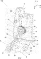
- Fig. 1 With reference to Fig. 1 , reference is made to a set of three Cartesian axes (X, Y, Z).
- the lock (100) comprises a closing hook (2) suitable for fastening a pin (not shown), which generally has a "U"-shape.
- the pin is fixed to the vehicle body. Instead, the lock (100) is disposed in a box fixed to the lid of the vehicle. Only one wall (1) of the box is shown.
- the body of the closing hook (2) is shaped as a plate provided with a "U"-shaped slot (20) that is suitable for fastening the pin.
- a pivoting hole (21) is obtained in the body of the closing hook to pivot the closing hook in the box that contains the lock, around a pivoting axis parallel to the axis Y.
- the closing hook (2) comprises a first tooth (22) that protrudes in the proximity of the slot (20) and a second tooth (23) that protrudes in remote position from the slot (20).
- An arm (24) protrudes from the body of the closing hook in orthogonal direction to the slot (20).
- the closing hook (2) is stressed towards the closing position by means of a spring (not shown).
- a pawl (3) is shaped as a lever with a pivoting hole (31) for pivoting the pawl in the box, around a pivoting axis parallel to the axis Y.
- the pawl (3) has a tooth (30) directed towards the closing hook and suitable for being stopped against the first tooth (22) of the closing hook to keep the closing hook in open position.
- the pawl (2) is stressed by a spring (not shown in the figures) towards the closing position wherein the tooth (30) of the pawl is stopped against the first tooth (22) of the closing hook.
- the pawl (3) is shaped like an "L"-lever and comprises a projection (32) that protrudes in parallel direction to the axis (Y) from one end of the pawl in distal position with respect to the pivoting hole (31) of the pawl.
- a memory lever (4) comprises a central body (40) pivoted to the box with an axis parallel to the axis (Y).
- a first arm (41) and a second arm (42) protrude in orthogonal position from the central body (40) of the memory lever.
- a spring stresses the memory lever (4) in closing position.
- An actuation lever (5) comprises a body (56) and a pin (50) disposed in an intermediate position of the body and hinged in a slot (10) (see Fig. 3 ) obtained in the wall (1) of the box, with a pivoting axis that is parallel to the axis Z.
- the slot (10) has an elliptical shape with major axis parallel to the axis Y.
- the pin (50) of the actuation lever (5) can rotate in the slot (10) around an axis parallel to the axis Z and can translate in the slot (10) along the major axis of the slot that is parallel to the axis Y.
- a slot can be provided in the body (56) of the actuation lever and a pin can be provided in the wall (1) of the box.
- the important fact is that the actuation lever (5) can rotate and translate with respect to the wall (1) of the box.
- the actuation lever (5) is shaped as an "L"-lever and comprises a first arm (51) that protrudes from the body (56) in parallel direction to the axis (Z).
- the first arm (51) of the actuation lever is suitable for being stopped against the projection (32) of the pawl.
- the actuation lever (5) has a follower (52) in the form of a pin that protrudes from the body (56) and is engaged in a cam (11) (see Fig. 3 ) obtained in the wall (1) of the box.
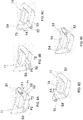
- the cam (11) comprises a perimeter frame (12) that defines a housing wherein a central island (13) with substantially trapezoidal shape is disposed.
- the central island (13) has a first side (13a), a second side (13b), a third side (13c) and a fourth side (13d).
- housings S1, S2, S3, S4 are defined in the perimeter frame (12), being disposed in the four corners of the central island (13).
- first track (T1) going from the first housing (S1) to the second housing (S2)
- second track (T2) going from the second housing (S2) to the third housing (S3)
- third track (T3) going from the third housing (S3) to the fourth housing (S4)
- fourth track (T4) going from the fourth housing (S4) to the first housing (S1).
- the four tracks (T1, T2, T3, T4) form a closed loop circuit.
- the follower (52) is obtained in the actuation lever (5) and the cam (11) is obtained in the wall (1) of the box
- the follower can be likewise obtained in the wall (1) of the box and the cam can be obtained in the body (56) of the actuation lever (5).
- a spring (M) stresses the actuation lever (5) upwards, in parallel direction to the arrow (Y), creating a moment that tends to return the actuation lever (5) to the starting position.
- the spring (M) is a torsional spring provided with an end that pushes a pin (53) disposed in the body (56) of the actuation lever (5).
- the actuation lever (5) comprises a second arm (54) that protrudes from the body (56) of the actuation lever in a direction that is parallel to the axis X and orthogonal to the first arm (51).
- the actuation lever (5) is moved by an electrical motor (9) by means of a transmission (A).
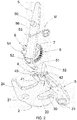
- the transmission (A) comprises an endless screw (8) actuated by the electrical motor (9) that drives into rotation a toothed wheel (7) that moves the actuation lever (5).
- the toothed wheel (7) is revolvingly mounted in the box in such a way to rotate around an axis that is parallel to the axis Z.
- the toothed wheel (7) has teeth (70), preferably of helical type.
- the endless screw (8) engages in the teeth (70) of the toothed wheel in order to rotate the toothed wheel (7).
- the endless screw (8) is supported by a drive shaft (90) of the electrical motor (9).
- the electrical motor (9) rotates only in one direction.
- the toothed wheel (7) comprises at least one protruding wing (6) suitable for pushing the actuation lever.
- three protruding wings (6) are provided in peripheral position in the toothed wheel (7), protruding from the toothed wheel in parallel direction to the axis Z in order to be stopped against the second arm (54) of the actuation lever.
- the toothed wheel comprises three protruding wings (6) that are angularly spaced by an angle of approximately 120°.
- the electrical motor (9) is configured in such a way to actuate the toothed wheel (30) in steps. Every time the electrical motor (9) is actuated, the toothed wheel (7) rotates by an angle that is a submultiple of the round angle, for example such an angle is one third of a round angle, i.e. 120°. Consequently, one of the protruding wings (6) of the toothed wheel is stopped against the second arm (54) of the actuation lever, permitting a movement of the actuation lever, in accordance with the pin (50) of the actuation lever engaged in the slot (10) of the wall and with the follower (52) of the actuation lever that circulates in the cam (11) of the wall of the box.
- the lock (100) is in closed position.
- the closing hook (2) locks the pin (not shown) of the chassis of the vehicle;
- the pawl (3) locks the closing hook (2);
- the arms (41, 42) of the memory lever (4) are respectively stopped against the second tooth (23) of the closing hook and against the projection (32) of the pawl;
- the first arm (51) of the actuation lever (5) is in distal position with respect to the projection (32) of the pawl (3).
- the endless screw (8) engages with the teeth (70) of the toothed wheel, rotating the toothed wheel (7) by 120°. Consequently, one of the protruding wings (6) of the toothed wheel is stopped against the second arm (54) of the actuation lever, pushing the second arm (54) of the actuation lever and moving the actuation lever (5).
- the pin (50) of the actuation lever can rotate and translate in the island (10)
- the follower (52) of the actuation lever moves in the direction of the arrow F1 along the first track (T1) of the cam, passes beyond the second housing (S2) and moves in the direction of the arrow F2 along the second track (T2) of the cam.
- the follower (52) moves along the first track (T1) of the cam, the actuation lever (5) is lowered and the spring (M) is loaded.
- the first arm (51) of the actuation lever (5) is stopped against the projection (32) of the pawl (3).
- the follower (52) of the actuation lever is disposed in the middle of the second track (T2).
- the first arm (51) of the actuation lever pushes the projection (32) of the pawl.
- the follower (52) moves along the second track (T2) in the direction of the arrow F3.
- the pawl (3) rotates around its pivoting axis and the tooth (30) of the pawl disengages the first tooth (22) of the closing hook.
- the closing hook (2) is free and can be opened, by opening the lid, in such a way that the pin is disengaged from the housing of the closing hook.
- the second arm (42) of the memory lever is disengaged from the projection (32) of the pawl.
- the follower (52) of the actuation lever is in the third housing (S3) of the cam.
- the spring (M) pushes the actuation lever (5) upwards; therefore, the follower (52) of the actuation lever moves in the direction of the arrow F4 along the third track (T3) of the cam.
- the actuation lever (5) is lifted, starting the resetting step of the actuation lever, as shown in Figs. 6 and 6A .
- the follower (52) reaches the fourth housing (S4) of the cam.
- the toothed wheel (7) does not rotate during the resetting step of the actuation lever (5); therefore there is no engagement between the endless screw (8) and the teeth of the toothed wheel (7), thus eliminating any kind of gear noise.
- the only gear noise is generated during the opening step, when the toothed wheel (7) engages with the endless screw (8) in order to be rotated by 120°.
Landscapes
- Lock And Its Accessories (AREA)
Claims (11)
- Schloss (100) für Fahrzeugtür und/oder -klappe umfassend:- einen Schließhaken (2), der an einem Gehäuse des Schlosses um eine Schwenkachse gelenkig gelagert ist, wobei der Schließhaken (2) einen Schlitz (20) umfasst, der geeignet ist, an einem Stift anzukuppeln, der an der Karosserie des Fahrzeug befestigt ist,- eine Sperrklinke (3), die an dem Gehäuse des Schlosses um eine Schwenkachse gelenkig gelagert ist und auf den Schließhaken (2) wirkt, um den Schließhaken in der Schließstellung zu sperren,- einen Betätigungshebel (5), der auf die Sperrklinke (3) wirkt, um die Sperrklinke aus einer Schließstellung freizugeben,- einen Elektromotor (9), der mittels Übertragungsmitteln (A) den Betätigungshebel (5) betätigt,wobei der Betätigungshebel (5) einen Körper (56) aufweist, der mit einer Wand (1) des Gehäuses verbunden ist, um in Bezug auf die Wand (1) des Gehäuses drehbar und verschieblich zu sein,
dadurch gekennzeichnet, dass
der Betätigungshebel (5) die Wand (1) des Gehäuses im Mitnehmer-(52) und Nocken- (11) Kupplungsmodus in Eingriff nimmt, wobei die Nocke (11) einen geschlossenen Kreislauf definiert, um die Bewegung des Betätigungshebels (5) zu steuern. - Schloss (100) nach Anspruch 1, wobei die Sperrklinke (3) die Form eines L-förmigen Hebels aufweist,
umfassend eine Auskragung (32) und wobei der Betätigungshebel (5) L-förmig ist und einen an der Wand angelenkten Körper (56) sowie einen ersten Arm (51) umfasst, der aus dem Körper auskragt, um gegen die Auskragung (32) der Sperrklinke in Anschlag zu gehen, wobei die Schwenkachse der Sperrklinke rechtwinklig zur Schwenkachse des Betätigungshebels verläuft. - Schloss (100) nach Anspruch 1 oder 2, wobei die Übertragungsmittel (A) eine Endlosschraube (8) umfassen, die vom Elektromotor (9) betätigt wird und in die Zähne (70) eines Zahnrades (7) eingreift, das dazu geeignet ist, den Betätigungshebel (5) zu bewegen.
- Schloss (100) nach Anspruch 3, wobei das Zahnrad (7) wenigstens einen auskragenden Flügel (6) umfasst, der aus dem Zahnrad auskragt, um gegen einen zweiten Arm (54) des Betätigungshebels in Anschlag zu gehen, der aus dem Körper (56) des Betätigungshebels auskragt.
- Schloss (100) nach Anspruch 4, wobei das Zahnrad (7) drei auskragende Flügel (6) umfasst, die gleichmäßig voneinander beabstandet in einem Winkel von 120° angeordnet sind.
- Schloss (100) nach einem der vorstehenden Ansprüche, wobei die Nocke (11) einen umlaufenden Rahmen (12) umfasst, der ein Gehäuse definiert, in dem eine zentrale, im Wesentlichen trapezförmige Insel (13) mit vier Seiten (13a, 13b, 13c, 13d) angeordnet ist, die vier Spuren (T1, T2, T3, T4) definieren.
- Schloss (100) nach einem der vorstehenden Ansprüche, umfassend eine Feder (M), die den Betätigungshebel spannt.
- Schloss (100) nach einem der vorstehenden Ansprüche, wobei der Elektromotor (9) ausgebildet ist, um das Zahnrad (7) um einem Winkel in Rotation zu versetzen, welcher ein Bruchteil eines Vollwinkels bei jeder Betätigung des Elektromotors ist.
- Schloss (100) nach Anspruch 8, wobei der Elektromotor (9) ausgebildet ist, um das Zahnrad (7) bei jeder Betätigung des Elektromotors in eine Rotation von 120° zu versetzen.
- Schloss (100) nach einem der vorstehenden Ansprüche, wobei der Betätigungshebel (5) einen Stift (50) aufweist, der aus dem Körper (56) des Betätigungshebels auskragt und einen Schlitz (10) in Eingriff nimmt, der aus der Wand des Gehäuses herausgearbeitet ist, derart, dass der Stift (50) des Betätigungshebels drehbar und in dem Schlitz (10) der Wand des Gehäuse verschieblich ist.
- Schloss (100) nach einem der vorstehenden Ansprüche, wobei der Mitnehmer (52) ein Stift ist, der aus dem Körper (56) des Betätigungshebels auskragt und die Nocke (11) aus der Wand (1) des Gehäuses herausgearbeitet ist.
Applications Claiming Priority (1)
| Application Number | Priority Date | Filing Date | Title |
|---|---|---|---|
| IT102016000108219A IT201600108219A1 (it) | 2016-10-26 | 2016-10-26 | Serratura silenziosa per portello di veicolo con leva di azionamento. |
Publications (2)
| Publication Number | Publication Date |
|---|---|
| EP3315697A1 EP3315697A1 (de) | 2018-05-02 |
| EP3315697B1 true EP3315697B1 (de) | 2018-12-12 |
Family
ID=58054452
Family Applications (1)
| Application Number | Title | Priority Date | Filing Date |
|---|---|---|---|
| EP17196555.1A Not-in-force EP3315697B1 (de) | 2016-10-26 | 2017-10-16 | Geräuschloses schloss für eine kraftfahrzeugtür und/oder einen deckel mit betätigungshebel |
Country Status (5)
| Country | Link |
|---|---|
| US (1) | US20180112443A1 (de) |
| EP (1) | EP3315697B1 (de) |
| CN (1) | CN108060843A (de) |
| BR (1) | BR102017022750A2 (de) |
| IT (1) | IT201600108219A1 (de) |
Families Citing this family (8)
| Publication number | Priority date | Publication date | Assignee | Title |
|---|---|---|---|---|
| JP6583689B2 (ja) * | 2016-06-20 | 2019-10-02 | 三井金属アクト株式会社 | 車両トランクリッド用ラッチ装置 |
| EP3511496B1 (de) * | 2018-01-10 | 2020-07-08 | U-Shin France | Schloss für kraftfahrzeug mit drei positionen |
| JP6896975B2 (ja) * | 2019-01-11 | 2021-06-30 | 三井金属アクト株式会社 | ドアロック装置 |
| CN112177449B (zh) * | 2020-10-29 | 2024-05-10 | 无锡忻润汽车安全系统有限公司 | 用于汽车的一体式行李箱锁 |
| CN112878821B (zh) * | 2021-02-26 | 2021-12-10 | 恩坦华汽车零部件(镇江)有限公司 | 一种带超越控制机构的电吸合汽车门锁 |
| US12503883B2 (en) * | 2022-07-27 | 2025-12-23 | Ts Tech Co., Ltd. | Locking device and vehicle seat with locking device |
| DE102022124185A1 (de) * | 2022-09-21 | 2024-03-21 | Kiekert Aktiengesellschaft | Kraftfahrzeug-Schloss insbesondere Kraftfahrzeug-Türschloss |
| DE102022124186A1 (de) * | 2022-09-21 | 2024-03-21 | Kiekert Aktiengesellschaft | Kfz-Schloss |
Family Cites Families (7)
| Publication number | Priority date | Publication date | Assignee | Title |
|---|---|---|---|---|
| US4351288A (en) * | 1981-06-17 | 1982-09-28 | White Consolidated Industries, Inc. | Oven door latch |
| DE3150621C2 (de) * | 1981-12-21 | 1986-12-18 | Kiekert GmbH & Co KG, 5628 Heiligenhaus | Türverschluß für eine Kraftfahrzeugtür |
| EP1245764B1 (de) * | 2001-03-28 | 2007-05-30 | Aisin Seiki Kabushiki Kaisha | Betätigungsvorrichtung eines Fahrzeugtürschlosses |
| GB0214817D0 (en) * | 2002-06-27 | 2002-08-07 | Arvinmeritor Light Vehicle Sys | Door latch mechanism |
| JP4473918B2 (ja) * | 2008-03-28 | 2010-06-02 | 三井金属鉱業株式会社 | 自動車用ドアラッチ装置 |
| CN103291131B (zh) * | 2011-12-23 | 2016-01-27 | 因特瓦产品有限责任公司 | 动力闭锁-解锁装置 |
| JP6126909B2 (ja) * | 2013-05-21 | 2017-05-10 | 株式会社ユーシン | ドアロック装置 |
-
2016
- 2016-10-26 IT IT102016000108219A patent/IT201600108219A1/it unknown
-
2017
- 2017-10-16 EP EP17196555.1A patent/EP3315697B1/de not_active Not-in-force
- 2017-10-16 US US15/784,531 patent/US20180112443A1/en not_active Abandoned
- 2017-10-23 BR BR102017022750-2A patent/BR102017022750A2/pt not_active Application Discontinuation
- 2017-10-25 CN CN201711008138.6A patent/CN108060843A/zh active Pending
Non-Patent Citations (1)
| Title |
|---|
| None * |
Also Published As
| Publication number | Publication date |
|---|---|
| CN108060843A (zh) | 2018-05-22 |
| IT201600108219A1 (it) | 2018-04-26 |
| BR102017022750A2 (pt) | 2018-05-29 |
| US20180112443A1 (en) | 2018-04-26 |
| EP3315697A1 (de) | 2018-05-02 |
Similar Documents
| Publication | Publication Date | Title |
|---|---|---|
| EP3315697B1 (de) | Geräuschloses schloss für eine kraftfahrzeugtür und/oder einen deckel mit betätigungshebel | |
| US9617761B2 (en) | Motor vehicle door lock | |
| US11859416B2 (en) | Latch assembly with power release and dual stage cinch function | |
| US5769468A (en) | Power-assist motor-vehicle door latch | |
| US10358848B2 (en) | Motor vehicle door lock | |
| US6764113B1 (en) | Powered vehicle door latch and actuator therefor | |
| EP3284887B1 (de) | Schloss für kraftfahrzeugtür oder -klappe | |
| CN114016826A (zh) | 智能闩锁 | |
| US9670701B2 (en) | Motor-vehicle door latch device | |
| GB2458567A (en) | Door latch in a motor vehicle | |
| KR101918367B1 (ko) | 차량용 트렁크 래치 모듈 | |
| PT2013079321Y (pt) | Servomecanismo usado para abrir um fecho | |
| CN110145189B (zh) | 电吸锁 | |
| EP1212501B1 (de) | Kraftangetriebene fahrzeugstürverriegelung und betätigungsvorrichtung dafür | |
| US11619075B2 (en) | Motor vehicle door lock | |
| JP6051484B2 (ja) | ドアロック装置 | |
| JP7764493B2 (ja) | 自動車用途の為の電動駆動装置 | |
| WO2003071064A1 (en) | Latch having releasable cinching mechanism | |
| JP4244146B2 (ja) | バックドアロック装置 | |
| WO2019110188A1 (en) | Lock for a motor vehicle door and/or lid with return springs | |
| CN223689484U (zh) | 一种自吸一体锁 | |
| JP4961621B2 (ja) | 不正解錠防止機構 | |
| WO2018185209A1 (en) | Lock for motor vehicle door or lid | |
| WO2001063075A1 (en) | Power striker mechanism with backdrive prevention | |
| CN220059230U (zh) | 一种门锁机构及烹饪设备 |
Legal Events
| Date | Code | Title | Description |
|---|---|---|---|
| PUAI | Public reference made under article 153(3) epc to a published international application that has entered the european phase |
Free format text: ORIGINAL CODE: 0009012 |
|
| STAA | Information on the status of an ep patent application or granted ep patent |
Free format text: STATUS: THE APPLICATION HAS BEEN PUBLISHED |
|
| AK | Designated contracting states |
Kind code of ref document: A1 Designated state(s): AL AT BE BG CH CY CZ DE DK EE ES FI FR GB GR HR HU IE IS IT LI LT LU LV MC MK MT NL NO PL PT RO RS SE SI SK SM TR |
|
| AX | Request for extension of the european patent |
Extension state: BA ME |
|
| STAA | Information on the status of an ep patent application or granted ep patent |
Free format text: STATUS: REQUEST FOR EXAMINATION WAS MADE |
|
| GRAP | Despatch of communication of intention to grant a patent |
Free format text: ORIGINAL CODE: EPIDOSNIGR1 |
|
| STAA | Information on the status of an ep patent application or granted ep patent |
Free format text: STATUS: GRANT OF PATENT IS INTENDED |
|
| 17P | Request for examination filed |
Effective date: 20180518 |
|
| RBV | Designated contracting states (corrected) |
Designated state(s): AL AT BE BG CH CY CZ DE DK EE ES FI FR GB GR HR HU IE IS IT LI LT LU LV MC MK MT NL NO PL PT RO RS SE SI SK SM TR |
|
| INTG | Intention to grant announced |
Effective date: 20180625 |
|
| GRAS | Grant fee paid |
Free format text: ORIGINAL CODE: EPIDOSNIGR3 |
|
| GRAA | (expected) grant |
Free format text: ORIGINAL CODE: 0009210 |
|
| STAA | Information on the status of an ep patent application or granted ep patent |
Free format text: STATUS: THE PATENT HAS BEEN GRANTED |
|
| AK | Designated contracting states |
Kind code of ref document: B1 Designated state(s): AL AT BE BG CH CY CZ DE DK EE ES FI FR GB GR HR HU IE IS IT LI LT LU LV MC MK MT NL NO PL PT RO RS SE SI SK SM TR |
|
| REG | Reference to a national code |
Ref country code: GB Ref legal event code: FG4D |
|
| REG | Reference to a national code |
Ref country code: CH Ref legal event code: EP |
|
| REG | Reference to a national code |
Ref country code: AT Ref legal event code: REF Ref document number: 1076189 Country of ref document: AT Kind code of ref document: T Effective date: 20181215 |
|
| REG | Reference to a national code |
Ref country code: DE Ref legal event code: R096 Ref document number: 602017001369 Country of ref document: DE |
|
| REG | Reference to a national code |
Ref country code: IE Ref legal event code: FG4D |
|
| REG | Reference to a national code |
Ref country code: NL Ref legal event code: MP Effective date: 20181212 |
|
| REG | Reference to a national code |
Ref country code: LT Ref legal event code: MG4D |
|
| PG25 | Lapsed in a contracting state [announced via postgrant information from national office to epo] |
Ref country code: FI Free format text: LAPSE BECAUSE OF FAILURE TO SUBMIT A TRANSLATION OF THE DESCRIPTION OR TO PAY THE FEE WITHIN THE PRESCRIBED TIME-LIMIT Effective date: 20181212 Ref country code: HR Free format text: LAPSE BECAUSE OF FAILURE TO SUBMIT A TRANSLATION OF THE DESCRIPTION OR TO PAY THE FEE WITHIN THE PRESCRIBED TIME-LIMIT Effective date: 20181212 Ref country code: LV Free format text: LAPSE BECAUSE OF FAILURE TO SUBMIT A TRANSLATION OF THE DESCRIPTION OR TO PAY THE FEE WITHIN THE PRESCRIBED TIME-LIMIT Effective date: 20181212 Ref country code: NO Free format text: LAPSE BECAUSE OF FAILURE TO SUBMIT A TRANSLATION OF THE DESCRIPTION OR TO PAY THE FEE WITHIN THE PRESCRIBED TIME-LIMIT Effective date: 20190312 Ref country code: ES Free format text: LAPSE BECAUSE OF FAILURE TO SUBMIT A TRANSLATION OF THE DESCRIPTION OR TO PAY THE FEE WITHIN THE PRESCRIBED TIME-LIMIT Effective date: 20181212 Ref country code: BG Free format text: LAPSE BECAUSE OF FAILURE TO SUBMIT A TRANSLATION OF THE DESCRIPTION OR TO PAY THE FEE WITHIN THE PRESCRIBED TIME-LIMIT Effective date: 20190312 Ref country code: LT Free format text: LAPSE BECAUSE OF FAILURE TO SUBMIT A TRANSLATION OF THE DESCRIPTION OR TO PAY THE FEE WITHIN THE PRESCRIBED TIME-LIMIT Effective date: 20181212 |
|
| REG | Reference to a national code |
Ref country code: AT Ref legal event code: MK05 Ref document number: 1076189 Country of ref document: AT Kind code of ref document: T Effective date: 20181212 |
|
| PG25 | Lapsed in a contracting state [announced via postgrant information from national office to epo] |
Ref country code: AL Free format text: LAPSE BECAUSE OF FAILURE TO SUBMIT A TRANSLATION OF THE DESCRIPTION OR TO PAY THE FEE WITHIN THE PRESCRIBED TIME-LIMIT Effective date: 20181212 Ref country code: SE Free format text: LAPSE BECAUSE OF FAILURE TO SUBMIT A TRANSLATION OF THE DESCRIPTION OR TO PAY THE FEE WITHIN THE PRESCRIBED TIME-LIMIT Effective date: 20181212 Ref country code: GR Free format text: LAPSE BECAUSE OF FAILURE TO SUBMIT A TRANSLATION OF THE DESCRIPTION OR TO PAY THE FEE WITHIN THE PRESCRIBED TIME-LIMIT Effective date: 20190313 Ref country code: RS Free format text: LAPSE BECAUSE OF FAILURE TO SUBMIT A TRANSLATION OF THE DESCRIPTION OR TO PAY THE FEE WITHIN THE PRESCRIBED TIME-LIMIT Effective date: 20181212 |
|
| PG25 | Lapsed in a contracting state [announced via postgrant information from national office to epo] |
Ref country code: NL Free format text: LAPSE BECAUSE OF FAILURE TO SUBMIT A TRANSLATION OF THE DESCRIPTION OR TO PAY THE FEE WITHIN THE PRESCRIBED TIME-LIMIT Effective date: 20181212 |
|
| PG25 | Lapsed in a contracting state [announced via postgrant information from national office to epo] |
Ref country code: PL Free format text: LAPSE BECAUSE OF FAILURE TO SUBMIT A TRANSLATION OF THE DESCRIPTION OR TO PAY THE FEE WITHIN THE PRESCRIBED TIME-LIMIT Effective date: 20181212 Ref country code: PT Free format text: LAPSE BECAUSE OF FAILURE TO SUBMIT A TRANSLATION OF THE DESCRIPTION OR TO PAY THE FEE WITHIN THE PRESCRIBED TIME-LIMIT Effective date: 20190412 Ref country code: CZ Free format text: LAPSE BECAUSE OF FAILURE TO SUBMIT A TRANSLATION OF THE DESCRIPTION OR TO PAY THE FEE WITHIN THE PRESCRIBED TIME-LIMIT Effective date: 20181212 Ref country code: IT Free format text: LAPSE BECAUSE OF FAILURE TO SUBMIT A TRANSLATION OF THE DESCRIPTION OR TO PAY THE FEE WITHIN THE PRESCRIBED TIME-LIMIT Effective date: 20181212 |
|
| PG25 | Lapsed in a contracting state [announced via postgrant information from national office to epo] |
Ref country code: SM Free format text: LAPSE BECAUSE OF FAILURE TO SUBMIT A TRANSLATION OF THE DESCRIPTION OR TO PAY THE FEE WITHIN THE PRESCRIBED TIME-LIMIT Effective date: 20181212 Ref country code: EE Free format text: LAPSE BECAUSE OF FAILURE TO SUBMIT A TRANSLATION OF THE DESCRIPTION OR TO PAY THE FEE WITHIN THE PRESCRIBED TIME-LIMIT Effective date: 20181212 Ref country code: IS Free format text: LAPSE BECAUSE OF FAILURE TO SUBMIT A TRANSLATION OF THE DESCRIPTION OR TO PAY THE FEE WITHIN THE PRESCRIBED TIME-LIMIT Effective date: 20190412 Ref country code: SK Free format text: LAPSE BECAUSE OF FAILURE TO SUBMIT A TRANSLATION OF THE DESCRIPTION OR TO PAY THE FEE WITHIN THE PRESCRIBED TIME-LIMIT Effective date: 20181212 Ref country code: RO Free format text: LAPSE BECAUSE OF FAILURE TO SUBMIT A TRANSLATION OF THE DESCRIPTION OR TO PAY THE FEE WITHIN THE PRESCRIBED TIME-LIMIT Effective date: 20181212 |
|
| REG | Reference to a national code |
Ref country code: DE Ref legal event code: R097 Ref document number: 602017001369 Country of ref document: DE |
|
| PLBE | No opposition filed within time limit |
Free format text: ORIGINAL CODE: 0009261 |
|
| STAA | Information on the status of an ep patent application or granted ep patent |
Free format text: STATUS: NO OPPOSITION FILED WITHIN TIME LIMIT |
|
| PG25 | Lapsed in a contracting state [announced via postgrant information from national office to epo] |
Ref country code: DK Free format text: LAPSE BECAUSE OF FAILURE TO SUBMIT A TRANSLATION OF THE DESCRIPTION OR TO PAY THE FEE WITHIN THE PRESCRIBED TIME-LIMIT Effective date: 20181212 Ref country code: AT Free format text: LAPSE BECAUSE OF FAILURE TO SUBMIT A TRANSLATION OF THE DESCRIPTION OR TO PAY THE FEE WITHIN THE PRESCRIBED TIME-LIMIT Effective date: 20181212 |
|
| 26N | No opposition filed |
Effective date: 20190913 |
|
| PG25 | Lapsed in a contracting state [announced via postgrant information from national office to epo] |
Ref country code: TR Free format text: LAPSE BECAUSE OF FAILURE TO SUBMIT A TRANSLATION OF THE DESCRIPTION OR TO PAY THE FEE WITHIN THE PRESCRIBED TIME-LIMIT Effective date: 20181212 |
|
| REG | Reference to a national code |
Ref country code: DE Ref legal event code: R119 Ref document number: 602017001369 Country of ref document: DE |
|
| PG25 | Lapsed in a contracting state [announced via postgrant information from national office to epo] |
Ref country code: MC Free format text: LAPSE BECAUSE OF FAILURE TO SUBMIT A TRANSLATION OF THE DESCRIPTION OR TO PAY THE FEE WITHIN THE PRESCRIBED TIME-LIMIT Effective date: 20181212 |
|
| PG25 | Lapsed in a contracting state [announced via postgrant information from national office to epo] |
Ref country code: LU Free format text: LAPSE BECAUSE OF NON-PAYMENT OF DUE FEES Effective date: 20191016 Ref country code: DE Free format text: LAPSE BECAUSE OF NON-PAYMENT OF DUE FEES Effective date: 20200501 |
|
| REG | Reference to a national code |
Ref country code: BE Ref legal event code: MM Effective date: 20191031 |
|
| PG25 | Lapsed in a contracting state [announced via postgrant information from national office to epo] |
Ref country code: BE Free format text: LAPSE BECAUSE OF NON-PAYMENT OF DUE FEES Effective date: 20191031 |
|
| PG25 | Lapsed in a contracting state [announced via postgrant information from national office to epo] |
Ref country code: IE Free format text: LAPSE BECAUSE OF NON-PAYMENT OF DUE FEES Effective date: 20191016 Ref country code: FR Free format text: LAPSE BECAUSE OF NON-PAYMENT OF DUE FEES Effective date: 20191031 |
|
| PG25 | Lapsed in a contracting state [announced via postgrant information from national office to epo] |
Ref country code: CY Free format text: LAPSE BECAUSE OF FAILURE TO SUBMIT A TRANSLATION OF THE DESCRIPTION OR TO PAY THE FEE WITHIN THE PRESCRIBED TIME-LIMIT Effective date: 20181212 |
|
| REG | Reference to a national code |
Ref country code: CH Ref legal event code: PL |
|
| PG25 | Lapsed in a contracting state [announced via postgrant information from national office to epo] |
Ref country code: LI Free format text: LAPSE BECAUSE OF FAILURE TO SUBMIT A TRANSLATION OF THE DESCRIPTION OR TO PAY THE FEE WITHIN THE PRESCRIBED TIME-LIMIT Effective date: 20201031 Ref country code: CH Free format text: LAPSE BECAUSE OF FAILURE TO SUBMIT A TRANSLATION OF THE DESCRIPTION OR TO PAY THE FEE WITHIN THE PRESCRIBED TIME-LIMIT Effective date: 20201031 |
|
| PG25 | Lapsed in a contracting state [announced via postgrant information from national office to epo] |
Ref country code: MT Free format text: LAPSE BECAUSE OF FAILURE TO SUBMIT A TRANSLATION OF THE DESCRIPTION OR TO PAY THE FEE WITHIN THE PRESCRIBED TIME-LIMIT Effective date: 20181212 Ref country code: HU Free format text: LAPSE BECAUSE OF FAILURE TO SUBMIT A TRANSLATION OF THE DESCRIPTION OR TO PAY THE FEE WITHIN THE PRESCRIBED TIME-LIMIT; INVALID AB INITIO Effective date: 20171016 |
|
| PG25 | Lapsed in a contracting state [announced via postgrant information from national office to epo] |
Ref country code: SI Free format text: LAPSE BECAUSE OF FAILURE TO SUBMIT A TRANSLATION OF THE DESCRIPTION OR TO PAY THE FEE WITHIN THE PRESCRIBED TIME-LIMIT Effective date: 20181212 |
|
| GBPC | Gb: european patent ceased through non-payment of renewal fee |
Effective date: 20211016 |
|
| PG25 | Lapsed in a contracting state [announced via postgrant information from national office to epo] |
Ref country code: MK Free format text: LAPSE BECAUSE OF FAILURE TO SUBMIT A TRANSLATION OF THE DESCRIPTION OR TO PAY THE FEE WITHIN THE PRESCRIBED TIME-LIMIT Effective date: 20181212 |
|
| PG25 | Lapsed in a contracting state [announced via postgrant information from national office to epo] |
Ref country code: GB Free format text: LAPSE BECAUSE OF NON-PAYMENT OF DUE FEES Effective date: 20211016 |