EP3315266B1 - Gewichtsausgleicher - Google Patents
Gewichtsausgleicher Download PDFInfo
- Publication number
- EP3315266B1 EP3315266B1 EP17193802.0A EP17193802A EP3315266B1 EP 3315266 B1 EP3315266 B1 EP 3315266B1 EP 17193802 A EP17193802 A EP 17193802A EP 3315266 B1 EP3315266 B1 EP 3315266B1
- Authority
- EP
- European Patent Office
- Prior art keywords
- spring
- spindle
- balancer
- balancer according
- compression spring
- Prior art date
- Legal status (The legal status is an assumption and is not a legal conclusion. Google has not performed a legal analysis and makes no representation as to the accuracy of the status listed.)
- Active
Links
Images

Classifications
-
- B—PERFORMING OPERATIONS; TRANSPORTING
- B24—GRINDING; POLISHING
- B24B—MACHINES, DEVICES, OR PROCESSES FOR GRINDING OR POLISHING; DRESSING OR CONDITIONING OF ABRADING SURFACES; FEEDING OF GRINDING, POLISHING, OR LAPPING AGENTS
- B24B41/00—Component parts such as frames, beds, carriages, headstocks
- B24B41/04—Headstocks; Working-spindles; Features relating thereto
- B24B41/042—Balancing mechanisms
-
- B—PERFORMING OPERATIONS; TRANSPORTING
- B25—HAND TOOLS; PORTABLE POWER-DRIVEN TOOLS; MANIPULATORS
- B25H—WORKSHOP EQUIPMENT, e.g. FOR MARKING-OUT WORK; STORAGE MEANS FOR WORKSHOPS
- B25H1/00—Work benches; Portable stands or supports for positioning portable tools or work to be operated on thereby
- B25H1/0021—Stands, supports or guiding devices for positioning portable tools or for securing them to the work
- B25H1/0028—Tool balancers
-
- B—PERFORMING OPERATIONS; TRANSPORTING
- B25—HAND TOOLS; PORTABLE POWER-DRIVEN TOOLS; MANIPULATORS
- B25J—MANIPULATORS; CHAMBERS PROVIDED WITH MANIPULATION DEVICES
- B25J19/00—Accessories fitted to manipulators, e.g. for monitoring, for viewing; Safety devices combined with or specially adapted for use in connection with manipulators
- B25J19/0008—Balancing devices
- B25J19/0016—Balancing devices using springs
-
- B—PERFORMING OPERATIONS; TRANSPORTING
- B66—HOISTING; LIFTING; HAULING
- B66D—CAPSTANS; WINCHES; TACKLES, e.g. PULLEY BLOCKS; HOISTS
- B66D1/00—Rope, cable, or chain winding mechanisms; Capstans
- B66D1/02—Driving gear
- B66D1/08—Driving gear incorporating fluid motors
-
- F—MECHANICAL ENGINEERING; LIGHTING; HEATING; WEAPONS; BLASTING
- F16—ENGINEERING ELEMENTS AND UNITS; GENERAL MEASURES FOR PRODUCING AND MAINTAINING EFFECTIVE FUNCTIONING OF MACHINES OR INSTALLATIONS; THERMAL INSULATION IN GENERAL
- F16F—SPRINGS; SHOCK-ABSORBERS; MEANS FOR DAMPING VIBRATION
- F16F1/00—Springs
- F16F1/02—Springs made of steel or other material having low internal friction; Wound, torsion, leaf, cup, ring or the like springs, the material of the spring not being relevant
- F16F1/04—Wound springs
- F16F1/12—Attachments or mountings
- F16F1/128—Attachments or mountings with motion-limiting means, e.g. with a full-length guide element or ball joint connections; with protective outer cover
-
- G—PHYSICS
- G01—MEASURING; TESTING
- G01G—WEIGHING
- G01G3/00—Weighing apparatus characterised by the use of elastically-deformable members, e.g. spring balances
- G01G3/06—Weighing apparatus characterised by the use of elastically-deformable members, e.g. spring balances wherein the weighing element is in the form of a spiral spring
-
- G—PHYSICS
- G05—CONTROLLING; REGULATING
- G05G—CONTROL DEVICES OR SYSTEMS INSOFAR AS CHARACTERISED BY MECHANICAL FEATURES ONLY
- G05G2700/00—Control mechanisms or elements therefor applying a mechanical movement
- G05G2700/12—Control mechanisms with one controlling member and one controlled member
- G05G2700/14—Control mechanisms with one controlling member and one controlled member with one elastic element as essential part, e.g. elastic components as a part of an actuating mechanism
Definitions
- the invention relates to a weight compensator, in particular a spring tension or a balancer, for a movable component with a component weight to be compensated.
- Weight balancers such as balancers or balancers are used to balance the dead weight of a component to be handled in the sense that the person using the component does not have to bear its weight. This is relevant, for example, in production plants in which heavy tools have to be used for a specific production step. So that the pavers do not have to bear their weight permanently while using the corresponding tool, but can concentrate on the fine motor application of the tool, the weight compensators mentioned are used.
- the weight compensator can be hung for example on a crossbeam in the roof construction, and the component to be compensated in turn be hung on the counterbalance.
- Known weight balancers have a spiral spring, which is deflected so long after hanging the component until the bending deflection of the coil spring pulls so strong a spring force that the weight of the suspended component is compensated.
- the component is fastened with a snap hook to a cable, which in turn is fastened at its other end to the outer end of the spiral spring.
- the inner end of the coil spring is non-rotatably mounted on a carrier of the known weight equalizer, wherein the carrier in turn can be attached by means of a cable and / or a snap hook on a roof beam.
- the object of the invention is to provide a mechanical weight compensator which can be used in a larger weight range and is preferably easier to adjust.
- a weight compensator in particular a spring balancer or a balancer, is provided for a movable component having a component weight, comprising a spindle gearbox with a translational element and a rotation element to which the component can be suspended, and at least one compression spring attached to one of its ends, at least indirectly - is connected to the translation element of the spindle gear.
- the compression spring is compressible at a caused by the component weight rotation of the rotary member by means of the translation element.
- the invention is based inter alia on the idea that compression springs, which are loaded along their longitudinal axis to pressure, have a proportional to the displacement along the longitudinal axis increase in the spring force, that is, a linear spring force curve.
- This distinguishes compression springs from the previously used in weight equalizers coil springs, which are not pressure-loaded in the deflection, but are flexurally flexed about its longitudinal axis. Therefore, coil springs have no linear force curve, but which is advantageous for the design of the counterbalance, in particular for its adaptation to a specific weight of the component to be compensated.
- compression springs for use in weight equalizers can be designed so that even very large weight forces and / or a large weight range can be cushioned with them. This is also difficult with coil springs, because these are at their central At the deflection, swivel the axis quickly so that, after a certain deflection, the individual layers lie against each other and no further deflection is possible.
- the invention is also based on the recognition that the use of compression springs in weight equalizers due to their typical applications requires a gearbox: weight balancers are typically suspended above the desired working space and compensate for a weight force, which necessarily acts downward. Therefore, when using compression springs for applying a force counteracting the weight force, a tensile force must be converted into a compressive force. For the purposes of the invention, this is done by means of the spindle gear, which can implement rotational movements (on the rotary member) in longitudinal movements (on the translation element). Between the rotation element and the translation element is preferably a thread, in particular with a predetermined thread pitch, arranged, which mediates this implementation.
- a compression spring according to the invention is a cylindrical coil spring which can deflect along its longitudinal axis under pressure load.
- weight compensator is used here as a collective term among other things for spring balancers and balancers, and is based on the function of these devices: a compensation of the weight of the component to be compensated.
- spring balancers also called retrievers
- weight balancers are often referred to for rather lower loads, in which also often the function of pulling and pulling back of the suspended load is important.
- balancer weight balancers are often referred to for rather higher loads, where functionally often the weight compensation stands in the foreground. Therefore, balancers are also called - in a narrower sense than used here - weight balancers.
- the spindle has a movement thread, in particular a ball or a roller thread on.
- movement threads can be designed, for example, without play and, in particular, have a lower tendency to self-locking.
- motion threads have a lower friction between the bearing partners than classical threads and are therefore well suited for the present application.
- the spindle is designed as a rotating element and the spindle nut as a translation element, or vice versa, is irrelevant to the operating principle of the invention in itself. Nevertheless, these two alternatives are provided in different embodiments of the invention, because depending on the other embodiment of the counterbalance one or the other example, have advantages in terms of power flow, a simple production and / or an optionally provided adjustment for adjusting a bias of the compression springs can.
- the compression spring and the translation element are connected by means of a contact element, which rests against the one end of the compression spring and fixed to the Translational element is connected.
- the contact element may be formed, for example, as a solid, welded to the translation element disc which can impress the arranged in the periphery of the translation element springs at their respective, the contact element facing the end.
- a longitudinal movement axis of the translation element extends parallel to the longitudinal axis of the compression spring.
- the weight compensator has a spring carrier on which the compression spring is non-rotatably arranged on the other of its ends, on which the rotation element is rotatably mounted and / or on which the weight compensator is suspended, in particular on a rope and / or a snap hook.
- the compression spring is arranged coaxially with the spindle gear and radially outside the circumference of the spindle, in particular - apart from the contact element - also radially outside the circumference of the spindle nut.
- the weight compensator may also have more than one, in particular 2, 3, 4, 6 or 8 compression springs, which are preferably parallel to each other and / or evenly spaced in the circumference of the spindle gear are arranged. This can, for example, allow a more uniform distribution of force in the spring carrier or a use of cheaper standard designs of compression springs by the applied pressure force is distributed to a plurality of compression springs.
- each of the compression springs preferably provided to arrange each of the compression springs around a bolt which is fixedly connected to the spring carrier.
- the translation element directly or indirectly by means of the contact element rotationally fixed, but free with respect to the compression direction, connected to at least one of the bolts to ensure effective power transmission in the compression direction.
- the rotation element is non-rotatably connected to a, in particular cylindrical or conical, cable drum, on whose circumference a, in particular spiral, cable receptacle is arranged on the attached during operation of the counterbalance a rope and is multiple times feasible.
- the weight-compensated component can be suspended, for example on a snap hook.
- the spindle gear can be connected to the component in such a way that a rotational movement is produced by the applied gravitational force.
- the rotation element in particular by means of an adjustment, temporarily decoupled from the cable drum (in particular with respect to rotation) and in the Rotatable relative to the translation element.
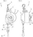
- FIG. 1 shows a trained as a spring balancer 1 in a front view.
- Fig. 2 the same counterbalance 1 is shown in a side view.
- a suspension device 4 is arranged with a snap hook 6, with which the weight compensator 1 can be hung for example on a ceiling joists or on a frame.
- the housing 3 also has a housing cover designed as a spring carrier 8, which in the embodiment (see Fig. 3 ) is screwed to the housing component 2.
- a setting device 10 is further arranged for adjusting a bias of the compression springs.
- the compression springs and the spindle gear are arranged in the interior of the housing 3 and therefore in the Figures 1 and 2 not visible.
- a cable extension 14 extends with a snap hook 16 for mounting the component with the weight to be compensated (not shown), for example, a production tool.
- the cable pullout 14 also has a cable lock 18, which limits a retraction of the cable 20 of the cable drawer 14 in the housing interior.
- the rope lock is useful in the embodiment, because the compression springs are biased (ie already compressed at rest), and thus retract the rope when no component with a certain component weight is attached thereto.
- Fig. 2 is also apparent that on the housing cover designed as a spring carrier 8, a spindle bearing 22 and fastening nuts 24 are arranged for bolts 26, which serve to prevent rotation of the compression springs 30.
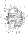
- Fig. 3 shows a sectional view along the in Fig. 1 drawn section A - A, and thus the interior of the housing. 3
- each compression spring 30 is arranged around a bolt 26, wherein the bolts are fixedly connected to the spring carrier 8.
- the housing component 2 is in turn firmly connected to the spring carrier 8.
- Each of the compression springs 30 abuts with its one end 29 on the receiving element 44, with its other end 31 on the inside of the spring carrier eighth
- a spindle gear 32 is arranged in the interior of the housing 3, which has a spindle 34 and a spindle nut 36. Between the spindle 34 and the spindle nut 36 designed as a ball screw movement thread 38 is arranged with a constant pitch (only greatly simplified shown schematically).
- the spindle 34 is rotatably mounted in the spindle bearing 22 in relation to the spring carrier 8 and thus the compression springs 30 and - at least in the operating state - rotatably connected to a cable drum 40.
- the cable drum 40 has a conical circumference and a spiral cable receptacle 42;
- other exemplary embodiments are provided with a cable drum with a cylindrical circumference.
- contact element 44 On the spindle nut 36 is rotatably and along the entire circumference designed as a circular hole plate contact element 44 is arranged, that for each bolt 26 has a through hole and against which the compression springs 30 abut with its end 29 under a pressure bias.
- the contact element 44 is welded in the exemplary embodiment with the spindle nut 36, but can also be connected to other suitable type with this.
- the cable drum 40 can be rotated together with the spindle 34 relative to the housing-rotation-resistant compression springs 30. This occurs in typical applications of the weight balancer 1, for example, when hooked into the hook 16, a production tool or other component with a relevant component weight. Then, the cable drum 40 is rotated due to the applied gravity of the component via the cable pullout 14, the rope 20 is guided in the cable holder 42 and secured thereto. The pitch direction of the movement thread 38 is selected so that when pulling out the cable pull-out 14, the spindle nut 36 - in the plane of the drawing - is moved to the left, ie equally to the spring carrier 8. The compression springs 30 are compressed by the translational movement of the threaded nut 36 is transmitted via the contact element 44 on the springs.
- the spindle 34 With a further deflection of the cable drum 40, the spindle 34 continues to rotate; the housing-rotatably arranged threaded nut 36 is thereby deflected by the action of the movement thread 38 proportionally more and more to the left.
- the force applied by the compression springs 30 on the contact element 44 pressure-spring force increases according to the spring force laws linear with the compression on. This process only comes to a halt when the weight force of the component counteracting spring force of the springs has increased so much that it holds the weight of the balance. In this state, the weight compensator can fulfill its functions mentioned above.
- an adjustment device 10 may be provided by means of the rotatable connection between the cable drum 40 and the spindle 34 can be temporarily suspended in a suitable manner, and in this bias state, the spindle 34 without twisting the cable drum 40 can be rotated, which has a displacement of the cable lock 12 predetermined rest position of the spindle nut 36 result, and thus a change in the bias of the balancer 1.
- the required rotational decoupling of the spindle 34 and the cable drum 40 for example via a Coupled and disengaged splines between the two components.
- the coupling mechanism is then part of the adjustment device 10.
- a change in the bias can also be done by changing the position of the cable lock 12 along the cable 20.
- Fig. 4 the counterbalance 1 is off Fig. 1 shown in a rear view.
- the spring carrier 8, the pin 26 and the spring bearing 22 are easily recognizable.
- the uniform distribution of the bolt 26 and thus the compression springs 30 in the circumference of the spindle 34 can be seen.
Landscapes
- Engineering & Computer Science (AREA)
- Mechanical Engineering (AREA)
- General Engineering & Computer Science (AREA)
- Physics & Mathematics (AREA)
- General Physics & Mathematics (AREA)
- Robotics (AREA)
- Manipulator (AREA)
- Transmission Devices (AREA)
Description
- Die Erfindung betrifft einen Gewichtsausgleicher, insbesondere einen Federzug oder einen Balancer, für ein bewegliches Bauteil mit einem auszugleichenden Bauteilgewicht.
- Gewichtsausgleicher wie Federzüge oder Balancer werden dazu verwendet, das Eigengewicht eines handzuhabenden Bauteils in dem Sinne auszugleichen, dass die Person, die das Bauteil verwendet, dessen Gewicht nicht tragen muss. Relevant ist dies beispielsweise in Fertigungsstätten, in denen für bestimmte Fertigungsschritt schwere Werkzeuge verwendet werden müssen. Damit die Fertiger nicht während der Verwendung des entsprechenden Werkzeuges dauerhaft dessen Gewicht tragen müssen, sondern sich auf die feinmotorische Anwendung des Werkzeugs konzentrieren können, werden die genannten Gewichtsausgleicher eingesetzt.
- Dazu kann der Gewichtsausgleicher beispielsweise an einem Querbalken in der Dachkonstruktion eingehängt werden, und das auszugleichende Bauteil seinerseits am Gewichtsausgleicher eingehängt werden.
- Bekannte Gewichtsausgleicher verfügen über eine Spiralfeder, die nach dem Einhängen des Bauteils so lange ausgelenkt wird, bis die Biegeauslenkung der Spiralfeder eine so starke Federkraft nach sich zieht, dass die Gewichtskraft des eingehängten Bauteils kompensiert wird.
- Normalerweise wird bei diesen bekannten Gewichtsausgleichern das Bauteil mit einem Karabinerhaken an einem Seil befestigt, das mit seinem anderen Ende wiederum an dem äußeren Ende der Spiralfeder befestigt ist. Das innere Ende der Spiralfeder ist drehfest an einem Träger des bekannten Gewichtsausgleichers angeordnet, wobei der Träger seinerseits mittels eines Seils und/oder eines Karabinerhakens an einem Dachbalken befestigt werden kann. Das sich so bei eingehängtem Bauteil einstellende Gleichgewicht ermöglicht einer Bedienperson, das Bauteil handzuhabenden, ohne ständig dessen Gewichtskraft als Haltekraft aufbringen zu müssen.
Die Verwendung von Spiralfedern für die Gewichtskompensation ermöglicht einen einfachen Aufbau. Allerdings sind aufgrund der Natur von Spiralfedern die maximal ausgleichbaren Traglasten - bezogen auf die Baugröße des Gewichtsausgleichers - verhältnismäßig gering. Zudem ist der Zuwachs der Federkraft bei einer bestimmten Auslenkung von der bereits erfolgten Biegung der Spiralfeder abhängig. Dies macht beispielsweise die Einstellung einer gewünschten Vorspannung zur Anpassung an ein zu erwartendes Bauteilgewicht schwierig. AusUS 3,428,298 ist beispielsweise bekannt, anstatt einer mechanischen Feder ein Gasvolumen als Feder zu verwenden, wobei der Gasdruck in dem Volumen über eine Steuereinrichtung verstellbar ist, und so den auszugleichenden Lasten angepasst werden kann. - Die Erfindung macht es sich zur Aufgabe, einen in einem größeren Gewichtsbereich einsetzbaren und vorzugsweise leichter einstellbaren mechanischen Gewichtsausgleicher bereitzustellen.
- Diese Aufgabe wird durch die im unabhängigen Anspruch angegebene Erfindung gelöst. Vorteilhafte Weiterbildungen sind den Unteransprüchen zu entnehmen.
- Erfindungsgemäß geschaffen ist ein Gewichtsausgleicher, insbesondere ein Federzug oder ein Balancer, für ein bewegliches Bauteil mit einem Bauteilgewicht, aufweisend ein Spindelgetriebe mit einem Translationselelement und einem Rotationselement, an dem das Bauteil eingehängt werden kann, und wenigstens eine Druckfeder, die an einem ihrer Enden - wenigstens mittelbar - mit dem Translationselement des Spindelgetriebes verbunden ist. Die Druckfeder ist bei einer durch das Bauteilgewicht verursachten Drehung des Rotationselements mittels des Translationselements stauchbar.
- Die Erfindung basiert unter anderem auf der Idee, dass Druckfedern, die entlang ihrer Längsachse auf Druck belastet werden, einen zur Auslenkung entlang der Längsachse proportionalen Anstieg der Federkraft aufweisen, sprich einen linearen Federkraftverlauf. Dies unterscheidet Druckfedern von den bisher in Gewichtsausgleichern verwendeten Spiralfedern, die bei der Auslenkung nicht druckbelastet, sondern um ihre Längsachse biegebelastet sind. Daher weisen Spiralfedern keinen linearen Kraftverlauf auf, der aber vorteilhaft für die Auslegung des Gewichtsausgleichers, insbesondere für dessen Anpassung an ein bestimmtes Gewicht des auszugleichenden Bauteils ist.
- Zudem können Druckfedern zur Verwendung in Gewichtsausgleichern so ausgelegt werden, dass mit ihnen auch sehr große Gewichtskräfte und/oder ein großer Gewichtskraftbereich abgefedert werden können. Auch das ist mit Spiralfedern schwierig, weil sich diese um ihre zentrale Achse bei der Auslenkung schnell zusammenziehen, sodass ab einer gewissen Auslenkung die einzelnen Lagen aneinander anliegen und keine weitere Auslenkung möglich ist.
- Die Erfindung basiert zudem auf der Erkenntnis, dass die Verwendung von Druckfedern in Gewichtsausgleichern aufgrund von deren typischen Anwendungsfällen ein Getriebe erfordert: Gewichtsausgleicher sind typischerweise über dem angestrebten Arbeitsraum aufgehängt und gleichen eine Gewichtskraft aus, die notwendigerweise nach unten wirkt. Daher muss bei der Verwendung von Druckfedern zum Aufbringen einer, der Gewichtskraft entgegenwirkenden, Federkraft eine Zugkraft in eine Druckkraft umgesetzt werden. Im Sinne der Erfindung geschieht dies mittels des Spindelgetriebes, das Rotationsbewegungen (am Rotationselement) in Längsbewegungen (am Translationselement) umsetzen kann. Zwischen dem Rotationselement und dem Translationselement ist vorzugsweise ein Gewinde, insbesondere mit einer vorbestimmten Gewindesteigung, angeordnet, das diese Umsetzung vermittelt.
- Eine Druckfeder im Sinne der Erfindung ist eine zylindrische Schraubenfeder, die entlang ihrer Längsachse bei Druckbelastung einfedern kann.
- Der Begriff Gewichtsausgleicher wird hier als Sammelbegriff unter anderem für Federzüge und Balancer verwendet, und orientiert sich an der Funktion dieser Geräte: einer Kompensation der Gewichtskraft des auszugleichenden Bauteils. Als Federzüge (auch Rückholer genannt) werden häufig Gewichtsausgleicher für eher geringere Lasten bezeichnet, bei denen zudem oft die Funktion eines Herziehens und Zurückziehens der eingehängten Last wichtig ist. Als Balancer werden häufig Gewichtsausgleicher für eher höhere Lasten bezeichnet, bei denen funktional oft die Gewichtskompensation im Vordergrund steht. Daher werden Balancer auch - in einem engeren Sinne als hier verwendet - Gewichtsausgleicher genannt.
- Weil klassische Trapezgewinde häufig zur Selbsthemmung neigen, die allenfalls durch eine extrem genaue Tolerierung und/oder eine aufwändige Schmierung reduziert werden kann, weist in einer Ausgestaltung der Erfindung die Spindel ein Bewegungsgewinde, insbesondere ein Kugel- oder ein Rollengewinde, auf. Solche Bewegungsgewinde können beispielsweise spielfrei ausgelegt werden und haben insbesondere dadurch eine geringere Neigung zur Selbsthemmung. Generell weisen Bewegungsgewinde eine niedrigere Reibung zwischen den Lagerungspartnern auf als klassische Gewinde und eignen sich deshalb für die vorliegende Anwendung gut.
- Ob bei dem verwendeten Spindelgetriebe die Spindel als Rotationselement ausgeführt ist und die Spindelmutter als Translationselement, oder andersherum, ist für das Funktionsprinzip der Erfindung an sich irrelevant. Trotzdem sind in unterschiedlichen Ausgestaltungen der Erfindung diese beiden Alternativen vorgesehen, weil in Abhängigkeit von der sonstigen Ausgestaltung des Gewichtsausgleicher die eine oder die andere Alternative beispielsweise Vorteile hinsichtlich des Kraftflusses, einer einfachen Fertigung und/oder einer gegebenenfalls vorgesehenen Einstelleinrichtung zum Einstellen einer Vorspannung der Druckfedern haben kann.
- Um eine einfache Kraftübertragung zwischen der Druckfeder und dem Spindelgetriebe zu ermöglichen, sind in einer Ausgestaltung der Erfindung die Druckfeder und das Translationselement mittels eines Anlageelements verbunden, das an dem einen Ende der Druckfeder anliegt und fest mit dem Translationselement verbunden ist. Bei einer Ausführung mit mehreren Druckfedern kann das Anlageelement beispielsweise als massive, an dem Translationselement angeschweißte Scheibe ausgebildet sein, die die im Umfang des Translationselements angeordneten Druckfedern an ihrem jeweiligen, dem Anlageelement zugewandten Ende eindrücken kann.
- Damit mittels des Spindelgetriebes in effektiver Weise eine Druckkraft auf die Druckfeder ausgeübt werden kann, verläuft nach einer Ausgestaltung der Erfindung eine Längsbewegungsachse des Translationselements parallel zu der Längsachse der Druckfeder.
- Um ein Verdrehen der Druckfeder(n) im Betrieb zu vermeiden, weist in einer Ausgestaltung der Erfindung der Gewichtsausgleicher einen Federträger auf, an welchem die Druckfeder an dem anderen ihrer Enden drehfest angeordnet ist, an welchem das Rotationselement drehbar gelagert ist und/oder an welchem der Gewichtsausgleicher aufhängbar ist, insbesondere an einem Seil und/oder einem Karabinerhaken.
- In einer Ausgestaltung der Erfindung ist die Druckfeder koaxial mit dem Spindelgetriebe und radial außerhalb des Umfangs der Spindel angeordnet, insbesondere - abgesehen von dem Anlageelement - auch radial außerhalb des Umfangs der Spindelmutter. Durch die Verwendung, beispielsweise einer einzigen, Druckfeder, die um das Spindelgetriebe herum angeordnet ist, kann ein sehr klein bauender Gewichtsausgleicher erreicht werden.
- Im Sinne der Erfindung kann der Gewichtsausgleicher auch mehr als eine, insbesondere 2, 3, 4, 6 oder 8 Druckfedern aufweisen, die vorzugsweise parallel zueinander und/oder gleichmäßig beabstandet im Umfang des Spindelgetriebes angeordnet sind. Dies kann beispielsweise eine gleichmäßiger verteilte Krafteinleitung in den Federträger oder eine Verwendung günstigerer Standardbauformen von Druckfedern ermöglichen, indem die aufzubringende Druckkraft auf mehrere Druckfedern verteilt wird.
- Als Verdrehsicherung ist, beispielsweise beim Gebrauch mehrerer Druckfedern, vorzugsweise vorgesehen, jede der Druckfedern um einen Bolzen herum anzuordnen, der fest mit dem Federträger verbunden ist.
- Dabei ist in bevorzugter Ausgestaltung das Translationselement direkt oder mittelbar mittels des Anlageelements drehfest, aber frei hinsichtlich der Stauchrichtung, mit wenigstens einem der Bolzen verbunden, um eine effektive Kraftübertragung in der Stauchrichtung sicherzustellen.
- In einer Ausgestaltung der Erfindung ist das Rotationselement drehfest mit einer, insbesondere zylindrischen oder konischen, Seiltrommel verbunden, an deren Umfang eine, insbesondere spiralförmige, Seilaufnahme angeordnet ist, an der im Betrieb des Gewichtsausgleichers ein Seil befestigt und mehrfach herumführbar ist. Vorzugsweise an dem nicht befestigten Ende des Seils ist das gewichtsmäßig auszugleichende Bauteil einhängbar, beispielsweise an einem Karabinerhaken. Dadurch kann das Spindelgetriebe derart mit dem Bauteil verbunden werden, dass durch die anliegende Schwerkraft eine Rotationsbewegung entsteht.
- In einer Ausgestaltung der Erfindung ist das Rotationselement, insbesondere mittels einer Einstelleinrichtung, vorübergehend von der Seiltrommel entkoppelbar (insbesondere bezüglich Drehung) und im Verhältnis zum Translationselement drehbar. So kann eine von der Stellung der Seilrolle unabhängige Stauchung oder Dehnung der Druckfeder erfolgen, wodurch eine einfache Voreinstellung der aufzubringenden Gegenkraft möglich wird.
- Nachfolgend sind anhand der beigefügten Zeichnungen beispielhafte Ausführungsformen der Erfindung näher beschrieben. Es zeigen:
- Fig. 1
- eine Frontalansicht eines beispielhaften Gewichtsausgleichers gemäß der Erfindung;
- Fig. 2
- eine Seitenansicht des Gewichtsausgleichers aus
Fig. 1 ; - Fig. 3
- eine Schnittansicht entlang dem in
Fig. 1 eingezeichneten Schnitt A - A; und - Fig. 4
- eine Rückansicht des Gewichtsausgleichers aus
Fig. 1 ; -
Figur 1 zeigt einen als Federzug ausgebildeten Gewichtsausgleicher 1 in einer Frontalansicht. InFig. 2 ist der gleiche Gewichtsausgleicher 1 in einer Seitenansicht dargestellt. - Aus den beiden Figuren sind die äußeren Komponenten des Gewichtsausgleichers 1 erkenntlich. An einer topfartig ausgebildeten Gehäusekomponente 2 eines Gehäuses 3 ist eine Aufhänge-Einrichtung 4 mit einem Karabinerhaken 6 angeordnet, mit welchem der Gewichtsausgleicher 1 beispielsweise an einem Deckenbalken oder an einem Rahmengestell aufgehängt werden kann.
- Das Gehäuse 3 weist zudem einen als Gehäusedeckel ausgebildeten Federträger 8 auf, der im Ausführungsbeispiel (vergleiche
Fig. 3 ) mit der Gehäusekomponente 2 verschraubt ist. An der Gehäusekomponente 2 ist ferner eine Einstellungsvorrichtung 10 zur Einstellung einer Vorspannung der Druckfedern angeordnet. - Die Druckfedern sowie das Spindelgetriebe sind im Inneren des Gehäuses 3 angeordnet und daher in den
Figuren 1 und 2 nicht sichtbar. - Aus einer nicht direkt sichtbaren Ausnehmung 12 im Gehäuse 3 erstreckt sich ein Seilauszug 14 mit einem Karabinerhaken 16 zum Einhängen des Bauteils mit dem auszugleichenden Gewicht (nicht dargestellt), beispielsweise eines Fertigungswerkzeugs.
- Der Seilauszug 14 weist zudem eine Seilsperre 18 auf, die ein Einziehen des Seils 20 des Seilauszugs 14 in das Gehäuseinnere begrenzt. Die Seilsperre ist im Ausführungsbeispiel sinnvoll, weil die Druckfedern vorgespannt sind (also bereits im Ruhezustand gestaucht), und damit das Seil einziehen, wenn kein Bauteil mit einem gewissen Bauteilgewicht daran befestigt ist.
- Aus
Fig. 2 ist zudem ersichtlich, dass an dem als Gehäusedeckel ausgebildeten Federträger 8 eine Spindellagerung 22 sowie Befestigungsmuttern 24 für Bolzen 26 angeordnet sind, die einer Verdrehsicherung der Druckfedern 30 dienen. -
Fig. 3 zeigt eine Schnittansicht entlang dem inFig. 1 eingezeichneten Schnitt A - A, und damit das Innere des Gehäuses 3. - In der beispielhaften Ausführung sind sechs Druckfedern 30 jeweils um einen Bolzen 26 angeordnet, wobei die Bolzen fest mit dem Federträger 8 verbunden sind. Die Gehäusekomponente 2 ist wiederum fest mit dem Federträger 8 verbunden. Jede der Druckfedern 30 liegt mit ihrem einen Ende 29 an dem Aufnahmeelement 44 an, mit ihrem anderen Ende 31 an der Innenseite des Federträgers 8.
- In dem Ausführungsbeispiel ist ein Spindelgetriebe 32 im Inneren des Gehäuses 3 angeordnet, das eine Spindel 34 und eine Spindelmutter 36 aufweist. Zwischen der Spindel 34 und der Spindelmutter 36 ist ein als Kugelgewinde ausgebildetes Bewegungsgewinde 38 mit einer konstanten Gewindesteigung angeordnet (nur stark vereinfacht schematisch dargestellt).
- Die Spindel 34 ist in dem Spindellager 22 im Verhältnis zu dem Federträger 8 und damit den Druckfedern 30 drehbar gelagert und - zumindest im Betriebszustand - mit einer Seiltrommel 40 drehfest verbunden. Die Seiltrommel 40 weist im Ausführungsbeispiel einen konischen Umfang sowie eine spiralförmige Seilaufnahme 42 auf; allerdings sind auch andere beispielhafte Ausführungen mit einer Seiltrommel mit zylindrischem Umfang vorgesehen.
- An der Spindelmutter 36 ist drehfest und entlang des gesamten Umfangs ein als Kreislochplatte ausgebildetes Anlageelement 44 angeordnet, dass für jeden Bolzen 26 ein Durchgangsloch aufweist und an dem die Druckfedern 30 mit ihrem Ende 29 unter einer Druck-Vorspannung anliegen. Das Anlageelements 44 ist im Ausführungsbeispiel mit der Spindelmutter 36 verschweißt, kann aber auch auf andere geeignete Art mit dieser fest verbunden.
- Beim Betrieb des Gewichtsausgleichers 1 kann also die Seiltrommel 40 gemeinsam mit der Spindel 34 relativ zu den Gehäuse-drehfesten Druckfedern 30 verdreht werden. Dies geschieht bei typischen Anwendungen des Gewichtsausgleichers 1 beispielsweise, wenn in den Haken 16 ein Fertigungswerkzeug oder ein anderes Bauteil mit einem relevanten Bauteilgewicht eingehängt wird. Dann wird über den Seilauszug 14, dessen Seil 20 in der Seilaufnahme 42 geführt und an dieser befestigt ist, die Seiltrommel 40 aufgrund der anliegenden Schwerkraft des Bauteils gedreht. Die Steigungsrichtung des Bewegungsgewindes 38 ist so gewählt, dass bei einem Ausziehen des Seilauszugs 14 die Spindelmutter 36 - in der Zeichenebene - nach links verfahren wird, also gleichermaßen auf den Federträger 8 zu. Die Druckfedern 30 werden gestaucht, indem die Translationsbewegung der Gewindemutter 36 über das Anlageelements 44 auf die Federn übertragen wird.
- Mit einer weiteren Auslenkung der Seiltrommel 40 dreht sich die Spindel 34 immer weiter; die Gehäuse-drehfest angeordnete Gewindemutter 36 wird dabei durch die Wirkung des Bewegungsgewindes 38 proportional immer weiter nach links ausgelenkt. Die durch die Druckfedern 30 auf das Anlageelement 44 aufgebrachte Druck-Federkraft steigt nach den Federkraftgesetzen linear mit der Stauchung immer weiter an. Dieser Prozess kommt erst zum Halten, wenn die der Gewichtskraft des Bauteils entgegenwirkende Federkraft der Druckfedern soweit zugenommen hat, dass sie der Gewichtskraft die Waage hält. In diesem Zustand kann der Gewichtsausgleicher seine eingangs genannten Funktionen erfüllen.
- Auf der dem Federträger 8 fernen Seite des Gehäuses 3 kann eine Einstelleinrichtung 10 vorgesehen sein, mittels der in geeigneter Weise die drehfeste Verbindung zwischen der Seiltrommel 40 und der Spindel 34 vorübergehend aufgehoben werden kann, und in diesem Vorspann-Zustand die Spindel 34 ohne ein Verdrehen der Seiltrommel 40 gedreht werden kann, was eine Verschiebung der von der Seilsperre 12 vorgegebenen Ruheposition der Spindelmutter 36 zur Folge hat, und damit eine veränderte Vorspannung des Gewichtsausgleichers 1. die dazu benötigte Dreh-Entkopplung der Spindel 34 und der Seiltrommel 40 kann beispielsweise über eine ein- und auskoppelbare Keilverzahnung zwischen den beiden Komponenten erfolgen. Der Koppelmechanismus ist dann Teil der Einstelleinrichtung 10.
- Alternativ kann eine Veränderung der Vorspannung auch durch eine Veränderung der Position der Seilsperre 12 entlang des Seils 20 erfolgen.
- In
Fig. 4 ist der Gewichtsausgleicher 1 ausFig. 1 in einer Rückansicht gezeigt. Dabei sind insbesondere der Federträger 8, die Bolzen 26 sowie die Federlagerung 22 gut erkenntlich. Auch ist die gleichmäßige Verteilung der Bolzen 26 und damit der Druckfedern 30 im Umfang der Spindel 34 ersichtlich.
Claims (12)
- Gewichtsausgleicher (1), insbesondere ein Federzug oder ein Balancer, für ein bewegliches Bauteil mit einem Bauteilgewicht, aufweisend- ein Spindelgetriebe (32) mit einem Translationselement (36) und einem Rotationselement (34), an dem das Bauteil eingehängt werden kann, und- wenigstens eine Druckfeder (30), die an einem ihrer Enden (29) mit dem Translationselement (36) des Spindelgetriebes verbunden ist, wobeidie Druckfeder bei einer durch das Bauteilgewicht verursachten Drehung des Rotationselements mittels des Translationselements stauchbar ist, dadurch gekennzeichnet, dass
die Druckfeder eine zylindrische Schraubenfeder ist, die entlang ihrer Längsachse bei Druckbelastung einfedern kann. - Gewichtsausgleicher nach Anspruch 1, wobei die Spindel ein Bewegungsgewinde (38), insbesondere ein Kugel- oder ein Rollengewinde, aufweist.
- Gewichtsausgleicher nach Anspruch 1 oder 2, wobei das Rotationselement (34) eine Spindel und das Translationselement (36) eine Spindelmutter aufweist.
- Gewichtsausgleicher nach einem der vorhergehenden Ansprüche, wobei die Druckfeder und das Translationselement mittels eines Anlageelements (44) verbunden sind, das an dem einen Ende (29) der Druckfeder anliegt und fest mit dem Translationselement verbunden ist.
- Gewichtsausgleicher nach einem der vorhergehenden Ansprüche, wobei eine Längsbewegungsachse des Translationselements parallel zur Längsachse der Druckfeder verläuft.
- Gewichtsausgleicher nach einem der vorhergehenden Ansprüche, aufweisend einen Federträger (8), an welchem die Druckfeder an dem anderen ihrer Enden (31) drehfest angeordnet ist und an welchem das Rotationselement drehbar gelagert ist.
- Gewichtsausgleicher nach einem der vorhergehenden Ansprüche, wobei die Druckfeder koaxial mit dem Spindelgetriebe und radial außerhalb des Umfangs der Spindel angeordnet ist.
- Gewichtsausgleicher nach einem der Ansprüche 1 bis 6, aufweisend mehr als eine, insbesondere 3, 4, 6 oder 8, Druckfedern aufweist, die parallel zueinander und gleichmäßig beabstandet im Umfang des Spindelgetriebes angeordnet sind.
- Gewichtsausgleicher nach Anspruch 8, wobei jede der Druckfedern um einen Bolzen (26) angeordnet ist, der fest mit dem Federträger verbunden ist.
- Gewichtsausgleicher nach Anspruch 9, wobei das Translationselement direkt oder mittelbar mittels des Anlageelements drehfest, aber frei in Stauchrichtung, mit wenigstens einem der Bolzen verbunden ist.
- Gewichtsausgleicher nach einem der vorhergehenden Ansprüche, wobei das Rotationselement drehfest mit einer, insbesondere zylindrischen oder konischen, Seiltrommel (40) verbunden ist, an deren Umfang eine, insbesondere spiralförmige, Seilaufnahme (42) angeordnet ist.
- Gewichtsausgleicher nach einem der vorhergehenden Ansprüche, wobei das Rotationselement mittels einer Einstelleinrichtung (10) vorübergehend von der Seiltrommel bzgl. Drehung entkoppelbar und im Verhältnis zum Translationselement drehbar ist.
Applications Claiming Priority (1)
| Application Number | Priority Date | Filing Date | Title |
|---|---|---|---|
| DE102016120564.8A DE102016120564B4 (de) | 2016-10-27 | 2016-10-27 | Gewichtsausgleicher |
Publications (2)
| Publication Number | Publication Date |
|---|---|
| EP3315266A1 EP3315266A1 (de) | 2018-05-02 |
| EP3315266B1 true EP3315266B1 (de) | 2019-08-07 |
Family
ID=59997173
Family Applications (1)
| Application Number | Title | Priority Date | Filing Date |
|---|---|---|---|
| EP17193802.0A Active EP3315266B1 (de) | 2016-10-27 | 2017-09-28 | Gewichtsausgleicher |
Country Status (3)
| Country | Link |
|---|---|
| US (1) | US20180117733A1 (de) |
| EP (1) | EP3315266B1 (de) |
| DE (1) | DE102016120564B4 (de) |
Cited By (2)
| Publication number | Priority date | Publication date | Assignee | Title |
|---|---|---|---|---|
| DE202021102814U1 (de) | 2021-05-21 | 2021-06-03 | Carl Stahl Kromer Gmbh | Vorrichtung zur Dämpfung einer Einzugsgeschwindigkeit und Gewichtsausgleicher mit einer solchen |
| DE202023100564U1 (de) | 2023-02-06 | 2023-08-03 | Carl Stahl Kromer Gmbh | Gewichtsausgleicher |
Families Citing this family (7)
| Publication number | Priority date | Publication date | Assignee | Title |
|---|---|---|---|---|
| US10876679B2 (en) * | 2018-01-29 | 2020-12-29 | George Monir | Personal radiation garment suspension system |
| IT201900006843A1 (it) * | 2019-05-15 | 2020-11-15 | Tecna Spa | Bilanciatore per attrezzi |
| CN113788421B (zh) * | 2021-09-10 | 2023-03-14 | 河南东起机械有限公司 | 一种电动葫芦的定点限位折线起升机构 |
| CN114770530B (zh) * | 2022-03-31 | 2025-03-07 | 南京万和测控仪表有限公司 | 一种自平衡万向机械手 |
| CN115010028A (zh) * | 2022-07-20 | 2022-09-06 | 深圳市永联科技股份有限公司 | 一种充电桩枪线电缆起吊平衡器 |
| KR102696883B1 (ko) * | 2023-04-26 | 2024-08-20 | 박해용 | 스프링 밸런스 |
| CN117105017B (zh) * | 2023-09-05 | 2025-09-26 | 河北艾普达起重设备制造有限公司 | 医疗平衡器 |
Family Cites Families (8)
| Publication number | Priority date | Publication date | Assignee | Title |
|---|---|---|---|---|
| US2939680A (en) * | 1952-01-02 | 1960-06-07 | Gen Motors Corp | Balancer lowering assist |
| US2801814A (en) * | 1954-04-27 | 1957-08-06 | Chicago Pneumatic Tool Co | Spring balancer |
| US3428298A (en) | 1966-01-03 | 1969-02-18 | Zimmerman D W Mfg | Tool balancer |
| US3384350A (en) | 1966-09-22 | 1968-05-21 | Zimmerman D W Mfg | Pneumatically-operated device for manipulating heavy loads |
| US3526388A (en) | 1968-06-06 | 1970-09-01 | Ingersoll Rand Co | Balancing hoist |
| US3615065A (en) * | 1968-12-09 | 1971-10-26 | Adelma O Elliott | Torsion counterbalance with cable pretensioning device |
| US7150424B2 (en) * | 2001-03-27 | 2006-12-19 | Michael Blair Hopper | Tool support |
| DE102006057901B3 (de) * | 2006-12-08 | 2008-06-19 | Carl Stahl Kromer Gmbh | Vorrichtung zum Ausgleichen des Gewichts einer hängenden Last |
-
2016
- 2016-10-27 DE DE102016120564.8A patent/DE102016120564B4/de active Active
-
2017
- 2017-09-28 EP EP17193802.0A patent/EP3315266B1/de active Active
- 2017-10-25 US US15/793,713 patent/US20180117733A1/en not_active Abandoned
Non-Patent Citations (1)
| Title |
|---|
| None * |
Cited By (2)
| Publication number | Priority date | Publication date | Assignee | Title |
|---|---|---|---|---|
| DE202021102814U1 (de) | 2021-05-21 | 2021-06-03 | Carl Stahl Kromer Gmbh | Vorrichtung zur Dämpfung einer Einzugsgeschwindigkeit und Gewichtsausgleicher mit einer solchen |
| DE202023100564U1 (de) | 2023-02-06 | 2023-08-03 | Carl Stahl Kromer Gmbh | Gewichtsausgleicher |
Also Published As
| Publication number | Publication date |
|---|---|
| DE102016120564A1 (de) | 2018-05-03 |
| US20180117733A1 (en) | 2018-05-03 |
| DE102016120564B4 (de) | 2019-05-29 |
| EP3315266A1 (de) | 2018-05-02 |
Similar Documents
| Publication | Publication Date | Title |
|---|---|---|
| DE102016120564B4 (de) | Gewichtsausgleicher | |
| EP2418050B1 (de) | Vorrichtung zum Aufpressen einer Doppelkupplung | |
| DE102017109046B3 (de) | Einrichtung zur Niveauverstellung für ein Kraftfahrzeug | |
| DE102016005373A1 (de) | Spannvorrichtung | |
| EP3519782B1 (de) | Verwendung eines hydraulischen stossdämpfers und laborgerät | |
| EP2003002B1 (de) | Federbein für ein Kraftfahrzeug mit einem axial verstellbaren Federteller | |
| DE2842536A1 (de) | Mechanismus zur bewegungsunterdrueckung | |
| DE102019111185A1 (de) | Spannvorrichtung für eine Schraubverbindung | |
| EP3405694B1 (de) | Schwingungsdämpfer mit frequenzabhängig arbeitender ventilanordnung | |
| EP2699355B1 (de) | Zentrifuge und verfahren zur überwachung eines drehmoments | |
| DE102011111816A1 (de) | Vorrichtung mit Exzenter-Kolbenbolzen zur Erzielung eines variablen Verdichtungsverhältnisses in einem Hubkolbenmotor | |
| DE4105482A1 (de) | Schwenktuere fuer kundenfuehrungsanlagen | |
| WO2015155062A1 (de) | Befestigung der achse in einem kegelbrecher | |
| DE102009002616B3 (de) | Kolbenstange mit einem montierbaren Zapfen | |
| EP3765316A1 (de) | Fahrzeugfederung mit regelbarer bodenfreiheit und steifigkeit | |
| CH639918A5 (de) | Fangvorrichtung fuer aufzuege, hebebuehnen und dergleichen. | |
| DE2630404A1 (de) | Strebe zur arretierung eines mechanischen elementes | |
| EP1407846B1 (de) | Werkzeugspanner | |
| DE202023100564U1 (de) | Gewichtsausgleicher | |
| DE102022121496A1 (de) | Wälzgewindetrieb und Verfahren zur Auslegung und zum Betrieb eines Wälzgewindetriebs | |
| EP4103805A1 (de) | Zweiteilige bandeinrichtung und verfahren zum einstellen einer bandeinrichtung sowie verwendung der bandeinrichtung | |
| DE102011053613B3 (de) | Federbein für ein Fahrwerk eines Modellflugzeugs | |
| DE919330C (de) | UEberlastungskupplung, insbesondere fuer Walzwerke | |
| DE102018120689A1 (de) | Wälzgewindetrieb | |
| DE202006015153U1 (de) | Klappenantrieb für insbesondere Kraftfahrzeuge |
Legal Events
| Date | Code | Title | Description |
|---|---|---|---|
| PUAI | Public reference made under article 153(3) epc to a published international application that has entered the european phase |
Free format text: ORIGINAL CODE: 0009012 |
|
| STAA | Information on the status of an ep patent application or granted ep patent |
Free format text: STATUS: THE APPLICATION HAS BEEN PUBLISHED |
|
| AK | Designated contracting states |
Kind code of ref document: A1 Designated state(s): AL AT BE BG CH CY CZ DE DK EE ES FI FR GB GR HR HU IE IS IT LI LT LU LV MC MK MT NL NO PL PT RO RS SE SI SK SM TR |
|
| AX | Request for extension of the european patent |
Extension state: BA ME |
|
| STAA | Information on the status of an ep patent application or granted ep patent |
Free format text: STATUS: REQUEST FOR EXAMINATION WAS MADE |
|
| 17P | Request for examination filed |
Effective date: 20181030 |
|
| RBV | Designated contracting states (corrected) |
Designated state(s): AL AT BE BG CH CY CZ DE DK EE ES FI FR GB GR HR HU IE IS IT LI LT LU LV MC MK MT NL NO PL PT RO RS SE SI SK SM TR |
|
| GRAP | Despatch of communication of intention to grant a patent |
Free format text: ORIGINAL CODE: EPIDOSNIGR1 |
|
| STAA | Information on the status of an ep patent application or granted ep patent |
Free format text: STATUS: GRANT OF PATENT IS INTENDED |
|
| INTG | Intention to grant announced |
Effective date: 20190405 |
|
| GRAS | Grant fee paid |
Free format text: ORIGINAL CODE: EPIDOSNIGR3 |
|
| GRAA | (expected) grant |
Free format text: ORIGINAL CODE: 0009210 |
|
| STAA | Information on the status of an ep patent application or granted ep patent |
Free format text: STATUS: THE PATENT HAS BEEN GRANTED |
|
| AK | Designated contracting states |
Kind code of ref document: B1 Designated state(s): AL AT BE BG CH CY CZ DE DK EE ES FI FR GB GR HR HU IE IS IT LI LT LU LV MC MK MT NL NO PL PT RO RS SE SI SK SM TR |
|
| REG | Reference to a national code |
Ref country code: GB Ref legal event code: FG4D Free format text: NOT ENGLISH |
|
| REG | Reference to a national code |
Ref country code: CH Ref legal event code: EP Ref country code: AT Ref legal event code: REF Ref document number: 1163111 Country of ref document: AT Kind code of ref document: T Effective date: 20190815 |
|
| REG | Reference to a national code |
Ref country code: DE Ref legal event code: R096 Ref document number: 502017001972 Country of ref document: DE |
|
| REG | Reference to a national code |
Ref country code: IE Ref legal event code: FG4D Free format text: LANGUAGE OF EP DOCUMENT: GERMAN |
|
| REG | Reference to a national code |
Ref country code: NL Ref legal event code: MP Effective date: 20190807 |
|
| REG | Reference to a national code |
Ref country code: LT Ref legal event code: MG4D |
|
| PG25 | Lapsed in a contracting state [announced via postgrant information from national office to epo] |
Ref country code: SE Free format text: LAPSE BECAUSE OF FAILURE TO SUBMIT A TRANSLATION OF THE DESCRIPTION OR TO PAY THE FEE WITHIN THE PRESCRIBED TIME-LIMIT Effective date: 20190807 Ref country code: PT Free format text: LAPSE BECAUSE OF FAILURE TO SUBMIT A TRANSLATION OF THE DESCRIPTION OR TO PAY THE FEE WITHIN THE PRESCRIBED TIME-LIMIT Effective date: 20191209 Ref country code: LT Free format text: LAPSE BECAUSE OF FAILURE TO SUBMIT A TRANSLATION OF THE DESCRIPTION OR TO PAY THE FEE WITHIN THE PRESCRIBED TIME-LIMIT Effective date: 20190807 Ref country code: HR Free format text: LAPSE BECAUSE OF FAILURE TO SUBMIT A TRANSLATION OF THE DESCRIPTION OR TO PAY THE FEE WITHIN THE PRESCRIBED TIME-LIMIT Effective date: 20190807 Ref country code: NL Free format text: LAPSE BECAUSE OF FAILURE TO SUBMIT A TRANSLATION OF THE DESCRIPTION OR TO PAY THE FEE WITHIN THE PRESCRIBED TIME-LIMIT Effective date: 20190807 Ref country code: FI Free format text: LAPSE BECAUSE OF FAILURE TO SUBMIT A TRANSLATION OF THE DESCRIPTION OR TO PAY THE FEE WITHIN THE PRESCRIBED TIME-LIMIT Effective date: 20190807 Ref country code: NO Free format text: LAPSE BECAUSE OF FAILURE TO SUBMIT A TRANSLATION OF THE DESCRIPTION OR TO PAY THE FEE WITHIN THE PRESCRIBED TIME-LIMIT Effective date: 20191107 Ref country code: BG Free format text: LAPSE BECAUSE OF FAILURE TO SUBMIT A TRANSLATION OF THE DESCRIPTION OR TO PAY THE FEE WITHIN THE PRESCRIBED TIME-LIMIT Effective date: 20191107 |
|
| PG25 | Lapsed in a contracting state [announced via postgrant information from national office to epo] |
Ref country code: AL Free format text: LAPSE BECAUSE OF FAILURE TO SUBMIT A TRANSLATION OF THE DESCRIPTION OR TO PAY THE FEE WITHIN THE PRESCRIBED TIME-LIMIT Effective date: 20190807 Ref country code: ES Free format text: LAPSE BECAUSE OF FAILURE TO SUBMIT A TRANSLATION OF THE DESCRIPTION OR TO PAY THE FEE WITHIN THE PRESCRIBED TIME-LIMIT Effective date: 20190807 Ref country code: RS Free format text: LAPSE BECAUSE OF FAILURE TO SUBMIT A TRANSLATION OF THE DESCRIPTION OR TO PAY THE FEE WITHIN THE PRESCRIBED TIME-LIMIT Effective date: 20190807 Ref country code: IS Free format text: LAPSE BECAUSE OF FAILURE TO SUBMIT A TRANSLATION OF THE DESCRIPTION OR TO PAY THE FEE WITHIN THE PRESCRIBED TIME-LIMIT Effective date: 20191207 Ref country code: LV Free format text: LAPSE BECAUSE OF FAILURE TO SUBMIT A TRANSLATION OF THE DESCRIPTION OR TO PAY THE FEE WITHIN THE PRESCRIBED TIME-LIMIT Effective date: 20190807 Ref country code: GR Free format text: LAPSE BECAUSE OF FAILURE TO SUBMIT A TRANSLATION OF THE DESCRIPTION OR TO PAY THE FEE WITHIN THE PRESCRIBED TIME-LIMIT Effective date: 20191108 |
|
| PG25 | Lapsed in a contracting state [announced via postgrant information from national office to epo] |
Ref country code: TR Free format text: LAPSE BECAUSE OF FAILURE TO SUBMIT A TRANSLATION OF THE DESCRIPTION OR TO PAY THE FEE WITHIN THE PRESCRIBED TIME-LIMIT Effective date: 20190807 |
|
| PG25 | Lapsed in a contracting state [announced via postgrant information from national office to epo] |
Ref country code: RO Free format text: LAPSE BECAUSE OF FAILURE TO SUBMIT A TRANSLATION OF THE DESCRIPTION OR TO PAY THE FEE WITHIN THE PRESCRIBED TIME-LIMIT Effective date: 20190807 Ref country code: DK Free format text: LAPSE BECAUSE OF FAILURE TO SUBMIT A TRANSLATION OF THE DESCRIPTION OR TO PAY THE FEE WITHIN THE PRESCRIBED TIME-LIMIT Effective date: 20190807 Ref country code: EE Free format text: LAPSE BECAUSE OF FAILURE TO SUBMIT A TRANSLATION OF THE DESCRIPTION OR TO PAY THE FEE WITHIN THE PRESCRIBED TIME-LIMIT Effective date: 20190807 Ref country code: PL Free format text: LAPSE BECAUSE OF FAILURE TO SUBMIT A TRANSLATION OF THE DESCRIPTION OR TO PAY THE FEE WITHIN THE PRESCRIBED TIME-LIMIT Effective date: 20190807 |
|
| PG25 | Lapsed in a contracting state [announced via postgrant information from national office to epo] |
Ref country code: CZ Free format text: LAPSE BECAUSE OF FAILURE TO SUBMIT A TRANSLATION OF THE DESCRIPTION OR TO PAY THE FEE WITHIN THE PRESCRIBED TIME-LIMIT Effective date: 20190807 Ref country code: MC Free format text: LAPSE BECAUSE OF FAILURE TO SUBMIT A TRANSLATION OF THE DESCRIPTION OR TO PAY THE FEE WITHIN THE PRESCRIBED TIME-LIMIT Effective date: 20190807 Ref country code: SK Free format text: LAPSE BECAUSE OF FAILURE TO SUBMIT A TRANSLATION OF THE DESCRIPTION OR TO PAY THE FEE WITHIN THE PRESCRIBED TIME-LIMIT Effective date: 20190807 Ref country code: SM Free format text: LAPSE BECAUSE OF FAILURE TO SUBMIT A TRANSLATION OF THE DESCRIPTION OR TO PAY THE FEE WITHIN THE PRESCRIBED TIME-LIMIT Effective date: 20190807 Ref country code: IS Free format text: LAPSE BECAUSE OF FAILURE TO SUBMIT A TRANSLATION OF THE DESCRIPTION OR TO PAY THE FEE WITHIN THE PRESCRIBED TIME-LIMIT Effective date: 20200224 |
|
| REG | Reference to a national code |
Ref country code: DE Ref legal event code: R097 Ref document number: 502017001972 Country of ref document: DE |
|
| PLBE | No opposition filed within time limit |
Free format text: ORIGINAL CODE: 0009261 |
|
| STAA | Information on the status of an ep patent application or granted ep patent |
Free format text: STATUS: NO OPPOSITION FILED WITHIN TIME LIMIT |
|
| PG2D | Information on lapse in contracting state deleted |
Ref country code: IS |
|
| PG25 | Lapsed in a contracting state [announced via postgrant information from national office to epo] |
Ref country code: IE Free format text: LAPSE BECAUSE OF NON-PAYMENT OF DUE FEES Effective date: 20190928 Ref country code: LU Free format text: LAPSE BECAUSE OF NON-PAYMENT OF DUE FEES Effective date: 20190928 |
|
| 26N | No opposition filed |
Effective date: 20200603 |
|
| REG | Reference to a national code |
Ref country code: BE Ref legal event code: MM Effective date: 20190930 |
|
| PG25 | Lapsed in a contracting state [announced via postgrant information from national office to epo] |
Ref country code: BE Free format text: LAPSE BECAUSE OF NON-PAYMENT OF DUE FEES Effective date: 20190930 Ref country code: SI Free format text: LAPSE BECAUSE OF FAILURE TO SUBMIT A TRANSLATION OF THE DESCRIPTION OR TO PAY THE FEE WITHIN THE PRESCRIBED TIME-LIMIT Effective date: 20190807 |
|
| REG | Reference to a national code |
Ref country code: CH Ref legal event code: PL |
|
| PG25 | Lapsed in a contracting state [announced via postgrant information from national office to epo] |
Ref country code: CY Free format text: LAPSE BECAUSE OF FAILURE TO SUBMIT A TRANSLATION OF THE DESCRIPTION OR TO PAY THE FEE WITHIN THE PRESCRIBED TIME-LIMIT Effective date: 20190807 |
|
| PG25 | Lapsed in a contracting state [announced via postgrant information from national office to epo] |
Ref country code: HU Free format text: LAPSE BECAUSE OF FAILURE TO SUBMIT A TRANSLATION OF THE DESCRIPTION OR TO PAY THE FEE WITHIN THE PRESCRIBED TIME-LIMIT; INVALID AB INITIO Effective date: 20170928 Ref country code: MT Free format text: LAPSE BECAUSE OF FAILURE TO SUBMIT A TRANSLATION OF THE DESCRIPTION OR TO PAY THE FEE WITHIN THE PRESCRIBED TIME-LIMIT Effective date: 20190807 |
|
| PG25 | Lapsed in a contracting state [announced via postgrant information from national office to epo] |
Ref country code: LI Free format text: LAPSE BECAUSE OF NON-PAYMENT OF DUE FEES Effective date: 20200930 Ref country code: CH Free format text: LAPSE BECAUSE OF NON-PAYMENT OF DUE FEES Effective date: 20200930 |
|
| PG25 | Lapsed in a contracting state [announced via postgrant information from national office to epo] |
Ref country code: MK Free format text: LAPSE BECAUSE OF FAILURE TO SUBMIT A TRANSLATION OF THE DESCRIPTION OR TO PAY THE FEE WITHIN THE PRESCRIBED TIME-LIMIT Effective date: 20190807 |
|
| REG | Reference to a national code |
Ref country code: DE Ref legal event code: R081 Ref document number: 502017001972 Country of ref document: DE Owner name: KROMER GMBH, DE Free format text: FORMER OWNER: CARL STAHL KROMER GMBH, 79288 GOTTENHEIM, DE |
|
| REG | Reference to a national code |
Ref country code: AT Ref legal event code: HC Ref document number: 1163111 Country of ref document: AT Kind code of ref document: T Owner name: KROMER GMBH, DE Effective date: 20240906 |
|
| PGFP | Annual fee paid to national office [announced via postgrant information from national office to epo] |
Ref country code: GB Payment date: 20250923 Year of fee payment: 9 |
|
| PGFP | Annual fee paid to national office [announced via postgrant information from national office to epo] |
Ref country code: FR Payment date: 20250925 Year of fee payment: 9 Ref country code: AT Payment date: 20250918 Year of fee payment: 9 |
|
| PGFP | Annual fee paid to national office [announced via postgrant information from national office to epo] |
Ref country code: DE Payment date: 20251007 Year of fee payment: 9 |
|
| PGFP | Annual fee paid to national office [announced via postgrant information from national office to epo] |
Ref country code: IT Payment date: 20250930 Year of fee payment: 9 |