EP3315042B1 - Verfahren zur herstellung eines siebförmigen entformungswerkzeugs - Google Patents
Verfahren zur herstellung eines siebförmigen entformungswerkzeugs Download PDFInfo
- Publication number
- EP3315042B1 EP3315042B1 EP17198697.9A EP17198697A EP3315042B1 EP 3315042 B1 EP3315042 B1 EP 3315042B1 EP 17198697 A EP17198697 A EP 17198697A EP 3315042 B1 EP3315042 B1 EP 3315042B1
- Authority
- EP
- European Patent Office
- Prior art keywords
- holes
- nickel tube
- cavities
- cavity
- hole
- Prior art date
- Legal status (The legal status is an assumption and is not a legal conclusion. Google has not performed a legal analysis and makes no representation as to the accuracy of the status listed.)
- Active
Links
Images


Classifications
-
- B—PERFORMING OPERATIONS; TRANSPORTING
- B29—WORKING OF PLASTICS; WORKING OF SUBSTANCES IN A PLASTIC STATE IN GENERAL
- B29C—SHAPING OR JOINING OF PLASTICS; SHAPING OF MATERIAL IN A PLASTIC STATE, NOT OTHERWISE PROVIDED FOR; AFTER-TREATMENT OF THE SHAPED PRODUCTS, e.g. REPAIRING
- B29C43/00—Compression moulding, i.e. applying external pressure to flow the moulding material; Apparatus therefor
- B29C43/32—Component parts, details or accessories; Auxiliary operations
- B29C43/44—Compression means for making articles of indefinite length
- B29C43/46—Rollers
-
- B—PERFORMING OPERATIONS; TRANSPORTING
- B29—WORKING OF PLASTICS; WORKING OF SUBSTANCES IN A PLASTIC STATE IN GENERAL
- B29C—SHAPING OR JOINING OF PLASTICS; SHAPING OF MATERIAL IN A PLASTIC STATE, NOT OTHERWISE PROVIDED FOR; AFTER-TREATMENT OF THE SHAPED PRODUCTS, e.g. REPAIRING
- B29C33/00—Moulds or cores; Details thereof or accessories therefor
- B29C33/38—Moulds or cores; Details thereof or accessories therefor characterised by the material or the manufacturing process
- B29C33/3842—Manufacturing moulds, e.g. shaping the mould surface by machining
-
- C—CHEMISTRY; METALLURGY
- C23—COATING METALLIC MATERIAL; COATING MATERIAL WITH METALLIC MATERIAL; CHEMICAL SURFACE TREATMENT; DIFFUSION TREATMENT OF METALLIC MATERIAL; COATING BY VACUUM EVAPORATION, BY SPUTTERING, BY ION IMPLANTATION OR BY CHEMICAL VAPOUR DEPOSITION, IN GENERAL; INHIBITING CORROSION OF METALLIC MATERIAL OR INCRUSTATION IN GENERAL
- C23F—NON-MECHANICAL REMOVAL OF METALLIC MATERIAL FROM SURFACE; INHIBITING CORROSION OF METALLIC MATERIAL OR INCRUSTATION IN GENERAL; MULTI-STEP PROCESSES FOR SURFACE TREATMENT OF METALLIC MATERIAL INVOLVING AT LEAST ONE PROCESS PROVIDED FOR IN CLASS C23 AND AT LEAST ONE PROCESS COVERED BY SUBCLASS C21D OR C22F OR CLASS C25
- C23F1/00—Etching metallic material by chemical means
- C23F1/02—Local etching
- C23F1/04—Chemical milling
-
- C—CHEMISTRY; METALLURGY
- C23—COATING METALLIC MATERIAL; COATING MATERIAL WITH METALLIC MATERIAL; CHEMICAL SURFACE TREATMENT; DIFFUSION TREATMENT OF METALLIC MATERIAL; COATING BY VACUUM EVAPORATION, BY SPUTTERING, BY ION IMPLANTATION OR BY CHEMICAL VAPOUR DEPOSITION, IN GENERAL; INHIBITING CORROSION OF METALLIC MATERIAL OR INCRUSTATION IN GENERAL
- C23F—NON-MECHANICAL REMOVAL OF METALLIC MATERIAL FROM SURFACE; INHIBITING CORROSION OF METALLIC MATERIAL OR INCRUSTATION IN GENERAL; MULTI-STEP PROCESSES FOR SURFACE TREATMENT OF METALLIC MATERIAL INVOLVING AT LEAST ONE PROCESS PROVIDED FOR IN CLASS C23 AND AT LEAST ONE PROCESS COVERED BY SUBCLASS C21D OR C22F OR CLASS C25
- C23F4/00—Processes for removing metallic material from surfaces, not provided for in group C23F1/00 or C23F3/00
- C23F4/04—Processes for removing metallic material from surfaces, not provided for in group C23F1/00 or C23F3/00 by physical dissolution
-
- B—PERFORMING OPERATIONS; TRANSPORTING
- B07—SEPARATING SOLIDS FROM SOLIDS; SORTING
- B07B—SEPARATING SOLIDS FROM SOLIDS BY SIEVING, SCREENING, SIFTING OR BY USING GAS CURRENTS; SEPARATING BY OTHER DRY METHODS APPLICABLE TO BULK MATERIAL, e.g. LOOSE ARTICLES FIT TO BE HANDLED LIKE BULK MATERIAL
- B07B1/00—Sieving, screening, sifting, or sorting solid materials using networks, gratings, grids, or the like
- B07B1/46—Constructional details of screens in general; Cleaning or heating of screens
- B07B1/4609—Constructional details of screens in general; Cleaning or heating of screens constructional details of screening surfaces or meshes
- B07B1/4618—Manufacturing of screening surfaces
-
- B—PERFORMING OPERATIONS; TRANSPORTING
- B29—WORKING OF PLASTICS; WORKING OF SUBSTANCES IN A PLASTIC STATE IN GENERAL
- B29C—SHAPING OR JOINING OF PLASTICS; SHAPING OF MATERIAL IN A PLASTIC STATE, NOT OTHERWISE PROVIDED FOR; AFTER-TREATMENT OF THE SHAPED PRODUCTS, e.g. REPAIRING
- B29C43/00—Compression moulding, i.e. applying external pressure to flow the moulding material; Apparatus therefor
- B29C43/32—Component parts, details or accessories; Auxiliary operations
- B29C43/44—Compression means for making articles of indefinite length
- B29C43/46—Rollers
- B29C2043/461—Rollers the rollers having specific surface features
-
- B—PERFORMING OPERATIONS; TRANSPORTING
- B29—WORKING OF PLASTICS; WORKING OF SUBSTANCES IN A PLASTIC STATE IN GENERAL
- B29C—SHAPING OR JOINING OF PLASTICS; SHAPING OF MATERIAL IN A PLASTIC STATE, NOT OTHERWISE PROVIDED FOR; AFTER-TREATMENT OF THE SHAPED PRODUCTS, e.g. REPAIRING
- B29C33/00—Moulds or cores; Details thereof or accessories therefor
- B29C33/0011—Moulds or cores; Details thereof or accessories therefor thin-walled moulds
-
- B—PERFORMING OPERATIONS; TRANSPORTING
- B29—WORKING OF PLASTICS; WORKING OF SUBSTANCES IN A PLASTIC STATE IN GENERAL
- B29L—INDEXING SCHEME ASSOCIATED WITH SUBCLASS B29C, RELATING TO PARTICULAR ARTICLES
- B29L2031/00—Other particular articles
- B29L2031/727—Fastening elements
- B29L2031/729—Hook and loop-type fasteners
-
- B—PERFORMING OPERATIONS; TRANSPORTING
- B29—WORKING OF PLASTICS; WORKING OF SUBSTANCES IN A PLASTIC STATE IN GENERAL
- B29L—INDEXING SCHEME ASSOCIATED WITH SUBCLASS B29C, RELATING TO PARTICULAR ARTICLES
- B29L2031/00—Other particular articles
- B29L2031/757—Moulds, cores, dies
Definitions
- the present invention relates to a method for producing a sieve-shaped demolding tool, comprising the steps of: providing a nickel tube, covering the surface of the nickel tube with a protective varnish, producing a large number of holes in the protective varnish, to form an etching mask on the nickel tube, spray etching the nickel tube together Etching mask, for creating a large number of cavities in the nickel tube at the points at which the holes in the etching mask are located.
- preforms are produced in the form of styles arranged on a carrier. These preforms are usually produced by means of a molding roller and a pressure roller.
- the forming roller can comprise a casting roller on which a screen for forming the stems is arranged.
- a thermoplastic material is then extruded into a gap between the forming roller and the pressure roller. The melt partially cools in the mold cavities of the mold roll, which are formed by the screen. After removal from the mold, preforms are in the form of stems which protrude from a mat or a carrier.
- the sieve used is decisive for the shaping of the preforms.
- the properties of the preforms can already be influenced by the manufacturing process of the screen.
- a thin-walled nickel tube is first provided.
- the nickel tube is coated with a protective varnish.
- the protective lacquer is then provided with holes by means of a laser in the areas where the screen holes are to be produced.
- the perforated protective lacquer forms an etching mask.
- the thin-walled nickel tube is then subjected to an etching treatment together with the etching mask subjected.
- An etchant etches holes in the nickel tube at the points where the etching mask has holes.
- this screen is still too thin for the production of preforms, it has to be subjected to a further nickel-plating process. Additional nickel layers are applied to the thin nickel screen in a galvanic bath. As the wall thickness increases, so does the length of the holes in the screen. The application of material by nickel plating can be carried out until the desired length of the through holes is reached.
- the holes can have irregularities with one another. This particularly affects the shape of the inner surface of the holes. Irregularly shaped holes result in irregular preforms.
- radii are formed at the edge areas of the holes. These radii are characteristic of the material application using an electroplating bath. The result of the radii is that through holes are created in the form of rotationally symmetrical hyperboloids. Exact geometries, such as edges at the ends of the through hole, or a constant diameter over the length of the through hole are therefore not possible.
- DE 196 46 318 A1 shows an efficient method for producing an adhesive fastener part made of thermoplastic material according to the preamble of claim 1.
- US 2004/0119192 A1 shows a method for producing a touch-and-close fastener part.
- a method for producing a sieve-shaped demolding tool comprises the following steps: providing a nickel tube, covering the surface of the nickel tube with a protective varnish, producing a large number of holes in the protective varnish, to form an etching mask on the nickel tube, spray etching the nickel tube including the etching mask, to create a large number of cavities in the nickel tube at the points where the holes in the etching mask are located.
- the spray-etching step follows at least one second spray-etching step to produce cavities in the form of through-holes, and the inner surfaces of the cavities are treated in a further step by means of a laser in order to remove constrictions created in the cavities as a result of the successive spray-etching steps.
- the nickel tube already has its end wall thickness at the beginning, at least two spray-etching steps are required in order to produce the through holes in the nickel tube.
- a section of a through hole is successively produced by means of each spray etching step.
- the spray etchant In the second and each subsequent spray etching step, the spray etchant must be passed through the previously generated section or sections of the cavity in order to widen the cavity. This creates transitions between the individual sections of the cavity in the form of constrictions. This has the consequence that the second and all further sections of the cavity produced by means of a spray etching step have a smaller diameter than the section of the cavity produced by means of the preceding spray etching step.
- the at least two successive spray-etching steps thus result in step-shaped through holes in the nickel tube.
- the removal or etching depth that can be achieved by means of a spray etching step can be smaller than in the preceding spray etching step, so that the length of the sections of the cavity that can be produced by means of the individual spray etching steps gradually decreases.
- the subsequent laser treatment makes it possible to straighten the irregular surface of the through hole produced by means of the at least two spray etching steps. This makes it possible to provide a through hole with a smooth inner surface.
- Another advantage of the method described above is that radii at the ends of the through hole can be avoided or reduced.
- a cavity in the form of a blind hole is produced by means of at least the first spray-etching step.
- the cavity is given the shape of a through hole.
- the first spray etching step a cavity is produced which protrudes radially inward from the outer surface of the nickel tube, the depth of the section being smaller than the wall thickness of the nickel tube.
- the second spray-etching step the cavity is widened in such a way that it protrudes from the outer circumferential surface to the inner circumferential surface of the nickel tube.
- the cavity of the through hole narrows in steps, the diameter of the section of the cavity that can be produced by means of the second spray-etching step being smaller than the previous section.
- the laser treatment for removing the constrictions is carried out by means of an engraving laser.
- an engraving laser it is possible to create a smooth surface on the inside of the through hole.
- the sections of the through hole with different diameters produced by means of the spray etching steps can thereby be fused to form a section with a single diameter.
- the engraving laser can be introduced into the through holes from the outside of the nickel tube.
- the successive reduction in the diameter of the sections of the cavity produced by means of the individual spray etching steps provides protruding hole edges, the surfaces of which are directed towards the outside of the nickel tube.
- the engraving laser can detect these protruding hole edges and thereby adjust the diameter of a section of the cavity to the diameter of an adjacent section of the cavity.
- the step of laser post-treatment shows comparatively little material removal.
- the laser post-treatment is less time-consuming and energy-intensive than creating a through hole, which is based entirely on material removal by means of laser treatment.
- continuous cylindrical cavities are produced by means of the laser treatment to remove the constrictions.
- Sections of the cavity that have been produced by the second or later spray etching step can be expanded to the diameter of the section produced by means of the first spray etching step by means of the laser treatment, so that the successively produced through hole in the nickel tube has a continuously cylindrical shape.
- Other surface irregularities on the inner circumferential surface of the through hole, which may result from irregularities in the spray etching treatment, can also be removed by means of the laser treatment.
- the cylindrical cavities form mold cavities by means of which the sieve-shaped demolding tool can produce cylindrical preforms.
- the plurality of mold cavities distributed on the sieve-shaped demolding tool has an essentially uniform cylindrical shape.
- conical cavities are continuously generated by means of the laser treatment to remove the constrictions.
- the conical cavities are produced in the form of through holes on the nickel tube in such a way that they taper from the outer circumferential surface of the nickel tube towards the inner circumferential surface of the nickel tube.
- the through holes or mold cavities facilitate the demolding of preforms produced by means of the cavities due to the conicity.
- the creation of conical cavities is advisable, since the through hole created by means of the multi-stage spray etching already has a gradually tapering shape due to the decrease in the diameter of the successively created sections of the cavity. To straighten the inner circumferential surface of the through hole, a comparatively small amount of material removal is thus sufficient in order to produce a conical cavity of the through hole.
- the holes are evenly distributed on the protective lacquer, the holes each having the same diameter as one another.
- the even distribution of the holes on the protective lacquer means that the cavities created by means of the multi-stage spray etching treatment are evenly distributed on the nickel tube. Because the holes have the same diameter, the through holes produced by means of the multi-stage spray etching treatment also have the same diameter.
- the holes are distributed irregularly on the protective lacquer, the holes each having the same diameter as one another.
- the uneven distribution of the holes on the protective lacquer has the consequence that the through holes produced by means of the multi-stage spray etching treatment are distributed irregularly on the nickel tube or the sieve-shaped demolding tool.
- the nickel tube has a wall thickness of 150 to 500 ⁇ m.
- the wall thickness of the nickel tube defines the length of the through holes and thus the length of the preforms that can be demolded by means of the sieve-shaped demolding tool.
- a uniform wall thickness of the nickel tube ensures that the through holes and thus the preforms that can be produced by means of the sieve-shaped demolding tool have a uniform length. The greater the wall thickness of the nickel tube, the more spray etching steps are necessary to produce a through hole in the nickel tube.
- the diameter of the cavities after the laser treatment is 100 to 500 ⁇ m.
- This diameter can be provided uniformly over the entire length of a through hole, including the end regions of the through hole. It is thus possible to produce preforms of uniform diameter by means of the sieve-shaped molding tool. Alternatively, preforms can also be produced in which the diameter decreases due to a conicity of the through holes.
- the diameter can also be provided in the end regions of the through hole.
- it can be avoided that widenings, for example in the form of radii, occur in the end regions.
- 50 to 500 holes per cm 2 are produced on the protective lacquer.
- 50 to 500 through holes per cm 2 can be produced in the nickel tube by means of the multi-stage spray etching treatment.
- the nickel tube is provided in the end wall thickness of the sieve-shaped demolding tool. Accordingly, there is no need to remove or apply material in relation to the wall thickness of the nickel tube.
- the machining of the nickel tube is essentially limited to the creation of the through holes by means of the multi-stage spray etching treatment and the laser post-treatment.
- Figure 1 a flow chart of a method for producing a sieve-shaped demolding tool can be seen.
- a nickel tube with a wall thickness of 300 ⁇ m is provided.
- the nickel tube was previously produced by a galvanic process.
- a copper pipe can also be used.
- step 10 the outer peripheral surface of the nickel pipe is covered with a protective varnish.
- step 12 holes are produced in the protective lacquer by means of a laser. With regard to the protective lacquer, these are through holes through which the nickel tube is exposed at the bottom of the holes. The holes are evenly distributed on the protective varnish and have a diameter of 250 ⁇ m. The holes are distributed over the circumference of the protective varnish at a density of 200 pieces per cm 2.
- the holes are circular so that cylindrical through holes are created in the protective lacquer.
- the holes can also be angular, so that three-, four-, five-, hexagonal holes and the like can be produced. Star-shaped, oval, elliptical and other geometries can also be used for the holes.
- the protective lacquer provided with holes is also known as an etching mask.
- the nickel tube provided with the etching mask is subjected to a spray etching treatment.
- FeCl 3 for example, can be used as the etching agent.
- the protective lacquer, ie the etching mask is resistant to the spray etching agent.
- the etchant can etch into the material.
- the areas of the nickel tube that are exposed in the area of the holes of the etching mask come into contact with the etchant, the etchant eating into the nickel tube and forming cavities in the form of blind holes. At their edge area, the cavities essentially have the shape of the holes in the etching mask.
- the diameter of the cavities also essentially corresponds to the diameter of the holes in the etching mask.
- the depth of the spray etching treatment carried out in step 20 is approximately half the wall thickness of the nickel tube, ie 150 ⁇ m.
- the nickel tube including the etching mask is subjected to a further spray etching treatment.
- the etchant starting from the bottom of the blind holes produced in the previous step 20, eats its way radially inward with respect to the nickel tube until a through hole is finally formed from the blind hole.
- the second spray etching treatment in step 22 it is not possible to seamlessly connect the expansion of the cavity to the blind hole produced by means of the first spray etching treatment.
- step 30 The constriction described above is removed in step 30 by means of a laser post-treatment.
- An engraving laser is used here, which expands the section of the cavity that has been produced by means of the second spray etching treatment until it has the same diameter as the section of the cavity that has been produced by the first spray etching treatment.
- the laser post-treatment creates a through hole, the through hole having the shape of a continuously cylindrical cavity.
- a through hole with a continuously conical cavity can also be produced by means of the laser post-treatment.
- the through hole tapers from the outer peripheral surface of the nickel pipe to the inner peripheral surface of the nickel pipe.
- the etching mask is removed, as a result of which a finished sieve-shaped demolding tool is obtained.
- the etching mask can already be removed after the spray etching treatment by means of which the through hole has been produced.
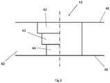
- FIG. 11 shows a sectional view of a through hole 41 in a nickel tube 40, the left half of which is FIG Figure 2 the condition before the laser post-treatment and the right side of the Figure 2 the condition after the laser treatment can be seen.
- the through hole 41 shown was produced by means of three spray etching treatments. This shows accordingly on the left-hand side of the Figure 2 Through hole 41 shown has three areas with different diameters.
- the through hole 41 can be divided into sections 42, 43 and 44.
- section 42 is the section of the cavity which has been produced by means of the first spray etching treatment
- section 43 is the section which has been produced by means of the second spray etching treatment
- section 44 is the section which has been produced by means of the third spray etching treatment.
- the diameters of the sections 43 and 44 which are reduced compared to the first section 42, act like constrictions. These constrictions are removed by means of an engraving laser, ie the sections 43 and 44 are expanded so that they have the same diameter as the section 42, as the right-hand side of FIG Figure 2 can be found.
- the right side of the Figure 2 shows a continuously cylindrical through hole after the laser treatment.
- Figure 3 shows schematically a through hole 41 in a nickel tube 40, the left side of the Figure 3 the through hole 41 before the laser post-treatment and the right side of the Figure 3 shows the through hole 41 after the laser post-treatment.
- This in Figure 3 through hole 41 shown differs from that in FIG Figure 2 through hole shown in that it has a continuously conical cavity.
- the conical shape of the through hole 41 is favored by the different diameters of the sections 42, 43 and 44.
- the edge region of the first section 42 can also be post-treated by means of the laser.
Landscapes
- Chemical & Material Sciences (AREA)
- Engineering & Computer Science (AREA)
- Mechanical Engineering (AREA)
- Materials Engineering (AREA)
- Metallurgy (AREA)
- Organic Chemistry (AREA)
- Chemical Kinetics & Catalysis (AREA)
- General Chemical & Material Sciences (AREA)
- Manufacturing & Machinery (AREA)
- ing And Chemical Polishing (AREA)
- Moulds For Moulding Plastics Or The Like (AREA)
Description
- Die vorliegende Erfindung betrifft ein Verfahren zur Herstellung eines siebförmigen Entformungswerkzeugs, die Schritte umfassend: Bereitstellen eines Nickelrohrs, Abdecken der Oberfläche des Nickelrohrs mit einem Schutzlack, Erzeugen einer Vielzahl von Löchern in dem Schutzlack, zur Bildung einer Ätzmaske auf dem Nickelrohr, Sprühätzen des Nickelrohrs samt Ätzmaske, zur Erzeugung einer Vielzahl von Kavitäten in dem Nickelrohr an den Stellen, an welchen sich die Löcher in der Ätzmaske befinden.
- Zur Herstellung von Haken für mechanische Verschlüsse, wie zum Beispiel Klett- oder Haken-Schlaufenverschlüsse, werden Vorformlinge in Form von auf einem Träger angeordneten Stilen hergestellt. Diese Vorformlinge werden in der Regel mittels einer Formwalze und einer Anpresswalze erzeugt. Dabei kann die Formwalze eine Gießwalze umfassen, auf welcher ein Sieb zum Formen der Stiele angeordnet ist. Zur Herstellung der Stiele wird dann ein thermoplastisches Material in einen Spalt zwischen der Formwalze und der Anpresswalze extrudiert. Die Schmelze erkaltet teilweise in den Formholräumen der Formwalze, welche durch das Sieb gebildet werden. Nach dem Entformen liegen Vorformlinge in Form von Stielen vor, welche von einer Matte beziehungsweise einem Träger emporragen.
- Entscheidend für die Formgebung der Vorformlinge ist das verwendete Sieb. Die Eigenschaften der Vorformlinge können bereits durch das Herstellverfahren des Siebs beeinflusst werden. In einem allgemein bekannten Verfahren zur Siebherstellung wird zunächst ein dünnwandiges Nickelrohr bereitgestellt. In einem nächsten Schritt wird das Nickelrohr mit einem Schutzlack überzogen. Darauf folgend wird der Schutzlack an den Bereichen, an welchen die Sieblöcher erzeugt werden sollen, mittels eines Lasers mit Löchern versehen. Der gelöcherte Schutzlack bildet eine Ätzmaske. Anschließend wird das dünnwandige Nickelrohr gemeinsam mit der Ätzmaske einer Ätzbehandlung unterzogen. Ein Ätzmittel ätzt Löcher in das Nickelrohr an den Stellen, an denen die Ätzmaske Löcher aufweist. Schließlich liegt ein dünnwandiges Nickelsieb vor.
- Da dieses Sieb jedoch noch zu dünn für die Herstellung von Vorformlingen ist, muss es einem weiteren Vernicklungsprozess unterzogen werden. Dabei werden in einem Galvanobad weitere Nickelschichten auf das dünne Nickelsieb aufgetragen. Mit der Zunahme der Wandstärke nimmt auch die Länge der Löcher des Siebs zu. Der Materialauftrag durch Vernicklung kann so lange durchgeführt werden, bis die gewünschte Länge der Durchgangslöcher erreicht ist.
- Da der Materialauftrag und insbesondere die Fortbildung der Löcher nicht unmittelbar zu kontrollieren sind, können die Löcher untereinander Unregelmäßigkeiten aufweisen. Davon ist insbesondere die Form der inneren Oberfläche der Löcher betroffen. Unregelmäßig geformte Löcher haben unregelmäßige Vorformlinge zur Folge.
- Darüber hinaus bilden sich an den Randbereichen der Löcher Radien. Diese Radien sind charakteristisch für den Materialauftrag mittels Galvanobad. Die Radien haben zur Folge, dass Durchgangslöcher in Form von rotationssymmetrischen Hyperboloiden entstehen. Exakte Geometrien, wie zum Beispiel Kanten an den Enden des Durchgangslochs, oder ein über die Länge des Durchgangslochs gesehener konstanter Durchmesser sind somit nicht möglich.
-
DE 196 46 318 A1 zeigt ein rationelles Verfahren zur Herstellung eines Haftverschlußteils aus thermoplastischem Kunststoff gemäß dem Oberbegriff des Anspruchs 1. -
US 2004/0119192 A1 zeigt ein Verfahren zum Herstellen eines Haftverschlußteils. - Ausgehend von dem bekannten Stand der Technik ist es eine Aufgabe der vorliegenden Erfindung, ein verbessertes Verfahren zur Herstellung eines siebförmigen Entformungswerkzeugs anzugeben. Diese Aufgabe wird mittels eines Verfahrens mit den Merkmalen des Anspruchs 1 gelöst. Vorteilhafte Ausgestaltungen ergeben sich aus den Unteransprüchen.
- Entsprechend wird ein Verfahren zur Herstellung eines siebförmigen Entformungswerkzeugs angegeben, welches die folgenden Schritte umfasst: Bereitstellen eines Nickelrohrs, Abdecken der Oberfläche des Nickelrohrs mit einem Schutzlack, Erzeugen einer Vielzahl von Löchern in dem Schutzlack, zur Bildung einer Ätzmaske auf dem Nickelrohr, Sprühätzen des Nickelrohrs samt Ätzmaske, zur Erzeugung einer Vielzahl von Kavitäten in dem Nickelrohr an den Stellen, an welchen sich die Löcher in der Ätzmaske befinden. Erfindungsgemäß folgt dem Sprühätzschritt mindestens ein zweiter Sprühätzschritt, um Kavitäten in Form von Durchgangslöchern zu erzeugen, und die inneren Oberflächen der Kavitäten werden in einem weiteren Schritt mittels eines Lasers behandelt, um aufgrund der aufeinanderfolgenden Sprühätzschritte in den Kavitäten entstandene Verengungen zu entfernen.
- Mit dem vorstehend beschriebenen Verfahren ist es möglich, ein siebförmiges Entformungswerkzeug ohne die Durchführung eines Auftragverfahrens herzustellen. Die Schritte einer Vernickelung, beispielsweise mittels eines Galvanobads, mittels welchem Nickel Schicht für Schicht aufgetragen wird, um ein Nickelrohr mit einer gewünschten Wandstärke zu erhalten, ist nicht erforderlich. Vielmehr wird das Nickelrohr bereits in der gewünschten Endwandstärke bereitgestellt. D.h., die Wandstärke des Nickelrohrs ist festgelegt, bevor die Kavitäten in dem Nickelrohr erzeugt werden. Dadurch lassen sich Formhohlräume in Form von Durchgangslöchern mit konstanter Länge in dem Nickelrohr erzeugen.
- Da das Nickelrohr eingangs bereits seine Endwandstärke aufweist, werden mindestens zwei Sprühätzschritte benötigt, um die Durchgangslöcher in dem Nickelrohr zu erzeugen. Dabei wird mittels jedem Sprühätzschritt sukzessive ein Abschnitt eines Durchgangslochs erzeugt. Bei dem zweiten und jedem weiteren Sprühätzschritt muss das Sprühätzmittel durch den zuvor erzeugten Abschnitt oder die zuvor erzeugten Abschnitte der Kavität hindurchgeführt werden, um die Kavität zu erweitern. Dabei entstehen Übergänge zwischen den einzelnen Abschnitten der Kavität in Form von Verengungen. Dies hat zur Folge, dass der zweite und alle weiteren mittels eines Sprühätzschritts erzeugten Abschnitte der Kavität einen geringeren Durchmesser aufweisen, als der mittels des vorhergehenden Sprühätzschritts erzeugte Abschnitt der Kavität. Durch die mindestens zwei nacheinander ausgeführten Sprühätzschritte entstehen somit stufenförmige Durchgangslöcher in dem Nickelrohr.
- Des Weiteren kann auch die mittels eines Sprühätzschritts erreichbare Abtrag- oder Ätztiefe gegenüber dem vorhergehenden Sprühätzschritt geringer ausfallen, so dass die Länge der mittels der einzelnen Sprühätzschritte erzeugbaren Abschnitte der Kavität sukzessive abnimmt.
- Die nachgeschaltete Laserbehandlung ermöglicht es, die unregelmäßige Oberfläche des mittels der mindestens zwei Sprühätzschritte erzeugten Durchgangslochs zu begradigen. Dadurch ist es möglich, ein Durchgangsloch mit einer glatten inneren Oberfläche bereitzustellen.
- Ein weiterer Vorteil des vorstehend beschriebenen Verfahrens liegt darin, dass Radien an den Enden des Durchgangslochs vermieden bzw. reduziert werden können. Mittels des sukzessiven Abtragverfahrens in Form von mindestens zwei Sprühätzschritten und der nachgeschalteten Lasernachbehandlung können an den Enden der Durchgangslöcher exakte Geometrien, wie zum Beispiel Kanten, erzeugt werden.
- In einer bevorzugten Ausgestaltung wird mittels mindestens dem ersten Sprühätzschritt eine Kavität in Form eines Sacklochs erzeugt. Mittels des letzten Sprühätzschritts erhält die Kavität die Form eines Durchgangslochs. Entsprechend wird mittels des ersten Sprühätzschritts eine Kavität erzeugt, welche von der äußeren Oberfläche des Nickelrohrs radial nach innen ragt, wobei die Tiefe des Abschnitts kleiner als die Wandstärke des Nickelrohrs ist. Frühestens mittels des zweiten Sprühätzschritts wird die Kavität dahingehend erweitert, dass sie von der äußeren Umfangsoberfläche bis hin zur inneren Umfangsoberfläche des Nickelrohrs ragt.
- In einer bevorzugten Ausführungsform verengt sich die Kavität des Durchgangslochs stufenweise, wobei der Durchmesser des mittels des zweiten Sprühätzschritts erzeugbaren Abschnitts der Kavität gegenüber dem vorhergehenden Abschnitt kleiner ist.
- In einer Weiterbildung erfolgt die Laserbehandlung zum Entfernen der Verengungen mittels eines Gravurlasers. Mit einem Gravurlaser ist es möglich, eine glatte Oberfläche auf der Innenseite des Durchgangslochs zu erzeugen. Die mittels der Sprühätzschritte erzeugten Abschnitte des Durchgangslochs mit verschiedenen Durchmessern können dadurch zu einem Abschnitt mit einem einzigen Durchmesser verschmolzen werden. Der Gravurlaser kann von der Außenseite des Nickelrohrs in die Durchgangslöcher eingebracht werden. Die sukzessive Reduktion des Durchmessers der mittels der einzelnen Sprühätzschritte erzeugten Abschnitte der Kavität stellt überstehende Lochränder bereit, deren Oberflächen hin zur Außenseite des Nickelrohrs gerichtet sind. Der Gravurlaser kann diese überstehenden Lochränder erfassen und dadurch den Durchmesser eines Abschnitts der Kavität an den Durchmesser eines angrenzenden Abschnitts der Kavität angleichen.
- Alternativ können mittels des Gravurlasers auch lediglich die Übergänge von einem Abschnitt der Kavität zu einem angrenzenden Abschnitt der Kavität geglättet werden.
- Insgesamt weist der Schritt der Lasernachbehandlung einen vergleichsweise geringen Materialabtrag auf. So wird beim Anpassen der Durchmesser der Abschnitte der Kavität oder beim Glätten der Übergänge zwischen den einzelnen Abschnitten der Kavität nur eine geringe Menge des Nickelrohrs abgetragen. Dadurch fällt die Lasernachbehandlung weniger zeit- und energieintensiv aus als eine Erzeugung eines Durchgangslochs, welche vollständig auf einem Materialabtrag mittels Laserbehandlung basiert.
- In einer weiter bevorzugten Ausführungsform werden mittels der Laserbehandlung zum Entfernen der Verengungen durchgehend zylindrische Kavitäten erzeugt. So können Abschnitte der Kavität, welche durch den zweiten oder spätere Sprühätzschritte erzeugt worden sind, mittels der Laserbehandlung auf den Durchmesser des Mittels des ersten Sprühätzschritts erzeugten Abschnitts aufgeweitet werden, so dass das sukzessiv erzeugte Durchgangsloch in dem Nickelrohr eine durchgehend zylindrische Form aufweist. Auch andere Oberflächenunebenheiten auf der inneren Umfangsoberfläche des Durchgangslochs, welche sich aus Unregelmäßigkeiten der Sprühätzbehandlung ergeben können, können mittels der Laserbehandlung entfernt werden.
- Die zylindrischen Kavitäten bilden Formhohlräume, mittels welchen das siebförmige Entformungswerkzeug zylindrische Vorformlinge herstellen kann. Mittels der Laserbehandlung kann sichergestellt werden, dass die Vielzahl der auf dem siebförmigen Entformungswerkzeug verteilten Formhohlräume eine im Wesentlichen einheitliche zylindrische Form aufweist.
- In einer weiter bevorzugten Weiterbildung werden mittels der Laserbehandlung zum Entfernen der Verengungen durchgehend konische Kavitäten erzeugt. Dabei werden die konischen Kavitäten in Form von Durchgangslöchern derart auf dem Nickelrohr erzeugt, dass sie sich von der äußeren Umfangsoberfläche des Nickelrohrs hin zu der inneren Umfangsoberfläche des Nickelrohrs verjüngen. Die Durchgangslöcher bzw. Formhohlräume erleichtern aufgrund der Konizität das Entformen von mittels den Hohlräumen erzeugten Vorformlingen.
- Überdies bietet sich die Erzeugung von konischen Kavitäten an, da das mittels des mehrstufigen Sprühätzens erzeugte Durchgangsloch aufgrund der Abnahme der Durchmesser der sukzessiv erzeugten Abschnitte der Kavität bereits eine sich stufenweise verjüngende Form aufweist. Zur Begradigung der inneren Umfangsoberfläche des Durchgangslochs ist somit ein vergleichsweise geringer Materialabtrag ausreichend, um eine konische Kavität des Durchgangslochs zu erzeugen.
- In einer weiter bevorzugten Ausgestaltung werden die Löcher auf dem Schutzlack gleichmäßig verteilt, wobei die Löcher untereinander jeweils den gleichen Durchmesser aufweisen. Die gleichmäßige Verteilung der Löcher auf dem Schutzlack hat zur Folge, dass die mittels der mehrstufigen Sprühätzbehandlung erzeugten Kavitäten gleichmäßig auf dem Nickelrohr verteilt sind. Aufgrund des gleichen Durchmessers der Löcher weisen auch die mittels der mehrstufigen Sprühätzbehandlung erzeugten Durchgangslöcher den gleichen Durchmesser auf.
- In einer weiter bevorzugten Ausführungsform werden die Löcher auf dem Schutzlack unregelmäßig verteilt, wobei die Löcher untereinander jeweils den gleichen Durchmesser aufweisen. Die ungleichmäßige Verteilung der Löcher auf dem Schutzlack hat zur Folge, dass die mittels der mehrstufigen Sprühätzbehandlung erzeugten Durchgangslöcher unregelmäßig auf dem Nickelrohr bzw. dem siebförmigen Entformungswerkzeug verteilt sind.
- In einer bevorzugten Ausgestaltung weist das Nickelrohr eine Wandstärke von 150 bis 500 µm auf. Die Wandstärke des Nickelrohrs definiert die Länge der Durchgangslöcher und damit die Länge der mittels des siebförmigen Entformungswerkzeugs entformbaren Vorformlinge. Eine einheitliche Wandstärke des Nickelrohrs stellt sicher, dass die Durchgangslöcher und somit die mittels des siebförmigen Entformungswerkzeugs erzeugbaren Vorformlinge eine einheitliche Länge aufweisen. Umso größer die Wandstärke des Nickelrohrs ist, umso mehr Sprühätzschritte sind nötig, um ein Durchgangsloch in dem Nickelrohr zu erzeugen.
- In einer bevorzugten Ausführungsform beträgt der Durchmesser der Kavitäten nach der Laserbehandlung 100 bis 500 µm. Dieser Durchmesser kann einheitlich über die gesamte Länge eines Durchgangslochs, einschließlich der Endbereiche des Durchgangslochs, bereitgestellt werden. Somit ist es möglich, mittels des siebförmigen Formungswerkzeugs Vorformlinge von einheitlichem Durchmesser herzustellen. Alternativ können auch Vorformlinge hergestellt werden, bei welchen der Durchmesser aufgrund einer Konizität der Durchgangslöcher abnimmt.
- Aufgrund des vorstehend beschriebenen Verfahrens kann der Durchmesser auch in den Endbereichen des Durchgangslochs bereitgestellt werden. Insbesondere kann vermieden werden, dass in den Endbereichen Aufweitungen, beispielsweise in Form von Radien, auftreten.
- In einer Weiterbildung werden 50 bis 500 Löcher pro cm2 auf dem Schutzlack erzeugt. Entsprechend können mittels der mehrstufigen Sprühätzbehandlung 50 bis 500 Durchgangslöcher pro cm2 in dem Nickelrohr erzeugt werden.
- In einer weiter bevorzugten Ausführungsform wird das Nickelrohr in der Endwandstärke des siebförmigen Entformungswerkzeugs bereitgestellt. Entsprechend ist ein Materialabtrag oder ein Materialauftrag in Bezug auf die Wandstärke des Nickelrohrs nicht erforderlich. Die Bearbeitung des Nickelrohrs beschränkt sich im Wesentlichen auf die Erzeugung der Durchgangslöcher mittels der mehrstufigen Sprühätzbehandlung sowie der Lasernachbehandlung.
- Bevorzugte weitere Ausführungsformen und Aspekte der vorliegenden Erfindung werden durch die nachfolgende Beschreibung der Figuren näher erläutert. Dabei zeigen:
- Figur 1
- schematisch ein Ablaufdiagramm eines Verfahrens zur Herstellung eines siebförmigen Entformungswerkzeugs,
- Figur 2
- schematisch eine Schnittansicht eines Durchgangslochs, und
- Figur 3
- schematisch eine Schnittansicht eines Durchgangslochs.
- Im Folgenden werden bevorzugte Ausführungsbeispiele anhand der Figuren beschrieben. Dabei werden gleiche, ähnliche oder gleichwirkende Elemente mit identischen Bezugszeichen bezeichnet. Um Redundanzen zu vermeiden, wird auf eine wiederholte Beschreibung dieser Elemente in der nachfolgenden Beschreibung teilweise verzichtet.
-
Figur 1 ist ein Ablaufdiagramm eines Verfahrens zur Herstellung eines siebförmigen Entformungswerkzeugs zu entnehmen. Zunächst wird ein Nickelrohr mit einer Wandstärke von 300 µm bereitgestellt. Das Nickelrohr wurde zuvor durch ein galvanisches Verfahren erzeugt. Alternativ kann auch ein Kupferrohr zum Einsatz kommen. - Bei Schritt 10 wird die äußere Umfangsoberfläche des Nickelrohrs mit einem Schutzlack abgedeckt. Unter Schritt 12 werden mittels eines Lasers Löcher in dem Schutzlack erzeugt. In Bezug auf den Schutzlack handelt es sich dabei um Durchgangslöcher, durch welche am Grund der Löcher das Nickelrohr freigelegt wird. Die Löcher sind gleichmäßig auf dem Schutzlack verteilt und weisen einen Durchmesser von 250 µm auf. Die Löcher werden in einer Dichte von 200 Stück pro cm2 über den Umfang des Schutzlacks verteilt.
- Die Löcher sind kreisförmig, so dass zylinderförmige Durchgangslöcher in dem Schutzlack entstehen. Alternativ können die Löcher auch eckig ausgeführt sein, so dass drei-, vier-, fünf-, sechseckige Löcher und dergleichen erzeugt werden können. Auch sternförmige, ovale, elliptische und andere Geometrien können für die Löcher infrage kommen. Der mit Löchern versehene Schutzlack wird auch als Ätzmaske bezeichnet.
- Im nächsten Schritt 20 wird das mit der Ätzmaske versehene Nickelrohr einer Sprühätzbehandlung unterzogen. Als Ätzmittel kann beispielsweise FeCl3 zum Einsatz kommen. Der Schutzlack, d.h., die Ätzmaske ist resistent gegen das Sprühätzmittel. In Bezug auf das Nickelrohr hingegen kann sich das Ätzmittel in das Material hineinätzen. Die im Bereich der Löcher der Ätzmaske freiliegenden Bereiche des Nickelrohrs geraten mit dem Ätzmittel in Kontakt, wobei sich das Ätzmittel in das Nickelrohr hineinfrisst und Kavitäten in Form von Sacklöchern bildet. Die Kavitäten weisen an ihrem Randbereich im Wesentlichen die Form der Löcher der Ätzmaske auf. Auch der Durchmesser der Kavitäten entspricht im Wesentlichen dem Durchmesser der Löcher in der Ätzmaske. Die Tiefe der mittels unter Schritt 20 durchgeführten Sprühätzbehandlung beträgt in etwa die Hälfte der Wandstärke des Nickelrohrs, d.h. 150 µm.
- Im nächsten Schritt 22 wird das Nickelrohr samt Ätzmaske einer weiteren Sprühätzbehandlung unterzogen. Dabei frisst sich das Ätzmittel, ausgehend von dem Boden der in dem vorhergehenden Schritt 20 erzeugten Sacklöchern weiter in Bezug auf das Nickelrohr radial nach innen, bis schließlich aus dem Sackloch ein Durchgangsloch gebildet wird.
- Mittels der zweiten Sprühätzbehandlung unter Schritt 22 ist es nicht möglich, die Erweiterung der Kavität nahtlos an das mittels der ersten Sprühätzbehandlung erzeugte Sackloch anzuschließen. Somit kommt es zu einer Verengung der Kavität im Bereich des Übergangs des Abschnitts der Kavität, welcher mittels der ersten Sprühätzbehandlung erzeugt worden ist, zu dem Abschnitt der Kavität, welcher mittels der zweiten Sprühätzbehandlung erzeugt worden ist. D.h., der Abschnitt der Kavität, welcher mittels der zweiten Sprühätzbehandlung erzeugt worden ist, weist einen geringeren Durchmesser auf als der Abschnitt der Kavität, welcher mittels der ersten Sprühätzbehandlung erzeugt worden ist.
- Die vorstehend beschriebene Verengung wird in Schritt 30 mittels einer Lasernachbehandlung entfernt. Dabei kommt ein Gravurlaser zum Einsatz, welcher den Abschnitt der Kavität, welcher mittels der zweiten Sprühätzbehandlung erzeugt worden ist, so weit aufweitet, bis dieser den gleichen Durchmesser wie der Abschnitt der Kavität, welcher mit der ersten Sprühätzbehandlung erzeugt worden ist, aufweist. Durch die Lasernachbehandlung entsteht ein Durchgangsloch, wobei das Durchgangsloch die Form einer durchgehend zylindrischen Kavität aufweist.
- Alternativ können mittels der Lasernachbehandlung auch ein Durchgangsloch mit einer durchgehend konischen Kavität erzeugt werden. Dabei verjüngt sich das Durchgangsloch von der äußeren Umfangsoberfläche des Nickelrohrs hin zu der inneren Umfangsoberfläche des Nickelrohrs.
- Schließlich wird die Ätzmaske entfernt, wodurch ein fertiges siebförmiges Entformungswerkzeug erhalten wird. Alternativ kann die Ätzmaske bereits nach der Sprühätzbehandlung, mittels welcher das Durchgangsloch erzeugt worden ist, entfernt werden.
-
Figur 2 zeigt eine Schnittansicht eines Durchgangslochs 41 in einem Nickelrohr 40, wobei der linken Hälfte derFigur 2 der Zustand vor der Lasernachbehandlung und der rechten Seite derFigur 2 der Zustand nach der Lasernachbehandlung zu entnehmen ist. Das inFigur 2 gezeigte Durchgangsloch 41 wurde mittels drei Sprühätzbehandlungen erzeugt. Entsprechend weist das auf der linken Seite derFigur 2 gezeigte Durchgangsloch 41 drei Bereiche mit unterschiedlichen Durchmessern auf. Das Durchgangsloch 41 kann in die Abschnitte 42, 43 und 44 unterteilt werden. Dabei ist der Abschnitt 42 der Abschnitt der Kavität, welcher mittels der ersten Sprühätzbehandlung erzeugt worden ist, der Abschnitt 43 der Abschnitt, welcher mittels der zweiten Sprühätzbehandlung erzeugt worden ist, und der Abschnitt 44 der Abschnitt, welcher mittels der dritten Sprühätzbehandlung erzeugt worden ist. - Von einer äußeren Umfangsoberfläche 46 des Nickelrohrs 40 hin zu einer inneren Umfangsoberfläche 48 des Nickelrohrs 40 betrachtet, wirken die gegenüber dem ersten Abschnitt 42 verringerten Durchmesser der Abschnitte 43 und 44 wie Verengungen. Diese Verengungen werden mittels eines Gravurlasers entfernt, d.h., die Abschnitte 43 und 44 werden aufgeweitet, so dass sie den gleichen Durchmesser wie der Abschnitt 42 aufweisen, wie der rechten Seite der
Figur 2 zu entnehmen ist. Die rechte Seite derFigur 2 zeigt ein durchgehend zylindrisches Durchgangsloch nach der Lasernachbehandlung. -
Figur 3 zeigt schematisch ein Durchgangsloch 41 in einem Nickelrohr 40, wobei die linke Seite derFigur 3 das Durchgangsloch 41 vor der Lasernachbehandlung und die rechte Seite derFigur 3 das Durchgangsloch 41 nach der Lasernachbehandlung zeigt. Das inFigur 3 gezeigte Durchgangsloch 41 unterscheidet sich von dem inFigur 2 gezeigten Durchgangsloch dadurch, dass es eine durchgehend konische Kavität aufweist. Die konische Form des Durchgangslochs 41 wird durch die unterschiedlichen Durchmesser der Abschnitte 42, 43 und 44 begünstigt. Im Gegensatz zu dem inFigur 2 gezeigten zylindrischen Durchgangsloch muss zur Herstellung des inFigur 3 gezeigten konischen Durchgangslochs auch der Randbereich des ersten Abschnitts 42 mittels des Lasers nachbehandelt werden. - Das in
Figur 3 gezeigte konische Durchgangsloch verjüngt sich ausgehend von der äußeren Umfangsoberfläche 46 des Nickelrohrs 40 hin zu der inneren Umfangsoberfläche 48 des Nickelrohrs 40, wie der rechten Seite derFigur 3 zu entnehmen ist. - Soweit anwendbar, können alle einzelnen Merkmale, die in den einzelnen Ausführungsbeispielen dargestellt sind, miteinander kombiniert und/oder ausgetauscht werden, ohne den Bereich der Erfindung zu verlassen.
-
- 10
- Abdecken
- 12
- Lochen
- 20
- Sprühätzen
- 22
- Sprühätzen
- 30
- Lasern
- 40
- Nickelrohr
- 41
- Durchgangsloch
- 42
- Abschnitt
- 43
- Abschnitt
- 44
- Abschnitt
- 46
- Äußere Umfangsoberfläche
- 48
- Innere Umfangsoberfläche
Claims (12)
- Verfahren zur Herstellung eines siebförmigen Entformungswerkzeugs, die Schritte umfassend:- Bereitstellen eines Nickelrohrs (40),- Abdecken (10) der Oberfläche des Nickelrohrs mit einem Schutzlack,- Erzeugen einer Vielzahl von Löchern (12) in dem Schutzlack, zur Bildung einer Ätzmaske auf dem Nickelrohr (40),- Sprühätzen (20) des Nickelrohrs (40) samt Ätzmaske, zur Erzeugung einer Vielzahl von Kavitäten in dem Nickelrohr (40) an den Stellen, an welchen sich die Löcher in der Ätzmaske befinden,dadurch gekennzeichnet, dass
dem Sprühätzschritt (20) mindestens ein zweiter Sprühätzschritt (22) folgt, um Kavitäten in Form von Durchgangslöchern (41) zu erzeugen, und die inneren Oberflächen der Kavitäten in einem weiteren Schritt mittels eines Lasers behandelt werden (30), um aufgrund der aufeinanderfolgenden Sprühätzschritte (20, 22) in den Kavitäten entstandene Verengungen zu entfernen. - Verfahren nach Anspruch 1, dadurch gekennzeichnet, dass mittels mindestens dem ersten Sprühätzschritt (20) eine Kavität in Form eines Sacklochs erzeugt wird und mittels des letzten Sprühätzschritts (22) die Kavität die Form eines Durchgangslochs (41) erhält.
- Verfahren nach Anspruch 1 oder 2, dadurch gekennzeichnet, dass sich die Kavität des Durchgangslochs (41) stufenweise verengt, wobei der Durchmesser des mittels des zweiten Sprühätzschritts (22) erzeugbaren Abschnitts (43) der Kavität gegenüber dem vorhergehenden Abschnitt (42) kleiner ist.
- Verfahren nach einem der vorhergehenden Ansprüche, dadurch gekennzeichnet, dass die Laserbehandlung (30) zum Entfernen der Verengungen mittels eines Gravurlasers erfolgt.
- Verfahren nach einem der vorhergehenden Ansprüche, dadurch gekennzeichnet, dass mittels der Laserbehandlung (30) zum Entfernen der Verengungen durchgehend zylindrische Kavitäten erzeugt werden.
- Verfahren nach einem der Ansprüche1 bis 4, dadurch gekennzeichnet, dass mittels der Laserbehandlung (30) zum Entfernen der Verengungen durchgehend konische Kavitäten erzeugt werden.
- Verfahren nach einem der vorhergehenden Ansprüche, dadurch gekennzeichnet, dass die Löcher auf dem Schutzlack gleichmäßig verteilt werden, wobei die Löcher untereinander jeweils den gleichen Durchmesser aufweisen.
- Verfahren nach einem der Ansprüche 1-6, dadurch gekennzeichnet, dass die Löcher auf dem Schutzlack unregelmäßig verteilt werden, wobei die Löcher untereinander jeweils den gleichen Durchmesser aufweisen.
- Verfahren nach einem der vorhergehenden Ansprüche, dadurch gekennzeichnet, dass das Nickelrohr (40) eine Wandstärke von 150 bis 500 µm aufweist.
- Verfahren nach einem der vorhergehenden Ansprüche, dadurch gekennzeichnet, dass der Durchmesser der Kavitäten nach der Laserbehandlung (30) 100 bis 500 µm beträgt.
- Verfahren nach einem der vorhergehenden Ansprüche, dadurch gekennzeichnet, dass 50 bis 500 Löcher pro cm2 auf dem Schutzlack erzeugt werden.
- Verfahren nach einem der vorhergehenden Ansprüche, dadurch gekennzeichnet, dass das Nickelrohr (40) in der Endwandstärke des siebförmigen Entformungswerkzeugs bereitgestellt wird.
Applications Claiming Priority (1)
| Application Number | Priority Date | Filing Date | Title |
|---|---|---|---|
| DE102016120409.9A DE102016120409A1 (de) | 2016-10-26 | 2016-10-26 | Verfahren zur Herstellung eines siebförmigen Entformungswerkzeugs |
Publications (2)
| Publication Number | Publication Date |
|---|---|
| EP3315042A1 EP3315042A1 (de) | 2018-05-02 |
| EP3315042B1 true EP3315042B1 (de) | 2021-12-01 |
Family
ID=60382021
Family Applications (1)
| Application Number | Title | Priority Date | Filing Date |
|---|---|---|---|
| EP17198697.9A Active EP3315042B1 (de) | 2016-10-26 | 2017-10-26 | Verfahren zur herstellung eines siebförmigen entformungswerkzeugs |
Country Status (2)
| Country | Link |
|---|---|
| EP (1) | EP3315042B1 (de) |
| DE (1) | DE102016120409A1 (de) |
Family Cites Families (7)
| Publication number | Priority date | Publication date | Assignee | Title |
|---|---|---|---|---|
| FR2639871A1 (fr) * | 1988-12-07 | 1990-06-08 | Piolat Rotary | Cylindre tubulaire d'impression grave chimiquement, et son procede de fabrication |
| DE19646318A1 (de) * | 1996-11-09 | 1998-05-14 | Binder Gottlieb Gmbh & Co | Rationelles Verfahren zur Herstellung eines Haftverschlußteils aus thermoplatischem Kunststoff |
| DE10123206A1 (de) * | 2001-05-12 | 2002-11-28 | Binder Gottlieb Gmbh & Co | Verfahren zum Herstellen eines Haftverschlußteils |
| DE102004016614A1 (de) * | 2004-04-03 | 2005-10-20 | Werthmann Engraving Gmbh | Verfahren zum Herstellen von flächen- und tiefenvariablen Prägewerkzeugen |
| DE102006024014A1 (de) * | 2006-05-23 | 2007-11-29 | Gottlieb Binder Gmbh & Co. Kg | Haftverschlußteil |
| US8790528B2 (en) * | 2007-02-08 | 2014-07-29 | Kleo Kwok | Manufacture filtration elements |
| CN103203968B (zh) * | 2012-01-16 | 2017-01-25 | 昆山允升吉光电科技有限公司 | 一种台阶模板的制作方法 |
-
2016
- 2016-10-26 DE DE102016120409.9A patent/DE102016120409A1/de not_active Withdrawn
-
2017
- 2017-10-26 EP EP17198697.9A patent/EP3315042B1/de active Active
Also Published As
| Publication number | Publication date |
|---|---|
| EP3315042A1 (de) | 2018-05-02 |
| DE102016120409A1 (de) | 2018-04-26 |
Similar Documents
| Publication | Publication Date | Title |
|---|---|---|
| DE102006031326B4 (de) | Formkern und Verfahren zur Herstellung eines Faserverbundbauteils für die Luft- und Raumfahrt | |
| DE102008028337B4 (de) | Verfahren zur Herstellung einer Hohlwelle mit mindestens einem integralen Flansch aus Faserverbundwerkstoff | |
| EP2155418A1 (de) | Verfahren zur herstellung eines gussteils, gussform und damit hergestelltes gussteil | |
| DE10339930A1 (de) | Herstellungsverfahren für Metallschmucktafeln | |
| DE3424276C2 (de) | ||
| DE102012001657B3 (de) | Stanzverfahren | |
| WO2006024281A1 (de) | Verfahren zum herstellen von radnaben-rohlingen auf einer druckumformmaschine | |
| DE102017216579A1 (de) | Fertigungsvorrichtung, insbesondere Montagevorrichtung, Werkstück-Koordinationsvorrichtung, Formwerkzeug, Formwerkzeugeinsatz, Qualitätskontrollvorrichtung oder Einbaulehre, mit Verschleiß- und/oder Manipulationserkennung | |
| EP3315042B1 (de) | Verfahren zur herstellung eines siebförmigen entformungswerkzeugs | |
| DE2624872C3 (de) | Verfahren zum Herstellen von ungeteilten Felgen | |
| EP3175036B1 (de) | Verfahren zur herstelung oder bearbeitung einer walze, walze und funktionsschicht einer walze | |
| EP3114375B1 (de) | Ölabstreifkolbenring und verfahren zur herstellung eines ölabstreifkolbenrings | |
| DE69822852T2 (de) | Herstellen von formvertiefungen | |
| EP1551577B1 (de) | Verfahren und vorrichtung zur herstellung einer luftreifenfelge | |
| DE19628166C2 (de) | Verfahren zur Herstellung eines Stiftes zum Entlüften von Formmulden bei der Ausformung und/oder Vulkanisation von Gummiartikeln | |
| DE69303052T2 (de) | Metallischer Einsatz, insbesondere für Verbindungsstücke | |
| EP2281474A2 (de) | Verfahren zur Herstellung eines Schmuckringes | |
| EP4168225B1 (de) | Herstellungsverfahren eines bauteils mit kühlkanalsystem | |
| DE10236306B4 (de) | Vielstufiges Schmiedeverfahren und entsprechendes Fahrradrahmenteil | |
| DE10206169A1 (de) | Verfahren zum Herstellen eines Plastifizierzylinders mit Innenbeschichtung | |
| EP2991786B1 (de) | Verfahren zur herstellung eines drahtformkörpers aus einem drahtgewebe sowie drahtformkörper | |
| EP3695917B1 (de) | Speisereinsatz, verfahren zur herstellung eines speiserkorpus für den seisereinsatz sowie könig und kernkasten zur herstellung eines speiserkorpus | |
| EP3661719B1 (de) | Verfahren und vorrichtung zum herstellen eines verkleidungsteils eines kraftfahrzeugs, verwendung der vorrichtung | |
| DE2051728C3 (de) | Verfahren zum Herstellen eines Schablonensiebes | |
| DE102006026266B4 (de) | Druckform mit flexibler Oberfläche |
Legal Events
| Date | Code | Title | Description |
|---|---|---|---|
| PUAI | Public reference made under article 153(3) epc to a published international application that has entered the european phase |
Free format text: ORIGINAL CODE: 0009012 |
|
| STAA | Information on the status of an ep patent application or granted ep patent |
Free format text: STATUS: THE APPLICATION HAS BEEN PUBLISHED |
|
| AK | Designated contracting states |
Kind code of ref document: A1 Designated state(s): AL AT BE BG CH CY CZ DE DK EE ES FI FR GB GR HR HU IE IS IT LI LT LU LV MC MK MT NL NO PL PT RO RS SE SI SK SM TR |
|
| AX | Request for extension of the european patent |
Extension state: BA ME |
|
| STAA | Information on the status of an ep patent application or granted ep patent |
Free format text: STATUS: REQUEST FOR EXAMINATION WAS MADE |
|
| 17P | Request for examination filed |
Effective date: 20181102 |
|
| RBV | Designated contracting states (corrected) |
Designated state(s): AL AT BE BG CH CY CZ DE DK EE ES FI FR GB GR HR HU IE IS IT LI LT LU LV MC MK MT NL NO PL PT RO RS SE SI SK SM TR |
|
| GRAP | Despatch of communication of intention to grant a patent |
Free format text: ORIGINAL CODE: EPIDOSNIGR1 |
|
| STAA | Information on the status of an ep patent application or granted ep patent |
Free format text: STATUS: GRANT OF PATENT IS INTENDED |
|
| RIC1 | Information provided on ipc code assigned before grant |
Ipc: A44B 18/00 20060101AFI20210511BHEP Ipc: B29C 43/22 20060101ALI20210511BHEP Ipc: C23F 1/02 20060101ALI20210511BHEP Ipc: B07B 1/46 20060101ALN20210511BHEP |
|
| INTG | Intention to grant announced |
Effective date: 20210602 |
|
| GRAS | Grant fee paid |
Free format text: ORIGINAL CODE: EPIDOSNIGR3 |
|
| GRAA | (expected) grant |
Free format text: ORIGINAL CODE: 0009210 |
|
| STAA | Information on the status of an ep patent application or granted ep patent |
Free format text: STATUS: THE PATENT HAS BEEN GRANTED |
|
| AK | Designated contracting states |
Kind code of ref document: B1 Designated state(s): AL AT BE BG CH CY CZ DE DK EE ES FI FR GB GR HR HU IE IS IT LI LT LU LV MC MK MT NL NO PL PT RO RS SE SI SK SM TR |
|
| REG | Reference to a national code |
Ref country code: GB Ref legal event code: FG4D Free format text: NOT ENGLISH |
|
| REG | Reference to a national code |
Ref country code: AT Ref legal event code: REF Ref document number: 1450951 Country of ref document: AT Kind code of ref document: T Effective date: 20211215 Ref country code: CH Ref legal event code: EP |
|
| REG | Reference to a national code |
Ref country code: DE Ref legal event code: R096 Ref document number: 502017012132 Country of ref document: DE |
|
| REG | Reference to a national code |
Ref country code: IE Ref legal event code: FG4D Free format text: LANGUAGE OF EP DOCUMENT: GERMAN |
|
| REG | Reference to a national code |
Ref country code: SE Ref legal event code: TRGR |
|
| REG | Reference to a national code |
Ref country code: LT Ref legal event code: MG9D |
|
| REG | Reference to a national code |
Ref country code: NL Ref legal event code: MP Effective date: 20211201 |
|
| PG25 | Lapsed in a contracting state [announced via postgrant information from national office to epo] |
Ref country code: RS Free format text: LAPSE BECAUSE OF FAILURE TO SUBMIT A TRANSLATION OF THE DESCRIPTION OR TO PAY THE FEE WITHIN THE PRESCRIBED TIME-LIMIT Effective date: 20211201 Ref country code: LT Free format text: LAPSE BECAUSE OF FAILURE TO SUBMIT A TRANSLATION OF THE DESCRIPTION OR TO PAY THE FEE WITHIN THE PRESCRIBED TIME-LIMIT Effective date: 20211201 Ref country code: FI Free format text: LAPSE BECAUSE OF FAILURE TO SUBMIT A TRANSLATION OF THE DESCRIPTION OR TO PAY THE FEE WITHIN THE PRESCRIBED TIME-LIMIT Effective date: 20211201 Ref country code: BG Free format text: LAPSE BECAUSE OF FAILURE TO SUBMIT A TRANSLATION OF THE DESCRIPTION OR TO PAY THE FEE WITHIN THE PRESCRIBED TIME-LIMIT Effective date: 20220301 |
|
| PG25 | Lapsed in a contracting state [announced via postgrant information from national office to epo] |
Ref country code: PL Free format text: LAPSE BECAUSE OF FAILURE TO SUBMIT A TRANSLATION OF THE DESCRIPTION OR TO PAY THE FEE WITHIN THE PRESCRIBED TIME-LIMIT Effective date: 20211201 Ref country code: NO Free format text: LAPSE BECAUSE OF FAILURE TO SUBMIT A TRANSLATION OF THE DESCRIPTION OR TO PAY THE FEE WITHIN THE PRESCRIBED TIME-LIMIT Effective date: 20220301 Ref country code: LV Free format text: LAPSE BECAUSE OF FAILURE TO SUBMIT A TRANSLATION OF THE DESCRIPTION OR TO PAY THE FEE WITHIN THE PRESCRIBED TIME-LIMIT Effective date: 20211201 Ref country code: HR Free format text: LAPSE BECAUSE OF FAILURE TO SUBMIT A TRANSLATION OF THE DESCRIPTION OR TO PAY THE FEE WITHIN THE PRESCRIBED TIME-LIMIT Effective date: 20211201 Ref country code: ES Free format text: LAPSE BECAUSE OF FAILURE TO SUBMIT A TRANSLATION OF THE DESCRIPTION OR TO PAY THE FEE WITHIN THE PRESCRIBED TIME-LIMIT Effective date: 20211201 |
|
| PG25 | Lapsed in a contracting state [announced via postgrant information from national office to epo] |
Ref country code: NL Free format text: LAPSE BECAUSE OF FAILURE TO SUBMIT A TRANSLATION OF THE DESCRIPTION OR TO PAY THE FEE WITHIN THE PRESCRIBED TIME-LIMIT Effective date: 20211201 |
|
| PG25 | Lapsed in a contracting state [announced via postgrant information from national office to epo] |
Ref country code: SM Free format text: LAPSE BECAUSE OF FAILURE TO SUBMIT A TRANSLATION OF THE DESCRIPTION OR TO PAY THE FEE WITHIN THE PRESCRIBED TIME-LIMIT Effective date: 20211201 Ref country code: SK Free format text: LAPSE BECAUSE OF FAILURE TO SUBMIT A TRANSLATION OF THE DESCRIPTION OR TO PAY THE FEE WITHIN THE PRESCRIBED TIME-LIMIT Effective date: 20211201 Ref country code: RO Free format text: LAPSE BECAUSE OF FAILURE TO SUBMIT A TRANSLATION OF THE DESCRIPTION OR TO PAY THE FEE WITHIN THE PRESCRIBED TIME-LIMIT Effective date: 20211201 Ref country code: PT Free format text: LAPSE BECAUSE OF FAILURE TO SUBMIT A TRANSLATION OF THE DESCRIPTION OR TO PAY THE FEE WITHIN THE PRESCRIBED TIME-LIMIT Effective date: 20220401 Ref country code: EE Free format text: LAPSE BECAUSE OF FAILURE TO SUBMIT A TRANSLATION OF THE DESCRIPTION OR TO PAY THE FEE WITHIN THE PRESCRIBED TIME-LIMIT Effective date: 20211201 Ref country code: CZ Free format text: LAPSE BECAUSE OF FAILURE TO SUBMIT A TRANSLATION OF THE DESCRIPTION OR TO PAY THE FEE WITHIN THE PRESCRIBED TIME-LIMIT Effective date: 20211201 |
|
| REG | Reference to a national code |
Ref country code: DE Ref legal event code: R097 Ref document number: 502017012132 Country of ref document: DE |
|
| PG25 | Lapsed in a contracting state [announced via postgrant information from national office to epo] |
Ref country code: IS Free format text: LAPSE BECAUSE OF FAILURE TO SUBMIT A TRANSLATION OF THE DESCRIPTION OR TO PAY THE FEE WITHIN THE PRESCRIBED TIME-LIMIT Effective date: 20220401 |
|
| PLBE | No opposition filed within time limit |
Free format text: ORIGINAL CODE: 0009261 |
|
| STAA | Information on the status of an ep patent application or granted ep patent |
Free format text: STATUS: NO OPPOSITION FILED WITHIN TIME LIMIT |
|
| PG25 | Lapsed in a contracting state [announced via postgrant information from national office to epo] |
Ref country code: DK Free format text: LAPSE BECAUSE OF FAILURE TO SUBMIT A TRANSLATION OF THE DESCRIPTION OR TO PAY THE FEE WITHIN THE PRESCRIBED TIME-LIMIT Effective date: 20211201 Ref country code: AL Free format text: LAPSE BECAUSE OF FAILURE TO SUBMIT A TRANSLATION OF THE DESCRIPTION OR TO PAY THE FEE WITHIN THE PRESCRIBED TIME-LIMIT Effective date: 20211201 |
|
| 26N | No opposition filed |
Effective date: 20220902 |
|
| PG25 | Lapsed in a contracting state [announced via postgrant information from national office to epo] |
Ref country code: SI Free format text: LAPSE BECAUSE OF FAILURE TO SUBMIT A TRANSLATION OF THE DESCRIPTION OR TO PAY THE FEE WITHIN THE PRESCRIBED TIME-LIMIT Effective date: 20211201 |
|
| PG25 | Lapsed in a contracting state [announced via postgrant information from national office to epo] |
Ref country code: MC Free format text: LAPSE BECAUSE OF FAILURE TO SUBMIT A TRANSLATION OF THE DESCRIPTION OR TO PAY THE FEE WITHIN THE PRESCRIBED TIME-LIMIT Effective date: 20211201 |
|
| REG | Reference to a national code |
Ref country code: CH Ref legal event code: PL |
|
| GBPC | Gb: european patent ceased through non-payment of renewal fee |
Effective date: 20221026 |
|
| PG25 | Lapsed in a contracting state [announced via postgrant information from national office to epo] |
Ref country code: LU Free format text: LAPSE BECAUSE OF NON-PAYMENT OF DUE FEES Effective date: 20221026 |
|
| PG25 | Lapsed in a contracting state [announced via postgrant information from national office to epo] |
Ref country code: LI Free format text: LAPSE BECAUSE OF NON-PAYMENT OF DUE FEES Effective date: 20221031 Ref country code: CH Free format text: LAPSE BECAUSE OF NON-PAYMENT OF DUE FEES Effective date: 20221031 |
|
| PG25 | Lapsed in a contracting state [announced via postgrant information from national office to epo] |
Ref country code: IE Free format text: LAPSE BECAUSE OF NON-PAYMENT OF DUE FEES Effective date: 20221026 Ref country code: GB Free format text: LAPSE BECAUSE OF NON-PAYMENT OF DUE FEES Effective date: 20221026 |
|
| REG | Reference to a national code |
Ref country code: AT Ref legal event code: MM01 Ref document number: 1450951 Country of ref document: AT Kind code of ref document: T Effective date: 20221026 |
|
| PG25 | Lapsed in a contracting state [announced via postgrant information from national office to epo] |
Ref country code: AT Free format text: LAPSE BECAUSE OF NON-PAYMENT OF DUE FEES Effective date: 20221026 |
|
| PG25 | Lapsed in a contracting state [announced via postgrant information from national office to epo] |
Ref country code: HU Free format text: LAPSE BECAUSE OF FAILURE TO SUBMIT A TRANSLATION OF THE DESCRIPTION OR TO PAY THE FEE WITHIN THE PRESCRIBED TIME-LIMIT; INVALID AB INITIO Effective date: 20171026 |
|
| PG25 | Lapsed in a contracting state [announced via postgrant information from national office to epo] |
Ref country code: CY Free format text: LAPSE BECAUSE OF FAILURE TO SUBMIT A TRANSLATION OF THE DESCRIPTION OR TO PAY THE FEE WITHIN THE PRESCRIBED TIME-LIMIT Effective date: 20211201 |
|
| PG25 | Lapsed in a contracting state [announced via postgrant information from national office to epo] |
Ref country code: MK Free format text: LAPSE BECAUSE OF FAILURE TO SUBMIT A TRANSLATION OF THE DESCRIPTION OR TO PAY THE FEE WITHIN THE PRESCRIBED TIME-LIMIT Effective date: 20211201 |
|
| PG25 | Lapsed in a contracting state [announced via postgrant information from national office to epo] |
Ref country code: MT Free format text: LAPSE BECAUSE OF FAILURE TO SUBMIT A TRANSLATION OF THE DESCRIPTION OR TO PAY THE FEE WITHIN THE PRESCRIBED TIME-LIMIT Effective date: 20211201 |
|
| PG25 | Lapsed in a contracting state [announced via postgrant information from national office to epo] |
Ref country code: GR Free format text: LAPSE BECAUSE OF NON-PAYMENT OF DUE FEES Effective date: 20211201 |
|
| PG25 | Lapsed in a contracting state [announced via postgrant information from national office to epo] |
Ref country code: GR Free format text: LAPSE BECAUSE OF NON-PAYMENT OF DUE FEES Effective date: 20211201 |
|
| PGFP | Annual fee paid to national office [announced via postgrant information from national office to epo] |
Ref country code: DE Payment date: 20241022 Year of fee payment: 8 |
|
| PGFP | Annual fee paid to national office [announced via postgrant information from national office to epo] |
Ref country code: BE Payment date: 20241022 Year of fee payment: 8 |
|
| PGFP | Annual fee paid to national office [announced via postgrant information from national office to epo] |
Ref country code: FR Payment date: 20241025 Year of fee payment: 8 |
|
| PGFP | Annual fee paid to national office [announced via postgrant information from national office to epo] |
Ref country code: IT Payment date: 20241031 Year of fee payment: 8 |
|
| PGFP | Annual fee paid to national office [announced via postgrant information from national office to epo] |
Ref country code: SE Payment date: 20241023 Year of fee payment: 8 |
|
| PGFP | Annual fee paid to national office [announced via postgrant information from national office to epo] |
Ref country code: TR Payment date: 20241017 Year of fee payment: 8 |