EP3314139B1 - Kupplungseinrichtung mit axial wirkender fluidfördereinrichtung - Google Patents
Kupplungseinrichtung mit axial wirkender fluidfördereinrichtung Download PDFInfo
- Publication number
- EP3314139B1 EP3314139B1 EP16739405.5A EP16739405A EP3314139B1 EP 3314139 B1 EP3314139 B1 EP 3314139B1 EP 16739405 A EP16739405 A EP 16739405A EP 3314139 B1 EP3314139 B1 EP 3314139B1
- Authority
- EP
- European Patent Office
- Prior art keywords
- clutch
- fluid
- conveying
- conveying device
- clutch device
- Prior art date
- Legal status (The legal status is an assumption and is not a legal conclusion. Google has not performed a legal analysis and makes no representation as to the accuracy of the status listed.)
- Active
Links
Images


Classifications
-
- F—MECHANICAL ENGINEERING; LIGHTING; HEATING; WEAPONS; BLASTING
- F16—ENGINEERING ELEMENTS AND UNITS; GENERAL MEASURES FOR PRODUCING AND MAINTAINING EFFECTIVE FUNCTIONING OF MACHINES OR INSTALLATIONS; THERMAL INSULATION IN GENERAL
- F16D—COUPLINGS FOR TRANSMITTING ROTATION; CLUTCHES; BRAKES
- F16D25/00—Fluid-actuated clutches
- F16D25/12—Details not specific to one of the before-mentioned types
- F16D25/123—Details not specific to one of the before-mentioned types in view of cooling and lubrication
-
- F—MECHANICAL ENGINEERING; LIGHTING; HEATING; WEAPONS; BLASTING
- F16—ENGINEERING ELEMENTS AND UNITS; GENERAL MEASURES FOR PRODUCING AND MAINTAINING EFFECTIVE FUNCTIONING OF MACHINES OR INSTALLATIONS; THERMAL INSULATION IN GENERAL
- F16D—COUPLINGS FOR TRANSMITTING ROTATION; CLUTCHES; BRAKES
- F16D13/00—Friction clutches
- F16D13/22—Friction clutches with axially-movable clutching members
- F16D13/38—Friction clutches with axially-movable clutching members with flat clutching surfaces, e.g. discs
- F16D13/52—Clutches with multiple lamellae ; Clutches in which three or more axially moveable members are fixed alternately to the shafts to be coupled and are pressed from one side towards an axially-located member
-
- F—MECHANICAL ENGINEERING; LIGHTING; HEATING; WEAPONS; BLASTING
- F16—ENGINEERING ELEMENTS AND UNITS; GENERAL MEASURES FOR PRODUCING AND MAINTAINING EFFECTIVE FUNCTIONING OF MACHINES OR INSTALLATIONS; THERMAL INSULATION IN GENERAL
- F16D—COUPLINGS FOR TRANSMITTING ROTATION; CLUTCHES; BRAKES
- F16D13/00—Friction clutches
- F16D13/58—Details
- F16D13/72—Features relating to cooling
-
- F—MECHANICAL ENGINEERING; LIGHTING; HEATING; WEAPONS; BLASTING
- F16—ENGINEERING ELEMENTS AND UNITS; GENERAL MEASURES FOR PRODUCING AND MAINTAINING EFFECTIVE FUNCTIONING OF MACHINES OR INSTALLATIONS; THERMAL INSULATION IN GENERAL
- F16D—COUPLINGS FOR TRANSMITTING ROTATION; CLUTCHES; BRAKES
- F16D13/00—Friction clutches
- F16D13/58—Details
- F16D13/74—Features relating to lubrication
Definitions
- the present invention relates to a clutch device for transmitting a torque according to the preamble of patent claim 1.
- wet couplings are preferably used that are connected to a fluid supply.
- a special design of wet clutches are multi-plate clutches in which an oil-like fluid is radially distributed within the clutch by means of paddle wheels.
- the aim here is to provide a solution that is as simple to manufacture as possible and therefore inexpensive.
- a delivery device for delivering a fluid flow in the axial direction of the axis of rotation is provided in a fluid line within the coupling device.
- the fluid is generally an oil used in the coupling device, which is used, for example, for lubrication and cooling. If the fluid is now conveyed through the fluid line, fluid losses occur in particular on the sections of the coupling device which are moved relative to one another. This occurs in particular when rotating and stationary components are moved relative to one another. This shows that fluid stagnation occurs in front of the rotating sections of the fluid line, thereby promoting an undesired outflow of the fluid in the radial direction.
- the accumulated fluid is accelerated in the circumferential direction, so that the centrifugal forces that occur additionally promote the radial outflow.
- Both effects mean that the fluid is only conveyed through the rotating sections of the fluid line with high losses and resistances and that the sections of the coupling device lying behind in the flow direction are not always adequately supplied with fluid.
- the fluid flow can now be increased in the axial direction, that is to say parallel to the axis of rotation of the coupling device, and the fluid flow can thus also be kept sufficiently large in the moving sections of the fluid line.
- the coupling device is particularly preferably arranged as a separating clutch in a hybrid module. This makes it possible to always supply the more complex fluid lines within hybrid modules with fluid to a sufficient extent.
- the conveying device is arranged at least on a first or second coupling side and thereby the conveyed device
- the amount of fluid is speed-dependent.
- the fluid loss occurs in particular when sections of the coupling device are moved relative to one another.
- a conveying device to avoid the loss of fluid preferably only has to be activated when this relative movement occurs.
- the advantage of arranging the conveying device on a rotating first or second coupling side is that the energy required for the operation of the conveying device can only be applied if a fluid loss can actually be prevented or reduced. The conveying effect of the conveyor is not required at standstill.
- Multi-plate clutches and in particular load clutches are suitable for the use of the coupling device, in which the fluid to be delivered is an oil.
- Such multi-plate clutches or wet clutches are available in numerous variants and, due to the fluid supply, are particularly thermally and mechanically loadable.
- the conveyor device has at least one rotor or stator blade.
- the fluid can be conveyed in the axial direction of the coupling device on account of the suitable setting angle of the rotor blade.
- the rotor blade exerts a conveying force on the fluid, which has at least one force component directed in the axial direction.
- the fluid can also initially be accelerated in the circumferential direction by means of a rotor blade. After this initial acceleration in the circumferential direction, at least one stator blade can then be provided, onto which the fluid accelerated in the circumferential direction occurs and thereby deflects in the axial direction. In this way too, an axial conveying force can be exerted on the fluid with a combination of rotor and stator blades.
- At least the rotor or the stator blade in the rotating state exerts a conveying force on the fluid in the axial direction.
- the rotor blade can also interact with the stator blade in order to exert an axial conveying force in this way.
- the delivery device has a plurality of moving rotor blades, which are preferably arranged on a segment of a circle around the axis of rotation of the coupling device.
- the number of stator blades can advantageously be increased accordingly.
- the rotor or stator blades are preferably arranged in a circle on a circle segment.
- the conveying device can be designed, for example, as a one-piece annular disk with molded and angled rotor blades and can be produced in a single manufacturing process, for example as a plastic injection molded part.
- the conveyor can thus be manufactured particularly cost-effectively.
- the conveying device is arranged in a flow direction of the fluid in the area in front of axial fluid passage openings of sections of the fluid line that are moved relative to one another.
- sections of the fluid line that are moved relative to one another build up of fluid as soon as the sections are moved relative to one another. It is therefore particularly efficient to arrange the conveying device precisely at this point and to exert the axial conveying force on the fluid at these points, as a result of which the accumulation of the fluid in front of the moving fluid passage openings is effectively counteracted. As a result, more fluid can pass through the fluid passage openings and the portions of the coupling device lying behind are better supplied with fluid.
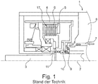
- FIG. 1 A coupling device 1 assumed to be known for transmitting a torque about an axis of rotation 2 is shown.
- the coupling device 1 has a first coupling side 3, which is designed as a rotating shaft.
- the clutch device 1 has a second clutch side 4, wherein a torque transmission between the first clutch side 3 and the second clutch side 4 takes place via friction partners 5.
- the friction partners 5 are designed as multi-plate clutches, which can be brought into frictional engagement with one another in the axial direction when a contact pressure is appropriately exerted and thereby transmit a torque between the first and second clutch sides.
- the coupling device 1 has a fluid line 7, via which a fluid is introduced into a housing 8 of the coupling device 1.
- the arrows shown schematically show the direction and strength of the fluid flow. It can be seen that a fluid loss in the radial direction occurs between a stationary guide plate 9 on the housing side and a rotating section 10 of the second coupling side 4.
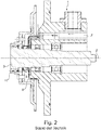
- Fig. 2 shows another known as known coupling device 1 again in an enlarged and only partially shown axial sectional view.
- the desired fluid flow is shown by arrows in the upper region of the axis of rotation 2.
- the actually occurring fluid flow is shown in the lower half of the sectional view, again clearly showing that after passing the guide plate 9, a partial flow of the fluid flows downward in the radial direction and thus only a significantly reduced fluid flow actually passes through the fluid passage opening 11.
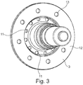
- Fig. 3 shows a perspective view of the first coupling side, which is designed as a rotating shaft with an integrally formed flange 12. Both fluid passage openings 11 and fastening bores 13 are provided in the flange 12, each of which are arranged on a segment of a circle and distributed uniformly over the circumference.
- the Fig. 4 shows an axial sectional view through a coupling device 1.
- a conveying device 14 is arranged in the fluid line 7 immediately behind the guide plate 9, which conveys the inflowing fluid through the fluid passage opening 11 into the coupling device 1.
- the conveying device 14 is fixedly connected via the fastening bore 13 to the first coupling side 3, which is designed as a shaft, and moves with it in rotation.
- the conveyor 14 is shown in isolation in a perspective view.
- the conveyor device 14 has openings 15 on the outer circumference, which enable a connection to the first coupling side 3.
- the number and position of the openings 15 are selected so that they correspond to the fastening bores 13 and can be connected, for example, by means of rivets.
- the conveying device 14 has a plurality of rotor blades 16, which are angled such that when the conveying device 14 rotates about the axis of rotation 2, at least one axial conveying force exerts on the fluid.
- the conveying force has an axially parallel force component directed to the left in the image plane, so that the To assist flow of the fluid through the fluid passage opening 11.
- the oiling of the entire coupling device with the fluid is improved since significantly more fluid is conveyed into the area behind the fluid passage openings 11.
- FIG. 5 A coupling device 1 is again partially shown in an axial sectional view.
- This view clearly shows that the conveying device 14 can be integrated into the coupling device 1 in a particularly simple manner. It is particularly advantageously provided that the rotor blades 16 are arranged directly in front of the fluid passage opening 11, so that the conveying force can exert on the fluid in the axial direction in a particularly efficient manner.
- the conveyor 14 is made of a thin sheet or as a one-piece plastic part that requires only minimal installation space and is flush with the flange 12 of the first coupling side.
- the rotor blades 16 protrude into the installation space immediately in front of the fluid passage opening 11. As shown by the arrows, no fluid loss or only extremely slight fluid loss occurs in the radial direction in this embodiment as well, since the fluid flow is supported in the axial direction by the conveying device 14.
- FIG. 6 again the first coupling side 3 in a perspective view.
- the conveying device 14 is arranged on the first coupling side 3, the fastening bores 13 and the openings 15 being aligned with one another and being able to be connected to one another, for example, by rivets or screws (not shown).
- the rotor blades 16 which are employed are each arranged directly in front of the fluid passage openings 11 in order to achieve the most efficient possible fluid delivery by efficiently exerting the conveying force on the fluid.
- the conveying device 14 requires only an extremely small installation space and can therefore be integrated into almost all existing coupling devices in a particularly simple manner.
- the conveyor can be manufactured with very little effort and thus inexpensively.
Landscapes
- Engineering & Computer Science (AREA)
- General Engineering & Computer Science (AREA)
- Mechanical Engineering (AREA)
- Hydraulic Clutches, Magnetic Clutches, Fluid Clutches, And Fluid Joints (AREA)
Description
- Die vorliegende Erfindung betrifft eine Kupplungseinrichtung zur Übertragung eines Drehmoments gemäß dem Oberbegriff des Patentanspruchs 1.
- Derartige Kupplungseinrichtungen sind im Stand der Technik in zahlreichen Ausführungsformen bekannt. Bei bestimmten Anwendungsfällen kommen bevorzugt Nasskupplungen zum Einsatz, die mit einer Fluidversorgung verbunden sind. Eine besondere Bauform von Nasskupplungen stellen Lamellenkupplungen dar, bei denen ein ölförmiges Fluid mittels Schaufelrädern innerhalb der Kupplung radial verteilt wird.
- Bei den bekannten Kupplungseinrichtungen ist jedoch zu beobachten, dass die Ölversorgung nicht in allen Bereichen der Kupplungseinrichtung und bei allen Betriebszuständen in dem gewünschten Maß sichergestellt ist. So kann es vorkommen, dass weiter entfernte Abschnitte wie bspw. entfernter liegende Lager nicht ausreichend mit dem Fluid versorgt werden.
- Aus jeder der
DE 11 2013 000 259 T5 , derEP 1 930 613 A1 , derDE 31 33 478 A1 , derDE 11 2010 003 465 T5 , derDE 100 49 459 A1 , derDE 10 2014 205 380 A1 und derJP S59 131035 A - Aufgabe der vorliegenden Erfindung ist es daher, die sich aus dem Stand der Technik ergebenden Probleme zumindest teilweise zu lösen und insbesondere eine Kupplungseinrichtung mit einer verbesserten Fluidversorgung anzugeben. Hierbei wird angestrebt, eine möglichst einfach zu fertigende und damit kostengünstige Lösung bereitzustellen.
- Diese Aufgaben werden mit einer Vorrichtung gemäß den Merkmalen des Patentanspruchs 1 gelöst. Weitere vorteilhafte Ausgestaltungen der Erfindung sind in den abhängig formulierten Patentansprüchen angegeben. Es ist darauf hinzuweisen, dass die in den abhängig formulierten Patentansprüchen einzeln aufgeführten Merkmale in beliebiger technologisch sinnvoller Weise miteinander kombiniert werden können und weitere Ausgestaltungen der Erfindung definieren. Darüber hinaus werden in den Patentansprüchen angegebenen Merkmale in der Beschreibung näher präzisiert und erläutert, wobei weitere bevorzugte Ausführungsbeispiele der Erfindung dargestellt werden.
- In einer Fluidleitung innerhalb der Kupplungseinrichtung ist eine Fördereinrichtung zur Förderung eines Fluidstroms in axialer Richtung der Drehachse vorgesehen. Bei einer Fluidleitung, welche sich sowohl durch ein feststehendes Gehäuse als auch durch wenigstens die sich drehenden ersten oder zweiten Kupplungsseiten erstreckt, kann es zu unerwünschten Fluidaustritten kommen. Bei dem Fluid handelt es sich in der Regel um ein in der Kupplungseinrichtung verwendetes Öl, das bspw. zur Lubrikation und Kühlung dient. Wird nun das Fluid durch die Fluidleitung gefördert, kommt es insbesondere an den relativ zueinander bewegten Abschnitten der Kupplungseinrichtung zu Fluidverlusten. Dies tritt insbesondere dann auf, wenn rotierende und feststehende Bauteile relativ zueinander bewegt werden. Hierbei zeigt es sich, dass es vor den rotierenden Abschnitten der Fluidleitung zu Fluidstauungen kommt, wodurch ein unerwünschtes Abströmen des Fluids in radialer Richtung begünstigt wird. Zusätzlich zu dem beschriebenen Staueffekt wird das gestaute Fluid noch in Umfangsrichtung beschleunigt, wodurch die auftretenden Fliehkräfte das radiale Abströmen zusätzlich begünstigen. Beide Effekte führen dazu, dass das Fluid nur mit hohen Verlusten und Widerständen durch die rotierenden Abschnitte der Fluidleitung gefördert wird und die in Strömungsrichtung gesehen dahinter liegenden Abschnitte der Kupplungseinrichtung nicht immer ausreichend mit Fluid versorgt werden.
- Durch die Verwendung einer Fördereinrichtung innerhalb der Kupplungseinrichtung kann der Fluidstrom nun in axialer Richtung, das heißt parallel zur Drehachse der Kupplungseinrichtung, verstärkt und damit der Fluidstrom auch in den bewegten Abschnitten der Fluidleitung ausreichend groß gehalten werden.
- Besonders bevorzugt ist die Kupplungseinrichtung als Trennkupplung in einem Hybridmodul angeordnet. Dies ermöglicht es, auch die komplizierteren Fluidleitungen innerhalb von Hybridmodulen in einem stets ausreichenden Maß mit Fluid zu versorgen.
- Besonders vorteilhaft ist es auch, wenn zudem die Fördereinrichtung wenigstens an einer ersten oder zweiten Kupplungsseite angeordnet und dadurch die geförderte Fluidmenge drehzahlabhängig ist. Wie bereits zuvor beschrieben, tritt der Fluidverlust insbesondere dann auf, wenn Abschnitte der Kupplungseinrichtung relativ zueinander bewegt werden. Dies bedeutet im Umkehrschluss, dass eine Fördereinrichtung zur Vermeidung des Fluidverlusts vorzugsweise nur dann aktiviert sein muss, wenn diese Relativbewegung auftritt. Der Vorteil der Anordnung der Fördereinrichtung an einer sich drehenden ersten oder zweiten Kupplungsseite liegt darin, dass die für den Betrieb der Fördereinrichtung erforderliche Energie nur dann aufzubringen ist, wenn tatsächlich ein Fluidverlust zu verhindern bzw. zu reduzieren ist. Im Stillstand wird die Förderwirkung der Fördereinrichtung nicht benötigt.
- Für den Einsatz der Kupplungseinrichtung sind Lamellenkupplungen und insbesondere Lastkupplungen geeignet, bei denen das zu fördernde Fluid ein Öl ist. Solche Lamellenkupplungen bzw. Nasskupplungen sind in zahlreichen Varianten verfügbar und aufgrund der Fluidversorgung in besonderem Maße thermisch und mechanisch belastbar.
- Erfindungsgemäß weist die Fördereinrichtung wenigstens eine Rotor- oder Statorschaufel auf. So kann schone mit nur einer rotierenden Rotorschaufel das Fluid aufgrund des geeigneten Anstellwinkels der Rotorschaufel in axialer Richtung der Kupplungseinrichtung gefördert werden. Hierbei übt die Rotorschaufel eine Förderkraft auf das Fluid aus, die wenigstens eine in axialer Richtung gerichtete Kraftkomponente aufweist. Alternativ zu den direkten Krafteinwirkungen durch die Rotorschaufel mit einer axialen Kraftkomponente kann das Fluid durch eine Rotorschaufel auch zunächst in Umfangsrichtung beschleunigt werden. Nach dieser anfänglichen Beschleunigung in Umfangsrichtung kann dann wenigstens eine Statorschaufel vorgesehen sein, auf die das in Umfangsrichtung beschleunigte Fluid auftritt und dabei in axialer Richtung umlenkt. Auch auf diese Weise kann mit einer Kombination von Rotor- und Statorschaufel eine axiale Förderkraft auf das Fluid ausgeübt werden.
- Bei einer besonders einfachen Ausführungsform ist vorgesehen, dass wenigstens die Rotor- oder die Statorschaufel im drehenden Zustand in axialer Richtung eine Förderkraft auf das Fluid ausübt. Alternativ kann aber auch die Rotorschaufel mit der Statorschaufel zusammenwirken, um auf diese Weise eine axiale Förderkraft auszuüben.
- Zur Verbesserung der Förderleistung ist zudem vorgesehen, dass die Fördereinrichtung eine Mehrzahl bewegter Rotorschaufeln aufweist, die vorzugsweise auf einem Kreissegment um die Drehachse der Kupplungseinrichtung angeordnet sind. Für den Fall, dass Rotorschaufeln und Statorschaufeln zusammenwirken, kann in vorteilhafter Weise auch die Anzahl der Statorschaufeln entsprechend erhöht werden. Vorzugsweise sind dabei die Rotor- bzw. Statorschaufeln kreisförmig auf einem Kreissegment angeordnet.
- Fertigungstechnisch ist es günstig, die Fördereinrichtung aus Kunststoff oder Metall zu fertigen. Die Fördereinrichtung kann bspw. als einteilige ringförmige Scheibe mit angeformten und abgewinkelten Rotorschaufeln ausgebildet werden und in einem einzigen Herstellungsvorgang als bspw. Kunststoffspritzgussteil hergestellt werden. Damit kann die Fördereinrichtung besonders kostengünstig hergestellt werden.
- Schließlich ist vorgesehen, dass die Fördereinrichtung in einer Strömungsrichtung des Fluids im Bereich vor axialen Fluiddurchtrittsöffnungen von relativ zueinander bewegten Abschnitten der Fluidleitung angeordnet ist. Wie bereits zuvor beschrieben, kommt es an solchen relativ zueinander bewegten Abschnitten der Fluidleitung zu Anstauungen des Fluids, sobald die Abschnitte relativ zueinander bewegt sind. Von daher ist es besonders effizient, genau an dieser Stelle die Fördereinrichtung anzuordnen und die axiale Förderkraft an diesen Stellen auf das Fluid auszuüben, wodurch den Anstauungen des Fluids vor den bewegten Fluiddurchtrittsöffnungen effektiv entgegengewirkt wird. Im Ergebnis kann mehr Fluid durch die Fluiddurchtrittsöffnungen hindurchtreten und die dahinter liegenden Abschnitte der Kupplungseinrichtung werden besser mit Fluid versorgt.
- Die Erfindung sowie das technische Umfeld werden nachfolgend anhand der Figuren näher erläutert. Es ist darauf hinzuweisen, dass die Figuren besonders bevorzugte Ausführungsvarianten der Erfindung zeigen, auf diese jedoch nicht beschränkt ist. In der Zeichnung zeigt schematisch:
- Fig. 1:
- eine axiale Schnittansicht einer als bekannt angenommenen Kupplungseinrichtung,
- Fig.2:
- eine teilweise dargestellte axiale Schnittansicht einer als bekannt angenommenen Kupplungseinrichtung nach dem Stand der Technik mit aufgezeigter Fluidströmung,
- Fig. 3:
- eine perspektivische Darstellung einer drehenden Welle,
- Fig.4:
- eine axiale Schnittansicht einer Kupplungseinrichtung mit einer perspektivisch dargstellten Fördereinrichtung
- Fig. 5:
- eine teilweise axiale Schnittansicht einer Kupplungseinrichtung, und
- Fig. 6:
- eine perspektivische Darstellung einer Fördereinrichtung mit einer drehenden Welle.
- In
Fig. 1 ist eine als bekannt angenommene Kupplungseinrichtung 1 zur Übertragung eines Drehmoments um eine Drehachse 2 dargestellt. Die Kupplungseinrichtung 1 weist eine erste Kupplungsseite 3 auf, die als drehende Welle ausgebildet ist. - Weiterhin weist die Kupplungseinrichtung 1 eine zweite Kupplungsseite 4 auf, wobei eine Drehmomentübertragung zwischen der ersten Kupplungsseite 3 und der zweiten Kupplungsseite 4 über Reibpartner 5 erfolgt. Die Reibpartner 5 sind als Lamellenkupplung ausgebildet, die bei entsprechender Ausübung einer Anpresskraft in axialer Richtung in Reibeingriff miteinander bringbar sind und dadurch ein Drehmoment zwischen der ersten und zweiten Kupplungsseite übertragen. Weiterhin weist die Kupplungseinrichtung 1 eine Fluidleitung 7 auf, über die ein Fluid in ein Gehäuse 8 der Kupplungseinrichtung 1 eingeleitet wird. Die dargestellten Pfeile geben schematisch die Richtung und Stärke des Fluidstroms wieder. Dabei ist erkennbar, dass zwischen einem gehäuseseitigen feststehenden Leitblech 9 und einem rotierenden Abschnitt 10 der zweiten Kupplungsseite 4 ein Fluidverlust in radialer Richtung auftritt.
- Zu einer Fluiddurchtrittsöffnung 11 in der ersten Kupplungsseite 3 gelangt somit nur ein sehr stark reduzierter Teil des Fluidstroms, wodurch die linksseitig der Fluiddurchtrittsöffnung 11 liegenden Abschnitte der Kupplungseinrichtung 1 nur unzureichend mit Fluid versorgt werden.
-
Fig. 2 zeigt eine andere als bekannt angenommene Kupplungseinrichtung 1 noch einmal in einer vergrößerten und nur teilweise dargestellten axialen Schnittansicht. Im oberen Bereich der Drehachse 2 ist der gewünschte Fluidstrom mittels Pfeilen dargestellt. In der unteren Hälfte der Schnittansicht ist der tatsächlich auftretende Fluidstrom gezeigt, wobei wiederum gut erkennbar ist, dass nach dem Passieren des Leitblechs 9 ein Teilstrom des Fluids in radialer Richtung nach unten abfließt und somit nur ein deutlich verringerter Fluidstrom tatsächlich durch die Fluiddurchtrittsöffnung 11 hindurchtritt. -
Fig. 3 zeigt eine perspektivische Ansicht der ersten Kupplungsseite, die als drehende Welle mit einem angeformten Flansch 12 ausgebildet ist. In dem Flansch 12 sind sowohl Fluiddurchtrittsöffnungen 11 als auch Befestigungsbohrungen 13 vorgesehen, die jeweils auf einem Kreissegment gleichmäßig über den Umfang verteilt angeordnet sind. - Die
Fig. 4 zeigt eine axiale Schnittansicht durch eine Kupplungseinrichtung 1. Hierbei ist in der Fluidleitung 7 unmittelbar hinter dem Leitblech 9 eine Fördereinrichtung 14 angeordnet, die das zuströmende Fluid durch die Fluiddurchtrittsöffnung 11 in die Kupplungseinrichtung 1 fördert. Die Fördereinrichtung 14 ist über die Befestigungsbohrung 13 mit der als Welle ausgebildeten ersten Kupplungsseite 3 fest verbunden und bewegt sich rotierend mit dieser mit. Durch Ausübung einer Förderkraft in axialer Richtung parallel zur Drehachse 2 auf das Fluid wird dessen Durchströmung durch die Fluiddurchtrittsöffnung 11 verbessert. Ein Anstauen des Fluids vor der Fluiddurchtrittsöffnung 11 wird damit wirksam vermieden. Gleichzeitig kann die radiale Abströmung des Fluids zwischen dem rotierenden Abschnitt 10 und dem Leitblech 9 mit der Fördereinrichtung 14 signifikant reduziert oder ganz vermieden werden. Im unteren Bereich derFig. 4 ist die Fördereinrichtung 14 in Alleinstellung in einer perspektivischen Ansicht dargestellt. Die Fördereinrichtung 14 weist am äußeren Umfang Durchbrüche 15 auf, die eine Verbindung mit der ersten Kupplungsseite 3 ermöglichen. Hierbei ist die Anzahl und Lage der Durchbrüche 15 so gewählt, dass diese mit den Befestigungsbohrungen 13 korrespondieren und bspw. mittels Nieten verbunden werden können. Weiterhin weist die Fördereinrichtung 14 eine Mehrzahl von Rotorschaufeln 16 auf, die so angewinkelt sind, dass bei einer Rotation der Fördereinrichtung 14 um die Drehachse 2 wenigstens eine axiale Förderkraft auf das Fluid ausüben. Die Förderkraft weist dazu eine in der Bildebene nach links gerichtete achsparallele Kraftkomponente aufweist, um damit das Durchströmen des Fluids durch die Fluiddurchtrittsöffnung 11 zu unterstützen. Die Beölung der gesamten Kupplungseinrichtung mit dem Fluid wird dadurch verbessert, da wesentlich mehr Fluid in den Bereich hinter die Fluiddurchtrittsöffnungen 11 gefördert wird. - In
Fig. 5 ist eine Kupplungseinrichtung 1 nochmals teilweise in einer axialen Schnittansicht dargestellt. Gut erkennbar ist bei dieser Ansicht, dass die Fördereinrichtung 14 besonders einfach in die Kupplungseinrichtung 1 integriert werden kann. Besonders vorteilhaft ist dabei vorgesehen, dass die Rotorschaufeln 16 unmittelbar vor der Fluiddurchtrittsöffnung 11 angeordnet sind, damit in besonders effizienter Weise die Förderkraft in axialer Richtung auf das Fluid ausüben können. Die Fördereinrichtung 14 ist aus einem dünnen Blech oder als einteiliges Kunststoffteil gefertigt, das nur minimalen Bauraum benötigt und bündig am Flansch 12 der ersten Kupplungsseite anliegt. Dabei ragen die angestellten Rotorschaufeln 16 in dem Bauraum unmittelbar vor der Fluiddurchtrittsöffnung 11 hinein. Wie anhand der Pfeile dargestellt, tritt auch bei dieser Ausführungsform kein Fluidverlust oder nur äußerst geringer Fluidverlust in radialer Richtung auf, da der Fluidstrom in axialer Richtung durch die Fördereinrichtung 14 unterstützt wird. - Schließlich zeigt
Fig. 6 nochmals die erste Kupplungsseite 3 in einer perspektivischen Ansicht. Auf der ersten Kupplungsseite 3 ist die Fördereinrichtung 14 angeordnet, wobei die Befestigungsbohrungen 13 und die Durchbrüche 15 miteinander fluchten und bspw. durch nicht dargestellte Nieten oder Schrauben miteinander verbunden werden können. Gut erkennbar ist in dieser Ansicht auch, dass die angestellten Rotorschaufeln 16 jeweils unmittelbar vor den Fluiddurchtrittsöffnungen 11 angeordnet sind, um eine möglichst effiziente Fluidförderung durch eine effiziente Ausübung der Förderkraft auf das Fluid zu erreichen. Wie zu sehen ist, benötigt die Fördereinrichtung 14 nur einen äußerst geringen Bauraum und kann somit in nahezu alle bestehenden Kupplungseinrichtungen in besonders einfacher Weise integriert werden. Zudem kann die Fördereinrichtung mit einem äußerst geringen Aufwand und damit kostengünstig hergestellt werden. -
- 1
- Kupplungseinrichtung
- 2
- Drehachse
- 3
- Erste Kupplungsseite
- 4
- Zweite Kupplungsseite
- 5
- Erster Reibpartner
- 6
- Lamellenkupplung
- 7
- Fluidleitung
- 8
- Gehäuse
- 9
- Leitblech
- 10
- Rotierender Abschnitt
- 11
- Fluiddurchtrittsöffnung
- 12
- Flansch
- 13
- Befestigungsbohrung
- 14
- Fördereinrichtung
- 15
- Durchbruch
- 16
- Rotorschaufel
- 17
- Zweiter Reibpartner
Claims (7)
- Kupplungseinrichtung (1) zum Übertragen eines Drehmoments um eine Drehachse (2) zwischen einer ersten Kupplungsseite (3) und einer zweiten Kupplungsseite (4), wobei die Kupplungseinrichtung (1) aufweist:zumindest einen drehmomentschlüssig mit der ersten Kupplungsseite (3) verbundenen ersten Reibpartner (5) undzumindest einen drehmomentschlüssig mit der zweiten Kupplungsseite (4) verbundenen zweiten Reibpartner (17), wobei der erste Reibpartner (5) und der zweite Reibpartner (17) in einem feststehenden Gehäuse (8) angeordnet sind und durch eine Anpresskraft in Reibeingriff bringbar sind, um das Drehmoment zwischen der ersten Kupplungsseite (3) und der zweiten Kupplungsseite (4) zu übertragen,wobei eine sich durch das feststehende Gehäuse (8) und wenigstens die sich drehende erste Kupplungsseite (39) oder zweite Kupplungsseite (4) erstreckende Fluidleitung (7) zum Zuleiten eines Fluids in die Kupplungseinrichtung (1) vorgesehen ist, undin der Fluidleitung (7) innerhalb der Kupplungseinrichtung (1) eine Fördereinrichtung (14) zum Fördern eines Fluidstroms in axialer Richtung der Drehachse (2) vorgesehen ist,dadurch gekennzeichnet, dassdie Fördereinrichtung (14) in einer Strömungsrichtung des Fluids in einem Bereich unmittelbar hinter einem gehäuseseitigen feststehenden Leitblech (9) und vor axialen Fluiddurchtrittsöffnungen (11) der ersten Kupplungsseite (3) angeordnet ist unddie Fördereinrichtung (14) wenigstens eine Rotorschaufel (16) oder Statorschaufel aufweist.
- Kupplungseinrichtung (1) nach Anspruch 1, dadurch gekennzeichnet, dass die Kupplungseinrichtung (1) eine Trennkupplung in einem Hybridmodul ist.
- Kupplungseinrichtung (1) nach Anspruch 1 oder 2, dadurch gekennzeichnet, dass die Fördereinrichtung (14) wenigstens an der ersten Kupplungsseite (3) oder der zweiten Kupplungsseite (4) angeordnet ist und dadurch die geförderte Fluidmenge drehzahlabhängig ist.
- Kupplungseinrichtung (1) nach einem der Ansprüche 1 bis 3, dadurch gekennzeichnet, dass die Kupplungseinrichtung (1) eine Lamellenkupplung (6) und insbesondere eine Nasskupplung ist und das zu fördernde Fluid ein Öl ist.
- Kupplungseinrichtung (1) nach einem der Ansprüche 1 bis 4, dadurch gekennzeichnet, dass die wenigstens eine Rotorschaufel (16) oder Statorschaufel in einem drehenden Zustand in axialer Richtung eine Förderkraft auf das Fluid ausübt.
- Kupplungseinrichtung (1) nach einem der Ansprüche 1 bis 5, dadurch gekennzeichnet, dass die Fördereinrichtung (14) eine Mehrzahl bewegter Rotorschaufeln (16) aufweist.
- Kupplungseinrichtung (1) nach einem der Ansprüche 1 bis 6, dadurch gekennzeichnet, dass die Fördereinrichtung (14) aus Kunststoff oder Metall besteht.
Applications Claiming Priority (2)
| Application Number | Priority Date | Filing Date | Title |
|---|---|---|---|
| DE102015211528.3A DE102015211528B3 (de) | 2015-06-23 | 2015-06-23 | Kupplungseinrichtung mit axial wirkender Fluidfördereinrichtung |
| PCT/DE2016/200286 WO2016206683A1 (de) | 2015-06-23 | 2016-06-22 | Kupplungseinrichtung mit axial wirkender fluidfördereinrichtung |
Publications (2)
| Publication Number | Publication Date |
|---|---|
| EP3314139A1 EP3314139A1 (de) | 2018-05-02 |
| EP3314139B1 true EP3314139B1 (de) | 2020-05-27 |
Family
ID=56133426
Family Applications (1)
| Application Number | Title | Priority Date | Filing Date |
|---|---|---|---|
| EP16739405.5A Active EP3314139B1 (de) | 2015-06-23 | 2016-06-22 | Kupplungseinrichtung mit axial wirkender fluidfördereinrichtung |
Country Status (5)
| Country | Link |
|---|---|
| US (1) | US11339834B2 (de) |
| EP (1) | EP3314139B1 (de) |
| CN (1) | CN107667232B (de) |
| DE (2) | DE102015211528B3 (de) |
| WO (1) | WO2016206683A1 (de) |
Families Citing this family (1)
| Publication number | Priority date | Publication date | Assignee | Title |
|---|---|---|---|---|
| US11092200B2 (en) | 2018-10-12 | 2021-08-17 | Borgwarner Inc. | Friction plate and clutch assembly including the same |
Family Cites Families (19)
| Publication number | Priority date | Publication date | Assignee | Title |
|---|---|---|---|---|
| US2935889A (en) * | 1957-11-12 | 1960-05-10 | Allis Chalmers Mfg Co | Lubrication of transmission clutch disks |
| US4693350A (en) * | 1979-02-05 | 1987-09-15 | Sommer Co. | Clutch-brake unit |
| US4473144A (en) * | 1982-05-18 | 1984-09-25 | International Harvester Co. | Transmission clutch hub |
| JPS59131035A (ja) * | 1983-01-14 | 1984-07-27 | Nissan Motor Co Ltd | 湿式クラツチ |
| FR2557232B1 (fr) | 1983-12-27 | 1989-06-09 | Valeo | Embrayage multidisque dont la lubrification et le refroidissement sont ameliores |
| FR2583479B1 (fr) | 1985-06-14 | 1990-01-12 | Valeo | Embrayage a circulation d'huile, notamment pour vehicule automobile |
| DE10110897B4 (de) * | 2000-03-22 | 2013-09-12 | Schaeffler Technologies AG & Co. KG | Kupplung, insbesondere für den Antriebsstrang eines Kraftfahrzeugs |
| DE10049459A1 (de) * | 2000-10-06 | 2002-04-11 | Daimler Chrysler Ag | Kraftfahrzeugantriebsstrang mit einer Kupplungsglocke |
| US6398531B1 (en) * | 2001-03-30 | 2002-06-04 | Eaton Corporation | Pump drive system |
| JP2004308758A (ja) * | 2003-04-04 | 2004-11-04 | Honda Motor Co Ltd | 乾式多板クラッチ |
| CN1701996A (zh) * | 2004-03-22 | 2005-11-30 | 通用汽车公司 | 用于混合传动装置的非密封的停车致动器引导件及方法 |
| DE102004027113B4 (de) * | 2004-06-03 | 2013-09-12 | Zf Friedrichshafen Ag | Nasslaufende Lamellenkupplung mit regelbarer Schmierung und Kühlung |
| DE102006055808B4 (de) * | 2006-11-27 | 2008-08-21 | Gkn Driveline International Gmbh | Ölschöpfanordnung zur Ölversorgung von zueinander drehenden Maschinenbauteilen |
| JP5297352B2 (ja) * | 2009-11-19 | 2013-09-25 | アイシン・エィ・ダブリュ株式会社 | 車両用駆動装置 |
| DE102011087458A1 (de) * | 2011-11-30 | 2013-06-06 | Ford Global Technologies, Llc | Kühlsystem für eine trockene Doppelkupplung eines Doppelkupplungsgetriebes |
| CN103987555B (zh) * | 2012-02-10 | 2016-06-08 | 爱信艾达株式会社 | 混合动力驱动装置 |
| US9249838B2 (en) * | 2012-03-16 | 2016-02-02 | Gm Global Technology Operations, Llc | Transmission clutch with improved cooling |
| WO2014169913A2 (de) * | 2013-04-19 | 2014-10-23 | Schaeffler Technologies Gmbh & Co. Kg | Kühlvorrichtung und -verfahren für eine rotorintegrierte kupplung für hybridmodule |
| DE102014204841A1 (de) * | 2014-03-14 | 2015-09-17 | Magna Powertrain Ag & Co. Kg | Kupplungsmodul |
-
2015
- 2015-06-23 DE DE102015211528.3A patent/DE102015211528B3/de not_active Revoked
-
2016
- 2016-06-22 CN CN201680029755.1A patent/CN107667232B/zh active Active
- 2016-06-22 EP EP16739405.5A patent/EP3314139B1/de active Active
- 2016-06-22 DE DE112016002842.3T patent/DE112016002842A5/de not_active Withdrawn
- 2016-06-22 US US15/738,793 patent/US11339834B2/en active Active
- 2016-06-22 WO PCT/DE2016/200286 patent/WO2016206683A1/de not_active Ceased
Non-Patent Citations (1)
| Title |
|---|
| None * |
Also Published As
| Publication number | Publication date |
|---|---|
| CN107667232A (zh) | 2018-02-06 |
| DE112016002842A5 (de) | 2018-03-15 |
| US20210324917A1 (en) | 2021-10-21 |
| WO2016206683A1 (de) | 2016-12-29 |
| DE102015211528B3 (de) | 2016-07-07 |
| CN107667232B (zh) | 2020-09-29 |
| EP3314139A1 (de) | 2018-05-02 |
| US11339834B2 (en) | 2022-05-24 |
Similar Documents
| Publication | Publication Date | Title |
|---|---|---|
| EP1785646B1 (de) | Planetenträger | |
| EP2507527B1 (de) | Wälzlageranordnung | |
| EP3489548B1 (de) | Planetengetriebe | |
| EP3187736B1 (de) | Mehrstufige horizontale zentrifugalpumpe zum fördern eines fluids sowie verfahren zum instandsetzen einer solchen | |
| EP3853499B1 (de) | Getriebe mit zumindest einer ersten und einer zweiten planetengetriebestufe | |
| EP2330718A2 (de) | Spindelmotor | |
| DE102020101847A1 (de) | Exzentrisch oszillierender Drehzahlminderer | |
| DE102010007668B4 (de) | Getriebeelement für ein Spannungswellengetriebe, Nockenwellenversteller sowie Lenkkrafthilfe | |
| EP3268634B1 (de) | Getriebe mit einer planetengetriebestufe | |
| EP2834539B1 (de) | Getriebeanordnung eines schienenfahrzeuges | |
| DE102015226679B4 (de) | Getriebe für ein Kraftfahrzeug | |
| DE102015211528B3 (de) | Kupplungseinrichtung mit axial wirkender Fluidfördereinrichtung | |
| EP1319871A2 (de) | Schmiermittelzuführung für ein Planetengetriebe | |
| DE102015217169A1 (de) | Hydrauliksystem für ein Automatikgetriebe | |
| EP3049706B1 (de) | Vorrichtung zur ölführung in einem fahrzeuggetriebe mit wenigstens zwei gegeneinander beweglichen elementen und mit einer hülse | |
| EP2842716B1 (de) | Schneckenmaschine und Verfahren zur Aufbereitung von Kunststoffschmelzen | |
| DE102006001287B4 (de) | Schwingungsdämpfungsvorrichtung | |
| EP4305326B1 (de) | Übertragungsvorrichtung mit einer schwimmenden buchse für versorgungsmittel zwischen bauteilen eines planetengetriebes | |
| EP2496505B1 (de) | Vorrichtung zur handhabung von wertscheinen | |
| EP2657575A1 (de) | Keilscheibe und Antriebseinrichtung | |
| EP3032105B1 (de) | Mechanische kfz-vakuumpumpe | |
| EP3453923A1 (de) | Getriebe für ein kraftfahrzeug | |
| WO2018006999A1 (de) | Lagervorrichtung für einen abgasturbolader und abgasturbolader | |
| DE102017206686A1 (de) | Lageranordnung zur Lagerung einer Getriebewelle | |
| EP4043756A1 (de) | Planetenträgeranordnung, planetengetriebe, antriebsstrang, windkraftanlage und computerprogrammprodukt |
Legal Events
| Date | Code | Title | Description |
|---|---|---|---|
| STAA | Information on the status of an ep patent application or granted ep patent |
Free format text: STATUS: THE INTERNATIONAL PUBLICATION HAS BEEN MADE |
|
| PUAI | Public reference made under article 153(3) epc to a published international application that has entered the european phase |
Free format text: ORIGINAL CODE: 0009012 |
|
| STAA | Information on the status of an ep patent application or granted ep patent |
Free format text: STATUS: REQUEST FOR EXAMINATION WAS MADE |
|
| 17P | Request for examination filed |
Effective date: 20180123 |
|
| AK | Designated contracting states |
Kind code of ref document: A1 Designated state(s): AL AT BE BG CH CY CZ DE DK EE ES FI FR GB GR HR HU IE IS IT LI LT LU LV MC MK MT NL NO PL PT RO RS SE SI SK SM TR |
|
| AX | Request for extension of the european patent |
Extension state: BA ME |
|
| DAV | Request for validation of the european patent (deleted) | ||
| DAX | Request for extension of the european patent (deleted) | ||
| STAA | Information on the status of an ep patent application or granted ep patent |
Free format text: STATUS: EXAMINATION IS IN PROGRESS |
|
| 17Q | First examination report despatched |
Effective date: 20190507 |
|
| GRAP | Despatch of communication of intention to grant a patent |
Free format text: ORIGINAL CODE: EPIDOSNIGR1 |
|
| STAA | Information on the status of an ep patent application or granted ep patent |
Free format text: STATUS: GRANT OF PATENT IS INTENDED |
|
| INTG | Intention to grant announced |
Effective date: 20200129 |
|
| GRAS | Grant fee paid |
Free format text: ORIGINAL CODE: EPIDOSNIGR3 |
|
| GRAA | (expected) grant |
Free format text: ORIGINAL CODE: 0009210 |
|
| STAA | Information on the status of an ep patent application or granted ep patent |
Free format text: STATUS: THE PATENT HAS BEEN GRANTED |
|
| AK | Designated contracting states |
Kind code of ref document: B1 Designated state(s): AL AT BE BG CH CY CZ DE DK EE ES FI FR GB GR HR HU IE IS IT LI LT LU LV MC MK MT NL NO PL PT RO RS SE SI SK SM TR |
|
| REG | Reference to a national code |
Ref country code: GB Ref legal event code: FG4D Free format text: NOT ENGLISH |
|
| REG | Reference to a national code |
Ref country code: CH Ref legal event code: EP |
|
| REG | Reference to a national code |
Ref country code: DE Ref legal event code: R096 Ref document number: 502016010066 Country of ref document: DE |
|
| REG | Reference to a national code |
Ref country code: AT Ref legal event code: REF Ref document number: 1274861 Country of ref document: AT Kind code of ref document: T Effective date: 20200615 |
|
| REG | Reference to a national code |
Ref country code: LT Ref legal event code: MG4D |
|
| PG25 | Lapsed in a contracting state [announced via postgrant information from national office to epo] |
Ref country code: PT Free format text: LAPSE BECAUSE OF FAILURE TO SUBMIT A TRANSLATION OF THE DESCRIPTION OR TO PAY THE FEE WITHIN THE PRESCRIBED TIME-LIMIT Effective date: 20200928 Ref country code: FI Free format text: LAPSE BECAUSE OF FAILURE TO SUBMIT A TRANSLATION OF THE DESCRIPTION OR TO PAY THE FEE WITHIN THE PRESCRIBED TIME-LIMIT Effective date: 20200527 Ref country code: LT Free format text: LAPSE BECAUSE OF FAILURE TO SUBMIT A TRANSLATION OF THE DESCRIPTION OR TO PAY THE FEE WITHIN THE PRESCRIBED TIME-LIMIT Effective date: 20200527 Ref country code: SE Free format text: LAPSE BECAUSE OF FAILURE TO SUBMIT A TRANSLATION OF THE DESCRIPTION OR TO PAY THE FEE WITHIN THE PRESCRIBED TIME-LIMIT Effective date: 20200527 Ref country code: IS Free format text: LAPSE BECAUSE OF FAILURE TO SUBMIT A TRANSLATION OF THE DESCRIPTION OR TO PAY THE FEE WITHIN THE PRESCRIBED TIME-LIMIT Effective date: 20200927 Ref country code: NO Free format text: LAPSE BECAUSE OF FAILURE TO SUBMIT A TRANSLATION OF THE DESCRIPTION OR TO PAY THE FEE WITHIN THE PRESCRIBED TIME-LIMIT Effective date: 20200827 Ref country code: GR Free format text: LAPSE BECAUSE OF FAILURE TO SUBMIT A TRANSLATION OF THE DESCRIPTION OR TO PAY THE FEE WITHIN THE PRESCRIBED TIME-LIMIT Effective date: 20200828 |
|
| REG | Reference to a national code |
Ref country code: NL Ref legal event code: MP Effective date: 20200527 |
|
| PG25 | Lapsed in a contracting state [announced via postgrant information from national office to epo] |
Ref country code: BG Free format text: LAPSE BECAUSE OF FAILURE TO SUBMIT A TRANSLATION OF THE DESCRIPTION OR TO PAY THE FEE WITHIN THE PRESCRIBED TIME-LIMIT Effective date: 20200827 Ref country code: RS Free format text: LAPSE BECAUSE OF FAILURE TO SUBMIT A TRANSLATION OF THE DESCRIPTION OR TO PAY THE FEE WITHIN THE PRESCRIBED TIME-LIMIT Effective date: 20200527 Ref country code: HR Free format text: LAPSE BECAUSE OF FAILURE TO SUBMIT A TRANSLATION OF THE DESCRIPTION OR TO PAY THE FEE WITHIN THE PRESCRIBED TIME-LIMIT Effective date: 20200527 Ref country code: LV Free format text: LAPSE BECAUSE OF FAILURE TO SUBMIT A TRANSLATION OF THE DESCRIPTION OR TO PAY THE FEE WITHIN THE PRESCRIBED TIME-LIMIT Effective date: 20200527 |
|
| PG25 | Lapsed in a contracting state [announced via postgrant information from national office to epo] |
Ref country code: AL Free format text: LAPSE BECAUSE OF FAILURE TO SUBMIT A TRANSLATION OF THE DESCRIPTION OR TO PAY THE FEE WITHIN THE PRESCRIBED TIME-LIMIT Effective date: 20200527 Ref country code: NL Free format text: LAPSE BECAUSE OF FAILURE TO SUBMIT A TRANSLATION OF THE DESCRIPTION OR TO PAY THE FEE WITHIN THE PRESCRIBED TIME-LIMIT Effective date: 20200527 |
|
| PG25 | Lapsed in a contracting state [announced via postgrant information from national office to epo] |
Ref country code: SM Free format text: LAPSE BECAUSE OF FAILURE TO SUBMIT A TRANSLATION OF THE DESCRIPTION OR TO PAY THE FEE WITHIN THE PRESCRIBED TIME-LIMIT Effective date: 20200527 Ref country code: EE Free format text: LAPSE BECAUSE OF FAILURE TO SUBMIT A TRANSLATION OF THE DESCRIPTION OR TO PAY THE FEE WITHIN THE PRESCRIBED TIME-LIMIT Effective date: 20200527 Ref country code: DK Free format text: LAPSE BECAUSE OF FAILURE TO SUBMIT A TRANSLATION OF THE DESCRIPTION OR TO PAY THE FEE WITHIN THE PRESCRIBED TIME-LIMIT Effective date: 20200527 Ref country code: RO Free format text: LAPSE BECAUSE OF FAILURE TO SUBMIT A TRANSLATION OF THE DESCRIPTION OR TO PAY THE FEE WITHIN THE PRESCRIBED TIME-LIMIT Effective date: 20200527 Ref country code: IT Free format text: LAPSE BECAUSE OF FAILURE TO SUBMIT A TRANSLATION OF THE DESCRIPTION OR TO PAY THE FEE WITHIN THE PRESCRIBED TIME-LIMIT Effective date: 20200527 Ref country code: CZ Free format text: LAPSE BECAUSE OF FAILURE TO SUBMIT A TRANSLATION OF THE DESCRIPTION OR TO PAY THE FEE WITHIN THE PRESCRIBED TIME-LIMIT Effective date: 20200527 Ref country code: ES Free format text: LAPSE BECAUSE OF FAILURE TO SUBMIT A TRANSLATION OF THE DESCRIPTION OR TO PAY THE FEE WITHIN THE PRESCRIBED TIME-LIMIT Effective date: 20200527 |
|
| REG | Reference to a national code |
Ref country code: CH Ref legal event code: PL |
|
| PG25 | Lapsed in a contracting state [announced via postgrant information from national office to epo] |
Ref country code: PL Free format text: LAPSE BECAUSE OF FAILURE TO SUBMIT A TRANSLATION OF THE DESCRIPTION OR TO PAY THE FEE WITHIN THE PRESCRIBED TIME-LIMIT Effective date: 20200527 Ref country code: SK Free format text: LAPSE BECAUSE OF FAILURE TO SUBMIT A TRANSLATION OF THE DESCRIPTION OR TO PAY THE FEE WITHIN THE PRESCRIBED TIME-LIMIT Effective date: 20200527 Ref country code: MC Free format text: LAPSE BECAUSE OF FAILURE TO SUBMIT A TRANSLATION OF THE DESCRIPTION OR TO PAY THE FEE WITHIN THE PRESCRIBED TIME-LIMIT Effective date: 20200527 |
|
| REG | Reference to a national code |
Ref country code: DE Ref legal event code: R097 Ref document number: 502016010066 Country of ref document: DE |
|
| PG25 | Lapsed in a contracting state [announced via postgrant information from national office to epo] |
Ref country code: LU Free format text: LAPSE BECAUSE OF NON-PAYMENT OF DUE FEES Effective date: 20200622 |
|
| PLBE | No opposition filed within time limit |
Free format text: ORIGINAL CODE: 0009261 |
|
| STAA | Information on the status of an ep patent application or granted ep patent |
Free format text: STATUS: NO OPPOSITION FILED WITHIN TIME LIMIT |
|
| REG | Reference to a national code |
Ref country code: BE Ref legal event code: MM Effective date: 20200630 |
|
| GBPC | Gb: european patent ceased through non-payment of renewal fee |
Effective date: 20200827 |
|
| PG25 | Lapsed in a contracting state [announced via postgrant information from national office to epo] |
Ref country code: IE Free format text: LAPSE BECAUSE OF NON-PAYMENT OF DUE FEES Effective date: 20200622 Ref country code: CH Free format text: LAPSE BECAUSE OF NON-PAYMENT OF DUE FEES Effective date: 20200630 Ref country code: LI Free format text: LAPSE BECAUSE OF NON-PAYMENT OF DUE FEES Effective date: 20200630 |
|
| 26N | No opposition filed |
Effective date: 20210302 |
|
| PG25 | Lapsed in a contracting state [announced via postgrant information from national office to epo] |
Ref country code: BE Free format text: LAPSE BECAUSE OF NON-PAYMENT OF DUE FEES Effective date: 20200630 Ref country code: SI Free format text: LAPSE BECAUSE OF FAILURE TO SUBMIT A TRANSLATION OF THE DESCRIPTION OR TO PAY THE FEE WITHIN THE PRESCRIBED TIME-LIMIT Effective date: 20200527 |
|
| PG25 | Lapsed in a contracting state [announced via postgrant information from national office to epo] |
Ref country code: GB Free format text: LAPSE BECAUSE OF NON-PAYMENT OF DUE FEES Effective date: 20200827 |
|
| PG25 | Lapsed in a contracting state [announced via postgrant information from national office to epo] |
Ref country code: TR Free format text: LAPSE BECAUSE OF FAILURE TO SUBMIT A TRANSLATION OF THE DESCRIPTION OR TO PAY THE FEE WITHIN THE PRESCRIBED TIME-LIMIT Effective date: 20200527 Ref country code: MT Free format text: LAPSE BECAUSE OF FAILURE TO SUBMIT A TRANSLATION OF THE DESCRIPTION OR TO PAY THE FEE WITHIN THE PRESCRIBED TIME-LIMIT Effective date: 20200527 Ref country code: CY Free format text: LAPSE BECAUSE OF FAILURE TO SUBMIT A TRANSLATION OF THE DESCRIPTION OR TO PAY THE FEE WITHIN THE PRESCRIBED TIME-LIMIT Effective date: 20200527 |
|
| PG25 | Lapsed in a contracting state [announced via postgrant information from national office to epo] |
Ref country code: MK Free format text: LAPSE BECAUSE OF FAILURE TO SUBMIT A TRANSLATION OF THE DESCRIPTION OR TO PAY THE FEE WITHIN THE PRESCRIBED TIME-LIMIT Effective date: 20200527 |
|
| REG | Reference to a national code |
Ref country code: AT Ref legal event code: MM01 Ref document number: 1274861 Country of ref document: AT Kind code of ref document: T Effective date: 20210622 |
|
| PG25 | Lapsed in a contracting state [announced via postgrant information from national office to epo] |
Ref country code: AT Free format text: LAPSE BECAUSE OF NON-PAYMENT OF DUE FEES Effective date: 20210622 |
|
| P01 | Opt-out of the competence of the unified patent court (upc) registered |
Effective date: 20230523 |
|
| PGFP | Annual fee paid to national office [announced via postgrant information from national office to epo] |
Ref country code: FR Payment date: 20250625 Year of fee payment: 10 |
|
| PGFP | Annual fee paid to national office [announced via postgrant information from national office to epo] |
Ref country code: DE Payment date: 20250820 Year of fee payment: 10 |