EP3314069B1 - Rainscreen cladding apparatus - Google Patents
Rainscreen cladding apparatus Download PDFInfo
- Publication number
- EP3314069B1 EP3314069B1 EP16732723.8A EP16732723A EP3314069B1 EP 3314069 B1 EP3314069 B1 EP 3314069B1 EP 16732723 A EP16732723 A EP 16732723A EP 3314069 B1 EP3314069 B1 EP 3314069B1
- Authority
- EP
- European Patent Office
- Prior art keywords
- bracket
- cladding
- foot
- building
- external
- Prior art date
- Legal status (The legal status is an assumption and is not a legal conclusion. Google has not performed a legal analysis and makes no representation as to the accuracy of the status listed.)
- Active
Links
- 238000005253 cladding Methods 0.000 title claims description 100
- 238000009413 insulation Methods 0.000 claims description 56
- VYPSYNLAJGMNEJ-UHFFFAOYSA-N Silicium dioxide Chemical compound O=[Si]=O VYPSYNLAJGMNEJ-UHFFFAOYSA-N 0.000 claims description 44
- 239000000463 material Substances 0.000 claims description 25
- 239000003063 flame retardant Substances 0.000 claims description 23
- 229910052918 calcium silicate Inorganic materials 0.000 claims description 14
- 239000000377 silicon dioxide Substances 0.000 claims description 14
- 239000012774 insulation material Substances 0.000 claims description 12
- 239000003365 glass fiber Substances 0.000 claims description 11
- RNFJDJUURJAICM-UHFFFAOYSA-N 2,2,4,4,6,6-hexaphenoxy-1,3,5-triaza-2$l^{5},4$l^{5},6$l^{5}-triphosphacyclohexa-1,3,5-triene Chemical compound N=1P(OC=2C=CC=CC=2)(OC=2C=CC=CC=2)=NP(OC=2C=CC=CC=2)(OC=2C=CC=CC=2)=NP=1(OC=1C=CC=CC=1)OC1=CC=CC=C1 RNFJDJUURJAICM-UHFFFAOYSA-N 0.000 claims description 9
- WNROFYMDJYEPJX-UHFFFAOYSA-K aluminium hydroxide Chemical compound [OH-].[OH-].[OH-].[Al+3] WNROFYMDJYEPJX-UHFFFAOYSA-K 0.000 claims description 9
- OYACROKNLOSFPA-UHFFFAOYSA-N calcium;dioxido(oxo)silane Chemical compound [Ca+2].[O-][Si]([O-])=O OYACROKNLOSFPA-UHFFFAOYSA-N 0.000 claims description 9
- 239000004927 clay Substances 0.000 claims description 9
- UQSXHKLRYXJYBZ-UHFFFAOYSA-N Iron oxide Chemical compound [Fe]=O UQSXHKLRYXJYBZ-UHFFFAOYSA-N 0.000 claims description 8
- 229910021502 aluminium hydroxide Inorganic materials 0.000 claims description 8
- 229910002029 synthetic silica gel Inorganic materials 0.000 claims description 8
- XAGFODPZIPBFFR-UHFFFAOYSA-N aluminium Chemical compound [Al] XAGFODPZIPBFFR-UHFFFAOYSA-N 0.000 claims description 7
- 239000000378 calcium silicate Substances 0.000 claims description 7
- IJGRMHOSHXDMSA-UHFFFAOYSA-N Atomic nitrogen Chemical compound N#N IJGRMHOSHXDMSA-UHFFFAOYSA-N 0.000 claims description 6
- 239000004411 aluminium Substances 0.000 claims description 6
- 229910052782 aluminium Inorganic materials 0.000 claims description 6
- 239000004965 Silica aerogel Substances 0.000 claims description 5
- -1 polyethylene tetraphthalate Polymers 0.000 claims description 5
- MXRIRQGCELJRSN-UHFFFAOYSA-N O.O.O.[Al] Chemical compound O.O.O.[Al] MXRIRQGCELJRSN-UHFFFAOYSA-N 0.000 claims description 4
- ADCOVFLJGNWWNZ-UHFFFAOYSA-N antimony trioxide Inorganic materials O=[Sb]O[Sb]=O ADCOVFLJGNWWNZ-UHFFFAOYSA-N 0.000 claims description 4
- 239000000835 fiber Substances 0.000 claims description 4
- WKBOTKDWSSQWDR-UHFFFAOYSA-N Bromine atom Chemical compound [Br] WKBOTKDWSSQWDR-UHFFFAOYSA-N 0.000 claims description 3
- FYYHWMGAXLPEAU-UHFFFAOYSA-N Magnesium Chemical compound [Mg] FYYHWMGAXLPEAU-UHFFFAOYSA-N 0.000 claims description 3
- BPQQTUXANYXVAA-UHFFFAOYSA-N Orthosilicate Chemical compound [O-][Si]([O-])([O-])[O-] BPQQTUXANYXVAA-UHFFFAOYSA-N 0.000 claims description 3
- HCHKCACWOHOZIP-UHFFFAOYSA-N Zinc Chemical compound [Zn] HCHKCACWOHOZIP-UHFFFAOYSA-N 0.000 claims description 3
- XUGISPSHIFXEHZ-GPJXBBLFSA-N [(3r,8s,9s,10r,13r,14s,17r)-10,13-dimethyl-17-[(2r)-6-methylheptan-2-yl]-2,3,4,7,8,9,11,12,14,15,16,17-dodecahydro-1h-cyclopenta[a]phenanthren-3-yl] acetate Chemical compound C1C=C2C[C@H](OC(C)=O)CC[C@]2(C)[C@@H]2[C@@H]1[C@@H]1CC[C@H]([C@H](C)CCCC(C)C)[C@@]1(C)CC2 XUGISPSHIFXEHZ-GPJXBBLFSA-N 0.000 claims description 3
- VXAUWWUXCIMFIM-UHFFFAOYSA-M aluminum;oxygen(2-);hydroxide Chemical compound [OH-].[O-2].[Al+3] VXAUWWUXCIMFIM-UHFFFAOYSA-M 0.000 claims description 3
- 229910052787 antimony Inorganic materials 0.000 claims description 3
- WATWJIUSRGPENY-UHFFFAOYSA-N antimony atom Chemical compound [Sb] WATWJIUSRGPENY-UHFFFAOYSA-N 0.000 claims description 3
- GDTBXPJZTBHREO-UHFFFAOYSA-N bromine Substances BrBr GDTBXPJZTBHREO-UHFFFAOYSA-N 0.000 claims description 3
- 229910052794 bromium Inorganic materials 0.000 claims description 3
- 150000001875 compounds Chemical class 0.000 claims description 3
- GUJOJGAPFQRJSV-UHFFFAOYSA-N dialuminum;dioxosilane;oxygen(2-);hydrate Chemical compound O.[O-2].[O-2].[O-2].[Al+3].[Al+3].O=[Si]=O.O=[Si]=O.O=[Si]=O.O=[Si]=O GUJOJGAPFQRJSV-UHFFFAOYSA-N 0.000 claims description 3
- BHEPBYXIRTUNPN-UHFFFAOYSA-N hydridophosphorus(.) (triplet) Chemical compound [PH] BHEPBYXIRTUNPN-UHFFFAOYSA-N 0.000 claims description 3
- 239000011777 magnesium Substances 0.000 claims description 3
- 229910052749 magnesium Inorganic materials 0.000 claims description 3
- 239000011159 matrix material Substances 0.000 claims description 3
- 229910052901 montmorillonite Inorganic materials 0.000 claims description 3
- 229910052757 nitrogen Inorganic materials 0.000 claims description 3
- 229920000728 polyester Polymers 0.000 claims description 3
- 229920000642 polymer Polymers 0.000 claims description 3
- 229910052725 zinc Inorganic materials 0.000 claims description 3
- 239000011701 zinc Substances 0.000 claims description 3
- VEXZGXHMUGYJMC-UHFFFAOYSA-M Chloride anion Chemical compound [Cl-] VEXZGXHMUGYJMC-UHFFFAOYSA-M 0.000 claims description 2
- 229910001679 gibbsite Inorganic materials 0.000 claims description 2
- 239000012815 thermoplastic material Substances 0.000 claims description 2
- 125000000962 organic group Chemical group 0.000 claims 1
- 239000010410 layer Substances 0.000 description 54
- 239000000758 substrate Substances 0.000 description 13
- 210000003739 neck Anatomy 0.000 description 12
- 235000012241 calcium silicate Nutrition 0.000 description 10
- 239000011505 plaster Substances 0.000 description 10
- 238000002955 isolation Methods 0.000 description 9
- 239000000203 mixture Substances 0.000 description 7
- 229910000831 Steel Inorganic materials 0.000 description 5
- 239000000853 adhesive Substances 0.000 description 5
- 230000001070 adhesive effect Effects 0.000 description 5
- 239000004964 aerogel Substances 0.000 description 5
- 238000000576 coating method Methods 0.000 description 5
- 239000002131 composite material Substances 0.000 description 5
- 239000000470 constituent Substances 0.000 description 5
- 239000010959 steel Substances 0.000 description 5
- 241000183024 Populus tremula Species 0.000 description 4
- JHLNERQLKQQLRZ-UHFFFAOYSA-N calcium silicate Chemical compound [Ca+2].[Ca+2].[O-][Si]([O-])([O-])[O-] JHLNERQLKQQLRZ-UHFFFAOYSA-N 0.000 description 4
- 239000011248 coating agent Substances 0.000 description 4
- PNEYBMLMFCGWSK-UHFFFAOYSA-N Alumina Chemical compound [O-2].[O-2].[O-2].[Al+3].[Al+3] PNEYBMLMFCGWSK-UHFFFAOYSA-N 0.000 description 3
- 239000007767 bonding agent Substances 0.000 description 3
- 230000006835 compression Effects 0.000 description 3
- 238000007906 compression Methods 0.000 description 3
- 239000011888 foil Substances 0.000 description 3
- 238000009433 steel framing Methods 0.000 description 3
- 239000000126 substance Substances 0.000 description 3
- 239000004753 textile Substances 0.000 description 3
- 239000004593 Epoxy Substances 0.000 description 2
- 239000004743 Polypropylene Substances 0.000 description 2
- JEIPFZHSYJVQDO-UHFFFAOYSA-N iron(III) oxide Inorganic materials O=[Fe]O[Fe]=O JEIPFZHSYJVQDO-UHFFFAOYSA-N 0.000 description 2
- VTHJTEIRLNZDEV-UHFFFAOYSA-L magnesium dihydroxide Chemical compound [OH-].[OH-].[Mg+2] VTHJTEIRLNZDEV-UHFFFAOYSA-L 0.000 description 2
- 230000013011 mating Effects 0.000 description 2
- 229920000139 polyethylene terephthalate Polymers 0.000 description 2
- 239000005020 polyethylene terephthalate Substances 0.000 description 2
- 229920001155 polypropylene Polymers 0.000 description 2
- ZAMOUSCENKQFHK-UHFFFAOYSA-N Chlorine atom Chemical compound [Cl] ZAMOUSCENKQFHK-UHFFFAOYSA-N 0.000 description 1
- 239000005030 aluminium foil Substances 0.000 description 1
- 230000000712 assembly Effects 0.000 description 1
- 238000000429 assembly Methods 0.000 description 1
- 230000004888 barrier function Effects 0.000 description 1
- 229910000171 calcio olivine Inorganic materials 0.000 description 1
- 230000015556 catabolic process Effects 0.000 description 1
- 239000000460 chlorine Substances 0.000 description 1
- 229910052801 chlorine Inorganic materials 0.000 description 1
- 238000009833 condensation Methods 0.000 description 1
- 230000005494 condensation Effects 0.000 description 1
- 230000008878 coupling Effects 0.000 description 1
- 238000010168 coupling process Methods 0.000 description 1
- 238000005859 coupling reaction Methods 0.000 description 1
- 238000006731 degradation reaction Methods 0.000 description 1
- 230000000694 effects Effects 0.000 description 1
- 239000003822 epoxy resin Substances 0.000 description 1
- 239000002657 fibrous material Substances 0.000 description 1
- 229910052602 gypsum Inorganic materials 0.000 description 1
- 239000010440 gypsum Substances 0.000 description 1
- 150000002484 inorganic compounds Chemical class 0.000 description 1
- 229910010272 inorganic material Inorganic materials 0.000 description 1
- 229910052500 inorganic mineral Inorganic materials 0.000 description 1
- LIKBJVNGSGBSGK-UHFFFAOYSA-N iron(3+);oxygen(2-) Chemical compound [O-2].[O-2].[O-2].[Fe+3].[Fe+3] LIKBJVNGSGBSGK-UHFFFAOYSA-N 0.000 description 1
- 239000000347 magnesium hydroxide Substances 0.000 description 1
- 229910001862 magnesium hydroxide Inorganic materials 0.000 description 1
- 230000007246 mechanism Effects 0.000 description 1
- 229910000000 metal hydroxide Inorganic materials 0.000 description 1
- 150000004692 metal hydroxides Chemical class 0.000 description 1
- 229910044991 metal oxide Inorganic materials 0.000 description 1
- 150000004706 metal oxides Chemical class 0.000 description 1
- 239000011707 mineral Substances 0.000 description 1
- 229920000647 polyepoxide Polymers 0.000 description 1
- 230000001681 protective effect Effects 0.000 description 1
- 230000009467 reduction Effects 0.000 description 1
- 229920005989 resin Polymers 0.000 description 1
- 239000011347 resin Substances 0.000 description 1
- 239000002356 single layer Substances 0.000 description 1
- 238000000638 solvent extraction Methods 0.000 description 1
- 238000005728 strengthening Methods 0.000 description 1
- YEAUATLBSVJFOY-UHFFFAOYSA-N tetraantimony hexaoxide Chemical compound O1[Sb](O2)O[Sb]3O[Sb]1O[Sb]2O3 YEAUATLBSVJFOY-UHFFFAOYSA-N 0.000 description 1
- 229920001169 thermoplastic Polymers 0.000 description 1
- 239000004416 thermosoftening plastic Substances 0.000 description 1
- XLYOFNOQVPJJNP-UHFFFAOYSA-N water Substances O XLYOFNOQVPJJNP-UHFFFAOYSA-N 0.000 description 1
Images


Classifications
-
- E—FIXED CONSTRUCTIONS
- E04—BUILDING
- E04F—FINISHING WORK ON BUILDINGS, e.g. STAIRS, FLOORS
- E04F13/00—Coverings or linings, e.g. for walls or ceilings
- E04F13/07—Coverings or linings, e.g. for walls or ceilings composed of covering or lining elements; Sub-structures therefor; Fastening means therefor
- E04F13/08—Coverings or linings, e.g. for walls or ceilings composed of covering or lining elements; Sub-structures therefor; Fastening means therefor composed of a plurality of similar covering or lining elements
- E04F13/0801—Separate fastening elements
- E04F13/0803—Separate fastening elements with load-supporting elongated furring elements between wall and covering elements
- E04F13/0805—Separate fastening elements with load-supporting elongated furring elements between wall and covering elements with additional fastening elements between furring elements and the wall
-
- E—FIXED CONSTRUCTIONS
- E04—BUILDING
- E04B—GENERAL BUILDING CONSTRUCTIONS; WALLS, e.g. PARTITIONS; ROOFS; FLOORS; CEILINGS; INSULATION OR OTHER PROTECTION OF BUILDINGS
- E04B1/00—Constructions in general; Structures which are not restricted either to walls, e.g. partitions, or floors or ceilings or roofs
- E04B1/18—Structures comprising elongated load-supporting parts, e.g. columns, girders, skeletons
- E04B1/24—Structures comprising elongated load-supporting parts, e.g. columns, girders, skeletons the supporting parts consisting of metal
-
- E—FIXED CONSTRUCTIONS
- E04—BUILDING
- E04B—GENERAL BUILDING CONSTRUCTIONS; WALLS, e.g. PARTITIONS; ROOFS; FLOORS; CEILINGS; INSULATION OR OTHER PROTECTION OF BUILDINGS
- E04B1/00—Constructions in general; Structures which are not restricted either to walls, e.g. partitions, or floors or ceilings or roofs
- E04B1/62—Insulation or other protection; Elements or use of specified material therefor
- E04B1/74—Heat, sound or noise insulation, absorption, or reflection; Other building methods affording favourable thermal or acoustical conditions, e.g. accumulating of heat within walls
- E04B1/76—Heat, sound or noise insulation, absorption, or reflection; Other building methods affording favourable thermal or acoustical conditions, e.g. accumulating of heat within walls specifically with respect to heat only
-
- E—FIXED CONSTRUCTIONS
- E04—BUILDING
- E04F—FINISHING WORK ON BUILDINGS, e.g. STAIRS, FLOORS
- E04F13/00—Coverings or linings, e.g. for walls or ceilings
- E04F13/07—Coverings or linings, e.g. for walls or ceilings composed of covering or lining elements; Sub-structures therefor; Fastening means therefor
- E04F13/08—Coverings or linings, e.g. for walls or ceilings composed of covering or lining elements; Sub-structures therefor; Fastening means therefor composed of a plurality of similar covering or lining elements
- E04F13/0801—Separate fastening elements
- E04F13/0803—Separate fastening elements with load-supporting elongated furring elements between wall and covering elements
- E04F13/081—Separate fastening elements with load-supporting elongated furring elements between wall and covering elements with additional fastening elements between furring elements and covering elements
-
- E—FIXED CONSTRUCTIONS
- E04—BUILDING
- E04B—GENERAL BUILDING CONSTRUCTIONS; WALLS, e.g. PARTITIONS; ROOFS; FLOORS; CEILINGS; INSULATION OR OTHER PROTECTION OF BUILDINGS
- E04B1/00—Constructions in general; Structures which are not restricted either to walls, e.g. partitions, or floors or ceilings or roofs
- E04B1/18—Structures comprising elongated load-supporting parts, e.g. columns, girders, skeletons
- E04B1/24—Structures comprising elongated load-supporting parts, e.g. columns, girders, skeletons the supporting parts consisting of metal
- E04B1/2403—Connection details of the elongated load-supporting parts
- E04B2001/2415—Brackets, gussets, joining plates
Definitions
- the present invention relates to a bracket and cladding apparatus to support cladding panels at an external region of a building and in particular, although not exclusively, to a bracket and cladding assembly configured to provide an enhanced thermal barrier between the external cladding and inner components of the assembly positioned closest to the building.
- a common approach to thermally insulate buildings is to apply a ventilated rainscreen cladding system at the external region of the building.
- individual rainscreen panels are supported on a framework that is attached to the building external wall structure in which the framework is formed from brackets and rails to create an air space between the external cladding layer and inner leaf components of the framework system (typically boards).
- the cavity between the external cladding and the inner leaf components is ventilated to the outside air to prevent entrapment of water and avoid humidity and condensation problems.
- it is required to thermally insulate the building it is common to include one or more layers of insulation material behind the cladding panels. Accordingly, the external surface structure of the building is concealed from the sun, wind and rain to significantly reduce temperature variations at the external structure and accordingly provide a more controlled external environment of the building that is advantageous for the thermal efficiency management of the building interior.
- bracket for a rainscreen cladding apparatus that is resistant to degradation on exposure to fire so as to maintain structural integrity of the support within the cladding apparatus. It is a specific objective to provide a bracket to reduce the risk of the cladding apparatus moving appreciably or component parts becoming detached or lose at the external region of the building. It is a further specific objective to provide a bracket component for a rainscreen cladding system that is capable of satisfying fire performance standards relating to external wall structures of buildings including in particular BR 135 and in particular tests BS 8414.
- the objectives are achieved by providing a bracket forming part of an external panel based cladding system that reduces the thermal conduction through the bracket and between the cladding layer and the building wall structure.
- the objectives are achieved via configuring the bracket with an insulation layer attached to a contact face of a foot part of the bracket in which the insulation layer comprises a conductivity of less than 0.09 W/(m ⁇ K) at 10°C.
- the present bracket is suitable to support outermost components of the external cladding system including in particular external cladding panels to form part of a cladding structure.
- the present brackets are suitable to form a mounting sub-frame attachable to the external wall structure that may be formed from cover boards typically formed from Gypsum or other suitable materials.
- the present bracket is specifically adapted to form part of a steel framing system (SFS).
- the present bracket is suitable for attachment to intermediate carrier boards that are in turn mounted at the external wall structure via a sub-frame assembly.
- a bracket to form part of an external building cladding assembly comprising: a foot having a contact face to be positioned to face internally towards the building and attachable to a structural element forming part of the cladding assembly or the building; an attachment element to attach the bracket to an external cladding panel, an intermediate rail or a mount flange securable to the cladding panel; an insulation layer attached to the contact face of the foot to sit intermediate the foot and the structural element; wherein a thermal conductivity of the layer is less than 0.09 W/(m ⁇ K) at 10 °C.
- the attachment element comprises a neck extending perpendicular or transverse from the foot, the neck attachable to an external cladding panel, an intermediate rail or a mount flange securable to the cladding panel.
- the attachment element comprises a flange, connector, aperture, bolts, screws and/or fitting configured to be engaged and to lock with a cooperating element provided at the cladding panel, intermediate rail or mount flange to connect the bracket to such structures as part of a rainscreen assembly at the building external wall.
- the thermal conductivities of the layer material as described herein are stated at room temperature or a temperature in the range 20 to 27°C, 23 to 27 °C and in particular 24 to 26°C and are stated where the insulation material is provided at a compressive load of 13.79 kPa (2psi).
- the thermal conductivity of the insulation layer is less than 0.05, 0.04 or 0.03 W/(m ⁇ K) at 10 °C.
- the thermal conductivity of the insulation layer is in the range 0.002 to 0.06 W/(m ⁇ K) at 10 °C.
- the thermal conductivity of the insulation layer is in the range 0.005 to 0.04; 0.005 to 0.03; 0.01 to 0.03; 0.01 to 0.028 or 0.01 to 0.026 W/(m ⁇ K) at 10 °C.
- the insulation layer comprises a silica aerogel material optionally comprising a fibre coating at a first and/or second surface of the silica aerogel.
- the insulation may be provided at the bracket as a coating resultant from a coating process.
- the insulation coating is configured to be self-bonding to the contact face of the foot of the bracket without the need for additional bonding agents or mechanical attachments.
- insulation layer is attached to the contact face of the foot of the bracket via an adhesive or mechanical attachments.
- the bracket further comprises a detachable mounting base positionable at the contact face of the foot having a generally planar configuration.
- the mounting base comprises at least one slot to receive an attachment bolt or the like.
- the mounting base comprises shoulders projecting upwardly from a mount face, the shoulders positioned at the corners of the mount face.
- a thickness of the mounting base including the shoulders is less than a thickness the insulation layer such that no part of the shoulders is configured to contact the support substrate to which the insulation layer is attached.
- the insulation layer is formed as a pad and comprises a thermal conductivity that is less than 0.05 W/(m ⁇ K) at 10 °C.
- the insulation layer comprises a silica aerogel and a fibre based insulation material having a conductivity in the range 0.01 to 0.05 W/(m ⁇ K) at 10 °C.
- the insulation layer comprises: synthetic amorphous silica; methylsilytated silica; polyethylene tetraphthalate or polyester; fibrous glass.
- the insulation layer comprises at least one fire retardant component.
- the fire retardant comprises any one or combination of the set of aluminium hydroxide, aluminium oxide hydroxide, antimony (III) oxide, a clay, a clay within a polymer matrix, an organomodified clay, montmorillonite or compounds or materials including aluminium, phosphorous, nitrogen, antimony, chloride, bromine, magnesium, zinc, a silicate, or calcium silicate.
- the flame retardant comprises iron oxide and/or aluminium trihydrate (aluminium hydroxide Al(OH) 3 ).
- the insulation layer comprises: silica; a fibrous component preferably fibrous glass; and a flame retardant component.
- the silica is included at 25 to 65% by weight; the fibrous material is included at 35 to 55% by weight and the flame retardant component is included at 1 to 20% by weight.
- the bracket comprises synthetic amorphous silica at 25 to 45% by weight; methylsilated silica at 1 to 25% by weight; fibrous glass at 35 to 55% by weight; iron oxide at 0.5 to 15% by weight; and aluminium trihydrate at 0.5 to 10% by weight.
- the flame retardant component comprises calcium silicate.
- the bracket comprises: synthetic amorphous silica at 25 to 45% by weight; methylsilated silica at 1 to 25% by weight; fibrous glass at 30 to 50% by weight; calcium silicate at 10 to 25% by weight.
- the bracket comprises a single insulation layer permanently attached to the foot.
- the insulation layer comprises a thickness in a plane substantially perpendicular to the foot of between 3 to 15 mm, 5 to 10 mm.
- a thickness is optimised to provide sufficient thermal isolation between the bracket and an underlying structure on which the bracket is mounted whilst also maintaining the capability of the bracket to withstand the loading forces transmitted through the cladding assembly due for example to wind shear and the weight of the various components of the assembly.
- the bracket may comprise strengthening flanges projecting rearwardly from a rear face of the foot to enhance the strength characteristics of the bracket to withstand loading forces.
- the brackets may comprise ribs projecting from a rear face of the foot with the ribs extending at least partially through the insulation layer that enhance the strength characteristics.
- the flanges or ribs comprise the same or a different material to the bracket and/or insulation material.
- the bracket further comprises an adhesive provided between the layer and the foot such that the layer is non-detachably mounted at the foot.
- the adhesive may be a thermal bonding agent, an epoxy or other bonding resin.
- bracket and in particular the foot and the neck comprise an aluminium or an aluminium based material.
- the bracket may comprise an adaptor plate positioned intermediate the contact face of the foot and the insulation layer.
- the adaptor plate may be formed as a plate or block component releasably mountable to the foot of the bracket.
- the adaptor plate may be attached via the same attachment bolts used to attach the bracket to a substrate board or separate attachments may be provided including bolts, screws, pins, lugs, clips and the like.
- the adaptor plate comprises a thermoplastic material such as polypropylene.
- a thickness of the adaptor plate is greater than a thickness of the foot.
- the adaptor plate may comprise a lip extending along a perimeter of the adaptor plate to sit over and about a perimeter of the foot such that the adaptor plate is configured to overlap onto the foot.
- the adaptor plate is configured such that no part of the foot is positioned in direct contact against the substrate board.
- the adaptor plate is advantageous to provide structural strength to the bracket by enlarging the footprint and also assist with the thermal isolation between the bracket and the underlying substrate board.
- the bracket further comprises a retainer having an open structure to at least partially surround and house the insulation layer, the retainer being releasably attached to the foot.
- the retainer is formed from elongate thin webbing so as to define a cage-like structure. The thickness of the cage material is maintained to a minimum to reduce as far as possible any thermal bridging via the retainer when mounted in position between the bracket and substrate board.
- the retainer is formed as a mesh, gauze, ribbed, webbed or strap-like structure.
- the retainer comprises attachments to releasably attach to the foot or adaptor plate to releasably mount the insulation layer in contact with the foot or the adaptor plate.
- the attachments may comprise any form of hooks, clips, pins, screws, bolts, adhesive or the like.
- the attachments comprise a plurality of barbed fingers projecting from lengthwise and/or widthwise extending perimeter edges of the retainer.
- a building cladding assembly to form an external wall region of a building comprising: a plurality of cladding panels positionable in an edge-to-edge arrangement to form an external cladding layer of a building; a plurality of brackets as claimed herein, each attachment element of each bracket attachable to one of the cladding panels, an intermediate rail or mount flange securable to the cladding panels, the foot securable to a structural element forming part of the cladding assembly or the building via the respective insulation layers.
- the assembly further comprises cladding rails attachable to the necks of the brackets to form a rail support structure on which to mount the cladding panels.
- the cladding rails may comprise a head and a tail, with the head extending generally parallel to the external cladding boards and the tail extending generally parallel to the neck of the bracket.
- the assembly further comprises a plurality of cover boards positionable against timber beams that form a part of an external region of the building, the feet of the brackets attachable to the cover boards via the respective insulation layers.
- the cover boards may comprise acoustic plaster boards and the assembly may comprise a single layer or a plurality of layers of cover boards at the external wall of the building.
- the assembly may comprise a steel frame sub-assembly (SFS) arrangement comprising a sub-frame mountable to a plurality of cover boards positioned to form a part of an external region of the building; a plurality of carrier boards mountable to the sub-frame to provide a sub-cladding layer separated from the cover boards via the sub-frame; and wherein the brackets are mountable to the carrier boards via the respective insulation layers to spatially separate the external cladding layer from the sub-cladding layer.
- FSS steel frame sub-assembly
- the assembly may comprise a first insulation material positionable between the external cladding layer and the carrier boards.
- the assembly may further comprise a second insulation material positionable between the carrier boards and the cover boards.
- the insulation material may comprise a fibrous based or mineral based sheet positioned in a gap region between the external cladding panels and the building cover board and/or the region between a carrier board and the building external surface where the system is an SFS cladding assembly.
- a bracket 100 to form part of a building cladding assembly for cladding an external wall region of a building comprises generally a foot 101, a neck 102 extending generally perpendicular from foot 101 and a head 103 provided at an opposite end of neck 102 relative to foot 101.
- Foot 101 comprises a generally planar body having a front face 105 and a rear face 104.
- a pair of elongate slots 106 extend through foot 101 between faces 105, 104 to receive attachment bolts for securing bracket 100 in position within the cladding assembly.
- Neck 102 projects from front face 105 to separate head 103 from foot 101.
- foot 101, neck 102 and head 103 are formed integrally from aluminium so as to provide a generally rigid structure.
- Head 103 comprises a pair of opposed plates 111 that are spatially separated from one another to provide a mouth or gap region 110.
- One or both plates 111 are hingeably mounted together at rearward edge 112 such that plates 111 may be resiliently separated at edge 113 to increase the size of mouth 110 when mounting a flange or tail part of a rail system that in turn supports external cladding panels.
- head 103 may be formed from a single piece or component and comprise apertures to receive mounting bolts, pins, screws etc to secure bracket 100 to a rail or flange supporting the cladding panels.
- Other head 103 mechanisms may also be envisaged such as bayonet attachments, tongue and groove arrangements, click-lock attachments, push fit connections etc.
- Bracket 100 further comprises a thermal insulation layer 107 non-detachably mounted at foot rear face 104.
- the low thermal conductivity pad 107 is attached to rear face 104 via an adhesive such as an epoxy resin.
- Pad 107 also comprises a pair of elongate slots 114 being dimensioned and positioned to align respectively with the slots 106 (extending through foot 101) to receive attachment bolts.
- pad 107 comprises a material having a thermal conductivity of 0.010 to 0.030 W/(m ⁇ K) at a mean temperature of 23 to 26 °C and as measured as a compressive load of 13.79 kPa.
- pad 107 comprises CryogelTM available from Aspen Aerogels, Inc., NA 05132, USA.
- Pad 107 comprises a thickness in a plane perpendicular to face 104 of 5 mm to 10 mm and incorporates the silica aerogel material and a flexible fibre coating provided at a front face 108 and/or a rear face 109 of pad 107.
- An epoxy or thermal bonding agent is provided to permanently attach pad 107 via front face 108 to the rear face 104 of foot 101.
- bracket 100 is suitable for inclusion within an external rainscreen cladding system that is configured as an external wall structure of a building.
- the building interior is defined by an acoustic plaster board 215 that represents an inner leaf of the system having a rear face 217 that is internal facing within the building.
- Timber studs (beams) 204 are, in turn, mounted to an external facing mount face 216 of plaster board 215.
- a composite board 203 is secured to a front face 212 of timber studs 204 via a rear face 213. Accordingly, composite board 203, studs 204 and plaster board 215 represent inner leaf components of the external wall structure that may be regarded as an external wall of the building.
- a plurality of the brackets 100 are secured directly to a mount face 211 of composite boards 203 (alternatively termed cover boards) via mating contact with pad rear face 109.
- Each bracket 100 is secured to each cover board 203 via attachment bolts 200 that extend through foot 101 having bolt heads 201 positioned against front face 105. Accordingly, foot 101 is thermally isolated from cover board 203 via pad 107.
- Each bracket head 103 is secured to a tail member 206 that forms a rearward part of a panel mounting rail assembly 205.
- tail member 206 is formed as an elongate plate at least partially received within mouth 110 between bracket plates 111 so as to be gripped by frictional contact to securely mount rail 205 at brackets 100.
- tail member 206 is aligned generally parallel with bracket plates 111 and neck 102 and generally perpendicular to foot 101, insulation pad 107 and cover board 203.
- a rail head 207 also extends perpendicular to tail member 206.
- Rail head 207 comprises a mount face 214 for positioning in contact and attachment to a rear face 209 of a plurality of cladding panels 208.
- Each panel 208 comprises an external face 210 that represents an external-most part of the cladding assembly. Due to the respective lengths of bracket neck 102, head 103 and tail member 206, a spatial gap 202 is created between cover board 203 and cladding panels 208.
- a sheet insulation material may be positioned in the gap region 202 between cover board mount face 211 and external cladding panel rear face 209 to enhance the thermal partitioning of external cladding panels 208 and boards 203 and 215.
- Bracket insulation pad 107 is effective to minimise the thermal conductivity from the external cladding panels 208 to the cover board 203 at the region immediately behind foot 101. That is, the region of foot rear face 104 would otherwise provide a thermal bridge to between panels 208 and cover boards 203.
- bracket 100 thermally isolates the inner leaf plaster board 215.
- suitable low thermal conductivity washers or flanges may be provided under bolt heads 201 to thermally isolate bolts 200, 201 from the metallic foot 101.
- Figure 3 illustrates part of a steel framing system (SFS) cladding assembly.
- the building external wall is, in part, defined by a sub-frame assembly that comprises an innermost plaster board 215 as described with reference to figure 2 representing an innermost component of the assembly.
- a plurality of boards 215 may be provided as the innermost components of the assembly to provide acoustic insulation in addition to enhanced thermal insulation.
- the sub-frame assembly comprises a plurality of lightweight steel frame support members 300 attached directly to mount face 216 of plaster board 215.
- Cover boards 203 (alternatively termed a carrier boards) are mounted at an opposite side of the support members 300 via carrier board rear face 213.
- a spatial gap 304 is created between carrier boards rear face 213 and plaster boards mount face 216.
- a plurality of brackets 100 are then attached to a front face 211 of carrier boards 203 via contact between rear face 109 of insulation pad 107 and carrier board front face 211 as detailed with reference to figure 2 .
- carrier boards 203 are positioned intermediate brackets 100 and steel frame support members 300.
- the external-most layer of cladding panels 208 are mounted at the brackets 100 via the rail assembly 205 as described with reference to figure 2 .
- brackets 100 are secured to carrier board 203 via the same bolts 200, 201 as described with reference to figure 2 .
- bolts 200, 201 may be configured to extend through carrier boards 203 and into respective steel frame support members 300.
- frame support members 300 may be attached to carrier boards 203 via respective attachment bolts, screws, pins etc.
- a first layer of insulation material (not shown) may be positioned within gap region 202 and layered onto front face 211 of carrier boards 203.
- a second layer of insulation material (not shown) may be positioned within gap region 304 in contact between carrier board rear face 213 and/or cover board mount face 216.
- the present bracket assembly 100 is advantageous via the low thermal conductivity of pad 107 to provide a rainscreen cladding assembly of reduced total thickness between inner leaf board 215 and cladding panels 208.
- pad 107 may be attached to bracket 100 via an intermediate adaptor indicated generally by reference 400.
- Adaptor 400 comprises a generally planar base 401 having an underside surface 402 and a support surface 403.
- Underside surface 402 is configured for positioning against and in contact with rear face 104 of foot 101 and comprises slots 405 positioned and dimensioned to correspond to slots 106 to receive attachment bolts so as to anchor bracket 100 to a suitable support substrate (i.e., boards 203).
- Base 401 comprises four shoulders 404 positioned at each corner 406 of base 401 that project upwardly a relatively short height/distance from support surface 403.
- Each shoulder 404 is formed as a relatively thin border section projecting from each corner 406 and extending a short lengthwise and widthwise distance along a part of the perimeter edge that defines support surface 403.
- a thickness of each shoulder 401 in the plane of support surface 403 is significantly less than a thickness of base 401 in a plane perpendicular to the plane of support surface 403. Accordingly, should any one of the shoulders 404 contact the substrate to which pad 107 is attached (for example under extreme compression) any thermal bridging effect through shoulders 404 is minimised and may be regarded as negligible.
- Shoulders 404 are configured to facilitate mounting of pad 107 on support surface 403 and are not intended to provide structural support and in particular to enhance the surface area contact between the bracket and the substrate board 203.
- the present bracket is constructed such that the pad rear face 109 provides exclusively the contact of the bracket 100 onto the support substrate 203 so as to maximise the thermal isolation function of the present bracket 100.
- Base 401 and in particular support surface 403 is configured to support pad 107 (illustrated with dashed lines) with pad 107 having a footprint or surface area corresponding to that of support surface 403 and the rear face 104 of bracket 100.
- the height of each shoulder 404 is appreciably less than a thickness of pad 107 (in the plane perpendicular to the plane of support surface 403) such that even under compression, pad 107 provides the exclusive contact and intermediate coupling between the support substrate 203 and the foot 101. That is under normal loading conditions, no part of each shoulder 404 is capable of contacting the support substrate.
- bracket 100 comprises the same features as described with reference to figure 1 including for example but not limited to the foot 101, neck 102, head 103 and associated components and features.
- an adaptor plate 500 is formed from a polypropylene thermoplastic and comprises a support surface 501 for positioning in contact against the rear face 104 of foot 101.
- Adaptor plate 500 also comprises an opposed underside surface 502 for positioning against insulation layer 107.
- a plurality of elongate slots 503 are formed through plate 500 between the opposed faces 501, 502.
- Plate 500 also comprises a raised edge 504 in the form of a lip or step extending around a perimeter of plate 500 along the lengthwise and widthwise extending perimeter edges.
- Plate 500 and edges 504 are dimensioned to sit over and about foot 101 such that foot 101 is at least partially housed within the recess defined by the upstanding adaptor plate edges 504.
- Elongate slots 503 are dimensioned so as to be co-aligned with slots 114 extending through foot 101 such that plate 500 is capable of being releasably mountable at foot 101 via the attachment bolts 200.
- bracket 100 also comprises a retainer indicated generally by reference 600.
- Retainer 600 comprises an open or cage-like structure to at least partially house pad 107 within an internal region indicated generally by reference 605.
- Region 605 is defined by a plurality of interconnect elongate struts that collectively define a containing frame having the cage-like structure.
- a set of lengthwise and widthwise extending struts 604b define a perimeter footprint of the retainer 600 with the lengthwise and widthwise struts 604b connected via corner struts 604c that together define a cuboidal open cage structure defining internal cavity region 605.
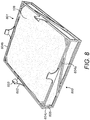
- the structure is supported by a set of bracing struts 604a that extend between struts 604b and across side faces of the retainer 600 and a rear face 800.
- An opposed contact face 801 of retainer 600 is generally open and is not obstructed by support struts 604a. Accordingly, with pad 107 located within cavity 605, the majority and in particular at least 80 or 90%, of the planar pad front face 108 is exposed for contact against the underside surface 502 of adaptor plate 500.
- Retainer 600 is releasably mountable at adaptor plate 500 via a set of attachment clips that project from retainer contact face 801.
- retainer 600 and in particular lengthwise and widthwise extending struts 604b comprises fingers 602 that project outward from and perpendicular to front face 108.
- Each finger 602 comprises a barb 603 directed inwardly towards pad front face 108.
- the length of each finger 602 is greater than a thickness of adaptor plate 500 so as to allow barbs 603 to be resiliently biased against and to hook over the raised adaptor plate edges 504 at plate face 501. Accordingly, with pad 107 housed within the cage-like retainer 600, pad 107 may be releasably clipped into contact with the bracket 100 via the mating of the retainer 600 onto adaptor plate 500 that is in turn secured to foot 101.
- the configuration of figures 5 to 7 is advantageous to provide thermal isolation of bracket 100 and composite board 203 via the intermediate positioned adaptor plate 500 and pad 107.
- Adaptor plate 500 also assists with the thermal isolation of bracket 100 and board 203 by providing an additional body of relatively low thermal conductivity between bracket 100 and board 203.
- the configuration of adaptor plate 500 and retainer 600 and in particular the cage-like structure of retainer 600 is advantageous to impart sufficient structural strength to the insulation layer 107 and to avoid loading induced deflection of the insulation layer assembly when mounted in position within a rainscreen system of figures 2 to 3 . That is, the retainer 600 and the adaptor plate 500 when coupled together are capable of transmitting load from the bracket 100 to the board 203 via attachment bolts 200. Accordingly, the subject invention is advantageous to provide both the desired structural attachment strength whilst achieving the desired thermal isolation of the various components of the rainscreen system of figures 2 to 3 .
- Example materials of the thermal isolating pad 107 are detailed below. The following examples are not limiting and the subject invention includes other alternative specific implementations having constituent materials that differ from those indicated. The relative concentrations of the constituent materials may also be selected to suit specific applications.
- Pad 107 comprises a material composition comprising components having thermal insulation characteristics including in particular silica particulate based materials.
- the material of pad 107 comprises at least one fibrous component.
- pad 107 comprises a foil cover provided at one or both faces.
- Table 1 - composition of pad 107 comprising CryogelTM Z available from Aspen Aerogels, Inc., MA 01532, USA. Chemical name CAS No.
- Bracket 100 comprising pad 107 according to the subject invention is advantageous to provide thermal performance enhancement over existing bracketry arrangements.
- the thermally isolating characteristic of the subject bracket 100 is achieved, in part, as the contact surface area of pad rear face 109 is at least equal to or greater than rear face 104 of foot 101 such that no part of foot 101 is capable of contacting the support substrate onto which bracket 100 is mechanically attached.
- pad 107 is capable of compression in use as bracket 100 is secured to the support substrate (board 203) via attachment bolts 200 without any reduction in the thermal conductivity resistance of pad 107.
- the present pad 107 is further advantageous to provide the desired structural performance and in particular to withstand shear and torsional forces transmitted through bracket 100 when bracket 100 is installed within an external cladding system according to figures 2 and 3 . That is, bracket 100 due to the choice of material of pad 107 is not configured to deflect appreciably in a vertical plane due to shear loading and also not to twist about its longitudinal axis due to torsional forces. Bracket 100 achieves the desired minimal deflection during use as it comprises a single pad only mounted at one end of the bracket. In one implementation, the pad comprises a density in a range 0.16 g/cm 3 to 0.2 g/cm 3 .
- pad 107 comprises at least one fire retardant component.
- pad 107 further comprises a material composition comprising silica particulate based components having thermal insulation characteristics and at least one fibrous component including for example fibrous glass.
- the fire retardant may comprise a metal oxide, a metal hydroxide, aluminium hydroxide, aluminium oxide, aluminium oxide hydroxide, or compounds including aluminium, phosphorous, nitrogen, antimony, chlorine, bromine, magnesium or zinc.
- the fire retardant comprises a clay within a polymer matrix including at least one organomodified clay.
- the clay comprises a montmorillonite.
- the fire retardant component comprises an inorganic compound such as antimony (III) oxide (Sb 2 O 3 ).
- Table 2 Composition of pad 107 comprising PyrogelTM XT-E available from Aspen Aerogels, Inc., MA 01532, USA. Chemical name CAS No. Concentration wt % Synthetic Amorphous Silica 7631-86-9 30-40% Methylsilylated Silica 68909-20-6 10-20% Fibrous Glass (textile grade) Not Applicable 40-50% Iron Oxide (iron (III) oxide) 1309-37-1 1-10% Aluminium Trihydrate (aluminium hydroxide) 21645-51-2 1-5% Optional additional components - Balance
- pad 107 is configured to withstand high temperature environment typically associated with a fire.
- the fire retardant is included at a concentration of 1 to 20% by weight.
- the flame retardant is configured to provide a pad 107 that does not disintegrate or decompose when exposed to temperatures of up to 650 °C.
- bracket 100 is configured to exhibit no or only minor deflection under loading (as would typically be encountered when bracket 100 is mounted within the cladding systems of figures 2 and 3 ) during and following exposure to fire.
- bracket 100 to satisfy further international standards such as EN 13501 (BR 135) - Fire Performance of External Thermal Insulation for Walls of Multistorey Buildings.
- bracket 100 comprising a material of example 2 (PyrogelTM) is capable of satisfying the (BR 135) BS 8414 and EN 1364-1/2 test criteria.
- pad 107 does not comprise a foil cover provided at one or both faces.
- Example 3 is a variation of example 2 in which pad 107 comprises at least one fire retardant component in addition to comprising silica particulate based components having thermal insulation characteristics and at least one fibrous component including for example fibrous glass.
- the fire retardant may comprise a silicate, belite, calcium monosilicate, calcium hydrosilicate, calcium metasilicate, calcium orthosilicate, grammite, or Ca 2 SiO 4 .
- Table 3 - Composition of pad 107 comprising SpaceloftTM A2 available from Aspen Aerogels, Inc., MA 01532, USA. Chemical name CAS No. Concentration wt % Synthetic Amorphous Silica 7631-86-9 30-40% Methylsilylated Silica 68909-20-6 5-15% Fibrous Glass (textile grade) Not Applicable 35-45% Calcium Silicate 13983-17-0 15-20%
- pad 107 is configured to withstand high temperature environment typically associated with a fire.
- the fire retardant is included at a concentration of 1 to 30% by weight.
- the flame retardant is configured to provide a pad 107 that does not disintegrate or decompose when exposed to temperatures of up to 650 °C.
- bracket 100 is configured to exhibit no or only minor deflection under loading (as would typically be encountered when bracket 100 is mounted within the cladding systems of figures 2 and 3 ) during and following exposure to fire.
- bracket 100 to satisfy further international standards such as EN 13501 (BR 135) - Fire Performance of External Thermal Insulation for Walls of Multistorey Buildings.
- bracket 100 comprising a material of example 3 (SpaceloftTM) is capable of satisfying the (BR 135) BS 8414, and EN 1364-1/2 test criteria as an A2 rating and ASTM E 84 fire test as a Class A rating.
- pad 107 does not comprise a foil cover provided at one or both faces.
- the present fire retardant pad 107 according to examples 2 and 3 is advantageous to withstand shear and torsional forces transmitted through bracket 100 (when mounted within an external cladding system according to figures 2 and 3 ) and not to deflect appreciably in a vertical plane due to shear loading and also not to twist about its longitudinal axis due to torsional forces during and after exposure fire at high temperatures of up to 650 °C.
- Such a configuration is achieved as the pad 107 does not disintegrate and maintains substantially its pre-fire physical and mechanical characteristics and composition.
Landscapes
- Engineering & Computer Science (AREA)
- Architecture (AREA)
- Civil Engineering (AREA)
- Structural Engineering (AREA)
- Physics & Mathematics (AREA)
- Electromagnetism (AREA)
- Acoustics & Sound (AREA)
- Building Environments (AREA)
Description
- The present invention relates to a bracket and cladding apparatus to support cladding panels at an external region of a building and in particular, although not exclusively, to a bracket and cladding assembly configured to provide an enhanced thermal barrier between the external cladding and inner components of the assembly positioned closest to the building.
- A common approach to thermally insulate buildings is to apply a ventilated rainscreen cladding system at the external region of the building. Typically, individual rainscreen panels are supported on a framework that is attached to the building external wall structure in which the framework is formed from brackets and rails to create an air space between the external cladding layer and inner leaf components of the framework system (typically boards). Commonly, the cavity between the external cladding and the inner leaf components is ventilated to the outside air to prevent entrapment of water and avoid humidity and condensation problems. Where it is required to thermally insulate the building, it is common to include one or more layers of insulation material behind the cladding panels. Accordingly, the external surface structure of the building is concealed from the sun, wind and rain to significantly reduce temperature variations at the external structure and accordingly provide a more controlled external environment of the building that is advantageous for the thermal efficiency management of the building interior.
- A variety of different rainscreen panel systems have been proposed in which the external cladding layer is separated from the building external wall structure via sub-frame assemblies, intermediate carrier boards and mounting brackets. Such arrangements are commonly referred to as steel framing systems (SFS). Example disclosures can be found in
CA 2820970 ;WO 2014/204590 andUS 2014/0311064 . - Document
DE 10 2012 016 025 A1 discloses a bracket to form part of an external building cladding assembly, the bracket comprising: - a foot having a contact face attachable to a structural element forming part of the cladding assembly or a building;
- - an attachment element to attach the bracket to an external cladding panel, an intermediate rail or a mount flange securable to the cladding panel;
- - an insulation layer; and
- - a retainer having an open structure to at least partially surround and house the insulation layer.
- However, existing systems are not optimised with regard to the thermal insulation between the external cladding layer and the external face of the building. In particular, regions of the steel sub-frame and mounting brackets typically provide an effective thermal bridge between the cladding and the external wall that reduces the effectiveness of any intermediate insulation material and the air gap between the cladding layer and the inner leaf boards. Additionally, conventional arrangements are susceptible to fire damage that may undermine significantly the structural integrity of the cladding assembly and compromise secure attachment at the external region of the building. Accordingly, what is required an external cladding arrangement that addresses the above problems.
- It is an objective of the present invention to provide a rainscreen cladding apparatus configured to enhance the thermal isolation of inner leaf components of an external wall cladding structure for a building from the external environment. It is a further specific objective to provide a mounting assembly having protective external rainscreen cladding panels that reduces the magnitude by which the mounting frame assembly transfers heat between the external cladding layers and the building external wall structure including in particular inner leaf components including for example cover boards, plaster boards, timber beams and the like.
- It is a further specific objective to provide a bracket for a rainscreen cladding apparatus that is resistant to degradation on exposure to fire so as to maintain structural integrity of the support within the cladding apparatus. It is a specific objective to provide a bracket to reduce the risk of the cladding apparatus moving appreciably or component parts becoming detached or lose at the external region of the building. It is a further specific objective to provide a bracket component for a rainscreen cladding system that is capable of satisfying fire performance standards relating to external wall structures of buildings including in particular BR 135 and in particular tests BS 8414.
- The objectives are achieved by providing a bracket forming part of an external panel based cladding system that reduces the thermal conduction through the bracket and between the cladding layer and the building wall structure. In particular the objectives are achieved via configuring the bracket with an insulation layer attached to a contact face of a foot part of the bracket in which the insulation layer comprises a conductivity of less than 0.09 W/(m·K) at 10°C. The present bracket is suitable to support outermost components of the external cladding system including in particular external cladding panels to form part of a cladding structure. The present brackets are suitable to form a mounting sub-frame attachable to the external wall structure that may be formed from cover boards typically formed from Gypsum or other suitable materials. Additionally, the present bracket is specifically adapted to form part of a steel framing system (SFS). In particular, the present bracket is suitable for attachment to intermediate carrier boards that are in turn mounted at the external wall structure via a sub-frame assembly.
- According to a first aspect of the present invention there is provided a bracket to form part of an external building cladding assembly, the bracket comprising: a foot having a contact face to be positioned to face internally towards the building and attachable to a structural element forming part of the cladding assembly or the building; an attachment element to attach the bracket to an external cladding panel, an intermediate rail or a mount flange securable to the cladding panel; an insulation layer attached to the contact face of the foot to sit intermediate the foot and the structural element; wherein a thermal conductivity of the layer is less than 0.09 W/(m·K) at 10 °C.
- Preferably, the attachment element comprises a neck extending perpendicular or transverse from the foot, the neck attachable to an external cladding panel, an intermediate rail or a mount flange securable to the cladding panel. Optionally, the attachment element comprises a flange, connector, aperture, bolts, screws and/or fitting configured to be engaged and to lock with a cooperating element provided at the cladding panel, intermediate rail or mount flange to connect the bracket to such structures as part of a rainscreen assembly at the building external wall.
- The thermal conductivities of the layer material as described herein are stated at room temperature or a temperature in the range 20 to 27°C, 23 to 27 °C and in particular 24 to 26°C and are stated where the insulation material is provided at a compressive load of 13.79 kPa (2psi).
- Optionally, the thermal conductivity of the insulation layer is less than 0.05, 0.04 or 0.03 W/(m·K) at 10 °C. Optionally, the thermal conductivity of the insulation layer is in the range 0.002 to 0.06 W/(m·K) at 10 °C. Optionally, the thermal conductivity of the insulation layer is in the range 0.005 to 0.04; 0.005 to 0.03; 0.01 to 0.03; 0.01 to 0.028 or 0.01 to 0.026 W/(m·K) at 10 °C. Preferably, the insulation layer comprises a silica aerogel material optionally comprising a fibre coating at a first and/or second surface of the silica aerogel. Optionally, the insulation may be provided at the bracket as a coating resultant from a coating process. Optionally the insulation coating is configured to be self-bonding to the contact face of the foot of the bracket without the need for additional bonding agents or mechanical attachments. Optionally, insulation layer is attached to the contact face of the foot of the bracket via an adhesive or mechanical attachments.
- Optionally, the bracket further comprises a detachable mounting base positionable at the contact face of the foot having a generally planar configuration. Preferably, the mounting base comprises at least one slot to receive an attachment bolt or the like. Optionally, the mounting base comprises shoulders projecting upwardly from a mount face, the shoulders positioned at the corners of the mount face. Optionally, a thickness of the mounting base including the shoulders is less than a thickness the insulation layer such that no part of the shoulders is configured to contact the support substrate to which the insulation layer is attached.
- Optionally, the insulation layer is formed as a pad and comprises a thermal conductivity that is less than 0.05 W/(m·K) at 10 °C. Optionally, the insulation layer comprises a silica aerogel and a fibre based insulation material having a conductivity in the range 0.01 to 0.05 W/(m·K) at 10 °C. Optionally, the insulation layer comprises: synthetic amorphous silica; methylsilytated silica; polyethylene tetraphthalate or polyester; fibrous glass.
- Optionally, the insulation layer comprises at least one fire retardant component. Optionally, the fire retardant comprises any one or combination of the set of aluminium hydroxide, aluminium oxide hydroxide, antimony (III) oxide, a clay, a clay within a polymer matrix, an organomodified clay, montmorillonite or compounds or materials including aluminium, phosphorous, nitrogen, antimony, chloride, bromine, magnesium, zinc, a silicate, or calcium silicate.
- Optionally, the flame retardant comprises iron oxide and/or aluminium trihydrate (aluminium hydroxide Al(OH)3).
- Optionally, the insulation layer comprises: silica; a fibrous component preferably fibrous glass; and a flame retardant component. Optionally, the silica is included at 25 to 65% by weight; the fibrous material is included at 35 to 55% by weight and the flame retardant component is included at 1 to 20% by weight.
- Optionally, the bracket comprises synthetic amorphous silica at 25 to 45% by weight; methylsilated silica at 1 to 25% by weight; fibrous glass at 35 to 55% by weight; iron oxide at 0.5 to 15% by weight; and aluminium trihydrate at 0.5 to 10% by weight.
- Optionally, the flame retardant component comprises calcium silicate. Optionally, the bracket comprises: synthetic amorphous silica at 25 to 45% by weight; methylsilated silica at 1 to 25% by weight; fibrous glass at 30 to 50% by weight; calcium silicate at 10 to 25% by weight.
- Optionally, the bracket comprises a single insulation layer permanently attached to the foot. Optionally, the insulation layer comprises a thickness in a plane substantially perpendicular to the foot of between 3 to 15 mm, 5 to 10 mm. Such a thickness is optimised to provide sufficient thermal isolation between the bracket and an underlying structure on which the bracket is mounted whilst also maintaining the capability of the bracket to withstand the loading forces transmitted through the cladding assembly due for example to wind shear and the weight of the various components of the assembly. Optionally, the bracket may comprise strengthening flanges projecting rearwardly from a rear face of the foot to enhance the strength characteristics of the bracket to withstand loading forces. Optionally, the brackets may comprise ribs projecting from a rear face of the foot with the ribs extending at least partially through the insulation layer that enhance the strength characteristics. Optionally, the flanges or ribs comprise the same or a different material to the bracket and/or insulation material.
- Optionally, the bracket further comprises an adhesive provided between the layer and the foot such that the layer is non-detachably mounted at the foot. The adhesive may be a thermal bonding agent, an epoxy or other bonding resin.
- Optionally, the bracket and in particular the foot and the neck comprise an aluminium or an aluminium based material.
- Optionally, the bracket may comprise an adaptor plate positioned intermediate the contact face of the foot and the insulation layer. Optionally, the adaptor plate may be formed as a plate or block component releasably mountable to the foot of the bracket. The adaptor plate may be attached via the same attachment bolts used to attach the bracket to a substrate board or separate attachments may be provided including bolts, screws, pins, lugs, clips and the like. Optionally, the adaptor plate comprises a thermoplastic material such as polypropylene. Optionally, a thickness of the adaptor plate is greater than a thickness of the foot. Optionally, the adaptor plate may comprise a lip extending along a perimeter of the adaptor plate to sit over and about a perimeter of the foot such that the adaptor plate is configured to overlap onto the foot. Preferably, the adaptor plate is configured such that no part of the foot is positioned in direct contact against the substrate board. The adaptor plate is advantageous to provide structural strength to the bracket by enlarging the footprint and also assist with the thermal isolation between the bracket and the underlying substrate board.
- According to the invention, the bracket further comprises a retainer having an open structure to at least partially surround and house the insulation layer, the retainer being releasably attached to the foot. Preferably, the retainer is formed from elongate thin webbing so as to define a cage-like structure. The thickness of the cage material is maintained to a minimum to reduce as far as possible any thermal bridging via the retainer when mounted in position between the bracket and substrate board. Optionally, the retainer is formed as a mesh, gauze, ribbed, webbed or strap-like structure.
- Preferably, the retainer comprises attachments to releasably attach to the foot or adaptor plate to releasably mount the insulation layer in contact with the foot or the adaptor plate. The attachments may comprise any form of hooks, clips, pins, screws, bolts, adhesive or the like. Preferably, the attachments comprise a plurality of barbed fingers projecting from lengthwise and/or widthwise extending perimeter edges of the retainer.
- According to a second aspect of the present invention there is provided a building cladding assembly to form an external wall region of a building comprising: a plurality of cladding panels positionable in an edge-to-edge arrangement to form an external cladding layer of a building; a plurality of brackets as claimed herein, each attachment element of each bracket attachable to one of the cladding panels, an intermediate rail or mount flange securable to the cladding panels, the foot securable to a structural element forming part of the cladding assembly or the building via the respective insulation layers.
- Optionally, the assembly further comprises cladding rails attachable to the necks of the brackets to form a rail support structure on which to mount the cladding panels. The cladding rails may comprise a head and a tail, with the head extending generally parallel to the external cladding boards and the tail extending generally parallel to the neck of the bracket.
- Preferably, the assembly further comprises a plurality of cover boards positionable against timber beams that form a part of an external region of the building, the feet of the brackets attachable to the cover boards via the respective insulation layers. Optionally, the cover boards may comprise acoustic plaster boards and the assembly may comprise a single layer or a plurality of layers of cover boards at the external wall of the building.
- Optionally, the assembly may comprise a steel frame sub-assembly (SFS) arrangement comprising a sub-frame mountable to a plurality of cover boards positioned to form a part of an external region of the building; a plurality of carrier boards mountable to the sub-frame to provide a sub-cladding layer separated from the cover boards via the sub-frame; and wherein the brackets are mountable to the carrier boards via the respective insulation layers to spatially separate the external cladding layer from the sub-cladding layer.
- Optionally, the assembly may comprise a first insulation material positionable between the external cladding layer and the carrier boards. Optionally, the assembly may further comprise a second insulation material positionable between the carrier boards and the cover boards. The insulation material may comprise a fibrous based or mineral based sheet positioned in a gap region between the external cladding panels and the building cover board and/or the region between a carrier board and the building external surface where the system is an SFS cladding assembly.
- A specific implementation of the present invention will now be described, by way of example only, and with reference to the accompanying
figures 6-8 .Figures 1-5 provide further background information helpful for the understanding of the present invention. -
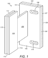
Figure 1 is an external perspective view of a bracket forming part of a building cladding assembly to form an external wall region of a building having a low thermal conductivity material attached to the bracket to reduce thermal conductivity through the cladding assembly; -
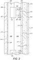
Figure 2 illustrates the bracket offigure 1 forming a component part within a building cladding assembly representing an external wall region of a building; -
Figure 3 illustrates the bracket offigure 1 forming part of a building cladding assembly that includes a sub-frame with the brackets mounted on carrier boards positioned intermediate the sub-frame and external cladding panels; -
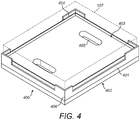
Figure 4 illustrates an adaptor component attachable to a foot part of the bracket to mount a low thermal conductivity layer at the bracket; -
Figure 5 is a perspective view of the bracket offigures 1 to 3 having an adaptor component configured for mounting at a foot of the bracket; -
Figure 6 is a perspective view of the bracket and adaptor offigure 5 attachable to a retainer at least partially housing an insulation layer; -
Figure 7 is an underside perspective view of the retainer and insulation layer offigure 6 ; -
Figure 8 an upper perspective view of the retainer and insulation layer offigure 7 . - Referring to
figure 1 abracket 100 to form part of a building cladding assembly for cladding an external wall region of a building comprises generally afoot 101, aneck 102 extending generally perpendicular fromfoot 101 and ahead 103 provided at an opposite end ofneck 102 relative to foot 101.Foot 101 comprises a generally planar body having afront face 105 and arear face 104. A pair ofelongate slots 106 extend throughfoot 101 betweenfaces bracket 100 in position within the cladding assembly.Neck 102 projects fromfront face 105 toseparate head 103 fromfoot 101. According to the specific implementation,foot 101,neck 102 andhead 103 are formed integrally from aluminium so as to provide a generally rigid structure.Head 103 comprises a pair ofopposed plates 111 that are spatially separated from one another to provide a mouth orgap region 110. One or bothplates 111 are hingeably mounted together atrearward edge 112 such thatplates 111 may be resiliently separated atedge 113 to increase the size ofmouth 110 when mounting a flange or tail part of a rail system that in turn supports external cladding panels. - According to further specific implementations,
head 103 may be formed from a single piece or component and comprise apertures to receive mounting bolts, pins, screws etc to securebracket 100 to a rail or flange supporting the cladding panels.Other head 103 mechanisms may also be envisaged such as bayonet attachments, tongue and groove arrangements, click-lock attachments, push fit connections etc. -
Bracket 100 further comprises athermal insulation layer 107 non-detachably mounted at footrear face 104. According to the specific implementation, the lowthermal conductivity pad 107 is attached torear face 104 via an adhesive such as an epoxy resin.Pad 107 also comprises a pair ofelongate slots 114 being dimensioned and positioned to align respectively with the slots 106 (extending through foot 101) to receive attachment bolts. According to the specific implementation,pad 107 comprises a material having a thermal conductivity of 0.010 to 0.030 W/(m·K) at a mean temperature of 23 to 26 °C and as measured as a compressive load of 13.79 kPa. In one implementation,pad 107 comprises Cryogel™ available from Aspen Aerogels, Inc., NA 05132, USA.Pad 107 comprises a thickness in a plane perpendicular to face 104 of 5 mm to 10 mm and incorporates the silica aerogel material and a flexible fibre coating provided at afront face 108 and/or arear face 109 ofpad 107. An epoxy or thermal bonding agent is provided to permanently attachpad 107 viafront face 108 to therear face 104 offoot 101. - Referring to
figure 2 ,bracket 100 is suitable for inclusion within an external rainscreen cladding system that is configured as an external wall structure of a building. The building interior is defined by anacoustic plaster board 215 that represents an inner leaf of the system having arear face 217 that is internal facing within the building. Timber studs (beams) 204 are, in turn, mounted to an externalfacing mount face 216 ofplaster board 215. Acomposite board 203 is secured to afront face 212 oftimber studs 204 via arear face 213. Accordingly,composite board 203,studs 204 andplaster board 215 represent inner leaf components of the external wall structure that may be regarded as an external wall of the building. A plurality of thebrackets 100 are secured directly to amount face 211 of composite boards 203 (alternatively termed cover boards) via mating contact with padrear face 109. Eachbracket 100 is secured to eachcover board 203 viaattachment bolts 200 that extend throughfoot 101 having bolt heads 201 positioned againstfront face 105. Accordingly,foot 101 is thermally isolated fromcover board 203 viapad 107. Eachbracket head 103 is secured to atail member 206 that forms a rearward part of a panel mountingrail assembly 205. In particular,tail member 206 is formed as an elongate plate at least partially received withinmouth 110 betweenbracket plates 111 so as to be gripped by frictional contact to securely mountrail 205 atbrackets 100. Accordingly,tail member 206 is aligned generally parallel withbracket plates 111 andneck 102 and generally perpendicular tofoot 101,insulation pad 107 andcover board 203. Arail head 207 also extends perpendicular totail member 206.Rail head 207 comprises amount face 214 for positioning in contact and attachment to arear face 209 of a plurality ofcladding panels 208. Eachpanel 208 comprises anexternal face 210 that represents an external-most part of the cladding assembly. Due to the respective lengths ofbracket neck 102,head 103 andtail member 206, aspatial gap 202 is created betweencover board 203 andcladding panels 208. According to a further embodiment, a sheet insulation material may be positioned in thegap region 202 between coverboard mount face 211 and external cladding panelrear face 209 to enhance the thermal partitioning ofexternal cladding panels 208 andboards -
Bracket insulation pad 107 is effective to minimise the thermal conductivity from theexternal cladding panels 208 to thecover board 203 at the region immediately behindfoot 101. That is, the region of footrear face 104 would otherwise provide a thermal bridge to betweenpanels 208 and coverboards 203. By utilisingpad 107 of a low thermal conductivity material,bracket 100 thermally isolates the innerleaf plaster board 215. To further enhance thermal isolation, suitable low thermal conductivity washers or flanges may be provided under bolt heads 201 to thermally isolatebolts metallic foot 101. -
Figure 3 illustrates part of a steel framing system (SFS) cladding assembly. The building external wall is, in part, defined by a sub-frame assembly that comprises aninnermost plaster board 215 as described with reference tofigure 2 representing an innermost component of the assembly. According to the arrangements offigures 2 and3 , a plurality ofboards 215 may be provided as the innermost components of the assembly to provide acoustic insulation in addition to enhanced thermal insulation. The sub-frame assembly comprises a plurality of lightweight steelframe support members 300 attached directly to mountface 216 ofplaster board 215. Cover boards 203 (alternatively termed a carrier boards) are mounted at an opposite side of thesupport members 300 via carrier boardrear face 213. Accordingly, aspatial gap 304 is created between carrier boardsrear face 213 and plaster boards mountface 216. A plurality ofbrackets 100 are then attached to afront face 211 ofcarrier boards 203 via contact betweenrear face 109 ofinsulation pad 107 and carrierboard front face 211 as detailed with reference tofigure 2 . Accordingly,carrier boards 203 are positionedintermediate brackets 100 and steelframe support members 300. The external-most layer ofcladding panels 208 are mounted at thebrackets 100 via therail assembly 205 as described with reference tofigure 2 . Also, according to the further specific implementation,brackets 100 are secured tocarrier board 203 via thesame bolts figure 2 . According to further embodiments,bolts carrier boards 203 and into respective steelframe support members 300. As will be appreciated,frame support members 300 may be attached tocarrier boards 203 via respective attachment bolts, screws, pins etc. As with the embodiments offigure 2 , should it be required to enhance the thermal isolation betweencladding panels 208 andplaster board 215, a first layer of insulation material (not shown) may be positioned withingap region 202 and layered ontofront face 211 ofcarrier boards 203. Additionally, a second layer of insulation material (not shown) may be positioned withingap region 304 in contact between carrier boardrear face 213 and/or coverboard mount face 216. - According to the embodiments of
figures 1 to 3 , thepresent bracket assembly 100 is advantageous via the low thermal conductivity ofpad 107 to provide a rainscreen cladding assembly of reduced total thickness betweeninner leaf board 215 andcladding panels 208. - In one implementation and referring to
figure 4 pad 107 may be attached tobracket 100 via an intermediate adaptor indicated generally byreference 400.Adaptor 400 comprises a generallyplanar base 401 having anunderside surface 402 and asupport surface 403.Underside surface 402 is configured for positioning against and in contact withrear face 104 offoot 101 and comprisesslots 405 positioned and dimensioned to correspond toslots 106 to receive attachment bolts so as to anchorbracket 100 to a suitable support substrate (i.e., boards 203).Base 401 comprises fourshoulders 404 positioned at eachcorner 406 ofbase 401 that project upwardly a relatively short height/distance fromsupport surface 403. - Each
shoulder 404 is formed as a relatively thin border section projecting from eachcorner 406 and extending a short lengthwise and widthwise distance along a part of the perimeter edge that definessupport surface 403. A thickness of eachshoulder 401 in the plane ofsupport surface 403 is significantly less than a thickness ofbase 401 in a plane perpendicular to the plane ofsupport surface 403. Accordingly, should any one of theshoulders 404 contact the substrate to whichpad 107 is attached (for example under extreme compression) any thermal bridging effect throughshoulders 404 is minimised and may be regarded as negligible.Shoulders 404 are configured to facilitate mounting ofpad 107 onsupport surface 403 and are not intended to provide structural support and in particular to enhance the surface area contact between the bracket and thesubstrate board 203. The present bracket is constructed such that the padrear face 109 provides exclusively the contact of thebracket 100 onto thesupport substrate 203 so as to maximise the thermal isolation function of thepresent bracket 100.Base 401 and inparticular support surface 403 is configured to support pad 107 (illustrated with dashed lines) withpad 107 having a footprint or surface area corresponding to that ofsupport surface 403 and therear face 104 ofbracket 100. The height of eachshoulder 404 is appreciably less than a thickness of pad 107 (in the plane perpendicular to the plane of support surface 403) such that even under compression,pad 107 provides the exclusive contact and intermediate coupling between thesupport substrate 203 and thefoot 101. That is under normal loading conditions, no part of eachshoulder 404 is capable of contacting the support substrate. - A specific implementation of the bracket and adaptor of
figures 1 to 4 is detailed according tofigures 5 to 8 . According to the further implementation,bracket 100 comprises the same features as described with reference tofigure 1 including for example but not limited to thefoot 101,neck 102,head 103 and associated components and features. According to the specific implementation, anadaptor plate 500 is formed from a polypropylene thermoplastic and comprises asupport surface 501 for positioning in contact against therear face 104 offoot 101.Adaptor plate 500 also comprises anopposed underside surface 502 for positioning againstinsulation layer 107. As described with reference tofigure 4 , a plurality ofelongate slots 503 are formed throughplate 500 between the opposed faces 501, 502.Plate 500 also comprises a raisededge 504 in the form of a lip or step extending around a perimeter ofplate 500 along the lengthwise and widthwise extending perimeter edges.Plate 500 andedges 504 are dimensioned to sit over and aboutfoot 101 such thatfoot 101 is at least partially housed within the recess defined by the upstanding adaptor plate edges 504.Elongate slots 503 are dimensioned so as to be co-aligned withslots 114 extending throughfoot 101 such thatplate 500 is capable of being releasably mountable atfoot 101 via theattachment bolts 200. - Referring to
figures 6 to 8 ,bracket 100 also comprises a retainer indicated generally byreference 600.Retainer 600 comprises an open or cage-like structure to at least partially housepad 107 within an internal region indicated generally byreference 605.Region 605 is defined by a plurality of interconnect elongate struts that collectively define a containing frame having the cage-like structure. In particular, a set of lengthwise and widthwise extendingstruts 604b define a perimeter footprint of theretainer 600 with the lengthwise and widthwisestruts 604b connected via corner struts 604c that together define a cuboidal open cage structure defininginternal cavity region 605. The structure is supported by a set of bracing struts 604a that extend betweenstruts 604b and across side faces of theretainer 600 and arear face 800. Anopposed contact face 801 ofretainer 600 is generally open and is not obstructed bysupport struts 604a. Accordingly, withpad 107 located withincavity 605, the majority and in particular at least 80 or 90%, of the planarpad front face 108 is exposed for contact against theunderside surface 502 ofadaptor plate 500. Accordingly, whenretainer 600 is mounted in position and in contact againstadaptor plate 500, the undersiderear face 109 ofpad 107 is largely exposed for contact against thecover board 203 whenbracket 100 is mounted in position within the external rainscreen cladding system as described referring tofigures 2 and3 . -
Retainer 600 is releasably mountable atadaptor plate 500 via a set of attachment clips that project fromretainer contact face 801. In particular,retainer 600 and in particular lengthwise and widthwise extendingstruts 604b comprisesfingers 602 that project outward from and perpendicular tofront face 108. Eachfinger 602 comprises abarb 603 directed inwardly towardspad front face 108. The length of eachfinger 602 is greater than a thickness ofadaptor plate 500 so as to allowbarbs 603 to be resiliently biased against and to hook over the raised adaptor plate edges 504 atplate face 501. Accordingly, withpad 107 housed within the cage-like retainer 600,pad 107 may be releasably clipped into contact with thebracket 100 via the mating of theretainer 600 ontoadaptor plate 500 that is in turn secured to foot 101. - The configuration of
figures 5 to 7 is advantageous to provide thermal isolation ofbracket 100 andcomposite board 203 via the intermediate positionedadaptor plate 500 andpad 107.Adaptor plate 500 also assists with the thermal isolation ofbracket 100 andboard 203 by providing an additional body of relatively low thermal conductivity betweenbracket 100 andboard 203. The configuration ofadaptor plate 500 andretainer 600 and in particular the cage-like structure ofretainer 600 is advantageous to impart sufficient structural strength to theinsulation layer 107 and to avoid loading induced deflection of the insulation layer assembly when mounted in position within a rainscreen system offigures 2 to 3 . That is, theretainer 600 and theadaptor plate 500 when coupled together are capable of transmitting load from thebracket 100 to theboard 203 viaattachment bolts 200. Accordingly, the subject invention is advantageous to provide both the desired structural attachment strength whilst achieving the desired thermal isolation of the various components of the rainscreen system offigures 2 to 3 . - Example materials of the thermal isolating
pad 107 are detailed below. The following examples are not limiting and the subject invention includes other alternative specific implementations having constituent materials that differ from those indicated. The relative concentrations of the constituent materials may also be selected to suit specific applications. -
Pad 107 comprises a material composition comprising components having thermal insulation characteristics including in particular silica particulate based materials. Preferably, the material ofpad 107 comprises at least one fibrous component. According to the example 1,pad 107 comprises a foil cover provided at one or both faces. The constituents of the material ofpad 107 according to example 1 are detailed in table 1.Table 1 - composition of pad 107 comprising Cryogel™ Z available from Aspen Aerogels, Inc., MA 01532, USA.Chemical name CAS No. Concentration wt % Synthetic Amorphous Silica 7631-86-9 25-40% Methylsilylated Silica 68909-20-6 10-20% Polyethylene terephthalate (PET or polyester) 25038-59-9 10-20% Fibrous Glass (textile grade) - 10-20% Magnesium Hydroxide 1309-42-8 0-5% Aluminium Foil 7429-90-5 0-5% -
Bracket 100 comprisingpad 107 according to the subject invention is advantageous to provide thermal performance enhancement over existing bracketry arrangements. The thermally isolating characteristic of thesubject bracket 100 is achieved, in part, as the contact surface area of padrear face 109 is at least equal to or greater thanrear face 104 offoot 101 such that no part offoot 101 is capable of contacting the support substrate onto whichbracket 100 is mechanically attached. Additionally, due to the aerogel and fibrous composite material,pad 107 is capable of compression in use asbracket 100 is secured to the support substrate (board 203) viaattachment bolts 200 without any reduction in the thermal conductivity resistance ofpad 107. - The
present pad 107 is further advantageous to provide the desired structural performance and in particular to withstand shear and torsional forces transmitted throughbracket 100 whenbracket 100 is installed within an external cladding system according tofigures 2 and3 . That is,bracket 100 due to the choice of material ofpad 107 is not configured to deflect appreciably in a vertical plane due to shear loading and also not to twist about its longitudinal axis due to torsional forces.Bracket 100 achieves the desired minimal deflection during use as it comprises a single pad only mounted at one end of the bracket. In one implementation, the pad comprises a density in a range 0.16 g/cm3 to 0.2 g/cm3. - In some specific implementations and under example 2,
pad 107 comprises at least one fire retardant component. According to example 2, pad 107 further comprises a material composition comprising silica particulate based components having thermal insulation characteristics and at least one fibrous component including for example fibrous glass. - Where the
pad 107 comprises a fire retardant composition, the fire retardant may comprise a metal oxide, a metal hydroxide, aluminium hydroxide, aluminium oxide, aluminium oxide hydroxide, or compounds including aluminium, phosphorous, nitrogen, antimony, chlorine, bromine, magnesium or zinc. Optionally, the fire retardant comprises a clay within a polymer matrix including at least one organomodified clay. Optionally, the clay comprises a montmorillonite. In some implementations, the fire retardant component comprises an inorganic compound such as antimony (III) oxide (Sb2O3). The constituents of the material ofpad 107 according to example 2 are detailed in table 2.Table 2 - Composition of pad 107 comprising Pyrogel™ XT-E available from Aspen Aerogels, Inc., MA 01532, USA.Chemical name CAS No. Concentration wt % Synthetic Amorphous Silica 7631-86-9 30-40% Methylsilylated Silica 68909-20-6 10-20% Fibrous Glass (textile grade) Not Applicable 40-50% Iron Oxide (iron (III) oxide) 1309-37-1 1-10% Aluminium Trihydrate (aluminium hydroxide) 21645-51-2 1-5% Optional additional components - Balance - In specific implementations,
pad 107 is configured to withstand high temperature environment typically associated with a fire. Preferably, the fire retardant is included at a concentration of 1 to 20% by weight. The flame retardant is configured to provide apad 107 that does not disintegrate or decompose when exposed to temperatures of up to 650 °C. Accordingly, in such implementations,bracket 100 is configured to exhibit no or only minor deflection under loading (as would typically be encountered whenbracket 100 is mounted within the cladding systems offigures 2 and3 ) during and following exposure to fire. Accordingly, the structural integrity of the external cladding systems offigures 2 and3 is maintained even in the event of a fire at the external claddingassembly enabling bracket 100 to satisfy further international standards such as EN 13501 (BR 135) - Fire Performance of External Thermal Insulation for Walls of Multistorey Buildings. In particular thepresent bracket 100 comprising a material of example 2 (Pyrogel™) is capable of satisfying the (BR 135) BS 8414 and EN 1364-1/2 test criteria. According to example 2,pad 107 does not comprise a foil cover provided at one or both faces. - Example 3 is a variation of example 2 in which
pad 107 comprises at least one fire retardant component in addition to comprising silica particulate based components having thermal insulation characteristics and at least one fibrous component including for example fibrous glass. - The fire retardant may comprise a silicate, belite, calcium monosilicate, calcium hydrosilicate, calcium metasilicate, calcium orthosilicate, grammite, or Ca2SiO4. The constituents of the material of
pad 107 according to example 3 are detailed in table 3.Table 3 - Composition of pad 107 comprising Spaceloft™ A2 available from Aspen Aerogels, Inc., MA 01532, USA.Chemical name CAS No. Concentration wt % Synthetic Amorphous Silica 7631-86-9 30-40% Methylsilylated Silica 68909-20-6 5-15% Fibrous Glass (textile grade) Not Applicable 35-45% Calcium Silicate 13983-17-0 15-20% - In specific implementations,
pad 107 is configured to withstand high temperature environment typically associated with a fire. Preferably, the fire retardant is included at a concentration of 1 to 30% by weight. The flame retardant is configured to provide apad 107 that does not disintegrate or decompose when exposed to temperatures of up to 650 °C. Accordingly, in such implementations,bracket 100 is configured to exhibit no or only minor deflection under loading (as would typically be encountered whenbracket 100 is mounted within the cladding systems offigures 2 and3 ) during and following exposure to fire. Accordingly, the structural integrity of the external cladding systems offigures 2 and3 is maintained even in the event of a fire at the external claddingassembly enabling bracket 100 to satisfy further international standards such as EN 13501 (BR 135) - Fire Performance of External Thermal Insulation for Walls of Multistorey Buildings. In particular thepresent bracket 100 comprising a material of example 3 (Spaceloft™) is capable of satisfying the (BR 135) BS 8414, and EN 1364-1/2 test criteria as an A2 rating and ASTM E 84 fire test as a Class A rating. According to example 3,pad 107 does not comprise a foil cover provided at one or both faces. - The present
fire retardant pad 107 according to examples 2 and 3 is advantageous to withstand shear and torsional forces transmitted through bracket 100 (when mounted within an external cladding system according tofigures 2 and3 ) and not to deflect appreciably in a vertical plane due to shear loading and also not to twist about its longitudinal axis due to torsional forces during and after exposure fire at high temperatures of up to 650 °C. Such a configuration is achieved as thepad 107 does not disintegrate and maintains substantially its pre-fire physical and mechanical characteristics and composition.
Claims (15)
- A bracket (100) to form part of an external building cladding assembly, the bracket (100) comprising:a foot (101) having a contact face (104) attachable to a structural element forming part of the cladding assembly or a building;an attachment element (103) to attach the bracket (100) to an external cladding panel (208), an intermediate rail (205) or a mount flange securable to the cladding panel (208);an insulation layer (107) attachable to the contact face (104) of the foot (101) to sit intermediate the foot (101) and the structural element, a thermal conductivity of the layer (107) being less than 0.09 W/(m·K) at 10 °C; anda retainer (600) having an open structure to at least partially surround and house the insulation layer (107), wherein the retainer is releasably attachable to the foot (101).
- The bracket (100) as claimed in claim 1 when the thermal conductivity is less than 0.05 W/(m·K) at 10 °C; less than 0.03 W/(m·K) at 10 °C; or wherein the thermal conductivity is in the range 0.01 to 0.03 W/(m·K) at 10 °C.
- The bracket (100) as claimed in any preceding claim wherein the insulation layer (107) comprises a fibre based insulation material; a silica aerogel and/or a fibrous component.
- The bracket (100) as claimed in any preceding claim wherein the insulation layer (107) comprises:• synthetic amorphous silica;• methylsilytated silica;• polyethylene tetraphthalate or polyester;• fibrous glass.
- The bracket (100) as claimed in any one of claims 1 to 3 wherein the insulation layer (107) comprises at least one fire retardant component.
- The bracket (100) as claimed in claim 5 wherein the fire retardant comprises any one or combination of the set of aluminium hydroxide, aluminium oxide hydroxide, antimony (III) oxide, a clay, a clay within a polymer matrix, an organo modified clay, montmorillonite or compounds or materials including aluminium, phosphorous, nitrogen, antimony, chloride, bromine, magnesium, zinc, a silicate, or calcium silicate.
- The bracket (100) as claimed in any one of claims 1 to 3 wherein the insulation layer (107) comprises:• silica;• a fibrous component;• a flame retardant component.
- The bracket (100) as claimed in claim 7 wherein the flame retardant comprises iron oxide and/or aluminium trihydrate (aluminium hydroxide Al(OH)3).
- The bracket (100) as claimed in 7 wherein the flame retardant component comprises calcium silicate.
- The bracket (100) as claimed in 9 comprising:• synthetic amorphous silica at 25 to 45% by weight;• methylsilated silica at 1 to 25% by weight;• fibrous glass at 30 to 50% by weight;• calcium silicate at 10 to 25% by weight.
- The bracket (100) as claimed in any preceding claim further comprising an adaptor plate (500) positioned intermediate the contact face (104) of the foot (101) and the insulation layer (107), the adaptor plate (500) comprising a thermoplastic material.
- The bracket (100) as claimed in any preceding claim wherein the retainer (600) comprises attachments (602) to releasably attach to the foot (101) or adaptor plate (500) to releasably mount the insulation layer (107) in contact with the foot (101) or the adaptor plate (500).
- The bracket (100) as claimed in claim 12 wherein the retainer (600) comprises a cage-like structure.
- A building cladding assembly to form an external wall region of a building comprising:a plurality of cladding panels (208) positionable in an edge-to-edge arrangement to form an external cladding layer of a building;a plurality of brackets (100) as claimed in any preceding claim, each attachment element (103) of each bracket (100) attachable to one of the cladding panels (208), an intermediate rail (205) or mount flange securable to the cladding panels (208), the foot (101) securable to a structural element forming part of the cladding assembly or the building via the respective insulation layers (107).
- The assembly as claimed in claim 14 further comprising:a plurality of inner leaf boards (215) positioned to form an inner leaf of the assembly;a sub-frame (300) mountable to a plurality of the inner leaf boards (215);a plurality of cover boards (203) mountable to the sub-frame (300) to provide a sub-cladding layer separated from the inner leaf boards (215) via the sub-frame (300); andwherein the brackets (100) are mountable to the cover boards (203) via the respective insulation layers (107) to spatially separate the external cladding layer from the sub-cladding layer.
Priority Applications (1)
| Application Number | Priority Date | Filing Date | Title |
|---|---|---|---|
| EP20157415.9A EP3670782A1 (en) | 2015-06-26 | 2016-06-24 | Rainscreen cladding apparatus |
Applications Claiming Priority (4)
| Application Number | Priority Date | Filing Date | Title |
|---|---|---|---|
| GBGB1511292.3A GB201511292D0 (en) | 2015-06-26 | 2015-06-26 | Rainscreen cladding apparatus |
| GBGB1600576.1A GB201600576D0 (en) | 2016-01-12 | 2016-01-12 | Rainscreen cladding apparatus |
| GBGB1607808.1A GB201607808D0 (en) | 2016-05-04 | 2016-05-04 | Rainscreen cladding apparatus |
| PCT/GB2016/051895 WO2016207648A1 (en) | 2015-06-26 | 2016-06-24 | Rainscreen cladding apparatus |
Related Child Applications (1)
| Application Number | Title | Priority Date | Filing Date |
|---|---|---|---|
| EP20157415.9A Division EP3670782A1 (en) | 2015-06-26 | 2016-06-24 | Rainscreen cladding apparatus |
Publications (2)
| Publication Number | Publication Date |
|---|---|
| EP3314069A1 EP3314069A1 (en) | 2018-05-02 |
| EP3314069B1 true EP3314069B1 (en) | 2020-02-19 |
Family
ID=56263989
Family Applications (2)
| Application Number | Title | Priority Date | Filing Date |
|---|---|---|---|
| EP20157415.9A Pending EP3670782A1 (en) | 2015-06-26 | 2016-06-24 | Rainscreen cladding apparatus |
| EP16732723.8A Active EP3314069B1 (en) | 2015-06-26 | 2016-06-24 | Rainscreen cladding apparatus |
Family Applications Before (1)
| Application Number | Title | Priority Date | Filing Date |
|---|---|---|---|
| EP20157415.9A Pending EP3670782A1 (en) | 2015-06-26 | 2016-06-24 | Rainscreen cladding apparatus |
Country Status (3)
| Country | Link |
|---|---|
| EP (2) | EP3670782A1 (en) |
| GB (2) | GB2541513B (en) |
| WO (1) | WO2016207648A1 (en) |
Families Citing this family (7)
| Publication number | Priority date | Publication date | Assignee | Title |
|---|---|---|---|---|
| LT6656B (en) * | 2017-12-08 | 2019-09-25 | UAB "Serfas" | Bracket for ventilated facade |
| EP3686370A1 (en) * | 2019-01-25 | 2020-07-29 | Pittsburgh Corning Europe NV | Façade cladding fixing system |
| EP3789559A1 (en) * | 2019-09-04 | 2021-03-10 | Benx Limited | Fire-resistant spacer body use in structural cladding |
| CN111217570A (en) * | 2020-01-15 | 2020-06-02 | 中国十七冶集团有限公司 | Preparation method of external wall heat insulation system with heat insulation daub reflective heat insulation coating |
| GB2583558B (en) | 2020-01-29 | 2021-12-22 | Sfs Group Fastening Tech Ltd | Thermal insulation pad |
| ES2928092B2 (en) * | 2021-05-10 | 2023-04-13 | Sist Avanzados De Fachadas Ventiladas S L | THERMAL INSULATION ELEMENT FOR VENTILATED FACADE ANCHORING DEVICE, AS WELL AS SAID DEVICE AND FACADE |
| EP4187042A1 (en) * | 2021-11-29 | 2023-05-31 | Stoyanov, Damian Vassilev | Supporting bracket for facade structures and a system for fixing of facade structures |
Family Cites Families (9)
| Publication number | Priority date | Publication date | Assignee | Title |
|---|---|---|---|---|
| US8429866B2 (en) * | 2010-12-06 | 2013-04-30 | Douglas James Knight | Modular system for cladding exterior walls of a structure and insulating the structure walls |
| US8973334B2 (en) * | 2010-12-06 | 2015-03-10 | Scott Croasdale | System and methods for thermal isolation of components used |
| DE102010061139B4 (en) * | 2010-12-09 | 2022-01-20 | Mofix Montage- Und Handels-Gmbh | Thermal bridge-free adapter with a connection unit for fastening objects to walls and a method for fastening objects with a thermal bridge-free adapter to walls |
| CA2784018C (en) * | 2012-07-26 | 2019-12-24 | Engineered Assemblies Inc. | Thermal clip system and apparatus for a building wall assembly |
| DE102012016025B4 (en) * | 2012-08-13 | 2020-02-27 | Nauth Sl Fassadentechnik Gmbh | Wall bracket for fixing a curtain wall |
| CA2820970C (en) * | 2013-03-14 | 2020-09-15 | Douglas James Knight | Improved modular system for continuously insulating exterior walls of a structure and securing exterior cladding to the structure |
| US9140007B2 (en) | 2013-04-23 | 2015-09-22 | MOTO Extrusions, Inc. | Rain screen framing system |
| CA2850715C (en) * | 2013-05-02 | 2017-09-05 | Donald George White | Thermal break wall systems and thermal adjustable clip |
| US8910441B1 (en) | 2013-06-18 | 2014-12-16 | Kenneth Hunter | Cladding attachment system to enable an exterior continuous insulation barrier |
-
2016
- 2016-06-24 EP EP20157415.9A patent/EP3670782A1/en active Pending
- 2016-06-24 GB GB1611019.9A patent/GB2541513B/en active Active
- 2016-06-24 EP EP16732723.8A patent/EP3314069B1/en active Active
- 2016-06-24 WO PCT/GB2016/051895 patent/WO2016207648A1/en unknown
- 2016-06-24 GB GB1806058.2A patent/GB2559905B/en active Active
Non-Patent Citations (1)
| Title |
|---|
| None * |
Also Published As
| Publication number | Publication date |
|---|---|
| EP3314069A1 (en) | 2018-05-02 |
| EP3670782A1 (en) | 2020-06-24 |
| GB2541513A (en) | 2017-02-22 |
| WO2016207648A1 (en) | 2016-12-29 |
| GB2541513B (en) | 2018-05-23 |
| GB2559905A (en) | 2018-08-22 |
| GB2559905B (en) | 2020-02-12 |
| GB201806058D0 (en) | 2018-05-30 |
| GB201611019D0 (en) | 2016-08-10 |
Similar Documents
| Publication | Publication Date | Title |
|---|---|---|
| EP3314069B1 (en) | Rainscreen cladding apparatus | |
| CA2784018C (en) | Thermal clip system and apparatus for a building wall assembly | |
| US7946384B2 (en) | Acoustical and firewall barrier assembly | |
| US11230839B2 (en) | Thermal and acoustic insulating and sealing system for fluted deck constructions | |
| US9206609B2 (en) | Thermal break wall systems and thermal adjustable clip | |
| US20160053494A1 (en) | Thermal Break Wall Systems And Thermal Adjustable Clip | |
| WO2008110818A1 (en) | Wall insulation system | |
| CN208685903U (en) | A kind of environment-friendly type antidetonation furred ceiling | |
| JP2000136580A (en) | Building structure and unit building using this building structure | |
| JP6235260B2 (en) | Ceiling material and construction method of ceiling material | |
| JP2009270286A (en) | Ceiling structure and its construction method | |
| JPS637609Y2 (en) | ||
| JP2009035925A (en) | Sound isolation system of building | |
| JP2001355298A (en) | Fire resistant panel wall and fire resistant wall structure | |
| GB2541918B (en) | Non-combustible low emissivity composite board | |
| KR102706213B1 (en) | A Noise-vibration between floors reduction system using a pipe of floor | |
| CN218522115U (en) | Connecting keel and fireproof wall plate structure thereof | |
| KR102295568B1 (en) | Wall construction method that can be used as a tile substitute using rock wool panels | |
| CN218911920U (en) | Fireproof structure of steel-concrete floor slab | |
| CN214402268U (en) | Light wall | |
| JPH10331383A (en) | Mounting structure of hard wall material | |
| JP6904711B2 (en) | Ceiling members and ceiling structure | |
| JP2008208672A (en) | Airtight thermal insulation structure of building | |
| JP2001123641A (en) | Exterior panel | |
| KR20160143933A (en) | Method of constructing adiabatic structure for high efficient fire-resistance and anti-dew |
Legal Events
| Date | Code | Title | Description |
|---|---|---|---|
| STAA | Information on the status of an ep patent application or granted ep patent |
Free format text: STATUS: THE INTERNATIONAL PUBLICATION HAS BEEN MADE |
|
| PUAI | Public reference made under article 153(3) epc to a published international application that has entered the european phase |
Free format text: ORIGINAL CODE: 0009012 |
|
| STAA | Information on the status of an ep patent application or granted ep patent |
Free format text: STATUS: REQUEST FOR EXAMINATION WAS MADE |
|
| 17P | Request for examination filed |
Effective date: 20171113 |
|
| AK | Designated contracting states |
Kind code of ref document: A1 Designated state(s): AL AT BE BG CH CY CZ DE DK EE ES FI FR GB GR HR HU IE IS IT LI LT LU LV MC MK MT NL NO PL PT RO RS SE SI SK SM TR |
|
| AX | Request for extension of the european patent |
Extension state: BA ME |
|
| DAV | Request for validation of the european patent (deleted) | ||
| DAX | Request for extension of the european patent (deleted) | ||
| STAA | Information on the status of an ep patent application or granted ep patent |
Free format text: STATUS: EXAMINATION IS IN PROGRESS |
|
| 17Q | First examination report despatched |
Effective date: 20190318 |
|
| GRAP | Despatch of communication of intention to grant a patent |
Free format text: ORIGINAL CODE: EPIDOSNIGR1 |
|
| STAA | Information on the status of an ep patent application or granted ep patent |
Free format text: STATUS: GRANT OF PATENT IS INTENDED |
|
| INTG | Intention to grant announced |
Effective date: 20191017 |
|
| GRAS | Grant fee paid |
Free format text: ORIGINAL CODE: EPIDOSNIGR3 |
|
| GRAA | (expected) grant |
Free format text: ORIGINAL CODE: 0009210 |
|
| STAA | Information on the status of an ep patent application or granted ep patent |
Free format text: STATUS: THE PATENT HAS BEEN GRANTED |
|
| AK | Designated contracting states |
Kind code of ref document: B1 Designated state(s): AL AT BE BG CH CY CZ DE DK EE ES FI FR GB GR HR HU IE IS IT LI LT LU LV MC MK MT NL NO PL PT RO RS SE SI SK SM TR |
|
| REG | Reference to a national code |
Ref country code: CH Ref legal event code: EP |
|
| REG | Reference to a national code |
Ref country code: DE Ref legal event code: R096 Ref document number: 602016030065 Country of ref document: DE |
|
| REG | Reference to a national code |
Ref country code: AT Ref legal event code: REF Ref document number: 1235118 Country of ref document: AT Kind code of ref document: T Effective date: 20200315 |
|
| REG | Reference to a national code |
Ref country code: IE Ref legal event code: FG4D |
|
| REG | Reference to a national code |
Ref country code: CH Ref legal event code: NV Representative=s name: E. BLUM AND CO. AG PATENT- UND MARKENANWAELTE , CH |
|
| REG | Reference to a national code |
Ref country code: NL Ref legal event code: MP Effective date: 20200219 |
|
| PG25 | Lapsed in a contracting state [announced via postgrant information from national office to epo] |
Ref country code: FI Free format text: LAPSE BECAUSE OF FAILURE TO SUBMIT A TRANSLATION OF THE DESCRIPTION OR TO PAY THE FEE WITHIN THE PRESCRIBED TIME-LIMIT Effective date: 20200219 Ref country code: NO Free format text: LAPSE BECAUSE OF FAILURE TO SUBMIT A TRANSLATION OF THE DESCRIPTION OR TO PAY THE FEE WITHIN THE PRESCRIBED TIME-LIMIT Effective date: 20200519 Ref country code: RS Free format text: LAPSE BECAUSE OF FAILURE TO SUBMIT A TRANSLATION OF THE DESCRIPTION OR TO PAY THE FEE WITHIN THE PRESCRIBED TIME-LIMIT Effective date: 20200219 |
|
| REG | Reference to a national code |
Ref country code: LT Ref legal event code: MG4D |
|
| PG25 | Lapsed in a contracting state [announced via postgrant information from national office to epo] |
Ref country code: GR Free format text: LAPSE BECAUSE OF FAILURE TO SUBMIT A TRANSLATION OF THE DESCRIPTION OR TO PAY THE FEE WITHIN THE PRESCRIBED TIME-LIMIT Effective date: 20200520 Ref country code: HR Free format text: LAPSE BECAUSE OF FAILURE TO SUBMIT A TRANSLATION OF THE DESCRIPTION OR TO PAY THE FEE WITHIN THE PRESCRIBED TIME-LIMIT Effective date: 20200219 Ref country code: LV Free format text: LAPSE BECAUSE OF FAILURE TO SUBMIT A TRANSLATION OF THE DESCRIPTION OR TO PAY THE FEE WITHIN THE PRESCRIBED TIME-LIMIT Effective date: 20200219 Ref country code: SE Free format text: LAPSE BECAUSE OF FAILURE TO SUBMIT A TRANSLATION OF THE DESCRIPTION OR TO PAY THE FEE WITHIN THE PRESCRIBED TIME-LIMIT Effective date: 20200219 Ref country code: IS Free format text: LAPSE BECAUSE OF FAILURE TO SUBMIT A TRANSLATION OF THE DESCRIPTION OR TO PAY THE FEE WITHIN THE PRESCRIBED TIME-LIMIT Effective date: 20200619 Ref country code: BG Free format text: LAPSE BECAUSE OF FAILURE TO SUBMIT A TRANSLATION OF THE DESCRIPTION OR TO PAY THE FEE WITHIN THE PRESCRIBED TIME-LIMIT Effective date: 20200519 |
|
| PG25 | Lapsed in a contracting state [announced via postgrant information from national office to epo] |
Ref country code: NL Free format text: LAPSE BECAUSE OF FAILURE TO SUBMIT A TRANSLATION OF THE DESCRIPTION OR TO PAY THE FEE WITHIN THE PRESCRIBED TIME-LIMIT Effective date: 20200219 |
|
| PG25 | Lapsed in a contracting state [announced via postgrant information from national office to epo] |
Ref country code: LT Free format text: LAPSE BECAUSE OF FAILURE TO SUBMIT A TRANSLATION OF THE DESCRIPTION OR TO PAY THE FEE WITHIN THE PRESCRIBED TIME-LIMIT Effective date: 20200219 Ref country code: SM Free format text: LAPSE BECAUSE OF FAILURE TO SUBMIT A TRANSLATION OF THE DESCRIPTION OR TO PAY THE FEE WITHIN THE PRESCRIBED TIME-LIMIT Effective date: 20200219 Ref country code: EE Free format text: LAPSE BECAUSE OF FAILURE TO SUBMIT A TRANSLATION OF THE DESCRIPTION OR TO PAY THE FEE WITHIN THE PRESCRIBED TIME-LIMIT Effective date: 20200219 Ref country code: DK Free format text: LAPSE BECAUSE OF FAILURE TO SUBMIT A TRANSLATION OF THE DESCRIPTION OR TO PAY THE FEE WITHIN THE PRESCRIBED TIME-LIMIT Effective date: 20200219 Ref country code: RO Free format text: LAPSE BECAUSE OF FAILURE TO SUBMIT A TRANSLATION OF THE DESCRIPTION OR TO PAY THE FEE WITHIN THE PRESCRIBED TIME-LIMIT Effective date: 20200219 Ref country code: CZ Free format text: LAPSE BECAUSE OF FAILURE TO SUBMIT A TRANSLATION OF THE DESCRIPTION OR TO PAY THE FEE WITHIN THE PRESCRIBED TIME-LIMIT Effective date: 20200219 Ref country code: ES Free format text: LAPSE BECAUSE OF FAILURE TO SUBMIT A TRANSLATION OF THE DESCRIPTION OR TO PAY THE FEE WITHIN THE PRESCRIBED TIME-LIMIT Effective date: 20200219 Ref country code: PT Free format text: LAPSE BECAUSE OF FAILURE TO SUBMIT A TRANSLATION OF THE DESCRIPTION OR TO PAY THE FEE WITHIN THE PRESCRIBED TIME-LIMIT Effective date: 20200712 Ref country code: SK Free format text: LAPSE BECAUSE OF FAILURE TO SUBMIT A TRANSLATION OF THE DESCRIPTION OR TO PAY THE FEE WITHIN THE PRESCRIBED TIME-LIMIT Effective date: 20200219 |
|
| REG | Reference to a national code |
Ref country code: AT Ref legal event code: MK05 Ref document number: 1235118 Country of ref document: AT Kind code of ref document: T Effective date: 20200219 |
|
| REG | Reference to a national code |
Ref country code: DE Ref legal event code: R097 Ref document number: 602016030065 Country of ref document: DE |
|
| PLBE | No opposition filed within time limit |
Free format text: ORIGINAL CODE: 0009261 |
|
| STAA | Information on the status of an ep patent application or granted ep patent |
Free format text: STATUS: NO OPPOSITION FILED WITHIN TIME LIMIT |
|
| 26N | No opposition filed |
Effective date: 20201120 |
|
| PG25 | Lapsed in a contracting state [announced via postgrant information from national office to epo] |
Ref country code: IT Free format text: LAPSE BECAUSE OF FAILURE TO SUBMIT A TRANSLATION OF THE DESCRIPTION OR TO PAY THE FEE WITHIN THE PRESCRIBED TIME-LIMIT Effective date: 20200219 Ref country code: AT Free format text: LAPSE BECAUSE OF FAILURE TO SUBMIT A TRANSLATION OF THE DESCRIPTION OR TO PAY THE FEE WITHIN THE PRESCRIBED TIME-LIMIT Effective date: 20200219 Ref country code: MC Free format text: LAPSE BECAUSE OF FAILURE TO SUBMIT A TRANSLATION OF THE DESCRIPTION OR TO PAY THE FEE WITHIN THE PRESCRIBED TIME-LIMIT Effective date: 20200219 |
|
| PG25 | Lapsed in a contracting state [announced via postgrant information from national office to epo] |
Ref country code: PL Free format text: LAPSE BECAUSE OF FAILURE TO SUBMIT A TRANSLATION OF THE DESCRIPTION OR TO PAY THE FEE WITHIN THE PRESCRIBED TIME-LIMIT Effective date: 20200219 Ref country code: SI Free format text: LAPSE BECAUSE OF FAILURE TO SUBMIT A TRANSLATION OF THE DESCRIPTION OR TO PAY THE FEE WITHIN THE PRESCRIBED TIME-LIMIT Effective date: 20200219 |
|
| GBPC | Gb: european patent ceased through non-payment of renewal fee |
Effective date: 20200624 |
|
| PG25 | Lapsed in a contracting state [announced via postgrant information from national office to epo] |
Ref country code: LU Free format text: LAPSE BECAUSE OF NON-PAYMENT OF DUE FEES Effective date: 20200624 |
|
| REG | Reference to a national code |
Ref country code: BE Ref legal event code: MM Effective date: 20200630 |
|
| PG25 | Lapsed in a contracting state [announced via postgrant information from national office to epo] |
Ref country code: IE Free format text: LAPSE BECAUSE OF NON-PAYMENT OF DUE FEES Effective date: 20200624 Ref country code: GB Free format text: LAPSE BECAUSE OF NON-PAYMENT OF DUE FEES Effective date: 20200624 |
|
| PG25 | Lapsed in a contracting state [announced via postgrant information from national office to epo] |
Ref country code: BE Free format text: LAPSE BECAUSE OF NON-PAYMENT OF DUE FEES Effective date: 20200630 |
|
| PG25 | Lapsed in a contracting state [announced via postgrant information from national office to epo] |
Ref country code: TR Free format text: LAPSE BECAUSE OF FAILURE TO SUBMIT A TRANSLATION OF THE DESCRIPTION OR TO PAY THE FEE WITHIN THE PRESCRIBED TIME-LIMIT Effective date: 20200219 Ref country code: MT Free format text: LAPSE BECAUSE OF FAILURE TO SUBMIT A TRANSLATION OF THE DESCRIPTION OR TO PAY THE FEE WITHIN THE PRESCRIBED TIME-LIMIT Effective date: 20200219 Ref country code: CY Free format text: LAPSE BECAUSE OF FAILURE TO SUBMIT A TRANSLATION OF THE DESCRIPTION OR TO PAY THE FEE WITHIN THE PRESCRIBED TIME-LIMIT Effective date: 20200219 |
|
| PG25 | Lapsed in a contracting state [announced via postgrant information from national office to epo] |
Ref country code: MK Free format text: LAPSE BECAUSE OF FAILURE TO SUBMIT A TRANSLATION OF THE DESCRIPTION OR TO PAY THE FEE WITHIN THE PRESCRIBED TIME-LIMIT Effective date: 20200219 Ref country code: AL Free format text: LAPSE BECAUSE OF FAILURE TO SUBMIT A TRANSLATION OF THE DESCRIPTION OR TO PAY THE FEE WITHIN THE PRESCRIBED TIME-LIMIT Effective date: 20200219 |
|
| P01 | Opt-out of the competence of the unified patent court (upc) registered |
Effective date: 20230527 |
|
| PGFP | Annual fee paid to national office [announced via postgrant information from national office to epo] |
Ref country code: FR Payment date: 20230627 Year of fee payment: 8 Ref country code: DE Payment date: 20230626 Year of fee payment: 8 |
|
| PGFP | Annual fee paid to national office [announced via postgrant information from national office to epo] |
Ref country code: CH Payment date: 20230702 Year of fee payment: 8 |