EP3314069B1 - Verkleidungsvorrichtung für vorgehängte fassade - Google Patents
Verkleidungsvorrichtung für vorgehängte fassade Download PDFInfo
- Publication number
- EP3314069B1 EP3314069B1 EP16732723.8A EP16732723A EP3314069B1 EP 3314069 B1 EP3314069 B1 EP 3314069B1 EP 16732723 A EP16732723 A EP 16732723A EP 3314069 B1 EP3314069 B1 EP 3314069B1
- Authority
- EP
- European Patent Office
- Prior art keywords
- bracket
- cladding
- foot
- building
- external
- Prior art date
- Legal status (The legal status is an assumption and is not a legal conclusion. Google has not performed a legal analysis and makes no representation as to the accuracy of the status listed.)
- Active
Links
Images


Classifications
-
- E—FIXED CONSTRUCTIONS
- E04—BUILDING
- E04F—FINISHING WORK ON BUILDINGS, e.g. STAIRS, FLOORS
- E04F13/00—Coverings or linings, e.g. for walls or ceilings
- E04F13/07—Coverings or linings, e.g. for walls or ceilings composed of covering or lining elements; Sub-structures therefor; Fastening means therefor
- E04F13/08—Coverings or linings, e.g. for walls or ceilings composed of covering or lining elements; Sub-structures therefor; Fastening means therefor composed of a plurality of similar covering or lining elements
- E04F13/0801—Separate fastening elements
- E04F13/0803—Separate fastening elements with load-supporting elongated furring elements between wall and covering elements
- E04F13/0805—Separate fastening elements with load-supporting elongated furring elements between wall and covering elements with additional fastening elements between furring elements and the wall
-
- E—FIXED CONSTRUCTIONS
- E04—BUILDING
- E04B—GENERAL BUILDING CONSTRUCTIONS; WALLS, e.g. PARTITIONS; ROOFS; FLOORS; CEILINGS; INSULATION OR OTHER PROTECTION OF BUILDINGS
- E04B1/00—Constructions in general; Structures which are not restricted either to walls, e.g. partitions, or floors or ceilings or roofs
- E04B1/18—Structures comprising elongated load-supporting parts, e.g. columns, girders, skeletons
- E04B1/24—Structures comprising elongated load-supporting parts, e.g. columns, girders, skeletons the supporting parts consisting of metal
-
- E—FIXED CONSTRUCTIONS
- E04—BUILDING
- E04B—GENERAL BUILDING CONSTRUCTIONS; WALLS, e.g. PARTITIONS; ROOFS; FLOORS; CEILINGS; INSULATION OR OTHER PROTECTION OF BUILDINGS
- E04B1/00—Constructions in general; Structures which are not restricted either to walls, e.g. partitions, or floors or ceilings or roofs
- E04B1/62—Insulation or other protection; Elements or use of specified material therefor
- E04B1/74—Heat, sound or noise insulation, absorption, or reflection; Other building methods affording favourable thermal or acoustical conditions, e.g. accumulating of heat within walls
- E04B1/76—Heat, sound or noise insulation, absorption, or reflection; Other building methods affording favourable thermal or acoustical conditions, e.g. accumulating of heat within walls specifically with respect to heat only
-
- E—FIXED CONSTRUCTIONS
- E04—BUILDING
- E04F—FINISHING WORK ON BUILDINGS, e.g. STAIRS, FLOORS
- E04F13/00—Coverings or linings, e.g. for walls or ceilings
- E04F13/07—Coverings or linings, e.g. for walls or ceilings composed of covering or lining elements; Sub-structures therefor; Fastening means therefor
- E04F13/08—Coverings or linings, e.g. for walls or ceilings composed of covering or lining elements; Sub-structures therefor; Fastening means therefor composed of a plurality of similar covering or lining elements
- E04F13/0801—Separate fastening elements
- E04F13/0803—Separate fastening elements with load-supporting elongated furring elements between wall and covering elements
- E04F13/081—Separate fastening elements with load-supporting elongated furring elements between wall and covering elements with additional fastening elements between furring elements and covering elements
-
- E—FIXED CONSTRUCTIONS
- E04—BUILDING
- E04B—GENERAL BUILDING CONSTRUCTIONS; WALLS, e.g. PARTITIONS; ROOFS; FLOORS; CEILINGS; INSULATION OR OTHER PROTECTION OF BUILDINGS
- E04B1/00—Constructions in general; Structures which are not restricted either to walls, e.g. partitions, or floors or ceilings or roofs
- E04B1/18—Structures comprising elongated load-supporting parts, e.g. columns, girders, skeletons
- E04B1/24—Structures comprising elongated load-supporting parts, e.g. columns, girders, skeletons the supporting parts consisting of metal
- E04B1/2403—Connection details of the elongated load-supporting parts
- E04B2001/2415—Brackets, gussets, joining plates
Definitions
- the present invention relates to a bracket and cladding apparatus to support cladding panels at an external region of a building and in particular, although not exclusively, to a bracket and cladding assembly configured to provide an enhanced thermal barrier between the external cladding and inner components of the assembly positioned closest to the building.
- a common approach to thermally insulate buildings is to apply a ventilated rainscreen cladding system at the external region of the building.
- individual rainscreen panels are supported on a framework that is attached to the building external wall structure in which the framework is formed from brackets and rails to create an air space between the external cladding layer and inner leaf components of the framework system (typically boards).
- the cavity between the external cladding and the inner leaf components is ventilated to the outside air to prevent entrapment of water and avoid humidity and condensation problems.
- it is required to thermally insulate the building it is common to include one or more layers of insulation material behind the cladding panels. Accordingly, the external surface structure of the building is concealed from the sun, wind and rain to significantly reduce temperature variations at the external structure and accordingly provide a more controlled external environment of the building that is advantageous for the thermal efficiency management of the building interior.
- bracket for a rainscreen cladding apparatus that is resistant to degradation on exposure to fire so as to maintain structural integrity of the support within the cladding apparatus. It is a specific objective to provide a bracket to reduce the risk of the cladding apparatus moving appreciably or component parts becoming detached or lose at the external region of the building. It is a further specific objective to provide a bracket component for a rainscreen cladding system that is capable of satisfying fire performance standards relating to external wall structures of buildings including in particular BR 135 and in particular tests BS 8414.
- the objectives are achieved by providing a bracket forming part of an external panel based cladding system that reduces the thermal conduction through the bracket and between the cladding layer and the building wall structure.
- the objectives are achieved via configuring the bracket with an insulation layer attached to a contact face of a foot part of the bracket in which the insulation layer comprises a conductivity of less than 0.09 W/(m ⁇ K) at 10°C.
- the present bracket is suitable to support outermost components of the external cladding system including in particular external cladding panels to form part of a cladding structure.
- the present brackets are suitable to form a mounting sub-frame attachable to the external wall structure that may be formed from cover boards typically formed from Gypsum or other suitable materials.
- the present bracket is specifically adapted to form part of a steel framing system (SFS).
- the present bracket is suitable for attachment to intermediate carrier boards that are in turn mounted at the external wall structure via a sub-frame assembly.
- a bracket to form part of an external building cladding assembly comprising: a foot having a contact face to be positioned to face internally towards the building and attachable to a structural element forming part of the cladding assembly or the building; an attachment element to attach the bracket to an external cladding panel, an intermediate rail or a mount flange securable to the cladding panel; an insulation layer attached to the contact face of the foot to sit intermediate the foot and the structural element; wherein a thermal conductivity of the layer is less than 0.09 W/(m ⁇ K) at 10 °C.
- the attachment element comprises a neck extending perpendicular or transverse from the foot, the neck attachable to an external cladding panel, an intermediate rail or a mount flange securable to the cladding panel.
- the attachment element comprises a flange, connector, aperture, bolts, screws and/or fitting configured to be engaged and to lock with a cooperating element provided at the cladding panel, intermediate rail or mount flange to connect the bracket to such structures as part of a rainscreen assembly at the building external wall.
- the thermal conductivities of the layer material as described herein are stated at room temperature or a temperature in the range 20 to 27°C, 23 to 27 °C and in particular 24 to 26°C and are stated where the insulation material is provided at a compressive load of 13.79 kPa (2psi).
- the thermal conductivity of the insulation layer is less than 0.05, 0.04 or 0.03 W/(m ⁇ K) at 10 °C.
- the thermal conductivity of the insulation layer is in the range 0.002 to 0.06 W/(m ⁇ K) at 10 °C.
- the thermal conductivity of the insulation layer is in the range 0.005 to 0.04; 0.005 to 0.03; 0.01 to 0.03; 0.01 to 0.028 or 0.01 to 0.026 W/(m ⁇ K) at 10 °C.
- the insulation layer comprises a silica aerogel material optionally comprising a fibre coating at a first and/or second surface of the silica aerogel.
- the insulation may be provided at the bracket as a coating resultant from a coating process.
- the insulation coating is configured to be self-bonding to the contact face of the foot of the bracket without the need for additional bonding agents or mechanical attachments.
- insulation layer is attached to the contact face of the foot of the bracket via an adhesive or mechanical attachments.
- the bracket further comprises a detachable mounting base positionable at the contact face of the foot having a generally planar configuration.
- the mounting base comprises at least one slot to receive an attachment bolt or the like.
- the mounting base comprises shoulders projecting upwardly from a mount face, the shoulders positioned at the corners of the mount face.
- a thickness of the mounting base including the shoulders is less than a thickness the insulation layer such that no part of the shoulders is configured to contact the support substrate to which the insulation layer is attached.
- the insulation layer is formed as a pad and comprises a thermal conductivity that is less than 0.05 W/(m ⁇ K) at 10 °C.
- the insulation layer comprises a silica aerogel and a fibre based insulation material having a conductivity in the range 0.01 to 0.05 W/(m ⁇ K) at 10 °C.
- the insulation layer comprises: synthetic amorphous silica; methylsilytated silica; polyethylene tetraphthalate or polyester; fibrous glass.
- the insulation layer comprises at least one fire retardant component.
- the fire retardant comprises any one or combination of the set of aluminium hydroxide, aluminium oxide hydroxide, antimony (III) oxide, a clay, a clay within a polymer matrix, an organomodified clay, montmorillonite or compounds or materials including aluminium, phosphorous, nitrogen, antimony, chloride, bromine, magnesium, zinc, a silicate, or calcium silicate.
- the flame retardant comprises iron oxide and/or aluminium trihydrate (aluminium hydroxide Al(OH) 3 ).
- the insulation layer comprises: silica; a fibrous component preferably fibrous glass; and a flame retardant component.
- the silica is included at 25 to 65% by weight; the fibrous material is included at 35 to 55% by weight and the flame retardant component is included at 1 to 20% by weight.
- the bracket comprises synthetic amorphous silica at 25 to 45% by weight; methylsilated silica at 1 to 25% by weight; fibrous glass at 35 to 55% by weight; iron oxide at 0.5 to 15% by weight; and aluminium trihydrate at 0.5 to 10% by weight.
- the flame retardant component comprises calcium silicate.
- the bracket comprises: synthetic amorphous silica at 25 to 45% by weight; methylsilated silica at 1 to 25% by weight; fibrous glass at 30 to 50% by weight; calcium silicate at 10 to 25% by weight.
- the bracket comprises a single insulation layer permanently attached to the foot.
- the insulation layer comprises a thickness in a plane substantially perpendicular to the foot of between 3 to 15 mm, 5 to 10 mm.
- a thickness is optimised to provide sufficient thermal isolation between the bracket and an underlying structure on which the bracket is mounted whilst also maintaining the capability of the bracket to withstand the loading forces transmitted through the cladding assembly due for example to wind shear and the weight of the various components of the assembly.
- the bracket may comprise strengthening flanges projecting rearwardly from a rear face of the foot to enhance the strength characteristics of the bracket to withstand loading forces.
- the brackets may comprise ribs projecting from a rear face of the foot with the ribs extending at least partially through the insulation layer that enhance the strength characteristics.
- the flanges or ribs comprise the same or a different material to the bracket and/or insulation material.
- the bracket further comprises an adhesive provided between the layer and the foot such that the layer is non-detachably mounted at the foot.
- the adhesive may be a thermal bonding agent, an epoxy or other bonding resin.
- bracket and in particular the foot and the neck comprise an aluminium or an aluminium based material.
- the bracket may comprise an adaptor plate positioned intermediate the contact face of the foot and the insulation layer.
- the adaptor plate may be formed as a plate or block component releasably mountable to the foot of the bracket.
- the adaptor plate may be attached via the same attachment bolts used to attach the bracket to a substrate board or separate attachments may be provided including bolts, screws, pins, lugs, clips and the like.
- the adaptor plate comprises a thermoplastic material such as polypropylene.
- a thickness of the adaptor plate is greater than a thickness of the foot.
- the adaptor plate may comprise a lip extending along a perimeter of the adaptor plate to sit over and about a perimeter of the foot such that the adaptor plate is configured to overlap onto the foot.
- the adaptor plate is configured such that no part of the foot is positioned in direct contact against the substrate board.
- the adaptor plate is advantageous to provide structural strength to the bracket by enlarging the footprint and also assist with the thermal isolation between the bracket and the underlying substrate board.
- the bracket further comprises a retainer having an open structure to at least partially surround and house the insulation layer, the retainer being releasably attached to the foot.
- the retainer is formed from elongate thin webbing so as to define a cage-like structure. The thickness of the cage material is maintained to a minimum to reduce as far as possible any thermal bridging via the retainer when mounted in position between the bracket and substrate board.
- the retainer is formed as a mesh, gauze, ribbed, webbed or strap-like structure.
- the retainer comprises attachments to releasably attach to the foot or adaptor plate to releasably mount the insulation layer in contact with the foot or the adaptor plate.
- the attachments may comprise any form of hooks, clips, pins, screws, bolts, adhesive or the like.
- the attachments comprise a plurality of barbed fingers projecting from lengthwise and/or widthwise extending perimeter edges of the retainer.
- a building cladding assembly to form an external wall region of a building comprising: a plurality of cladding panels positionable in an edge-to-edge arrangement to form an external cladding layer of a building; a plurality of brackets as claimed herein, each attachment element of each bracket attachable to one of the cladding panels, an intermediate rail or mount flange securable to the cladding panels, the foot securable to a structural element forming part of the cladding assembly or the building via the respective insulation layers.
- the assembly further comprises cladding rails attachable to the necks of the brackets to form a rail support structure on which to mount the cladding panels.
- the cladding rails may comprise a head and a tail, with the head extending generally parallel to the external cladding boards and the tail extending generally parallel to the neck of the bracket.
- the assembly further comprises a plurality of cover boards positionable against timber beams that form a part of an external region of the building, the feet of the brackets attachable to the cover boards via the respective insulation layers.
- the cover boards may comprise acoustic plaster boards and the assembly may comprise a single layer or a plurality of layers of cover boards at the external wall of the building.
- the assembly may comprise a steel frame sub-assembly (SFS) arrangement comprising a sub-frame mountable to a plurality of cover boards positioned to form a part of an external region of the building; a plurality of carrier boards mountable to the sub-frame to provide a sub-cladding layer separated from the cover boards via the sub-frame; and wherein the brackets are mountable to the carrier boards via the respective insulation layers to spatially separate the external cladding layer from the sub-cladding layer.
- FSS steel frame sub-assembly
- the assembly may comprise a first insulation material positionable between the external cladding layer and the carrier boards.
- the assembly may further comprise a second insulation material positionable between the carrier boards and the cover boards.
- the insulation material may comprise a fibrous based or mineral based sheet positioned in a gap region between the external cladding panels and the building cover board and/or the region between a carrier board and the building external surface where the system is an SFS cladding assembly.
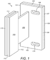
- a bracket 100 to form part of a building cladding assembly for cladding an external wall region of a building comprises generally a foot 101, a neck 102 extending generally perpendicular from foot 101 and a head 103 provided at an opposite end of neck 102 relative to foot 101.
- Foot 101 comprises a generally planar body having a front face 105 and a rear face 104.
- a pair of elongate slots 106 extend through foot 101 between faces 105, 104 to receive attachment bolts for securing bracket 100 in position within the cladding assembly.
- Neck 102 projects from front face 105 to separate head 103 from foot 101.
- foot 101, neck 102 and head 103 are formed integrally from aluminium so as to provide a generally rigid structure.
- Head 103 comprises a pair of opposed plates 111 that are spatially separated from one another to provide a mouth or gap region 110.
- One or both plates 111 are hingeably mounted together at rearward edge 112 such that plates 111 may be resiliently separated at edge 113 to increase the size of mouth 110 when mounting a flange or tail part of a rail system that in turn supports external cladding panels.
- head 103 may be formed from a single piece or component and comprise apertures to receive mounting bolts, pins, screws etc to secure bracket 100 to a rail or flange supporting the cladding panels.
- Other head 103 mechanisms may also be envisaged such as bayonet attachments, tongue and groove arrangements, click-lock attachments, push fit connections etc.
- Bracket 100 further comprises a thermal insulation layer 107 non-detachably mounted at foot rear face 104.
- the low thermal conductivity pad 107 is attached to rear face 104 via an adhesive such as an epoxy resin.
- Pad 107 also comprises a pair of elongate slots 114 being dimensioned and positioned to align respectively with the slots 106 (extending through foot 101) to receive attachment bolts.
- pad 107 comprises a material having a thermal conductivity of 0.010 to 0.030 W/(m ⁇ K) at a mean temperature of 23 to 26 °C and as measured as a compressive load of 13.79 kPa.
- pad 107 comprises CryogelTM available from Aspen Aerogels, Inc., NA 05132, USA.
- Pad 107 comprises a thickness in a plane perpendicular to face 104 of 5 mm to 10 mm and incorporates the silica aerogel material and a flexible fibre coating provided at a front face 108 and/or a rear face 109 of pad 107.
- An epoxy or thermal bonding agent is provided to permanently attach pad 107 via front face 108 to the rear face 104 of foot 101.
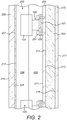
- bracket 100 is suitable for inclusion within an external rainscreen cladding system that is configured as an external wall structure of a building.
- the building interior is defined by an acoustic plaster board 215 that represents an inner leaf of the system having a rear face 217 that is internal facing within the building.
- Timber studs (beams) 204 are, in turn, mounted to an external facing mount face 216 of plaster board 215.
- a composite board 203 is secured to a front face 212 of timber studs 204 via a rear face 213. Accordingly, composite board 203, studs 204 and plaster board 215 represent inner leaf components of the external wall structure that may be regarded as an external wall of the building.
- a plurality of the brackets 100 are secured directly to a mount face 211 of composite boards 203 (alternatively termed cover boards) via mating contact with pad rear face 109.
- Each bracket 100 is secured to each cover board 203 via attachment bolts 200 that extend through foot 101 having bolt heads 201 positioned against front face 105. Accordingly, foot 101 is thermally isolated from cover board 203 via pad 107.
- Each bracket head 103 is secured to a tail member 206 that forms a rearward part of a panel mounting rail assembly 205.
- tail member 206 is formed as an elongate plate at least partially received within mouth 110 between bracket plates 111 so as to be gripped by frictional contact to securely mount rail 205 at brackets 100.
- tail member 206 is aligned generally parallel with bracket plates 111 and neck 102 and generally perpendicular to foot 101, insulation pad 107 and cover board 203.
- a rail head 207 also extends perpendicular to tail member 206.
- Rail head 207 comprises a mount face 214 for positioning in contact and attachment to a rear face 209 of a plurality of cladding panels 208.
- Each panel 208 comprises an external face 210 that represents an external-most part of the cladding assembly. Due to the respective lengths of bracket neck 102, head 103 and tail member 206, a spatial gap 202 is created between cover board 203 and cladding panels 208.
- a sheet insulation material may be positioned in the gap region 202 between cover board mount face 211 and external cladding panel rear face 209 to enhance the thermal partitioning of external cladding panels 208 and boards 203 and 215.
- Bracket insulation pad 107 is effective to minimise the thermal conductivity from the external cladding panels 208 to the cover board 203 at the region immediately behind foot 101. That is, the region of foot rear face 104 would otherwise provide a thermal bridge to between panels 208 and cover boards 203.
- bracket 100 thermally isolates the inner leaf plaster board 215.
- suitable low thermal conductivity washers or flanges may be provided under bolt heads 201 to thermally isolate bolts 200, 201 from the metallic foot 101.
- Figure 3 illustrates part of a steel framing system (SFS) cladding assembly.
- the building external wall is, in part, defined by a sub-frame assembly that comprises an innermost plaster board 215 as described with reference to figure 2 representing an innermost component of the assembly.
- a plurality of boards 215 may be provided as the innermost components of the assembly to provide acoustic insulation in addition to enhanced thermal insulation.
- the sub-frame assembly comprises a plurality of lightweight steel frame support members 300 attached directly to mount face 216 of plaster board 215.
- Cover boards 203 (alternatively termed a carrier boards) are mounted at an opposite side of the support members 300 via carrier board rear face 213.
- a spatial gap 304 is created between carrier boards rear face 213 and plaster boards mount face 216.
- a plurality of brackets 100 are then attached to a front face 211 of carrier boards 203 via contact between rear face 109 of insulation pad 107 and carrier board front face 211 as detailed with reference to figure 2 .
- carrier boards 203 are positioned intermediate brackets 100 and steel frame support members 300.
- the external-most layer of cladding panels 208 are mounted at the brackets 100 via the rail assembly 205 as described with reference to figure 2 .
- brackets 100 are secured to carrier board 203 via the same bolts 200, 201 as described with reference to figure 2 .
- bolts 200, 201 may be configured to extend through carrier boards 203 and into respective steel frame support members 300.
- frame support members 300 may be attached to carrier boards 203 via respective attachment bolts, screws, pins etc.
- a first layer of insulation material (not shown) may be positioned within gap region 202 and layered onto front face 211 of carrier boards 203.
- a second layer of insulation material (not shown) may be positioned within gap region 304 in contact between carrier board rear face 213 and/or cover board mount face 216.
- the present bracket assembly 100 is advantageous via the low thermal conductivity of pad 107 to provide a rainscreen cladding assembly of reduced total thickness between inner leaf board 215 and cladding panels 208.
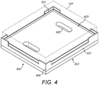
- pad 107 may be attached to bracket 100 via an intermediate adaptor indicated generally by reference 400.
- Adaptor 400 comprises a generally planar base 401 having an underside surface 402 and a support surface 403.
- Underside surface 402 is configured for positioning against and in contact with rear face 104 of foot 101 and comprises slots 405 positioned and dimensioned to correspond to slots 106 to receive attachment bolts so as to anchor bracket 100 to a suitable support substrate (i.e., boards 203).
- Base 401 comprises four shoulders 404 positioned at each corner 406 of base 401 that project upwardly a relatively short height/distance from support surface 403.
- Each shoulder 404 is formed as a relatively thin border section projecting from each corner 406 and extending a short lengthwise and widthwise distance along a part of the perimeter edge that defines support surface 403.
- a thickness of each shoulder 401 in the plane of support surface 403 is significantly less than a thickness of base 401 in a plane perpendicular to the plane of support surface 403. Accordingly, should any one of the shoulders 404 contact the substrate to which pad 107 is attached (for example under extreme compression) any thermal bridging effect through shoulders 404 is minimised and may be regarded as negligible.
- Shoulders 404 are configured to facilitate mounting of pad 107 on support surface 403 and are not intended to provide structural support and in particular to enhance the surface area contact between the bracket and the substrate board 203.
- the present bracket is constructed such that the pad rear face 109 provides exclusively the contact of the bracket 100 onto the support substrate 203 so as to maximise the thermal isolation function of the present bracket 100.
- Base 401 and in particular support surface 403 is configured to support pad 107 (illustrated with dashed lines) with pad 107 having a footprint or surface area corresponding to that of support surface 403 and the rear face 104 of bracket 100.
- the height of each shoulder 404 is appreciably less than a thickness of pad 107 (in the plane perpendicular to the plane of support surface 403) such that even under compression, pad 107 provides the exclusive contact and intermediate coupling between the support substrate 203 and the foot 101. That is under normal loading conditions, no part of each shoulder 404 is capable of contacting the support substrate.
- bracket 100 comprises the same features as described with reference to figure 1 including for example but not limited to the foot 101, neck 102, head 103 and associated components and features.
- an adaptor plate 500 is formed from a polypropylene thermoplastic and comprises a support surface 501 for positioning in contact against the rear face 104 of foot 101.
- Adaptor plate 500 also comprises an opposed underside surface 502 for positioning against insulation layer 107.
- a plurality of elongate slots 503 are formed through plate 500 between the opposed faces 501, 502.
- Plate 500 also comprises a raised edge 504 in the form of a lip or step extending around a perimeter of plate 500 along the lengthwise and widthwise extending perimeter edges.
- Plate 500 and edges 504 are dimensioned to sit over and about foot 101 such that foot 101 is at least partially housed within the recess defined by the upstanding adaptor plate edges 504.
- Elongate slots 503 are dimensioned so as to be co-aligned with slots 114 extending through foot 101 such that plate 500 is capable of being releasably mountable at foot 101 via the attachment bolts 200.
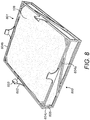
- bracket 100 also comprises a retainer indicated generally by reference 600.
- Retainer 600 comprises an open or cage-like structure to at least partially house pad 107 within an internal region indicated generally by reference 605.
- Region 605 is defined by a plurality of interconnect elongate struts that collectively define a containing frame having the cage-like structure.
- a set of lengthwise and widthwise extending struts 604b define a perimeter footprint of the retainer 600 with the lengthwise and widthwise struts 604b connected via corner struts 604c that together define a cuboidal open cage structure defining internal cavity region 605.
- the structure is supported by a set of bracing struts 604a that extend between struts 604b and across side faces of the retainer 600 and a rear face 800.
- An opposed contact face 801 of retainer 600 is generally open and is not obstructed by support struts 604a. Accordingly, with pad 107 located within cavity 605, the majority and in particular at least 80 or 90%, of the planar pad front face 108 is exposed for contact against the underside surface 502 of adaptor plate 500.
- Retainer 600 is releasably mountable at adaptor plate 500 via a set of attachment clips that project from retainer contact face 801.
- retainer 600 and in particular lengthwise and widthwise extending struts 604b comprises fingers 602 that project outward from and perpendicular to front face 108.
- Each finger 602 comprises a barb 603 directed inwardly towards pad front face 108.
- the length of each finger 602 is greater than a thickness of adaptor plate 500 so as to allow barbs 603 to be resiliently biased against and to hook over the raised adaptor plate edges 504 at plate face 501. Accordingly, with pad 107 housed within the cage-like retainer 600, pad 107 may be releasably clipped into contact with the bracket 100 via the mating of the retainer 600 onto adaptor plate 500 that is in turn secured to foot 101.
- the configuration of figures 5 to 7 is advantageous to provide thermal isolation of bracket 100 and composite board 203 via the intermediate positioned adaptor plate 500 and pad 107.
- Adaptor plate 500 also assists with the thermal isolation of bracket 100 and board 203 by providing an additional body of relatively low thermal conductivity between bracket 100 and board 203.
- the configuration of adaptor plate 500 and retainer 600 and in particular the cage-like structure of retainer 600 is advantageous to impart sufficient structural strength to the insulation layer 107 and to avoid loading induced deflection of the insulation layer assembly when mounted in position within a rainscreen system of figures 2 to 3 . That is, the retainer 600 and the adaptor plate 500 when coupled together are capable of transmitting load from the bracket 100 to the board 203 via attachment bolts 200. Accordingly, the subject invention is advantageous to provide both the desired structural attachment strength whilst achieving the desired thermal isolation of the various components of the rainscreen system of figures 2 to 3 .
- Example materials of the thermal isolating pad 107 are detailed below. The following examples are not limiting and the subject invention includes other alternative specific implementations having constituent materials that differ from those indicated. The relative concentrations of the constituent materials may also be selected to suit specific applications.
- Pad 107 comprises a material composition comprising components having thermal insulation characteristics including in particular silica particulate based materials.
- the material of pad 107 comprises at least one fibrous component.
- pad 107 comprises a foil cover provided at one or both faces.
- Table 1 - composition of pad 107 comprising CryogelTM Z available from Aspen Aerogels, Inc., MA 01532, USA. Chemical name CAS No.
- Bracket 100 comprising pad 107 according to the subject invention is advantageous to provide thermal performance enhancement over existing bracketry arrangements.
- the thermally isolating characteristic of the subject bracket 100 is achieved, in part, as the contact surface area of pad rear face 109 is at least equal to or greater than rear face 104 of foot 101 such that no part of foot 101 is capable of contacting the support substrate onto which bracket 100 is mechanically attached.
- pad 107 is capable of compression in use as bracket 100 is secured to the support substrate (board 203) via attachment bolts 200 without any reduction in the thermal conductivity resistance of pad 107.
- the present pad 107 is further advantageous to provide the desired structural performance and in particular to withstand shear and torsional forces transmitted through bracket 100 when bracket 100 is installed within an external cladding system according to figures 2 and 3 . That is, bracket 100 due to the choice of material of pad 107 is not configured to deflect appreciably in a vertical plane due to shear loading and also not to twist about its longitudinal axis due to torsional forces. Bracket 100 achieves the desired minimal deflection during use as it comprises a single pad only mounted at one end of the bracket. In one implementation, the pad comprises a density in a range 0.16 g/cm 3 to 0.2 g/cm 3 .
- pad 107 comprises at least one fire retardant component.
- pad 107 further comprises a material composition comprising silica particulate based components having thermal insulation characteristics and at least one fibrous component including for example fibrous glass.
- the fire retardant may comprise a metal oxide, a metal hydroxide, aluminium hydroxide, aluminium oxide, aluminium oxide hydroxide, or compounds including aluminium, phosphorous, nitrogen, antimony, chlorine, bromine, magnesium or zinc.
- the fire retardant comprises a clay within a polymer matrix including at least one organomodified clay.
- the clay comprises a montmorillonite.
- the fire retardant component comprises an inorganic compound such as antimony (III) oxide (Sb 2 O 3 ).
- Table 2 Composition of pad 107 comprising PyrogelTM XT-E available from Aspen Aerogels, Inc., MA 01532, USA. Chemical name CAS No. Concentration wt % Synthetic Amorphous Silica 7631-86-9 30-40% Methylsilylated Silica 68909-20-6 10-20% Fibrous Glass (textile grade) Not Applicable 40-50% Iron Oxide (iron (III) oxide) 1309-37-1 1-10% Aluminium Trihydrate (aluminium hydroxide) 21645-51-2 1-5% Optional additional components - Balance
- pad 107 is configured to withstand high temperature environment typically associated with a fire.
- the fire retardant is included at a concentration of 1 to 20% by weight.
- the flame retardant is configured to provide a pad 107 that does not disintegrate or decompose when exposed to temperatures of up to 650 °C.
- bracket 100 is configured to exhibit no or only minor deflection under loading (as would typically be encountered when bracket 100 is mounted within the cladding systems of figures 2 and 3 ) during and following exposure to fire.
- bracket 100 to satisfy further international standards such as EN 13501 (BR 135) - Fire Performance of External Thermal Insulation for Walls of Multistorey Buildings.
- bracket 100 comprising a material of example 2 (PyrogelTM) is capable of satisfying the (BR 135) BS 8414 and EN 1364-1/2 test criteria.
- pad 107 does not comprise a foil cover provided at one or both faces.
- Example 3 is a variation of example 2 in which pad 107 comprises at least one fire retardant component in addition to comprising silica particulate based components having thermal insulation characteristics and at least one fibrous component including for example fibrous glass.
- the fire retardant may comprise a silicate, belite, calcium monosilicate, calcium hydrosilicate, calcium metasilicate, calcium orthosilicate, grammite, or Ca 2 SiO 4 .
- Table 3 - Composition of pad 107 comprising SpaceloftTM A2 available from Aspen Aerogels, Inc., MA 01532, USA. Chemical name CAS No. Concentration wt % Synthetic Amorphous Silica 7631-86-9 30-40% Methylsilylated Silica 68909-20-6 5-15% Fibrous Glass (textile grade) Not Applicable 35-45% Calcium Silicate 13983-17-0 15-20%
- pad 107 is configured to withstand high temperature environment typically associated with a fire.
- the fire retardant is included at a concentration of 1 to 30% by weight.
- the flame retardant is configured to provide a pad 107 that does not disintegrate or decompose when exposed to temperatures of up to 650 °C.
- bracket 100 is configured to exhibit no or only minor deflection under loading (as would typically be encountered when bracket 100 is mounted within the cladding systems of figures 2 and 3 ) during and following exposure to fire.
- bracket 100 to satisfy further international standards such as EN 13501 (BR 135) - Fire Performance of External Thermal Insulation for Walls of Multistorey Buildings.
- bracket 100 comprising a material of example 3 (SpaceloftTM) is capable of satisfying the (BR 135) BS 8414, and EN 1364-1/2 test criteria as an A2 rating and ASTM E 84 fire test as a Class A rating.
- pad 107 does not comprise a foil cover provided at one or both faces.
- the present fire retardant pad 107 according to examples 2 and 3 is advantageous to withstand shear and torsional forces transmitted through bracket 100 (when mounted within an external cladding system according to figures 2 and 3 ) and not to deflect appreciably in a vertical plane due to shear loading and also not to twist about its longitudinal axis due to torsional forces during and after exposure fire at high temperatures of up to 650 °C.
- Such a configuration is achieved as the pad 107 does not disintegrate and maintains substantially its pre-fire physical and mechanical characteristics and composition.
Landscapes
- Engineering & Computer Science (AREA)
- Architecture (AREA)
- Civil Engineering (AREA)
- Structural Engineering (AREA)
- Physics & Mathematics (AREA)
- Electromagnetism (AREA)
- Acoustics & Sound (AREA)
- Building Environments (AREA)
Claims (15)
- Träger ("bracket") (100) zur Bildung eines Teils einer äußeren Gebäudeverkleidungsanordnung, wobei der Träger (100) umfasst:einen Fuß (101) mit einer Kontaktfläche (104), die an einem Strukturelement, das einen Teil der Verkleidungsanordnung oder eines Gebäudes bildet, befestigt werden kann;ein Befestigungselement (103) zum Befestigen des Trägers (100) an einer äußeren Verkleidungsplatte (208), einer Zwischenschiene (205) oder einem Montageflansch, der an der Verkleidungsplatte (208) festgemacht werden kann;eine Isolierschicht (107), die an der Kontaktfläche (104) des Fußes (101) befestigt werden kann, sodass sie zwischen dem Fuß (101) und dem Strukturelement sitzt, wobei eine Wärmeleitfähigkeit der Schicht (107) weniger als 0,09 W/(m·K) bei 10°C beträgt; undeine Halterung (600) mit einer offenen Struktur, um die Isolierschicht (107) zumindest teilweise zu umgeben und aufzunehmen,wobei die Halterung lösbar am Fuß (101) befestigt werden kann.
- Träger (100) wie in Anspruch 1 beansprucht, wobei die Wärmeleitfähigkeit weniger als 0,05 W/(m·K) bei 10°C; weniger als 0,03 W/(m·K) bei 10°C beträgt; oder wobei die Wärmeleitfähigkeit im Bereich von 0,01 bis 0,03 W/(m·K) bei 10°C liegt.
- Träger (100), wie in einem der vorhergehenden Ansprüche beansprucht, wobei die Isolierschicht (107) ein Isoliermaterial auf Faserbasis, ein Silica-Aerogel und/oder eine faserförmige Komponente umfasst.
- Träger (100), wie in einem der vorhergehenden Ansprüche beansprucht, wobei die Isolierschicht (107) umfasst:• synthetisches amorphes Siliciumdioxid;• methylsilyliertes Siliciumdioxid;• Polyethylen-Tetraphthalat oder Polyester;• faserförmiges Glas.
- Träger (100), wie in einem der Ansprüche 1 bis 3 beansprucht, wobei die Isolierschicht (107) mindestens eine flammhemmende Komponente umfasst.
- Träger (100), wie in Anspruch 5 beansprucht, wobei das flammhemmende Mittel eines oder eine Kombination aus dem Satz von Aluminiumhydroxid, Aluminiumoxidhydroxid, Antimon(III)-oxid, einem Ton, einem Ton innerhalb einer Polymermatrix, einem organomodifizierten Ton, Montmorillonit oder Verbindungen oder Materialien, die Aluminium, Phosphor, Stickstoff, Antimon, Chlorid, Brom, Magnesium, Zink, ein Silicat oder Calciumssilicat umfassen, umfasst.
- Träger (100), wie in einem der Ansprüche 1 bis 3 beansprucht, wobei die Isolierschicht (107) umfasst:• Siliciumdioxid;• eine faserförmige Komponente;• eine flammhemmende Komponente.
- Träger (100), wie in Anspruch 7 beansprucht, wobei das flammhemmende Mittel Eisenoxid und/oder Aluminiumtrihydrat (Aluminiumhydroxid Al(OH)3) umfasst.
- Träger (100), wie in Anspruch 7 beansprucht, wobei die flammhemmende Komponente Calciumsilicat umfasst.
- Träger (100), wie in Anspruch 9 beansprucht, umfassend:• 25 bis 45 Gew.-% synthetisches amorphes Siliciumdioxid;• 1 bis 25 Gew.-% methylsilyliertes Siliciumdioxid;• 30 bis 50 Gew.-% faserförmiges Glas;• 10 bis 25 Gew.-% Calciumsilicat.
- Träger (100), wie in einem der vorhergehenden Ansprüche beansprucht, weiterhin umfassend eine Adapterplatte (500), die zwischen der Kontaktfläche (104) des Fußes (101) und der Isolierschicht (107) angeordnet ist, wobei die Adapterplatte (500) ein thermoplastisches Material umfasst.
- Träger (100), wie in einem der vorhergehenden Ansprüche beansprucht, wobei die Halterung (600) Befestigungen (602) zur lösbaren Befestigung an dem Fuß (101) oder an der Adapterplatte (500) umfasst, um die Isolierschicht (107) in Kontakt mit dem Fuß (101) oder der Adapterplatte (500) lösbar zu montieren.
- Träger (100), wie in Anspruch 12 beansprucht, wobei die Halterung (600) eine käfigartige Struktur umfasst.
- Gebäudeverkleidungsanordnung zur Bildung eines Außenwandbereichs eines Gebäudes, umfassend:eine Vielzahl von Verkleidungsplatten (208), die in einer Kante-zu-Kante-Anordnung positionierbar sind, um eine äußere Verkleidungsschicht eines Gebäudes zu bilden;eine Vielzahl von Trägern (100), wie in einem der vorhergehenden Ansprüche beansprucht, wobei jedes Befestigungselement (103) jedes Trägers (100) an einer der Verkleidungsplatten (208), einer Zwischenschiene (205) oder einem Montageflansch, die/der an den Verkleidungsplatten (208) festgemacht werden kann, befestigt werden kann, wobei der Fuß (101) an einem Strukturelement, das einen Teil der Verkleidungsanordnung oder des Gebäudes bildet, über die jeweiligen Isolierschichten (107) festgemacht werden kann.
- Anordnung, wie Anspruch 14 beansprucht, weiterhin umfassend:eine Vielzahl von inneren Blattplatten (215), die angeordnet sind, um ein inneres Blatt der Anordnung zu bilden;einen Unterrahmen (300), der an einer Vielzahl der inneren Blattplatten (215) montiert werden kann,eine Vielzahl von Abdeckplatten (203), die an dem Unterrahmen (300) montiert werden können, um eine Unterverkleidungsschicht, die von den inneren Blattplatten (215) über den Unterrahmen (300) getrennt ist, bereitzustellen; undwobei die Träger (100) über die jeweiligen Isolierschichten (107) an den Abdeckplatten (203) montiert werden können, um die äußere Verkleidungsschicht räumlich von der Unterverkleidungsschicht zu trennen.
Priority Applications (1)
| Application Number | Priority Date | Filing Date | Title |
|---|---|---|---|
| EP20157415.9A EP3670782B1 (de) | 2015-06-26 | 2016-06-24 | Verkleidungsvorrichtung für vorgehängte fassade |
Applications Claiming Priority (4)
| Application Number | Priority Date | Filing Date | Title |
|---|---|---|---|
| GBGB1511292.3A GB201511292D0 (en) | 2015-06-26 | 2015-06-26 | Rainscreen cladding apparatus |
| GBGB1600576.1A GB201600576D0 (en) | 2016-01-12 | 2016-01-12 | Rainscreen cladding apparatus |
| GBGB1607808.1A GB201607808D0 (en) | 2016-05-04 | 2016-05-04 | Rainscreen cladding apparatus |
| PCT/GB2016/051895 WO2016207648A1 (en) | 2015-06-26 | 2016-06-24 | Rainscreen cladding apparatus |
Related Child Applications (1)
| Application Number | Title | Priority Date | Filing Date |
|---|---|---|---|
| EP20157415.9A Division EP3670782B1 (de) | 2015-06-26 | 2016-06-24 | Verkleidungsvorrichtung für vorgehängte fassade |
Publications (2)
| Publication Number | Publication Date |
|---|---|
| EP3314069A1 EP3314069A1 (de) | 2018-05-02 |
| EP3314069B1 true EP3314069B1 (de) | 2020-02-19 |
Family
ID=56263989
Family Applications (2)
| Application Number | Title | Priority Date | Filing Date |
|---|---|---|---|
| EP20157415.9A Active EP3670782B1 (de) | 2015-06-26 | 2016-06-24 | Verkleidungsvorrichtung für vorgehängte fassade |
| EP16732723.8A Active EP3314069B1 (de) | 2015-06-26 | 2016-06-24 | Verkleidungsvorrichtung für vorgehängte fassade |
Family Applications Before (1)
| Application Number | Title | Priority Date | Filing Date |
|---|---|---|---|
| EP20157415.9A Active EP3670782B1 (de) | 2015-06-26 | 2016-06-24 | Verkleidungsvorrichtung für vorgehängte fassade |
Country Status (3)
| Country | Link |
|---|---|
| EP (2) | EP3670782B1 (de) |
| GB (2) | GB2559905B (de) |
| WO (1) | WO2016207648A1 (de) |
Families Citing this family (7)
| Publication number | Priority date | Publication date | Assignee | Title |
|---|---|---|---|---|
| LT6656B (lt) * | 2017-12-08 | 2019-09-25 | UAB "Serfas" | Vėdinamo fasado laikiklis |
| EP3686370A1 (de) | 2019-01-25 | 2020-07-29 | Pittsburgh Corning Europe NV | Befestigungssystem für fassadenverkleidungen |
| EP3789559A1 (de) * | 2019-09-04 | 2021-03-10 | Benx Limited | Feuerbeständige abstandkörper zur verwendung in strukturverkleidung |
| CN111217570A (zh) * | 2020-01-15 | 2020-06-02 | 中国十七冶集团有限公司 | 一种保温胶泥反射隔热涂料外墙保温系统的制备方法 |
| GB2583558B (en) | 2020-01-29 | 2021-12-22 | Sfs Group Fastening Tech Ltd | Thermal insulation pad |
| ES2928092B2 (es) * | 2021-05-10 | 2023-04-13 | Sist Avanzados De Fachadas Ventiladas S L | Elemento de aislamiento termico para dispositivo de anclaje de fachada ventilada, asi como dichos dispositivo y fachada |
| EP4187042A1 (de) * | 2021-11-29 | 2023-05-31 | Stoyanov, Damian Vassilev | Halteklammer für fassadenstrukturen und system zur befestigung von fassadenstrukturen |
Family Cites Families (9)
| Publication number | Priority date | Publication date | Assignee | Title |
|---|---|---|---|---|
| US8973334B2 (en) * | 2010-12-06 | 2015-03-10 | Scott Croasdale | System and methods for thermal isolation of components used |
| US8429866B2 (en) * | 2010-12-06 | 2013-04-30 | Douglas James Knight | Modular system for cladding exterior walls of a structure and insulating the structure walls |
| DE102010061139B4 (de) * | 2010-12-09 | 2022-01-20 | Mofix Montage- Und Handels-Gmbh | Wärmebrückenfreier Adapter mit einer Anschlusseinheit zur Befestigung von Gegenständen an Wänden sowie ein Verfahren zur Befestigung von Gegenständen mit einem wärmebrückenfreien Adapter an Wänden |
| CA2784018C (en) * | 2012-07-26 | 2019-12-24 | Engineered Assemblies Inc. | Thermal clip system and apparatus for a building wall assembly |
| DE102012016025B4 (de) * | 2012-08-13 | 2020-02-27 | Nauth Sl Fassadentechnik Gmbh | Wandhalter zur Fixierung einer vorgehängten Fassade |
| CA2820970C (en) * | 2013-03-14 | 2020-09-15 | Douglas James Knight | Improved modular system for continuously insulating exterior walls of a structure and securing exterior cladding to the structure |
| US9140007B2 (en) | 2013-04-23 | 2015-09-22 | MOTO Extrusions, Inc. | Rain screen framing system |
| CA2850715C (en) * | 2013-05-02 | 2017-09-05 | Donald George White | Thermal break wall systems and thermal adjustable clip |
| US8910441B1 (en) | 2013-06-18 | 2014-12-16 | Kenneth Hunter | Cladding attachment system to enable an exterior continuous insulation barrier |
-
2016
- 2016-06-24 EP EP20157415.9A patent/EP3670782B1/de active Active
- 2016-06-24 GB GB1806058.2A patent/GB2559905B/en active Active
- 2016-06-24 WO PCT/GB2016/051895 patent/WO2016207648A1/en not_active Ceased
- 2016-06-24 GB GB1611019.9A patent/GB2541513B/en active Active
- 2016-06-24 EP EP16732723.8A patent/EP3314069B1/de active Active
Non-Patent Citations (1)
| Title |
|---|
| None * |
Also Published As
| Publication number | Publication date |
|---|---|
| EP3670782B1 (de) | 2024-11-27 |
| EP3314069A1 (de) | 2018-05-02 |
| EP3670782A1 (de) | 2020-06-24 |
| GB201806058D0 (en) | 2018-05-30 |
| GB2559905B (en) | 2020-02-12 |
| GB2541513B (en) | 2018-05-23 |
| GB2541513A (en) | 2017-02-22 |
| GB201611019D0 (en) | 2016-08-10 |
| GB2559905A (en) | 2018-08-22 |
| WO2016207648A1 (en) | 2016-12-29 |
Similar Documents
| Publication | Publication Date | Title |
|---|---|---|
| EP3314069B1 (de) | Verkleidungsvorrichtung für vorgehängte fassade | |
| CA2784018C (en) | Thermal clip system and apparatus for a building wall assembly | |
| US7946384B2 (en) | Acoustical and firewall barrier assembly | |
| US9206609B2 (en) | Thermal break wall systems and thermal adjustable clip | |
| US20110146173A1 (en) | Wall system for a building | |
| EP3296480A1 (de) | Wärme- und schallisolations- und dichtungssystem für geriffelte deckkonstruktionen | |
| WO2008110818A1 (en) | Wall insulation system | |
| JP2000136580A (ja) | 建物構造及び該建物構造を用いたユニット建物 | |
| KR20190038708A (ko) | 내진 성능을 갖춘 열교 차단형 단열 벽 패널 구조체 | |
| JP6235260B2 (ja) | 天井材および天井材の施工方法 | |
| JP5435888B2 (ja) | 天井構造及びその施工方法 | |
| JPS637609Y2 (de) | ||
| JP6904711B2 (ja) | 天井部材および天井構造 | |
| GB2541918B (en) | Non-combustible low emissivity composite board | |
| AU2021214893B2 (en) | Thermal insulation pad | |
| KR102295568B1 (ko) | 암면 패널을 이용한 타일 대용 사용 가능 벽체 시공 방법 | |
| JPH10331383A (ja) | 硬質壁材の取付構造 | |
| JP2021028447A (ja) | 耐火木質部材 | |
| JP4559168B2 (ja) | 屋根構造 | |
| JP2002256639A (ja) | 間仕切壁構造 | |
| JP2001123641A (ja) | 外装パネル | |
| CA3213534A1 (en) | Framing brackets and systems for shipping container interior | |
| JP2000234404A (ja) | 壁内通気構造 | |
| JP2006118167A (ja) | 遮熱材の設置構造 | |
| CA2756963A1 (en) | Plenum barrier system |
Legal Events
| Date | Code | Title | Description |
|---|---|---|---|
| STAA | Information on the status of an ep patent application or granted ep patent |
Free format text: STATUS: THE INTERNATIONAL PUBLICATION HAS BEEN MADE |
|
| PUAI | Public reference made under article 153(3) epc to a published international application that has entered the european phase |
Free format text: ORIGINAL CODE: 0009012 |
|
| STAA | Information on the status of an ep patent application or granted ep patent |
Free format text: STATUS: REQUEST FOR EXAMINATION WAS MADE |
|
| 17P | Request for examination filed |
Effective date: 20171113 |
|
| AK | Designated contracting states |
Kind code of ref document: A1 Designated state(s): AL AT BE BG CH CY CZ DE DK EE ES FI FR GB GR HR HU IE IS IT LI LT LU LV MC MK MT NL NO PL PT RO RS SE SI SK SM TR |
|
| AX | Request for extension of the european patent |
Extension state: BA ME |
|
| DAV | Request for validation of the european patent (deleted) | ||
| DAX | Request for extension of the european patent (deleted) | ||
| STAA | Information on the status of an ep patent application or granted ep patent |
Free format text: STATUS: EXAMINATION IS IN PROGRESS |
|
| 17Q | First examination report despatched |
Effective date: 20190318 |
|
| GRAP | Despatch of communication of intention to grant a patent |
Free format text: ORIGINAL CODE: EPIDOSNIGR1 |
|
| STAA | Information on the status of an ep patent application or granted ep patent |
Free format text: STATUS: GRANT OF PATENT IS INTENDED |
|
| INTG | Intention to grant announced |
Effective date: 20191017 |
|
| GRAS | Grant fee paid |
Free format text: ORIGINAL CODE: EPIDOSNIGR3 |
|
| GRAA | (expected) grant |
Free format text: ORIGINAL CODE: 0009210 |
|
| STAA | Information on the status of an ep patent application or granted ep patent |
Free format text: STATUS: THE PATENT HAS BEEN GRANTED |
|
| AK | Designated contracting states |
Kind code of ref document: B1 Designated state(s): AL AT BE BG CH CY CZ DE DK EE ES FI FR GB GR HR HU IE IS IT LI LT LU LV MC MK MT NL NO PL PT RO RS SE SI SK SM TR |
|
| REG | Reference to a national code |
Ref country code: CH Ref legal event code: EP |
|
| REG | Reference to a national code |
Ref country code: DE Ref legal event code: R096 Ref document number: 602016030065 Country of ref document: DE |
|
| REG | Reference to a national code |
Ref country code: AT Ref legal event code: REF Ref document number: 1235118 Country of ref document: AT Kind code of ref document: T Effective date: 20200315 |
|
| REG | Reference to a national code |
Ref country code: IE Ref legal event code: FG4D |
|
| REG | Reference to a national code |
Ref country code: CH Ref legal event code: NV Representative=s name: E. BLUM AND CO. AG PATENT- UND MARKENANWAELTE , CH |
|
| REG | Reference to a national code |
Ref country code: NL Ref legal event code: MP Effective date: 20200219 |
|
| PG25 | Lapsed in a contracting state [announced via postgrant information from national office to epo] |
Ref country code: FI Free format text: LAPSE BECAUSE OF FAILURE TO SUBMIT A TRANSLATION OF THE DESCRIPTION OR TO PAY THE FEE WITHIN THE PRESCRIBED TIME-LIMIT Effective date: 20200219 Ref country code: NO Free format text: LAPSE BECAUSE OF FAILURE TO SUBMIT A TRANSLATION OF THE DESCRIPTION OR TO PAY THE FEE WITHIN THE PRESCRIBED TIME-LIMIT Effective date: 20200519 Ref country code: RS Free format text: LAPSE BECAUSE OF FAILURE TO SUBMIT A TRANSLATION OF THE DESCRIPTION OR TO PAY THE FEE WITHIN THE PRESCRIBED TIME-LIMIT Effective date: 20200219 |
|
| REG | Reference to a national code |
Ref country code: LT Ref legal event code: MG4D |
|
| PG25 | Lapsed in a contracting state [announced via postgrant information from national office to epo] |
Ref country code: GR Free format text: LAPSE BECAUSE OF FAILURE TO SUBMIT A TRANSLATION OF THE DESCRIPTION OR TO PAY THE FEE WITHIN THE PRESCRIBED TIME-LIMIT Effective date: 20200520 Ref country code: HR Free format text: LAPSE BECAUSE OF FAILURE TO SUBMIT A TRANSLATION OF THE DESCRIPTION OR TO PAY THE FEE WITHIN THE PRESCRIBED TIME-LIMIT Effective date: 20200219 Ref country code: LV Free format text: LAPSE BECAUSE OF FAILURE TO SUBMIT A TRANSLATION OF THE DESCRIPTION OR TO PAY THE FEE WITHIN THE PRESCRIBED TIME-LIMIT Effective date: 20200219 Ref country code: SE Free format text: LAPSE BECAUSE OF FAILURE TO SUBMIT A TRANSLATION OF THE DESCRIPTION OR TO PAY THE FEE WITHIN THE PRESCRIBED TIME-LIMIT Effective date: 20200219 Ref country code: IS Free format text: LAPSE BECAUSE OF FAILURE TO SUBMIT A TRANSLATION OF THE DESCRIPTION OR TO PAY THE FEE WITHIN THE PRESCRIBED TIME-LIMIT Effective date: 20200619 Ref country code: BG Free format text: LAPSE BECAUSE OF FAILURE TO SUBMIT A TRANSLATION OF THE DESCRIPTION OR TO PAY THE FEE WITHIN THE PRESCRIBED TIME-LIMIT Effective date: 20200519 |
|
| PG25 | Lapsed in a contracting state [announced via postgrant information from national office to epo] |
Ref country code: NL Free format text: LAPSE BECAUSE OF FAILURE TO SUBMIT A TRANSLATION OF THE DESCRIPTION OR TO PAY THE FEE WITHIN THE PRESCRIBED TIME-LIMIT Effective date: 20200219 |
|
| PG25 | Lapsed in a contracting state [announced via postgrant information from national office to epo] |
Ref country code: LT Free format text: LAPSE BECAUSE OF FAILURE TO SUBMIT A TRANSLATION OF THE DESCRIPTION OR TO PAY THE FEE WITHIN THE PRESCRIBED TIME-LIMIT Effective date: 20200219 Ref country code: SM Free format text: LAPSE BECAUSE OF FAILURE TO SUBMIT A TRANSLATION OF THE DESCRIPTION OR TO PAY THE FEE WITHIN THE PRESCRIBED TIME-LIMIT Effective date: 20200219 Ref country code: EE Free format text: LAPSE BECAUSE OF FAILURE TO SUBMIT A TRANSLATION OF THE DESCRIPTION OR TO PAY THE FEE WITHIN THE PRESCRIBED TIME-LIMIT Effective date: 20200219 Ref country code: DK Free format text: LAPSE BECAUSE OF FAILURE TO SUBMIT A TRANSLATION OF THE DESCRIPTION OR TO PAY THE FEE WITHIN THE PRESCRIBED TIME-LIMIT Effective date: 20200219 Ref country code: RO Free format text: LAPSE BECAUSE OF FAILURE TO SUBMIT A TRANSLATION OF THE DESCRIPTION OR TO PAY THE FEE WITHIN THE PRESCRIBED TIME-LIMIT Effective date: 20200219 Ref country code: CZ Free format text: LAPSE BECAUSE OF FAILURE TO SUBMIT A TRANSLATION OF THE DESCRIPTION OR TO PAY THE FEE WITHIN THE PRESCRIBED TIME-LIMIT Effective date: 20200219 Ref country code: ES Free format text: LAPSE BECAUSE OF FAILURE TO SUBMIT A TRANSLATION OF THE DESCRIPTION OR TO PAY THE FEE WITHIN THE PRESCRIBED TIME-LIMIT Effective date: 20200219 Ref country code: PT Free format text: LAPSE BECAUSE OF FAILURE TO SUBMIT A TRANSLATION OF THE DESCRIPTION OR TO PAY THE FEE WITHIN THE PRESCRIBED TIME-LIMIT Effective date: 20200712 Ref country code: SK Free format text: LAPSE BECAUSE OF FAILURE TO SUBMIT A TRANSLATION OF THE DESCRIPTION OR TO PAY THE FEE WITHIN THE PRESCRIBED TIME-LIMIT Effective date: 20200219 |
|
| REG | Reference to a national code |
Ref country code: AT Ref legal event code: MK05 Ref document number: 1235118 Country of ref document: AT Kind code of ref document: T Effective date: 20200219 |
|
| REG | Reference to a national code |
Ref country code: DE Ref legal event code: R097 Ref document number: 602016030065 Country of ref document: DE |
|
| PLBE | No opposition filed within time limit |
Free format text: ORIGINAL CODE: 0009261 |
|
| STAA | Information on the status of an ep patent application or granted ep patent |
Free format text: STATUS: NO OPPOSITION FILED WITHIN TIME LIMIT |
|
| 26N | No opposition filed |
Effective date: 20201120 |
|
| PG25 | Lapsed in a contracting state [announced via postgrant information from national office to epo] |
Ref country code: IT Free format text: LAPSE BECAUSE OF FAILURE TO SUBMIT A TRANSLATION OF THE DESCRIPTION OR TO PAY THE FEE WITHIN THE PRESCRIBED TIME-LIMIT Effective date: 20200219 Ref country code: AT Free format text: LAPSE BECAUSE OF FAILURE TO SUBMIT A TRANSLATION OF THE DESCRIPTION OR TO PAY THE FEE WITHIN THE PRESCRIBED TIME-LIMIT Effective date: 20200219 Ref country code: MC Free format text: LAPSE BECAUSE OF FAILURE TO SUBMIT A TRANSLATION OF THE DESCRIPTION OR TO PAY THE FEE WITHIN THE PRESCRIBED TIME-LIMIT Effective date: 20200219 |
|
| PG25 | Lapsed in a contracting state [announced via postgrant information from national office to epo] |
Ref country code: PL Free format text: LAPSE BECAUSE OF FAILURE TO SUBMIT A TRANSLATION OF THE DESCRIPTION OR TO PAY THE FEE WITHIN THE PRESCRIBED TIME-LIMIT Effective date: 20200219 Ref country code: SI Free format text: LAPSE BECAUSE OF FAILURE TO SUBMIT A TRANSLATION OF THE DESCRIPTION OR TO PAY THE FEE WITHIN THE PRESCRIBED TIME-LIMIT Effective date: 20200219 |
|
| GBPC | Gb: european patent ceased through non-payment of renewal fee |
Effective date: 20200624 |
|
| PG25 | Lapsed in a contracting state [announced via postgrant information from national office to epo] |
Ref country code: LU Free format text: LAPSE BECAUSE OF NON-PAYMENT OF DUE FEES Effective date: 20200624 |
|
| REG | Reference to a national code |
Ref country code: BE Ref legal event code: MM Effective date: 20200630 |
|
| PG25 | Lapsed in a contracting state [announced via postgrant information from national office to epo] |
Ref country code: IE Free format text: LAPSE BECAUSE OF NON-PAYMENT OF DUE FEES Effective date: 20200624 Ref country code: GB Free format text: LAPSE BECAUSE OF NON-PAYMENT OF DUE FEES Effective date: 20200624 |
|
| PG25 | Lapsed in a contracting state [announced via postgrant information from national office to epo] |
Ref country code: BE Free format text: LAPSE BECAUSE OF NON-PAYMENT OF DUE FEES Effective date: 20200630 |
|
| PG25 | Lapsed in a contracting state [announced via postgrant information from national office to epo] |
Ref country code: TR Free format text: LAPSE BECAUSE OF FAILURE TO SUBMIT A TRANSLATION OF THE DESCRIPTION OR TO PAY THE FEE WITHIN THE PRESCRIBED TIME-LIMIT Effective date: 20200219 Ref country code: MT Free format text: LAPSE BECAUSE OF FAILURE TO SUBMIT A TRANSLATION OF THE DESCRIPTION OR TO PAY THE FEE WITHIN THE PRESCRIBED TIME-LIMIT Effective date: 20200219 Ref country code: CY Free format text: LAPSE BECAUSE OF FAILURE TO SUBMIT A TRANSLATION OF THE DESCRIPTION OR TO PAY THE FEE WITHIN THE PRESCRIBED TIME-LIMIT Effective date: 20200219 |
|
| PG25 | Lapsed in a contracting state [announced via postgrant information from national office to epo] |
Ref country code: MK Free format text: LAPSE BECAUSE OF FAILURE TO SUBMIT A TRANSLATION OF THE DESCRIPTION OR TO PAY THE FEE WITHIN THE PRESCRIBED TIME-LIMIT Effective date: 20200219 Ref country code: AL Free format text: LAPSE BECAUSE OF FAILURE TO SUBMIT A TRANSLATION OF THE DESCRIPTION OR TO PAY THE FEE WITHIN THE PRESCRIBED TIME-LIMIT Effective date: 20200219 |
|
| P01 | Opt-out of the competence of the unified patent court (upc) registered |
Effective date: 20230527 |
|
| PGFP | Annual fee paid to national office [announced via postgrant information from national office to epo] |
Ref country code: FR Payment date: 20250627 Year of fee payment: 10 |
|
| PGFP | Annual fee paid to national office [announced via postgrant information from national office to epo] |
Ref country code: DE Payment date: 20250630 Year of fee payment: 10 |
|
| PGFP | Annual fee paid to national office [announced via postgrant information from national office to epo] |
Ref country code: CH Payment date: 20250701 Year of fee payment: 10 |