EP3312901A1 - Sekundärbatterie - Google Patents
Sekundärbatterie Download PDFInfo
- Publication number
- EP3312901A1 EP3312901A1 EP17195098.3A EP17195098A EP3312901A1 EP 3312901 A1 EP3312901 A1 EP 3312901A1 EP 17195098 A EP17195098 A EP 17195098A EP 3312901 A1 EP3312901 A1 EP 3312901A1
- Authority
- EP
- European Patent Office
- Prior art keywords
- plate
- insulation member
- upper insulation
- secondary battery
- coupled
- Prior art date
- Legal status (The legal status is an assumption and is not a legal conclusion. Google has not performed a legal analysis and makes no representation as to the accuracy of the status listed.)
- Granted
Links
Images



Classifications
-
- H—ELECTRICITY
- H01—ELECTRIC ELEMENTS
- H01M—PROCESSES OR MEANS, e.g. BATTERIES, FOR THE DIRECT CONVERSION OF CHEMICAL ENERGY INTO ELECTRICAL ENERGY
- H01M50/00—Constructional details or processes of manufacture of the non-active parts of electrochemical cells other than fuel cells, e.g. hybrid cells
- H01M50/30—Arrangements for facilitating escape of gases
- H01M50/35—Gas exhaust passages comprising elongated, tortuous or labyrinth-shaped exhaust passages
-
- H—ELECTRICITY
- H01—ELECTRIC ELEMENTS
- H01M—PROCESSES OR MEANS, e.g. BATTERIES, FOR THE DIRECT CONVERSION OF CHEMICAL ENERGY INTO ELECTRICAL ENERGY
- H01M10/00—Secondary cells; Manufacture thereof
- H01M10/05—Accumulators with non-aqueous electrolyte
-
- H—ELECTRICITY
- H01—ELECTRIC ELEMENTS
- H01M—PROCESSES OR MEANS, e.g. BATTERIES, FOR THE DIRECT CONVERSION OF CHEMICAL ENERGY INTO ELECTRICAL ENERGY
- H01M10/00—Secondary cells; Manufacture thereof
- H01M10/05—Accumulators with non-aqueous electrolyte
- H01M10/058—Construction or manufacture
-
- H—ELECTRICITY
- H01—ELECTRIC ELEMENTS
- H01M—PROCESSES OR MEANS, e.g. BATTERIES, FOR THE DIRECT CONVERSION OF CHEMICAL ENERGY INTO ELECTRICAL ENERGY
- H01M50/00—Constructional details or processes of manufacture of the non-active parts of electrochemical cells other than fuel cells, e.g. hybrid cells
- H01M50/10—Primary casings; Jackets or wrappings
-
- H—ELECTRICITY
- H01—ELECTRIC ELEMENTS
- H01M—PROCESSES OR MEANS, e.g. BATTERIES, FOR THE DIRECT CONVERSION OF CHEMICAL ENERGY INTO ELECTRICAL ENERGY
- H01M50/00—Constructional details or processes of manufacture of the non-active parts of electrochemical cells other than fuel cells, e.g. hybrid cells
- H01M50/10—Primary casings; Jackets or wrappings
- H01M50/102—Primary casings; Jackets or wrappings characterised by their shape or physical structure
- H01M50/103—Primary casings; Jackets or wrappings characterised by their shape or physical structure prismatic or rectangular
-
- H—ELECTRICITY
- H01—ELECTRIC ELEMENTS
- H01M—PROCESSES OR MEANS, e.g. BATTERIES, FOR THE DIRECT CONVERSION OF CHEMICAL ENERGY INTO ELECTRICAL ENERGY
- H01M50/00—Constructional details or processes of manufacture of the non-active parts of electrochemical cells other than fuel cells, e.g. hybrid cells
- H01M50/10—Primary casings; Jackets or wrappings
- H01M50/147—Lids or covers
-
- H—ELECTRICITY
- H01—ELECTRIC ELEMENTS
- H01M—PROCESSES OR MEANS, e.g. BATTERIES, FOR THE DIRECT CONVERSION OF CHEMICAL ENERGY INTO ELECTRICAL ENERGY
- H01M50/00—Constructional details or processes of manufacture of the non-active parts of electrochemical cells other than fuel cells, e.g. hybrid cells
- H01M50/10—Primary casings; Jackets or wrappings
- H01M50/147—Lids or covers
- H01M50/148—Lids or covers characterised by their shape
- H01M50/15—Lids or covers characterised by their shape for prismatic or rectangular cells
-
- H—ELECTRICITY
- H01—ELECTRIC ELEMENTS
- H01M—PROCESSES OR MEANS, e.g. BATTERIES, FOR THE DIRECT CONVERSION OF CHEMICAL ENERGY INTO ELECTRICAL ENERGY
- H01M50/00—Constructional details or processes of manufacture of the non-active parts of electrochemical cells other than fuel cells, e.g. hybrid cells
- H01M50/10—Primary casings; Jackets or wrappings
- H01M50/147—Lids or covers
- H01M50/148—Lids or covers characterised by their shape
- H01M50/154—Lid or cover comprising an axial bore for receiving a central current collector
-
- H—ELECTRICITY
- H01—ELECTRIC ELEMENTS
- H01M—PROCESSES OR MEANS, e.g. BATTERIES, FOR THE DIRECT CONVERSION OF CHEMICAL ENERGY INTO ELECTRICAL ENERGY
- H01M50/00—Constructional details or processes of manufacture of the non-active parts of electrochemical cells other than fuel cells, e.g. hybrid cells
- H01M50/30—Arrangements for facilitating escape of gases
-
- H—ELECTRICITY
- H01—ELECTRIC ELEMENTS
- H01M—PROCESSES OR MEANS, e.g. BATTERIES, FOR THE DIRECT CONVERSION OF CHEMICAL ENERGY INTO ELECTRICAL ENERGY
- H01M50/00—Constructional details or processes of manufacture of the non-active parts of electrochemical cells other than fuel cells, e.g. hybrid cells
- H01M50/30—Arrangements for facilitating escape of gases
- H01M50/342—Non-re-sealable arrangements
-
- H—ELECTRICITY
- H01—ELECTRIC ELEMENTS
- H01M—PROCESSES OR MEANS, e.g. BATTERIES, FOR THE DIRECT CONVERSION OF CHEMICAL ENERGY INTO ELECTRICAL ENERGY
- H01M50/00—Constructional details or processes of manufacture of the non-active parts of electrochemical cells other than fuel cells, e.g. hybrid cells
- H01M50/30—Arrangements for facilitating escape of gases
- H01M50/342—Non-re-sealable arrangements
- H01M50/3425—Non-re-sealable arrangements in the form of rupturable membranes or weakened parts, e.g. pierced with the aid of a sharp member
-
- H—ELECTRICITY
- H01—ELECTRIC ELEMENTS
- H01M—PROCESSES OR MEANS, e.g. BATTERIES, FOR THE DIRECT CONVERSION OF CHEMICAL ENERGY INTO ELECTRICAL ENERGY
- H01M50/00—Constructional details or processes of manufacture of the non-active parts of electrochemical cells other than fuel cells, e.g. hybrid cells
- H01M50/50—Current conducting connections for cells or batteries
- H01M50/543—Terminals
-
- H—ELECTRICITY
- H01—ELECTRIC ELEMENTS
- H01M—PROCESSES OR MEANS, e.g. BATTERIES, FOR THE DIRECT CONVERSION OF CHEMICAL ENERGY INTO ELECTRICAL ENERGY
- H01M50/00—Constructional details or processes of manufacture of the non-active parts of electrochemical cells other than fuel cells, e.g. hybrid cells
- H01M50/50—Current conducting connections for cells or batteries
- H01M50/543—Terminals
- H01M50/547—Terminals characterised by the disposition of the terminals on the cells
- H01M50/55—Terminals characterised by the disposition of the terminals on the cells on the same side of the cell
-
- H—ELECTRICITY
- H01—ELECTRIC ELEMENTS
- H01M—PROCESSES OR MEANS, e.g. BATTERIES, FOR THE DIRECT CONVERSION OF CHEMICAL ENERGY INTO ELECTRICAL ENERGY
- H01M50/00—Constructional details or processes of manufacture of the non-active parts of electrochemical cells other than fuel cells, e.g. hybrid cells
- H01M50/50—Current conducting connections for cells or batteries
- H01M50/543—Terminals
- H01M50/552—Terminals characterised by their shape
- H01M50/553—Terminals adapted for prismatic, pouch or rectangular cells
-
- H—ELECTRICITY
- H01—ELECTRIC ELEMENTS
- H01M—PROCESSES OR MEANS, e.g. BATTERIES, FOR THE DIRECT CONVERSION OF CHEMICAL ENERGY INTO ELECTRICAL ENERGY
- H01M50/00—Constructional details or processes of manufacture of the non-active parts of electrochemical cells other than fuel cells, e.g. hybrid cells
- H01M50/50—Current conducting connections for cells or batteries
- H01M50/572—Means for preventing undesired use or discharge
- H01M50/574—Devices or arrangements for the interruption of current
- H01M50/578—Devices or arrangements for the interruption of current in response to pressure
-
- H—ELECTRICITY
- H01—ELECTRIC ELEMENTS
- H01M—PROCESSES OR MEANS, e.g. BATTERIES, FOR THE DIRECT CONVERSION OF CHEMICAL ENERGY INTO ELECTRICAL ENERGY
- H01M50/00—Constructional details or processes of manufacture of the non-active parts of electrochemical cells other than fuel cells, e.g. hybrid cells
- H01M50/50—Current conducting connections for cells or batteries
- H01M50/572—Means for preventing undesired use or discharge
- H01M50/584—Means for preventing undesired use or discharge for preventing incorrect connections inside or outside the batteries
- H01M50/586—Means for preventing undesired use or discharge for preventing incorrect connections inside or outside the batteries inside the batteries, e.g. incorrect connections of electrodes
-
- H—ELECTRICITY
- H01—ELECTRIC ELEMENTS
- H01M—PROCESSES OR MEANS, e.g. BATTERIES, FOR THE DIRECT CONVERSION OF CHEMICAL ENERGY INTO ELECTRICAL ENERGY
- H01M50/00—Constructional details or processes of manufacture of the non-active parts of electrochemical cells other than fuel cells, e.g. hybrid cells
- H01M50/50—Current conducting connections for cells or batteries
- H01M50/572—Means for preventing undesired use or discharge
- H01M50/584—Means for preventing undesired use or discharge for preventing incorrect connections inside or outside the batteries
- H01M50/59—Means for preventing undesired use or discharge for preventing incorrect connections inside or outside the batteries characterised by the protection means
- H01M50/593—Spacers; Insulating plates
-
- H—ELECTRICITY
- H01—ELECTRIC ELEMENTS
- H01M—PROCESSES OR MEANS, e.g. BATTERIES, FOR THE DIRECT CONVERSION OF CHEMICAL ENERGY INTO ELECTRICAL ENERGY
- H01M10/00—Secondary cells; Manufacture thereof
- H01M10/05—Accumulators with non-aqueous electrolyte
- H01M10/052—Li-accumulators
- H01M10/0525—Rocking-chair batteries, i.e. batteries with lithium insertion or intercalation in both electrodes; Lithium-ion batteries
-
- H—ELECTRICITY
- H01—ELECTRIC ELEMENTS
- H01M—PROCESSES OR MEANS, e.g. BATTERIES, FOR THE DIRECT CONVERSION OF CHEMICAL ENERGY INTO ELECTRICAL ENERGY
- H01M2200/00—Safety devices for primary or secondary batteries
- H01M2200/20—Pressure-sensitive devices
-
- H—ELECTRICITY
- H01—ELECTRIC ELEMENTS
- H01M—PROCESSES OR MEANS, e.g. BATTERIES, FOR THE DIRECT CONVERSION OF CHEMICAL ENERGY INTO ELECTRICAL ENERGY
- H01M50/00—Constructional details or processes of manufacture of the non-active parts of electrochemical cells other than fuel cells, e.g. hybrid cells
- H01M50/10—Primary casings; Jackets or wrappings
- H01M50/172—Arrangements of electric connectors penetrating the casing
- H01M50/174—Arrangements of electric connectors penetrating the casing adapted for the shape of the cells
- H01M50/176—Arrangements of electric connectors penetrating the casing adapted for the shape of the cells for prismatic or rectangular cells
-
- H—ELECTRICITY
- H01—ELECTRIC ELEMENTS
- H01M—PROCESSES OR MEANS, e.g. BATTERIES, FOR THE DIRECT CONVERSION OF CHEMICAL ENERGY INTO ELECTRICAL ENERGY
- H01M50/00—Constructional details or processes of manufacture of the non-active parts of electrochemical cells other than fuel cells, e.g. hybrid cells
- H01M50/50—Current conducting connections for cells or batteries
- H01M50/543—Terminals
- H01M50/564—Terminals characterised by their manufacturing process
- H01M50/566—Terminals characterised by their manufacturing process by welding, soldering or brazing
-
- Y—GENERAL TAGGING OF NEW TECHNOLOGICAL DEVELOPMENTS; GENERAL TAGGING OF CROSS-SECTIONAL TECHNOLOGIES SPANNING OVER SEVERAL SECTIONS OF THE IPC; TECHNICAL SUBJECTS COVERED BY FORMER USPC CROSS-REFERENCE ART COLLECTIONS [XRACs] AND DIGESTS
- Y02—TECHNOLOGIES OR APPLICATIONS FOR MITIGATION OR ADAPTATION AGAINST CLIMATE CHANGE
- Y02E—REDUCTION OF GREENHOUSE GAS [GHG] EMISSIONS, RELATED TO ENERGY GENERATION, TRANSMISSION OR DISTRIBUTION
- Y02E60/00—Enabling technologies; Technologies with a potential or indirect contribution to GHG emissions mitigation
- Y02E60/10—Energy storage using batteries
-
- Y—GENERAL TAGGING OF NEW TECHNOLOGICAL DEVELOPMENTS; GENERAL TAGGING OF CROSS-SECTIONAL TECHNOLOGIES SPANNING OVER SEVERAL SECTIONS OF THE IPC; TECHNICAL SUBJECTS COVERED BY FORMER USPC CROSS-REFERENCE ART COLLECTIONS [XRACs] AND DIGESTS
- Y02—TECHNOLOGIES OR APPLICATIONS FOR MITIGATION OR ADAPTATION AGAINST CLIMATE CHANGE
- Y02P—CLIMATE CHANGE MITIGATION TECHNOLOGIES IN THE PRODUCTION OR PROCESSING OF GOODS
- Y02P70/00—Climate change mitigation technologies in the production process for final industrial or consumer products
- Y02P70/50—Manufacturing or production processes characterised by the final manufactured product
Definitions
- the present invention relates to a secondary battery which can reduce the number of components and the number of process steps, while achieving increased stability of the secondary battery.
- Secondary batteries are rechargeable batteries that may be repeatedly charged and discharged, unlike primary batteries.
- a small-capacity secondary battery is used in a small-sized portable electronic device such as a cellular phone, notebook computer or camcorder, and a large-capacity secondary battery is used as a power source for driving a motor of a hybrid vehicle or an electric vehicle.
- a secondary battery includes, for example, an electrode assembly capable of charging and discharging operations, a case accommodating the electrode assembly, a cap plate coupled to an opening of the case, and electrode terminals drawing out the electrode assembly to the outside of the cap plate.
- Embodiments of the present invention provide a secondary battery which can reduce the number of components and the number of process steps , while achieving increased stability of the secondary battery.
- the secondary battery according to claim 1 comprises a case having an internal space, an electrode assembly inserted into the case and including a first electrode plate, a second electrode plate and a separator formed between the first electrode plate and the second electrode plate, a cap plate sealing the case, electrically connected to the first electrode plate of the electrode assembly and having a safety vent provided on its one region, an upper insulation member formed on the cap plate, a sub terminal plate formed on the upper insulation member and electrically connected to the safety vent through a connector part extending from its one end, and a terminal plate making contact with and coupled to a top portion of the upper insulation member and coupled to the sub terminal plate.
- an adhesion member may be formed on at least one of contact interfaces where the upper insulation member is coupled to the cap plate and the terminal plate.
- the terminal plate may be electrically independent from the cap plate by the upper insulation member.
- the cap plate may include an uneven pattern formed on a region corresponding to the upper insulation member, and the upper insulation member may be engaged with and coupled to the cap plate through a protrusion or groove corresponding to the uneven pattern.
- An adhesion member may be formed on a contact interface between the upper insulation member and the cap plate.
- the terminal plate may include a protrusion or groove formed on its regions corresponding to the protrusion or groove of the upper insulation member and is engaged with and coupled to the terminal plate and the upper insulation member.
- An adhesion member may be formed on a contact interface between the terminal plate and the upper insulation member.
- the terminal plate may accommodate the sub terminal plate through the groove having a height corresponding to a thickness of the sub terminal plate in its at least one region and may be coupled to the sub terminal plate.
- the secondary battery may further include a current collector plate coupled to the first electrode plate of the electrode assembly on its at least one region and coupled to a bottom surface of the cap plate to connect the first electrode plate with the cap plate.
- the current collector plate may be coupled to the bottom surface of the cap plate by welding.
- the sub terminal plate may be coupled to the terminal plate and the safety vent by welding.
- a cap plate, a first insulation plate and a first terminal plate are coupled together using an adhesion member to be maintained in a stably coupled state even without a separate coupling member, thereby simplifying configurations of electrode terminals.
- a welding process can be reduced, thereby reducing the manufacturing process and cost.
- FIG. 1 is a perspective view of a secondary battery according to an embodiment of the present invention
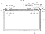
- FIG. 2 is a cross-sectional view taken along the line A-A of FIG. 1
- FIG. 3 is an exploded perspective view of the secondary battery according to an embodiment of the present invention
- FIG. 4 is a partially exploded view of a portion B of FIG. 3
- FIG. 5 is a partially exploded view of a portion C of FIG. 3 .
- the secondary battery 100 may include a case 110, an electrode assembly 120, a first insulation plate 130, a current collector plate 140, a fastening plate 150, a lower insulation member 160, a second insulation plate 170, a cap plate 180, an upper insulation member 190, a terminal plate 200 and a sub terminal plate 220.
- the case 110 may be made of a conductive metal, e.g., aluminum, an aluminium alloy, or a nickel plated steel, and may have an approximate hexahedron shape having an opening through which the electrode assembly 120 may be inserted and placed.
- the opening which is a substantially opened part of the peripheral edge of the case 110 contacting the cap plate 130.
- the interior surface of the case 110 is basically subjected to insulation treatment to prevent an electrical short circuit from occurring inside the case 110.
- an electrode of the electrode assembly may be electrically connected to the case 110 through the cap plate 180.
- the insulation treatment of the interior surface of the case 110 may also make it possible to prevent internal electrical short circuit.
- the electrode assembly 120 is formed by winding or laminating a stacked structure including a first electrode plate, a separator, and a second electrode plate, which are thin plates or layers.
- the first electrode plate may function as a positive electrode and the second electrode plate may function as a negative electrode.
- polarities of the first and second electrode plates may differ from what is described above according to the option made by one skilled in the art.
- the first electrode plate may be formed by coating a first electrode active material, such as a transition metal oxide, on a first electrode collector formed of a metal foil made of, for example, aluminium (AI), and includes a first electrode uncoated portion to which the first electrode active material is not applied.
- the first electrode uncoated portion may function as a passage for current flowing between the first electrode plate and an exterior of the first electrode plate.
- Embodiments of the present invention are not limited to the material of the first electrode plate listed herein.
- the first electrode uncoated portion may form a first electrode tab 121.
- the first electrode tab 121 includes a plurality of first electrode tabs and may be formed to protrude from the first electrode uncoated portion.
- the first electrode tab 121 has a multi-tab structure in which the plurality of first electrode tabs are formed at a predetermined position to be overlapped when the first electrode plate is wound or stacked.
- the first electrode plate may be wound in a state in which the plurality of first electrode tabs are spaced a preset distance apart from each other to then be arranged. Since the first electrode tab 121 is integrally formed with the first electrode plate and is drawn out from the wound first electrode plate, current collecting efficiency of the electrode assembly 120 can be advantageously increased.
- the first electrode tab 121 can be formed by a lead tab, which is separately formed from the first electrode plate according to the option made by one skilled in the art.
- the second electrode plate may be formed by coating a second electrode active material, such as graphite or carbon, on a second electrode collector formed of a metal foil made of, for example, copper (Cu) or nickel (Ni), and includes a second electrode uncoated portion to which the second electrode active material is not applied.
- a second electrode active material such as graphite or carbon
- a second electrode tab 122 may be formed from the second electrode uncoated portion so as to correspond to the first electrode tab 121.
- the second electrode tab 122 may also be formed by winding or laminating the second electrode plate in a state in which a plurality of second electrode tabs are spaced a preset distance apart from each other to then be arranged on the second electrode plate.
- the second electrode tab 122 can be formed by a lead tab, which is separately formed from the second electrode plate according to the option made by one skilled in the art.
- the separator may be positioned between the first electrode plate and the second electrode plate to prevent electrical short circuits and to allow movement of lithium ions.
- the separator may be made of a material selected from the group consisting of polyethylene, polypropylene, a composite film made of polypropylene and polyethylene. Embodiments of the present invention are not limited to the material of the separator listed herein.
- the electrode assembly 120 is accommodated in the case 110 with an electrolyte.
- the electrolyte may include an organic solvent, such as EC (ethylene carbonate), PC (propylene carbonate), DEC (diethyl carbonate), EMC (ethyl methyl carbonate), or DMC (dimethyl carbonate), and a lithium salt, such as LiPF 6 , or LiBF 4 .
- the electrolyte may be in a liquid, solid or gel phase.
- the first electrode tab 121 and the second electrode tab 122 are electrically connected to the current collector plate 140.
- the first insulation plate 130 is positioned between the current collector plate 140 and the electrode assembly 120.
- the first insulation plate 130 protects the electrode assembly 120 and can prevent the electrode assembly 120 from being damaged particularly when the cap plate 180 is inwardly deformed.
- first insulation plate 130 may fix the position of the electrode assembly 120 inside the case 110 and may become electrically independent of the cap plate 180.
- an additional second insulation plate 170 in addition to the first insulation plate 130 may be further formed on the current collector plate 140.
- the first insulation plate 130 includes at least one or more protrusions 131 and 132 upwardly protruding from the basic form of a plate.
- the protrusions 131 and 132 are coupled to the current collector plate 140 and the second insulation plate 170, thereby achieving an increased fastening force.
- the first insulation plate 130 may include a hole 133 positioned corresponding to a safety vent 181 of the cap plate 180. Therefore, gases generated in the case 110 may reach the safety vent 181 of the cap plate 180 through the hole 133 and the safety vent 181 may perform an inverting operation under a predetermined pressure.
- the first insulation plate 130 may be made of a material such as polyethylene or polypropylene, but embodiments of the present invention are not limited to the material of the separator listed herein.
- the current collector plate 140 is formed on the first insulation plate 130 and is connected to the first and second electrode tabs 121 and 122 of the electrode assembly 120. To this end, the current collector plate 140 may be provided in pair of a first current collector plate 141 and a second current collector plate 142.
- the first current collector plate 141 is coupled to the first electrode tab 121.
- the first electrode tab 121 protrudes from a side portion of the first insulation plate 130, it is bent to surround opposite sides of the first current collector plate 141. In such a state, the first current collector plate 141 may be coupled to the first electrode tab 121. Therefore, the first current collector plate 141 may be electrically connected to the first electrode tab 121 to have a positive polarity, for example.
- the first current collector plate 141 may be coupled to a bottom surface of the cap plate 180 at its opposite ends by welding. Therefore, the cap plate 180 and the case 110 coupled thereto may have the same polarity with the first current collector plate 141.
- the first current collector plate 141 includes coupling regions 141a and 141b formed at its opposite edges facing each other to be welded to the cap plate 180, and a plate region 141c formed between the coupling regions 141a and 141b.
- holes are formed in the coupling regions 141a and 141b to be fastened with a coupling protrusion 180b protruding to the bottom surface of the cap plate 180, the coupling protrusion 180b of the cap plate 180 and the coupling regions 141a and 141b are coupled to each other, thereby maintaining the first current collector plate 141 and the cap plate 180 to be coupled at accurate positions.
- a hole 141d for allowing internal gases of the case 110 to move is formed in a region corresponding to the safety vent 181 of the cap plate 180. Therefore, since the gases generated in the case 110 move up to the safety vent 181 along the hole 141d, the secondary battery 10 may sensitively operate with respect to the internal gases of the case 110.
- the second current collector plate 142 is formed at a region corresponding to the second electrode tab 122 of the electrode assembly 120. After the second electrode tab 122 protrudes from a side portion of the first insulation plate 130, like the first electrode tab 121, it is bent to surround opposite sides of the second current collector plate 142. In such a state, the second current collector plate 142 may be coupled to the second electrode tab 122 by, for example, welding. Therefore, the second current collector plate 142 may be coupled to the second electrode tab 122 to have a negative polarity, for example.
- the fastening plate 150 may be coupled to a top portion of the second current collector plate 142. Specifically, the fastening plate 150 may be coupled to the second current collector plate 142 by welding. Accordingly, the fastening plate 150 may have the same polarity with the second current collector plate 142. The fastening plate 150 upwardly protrudes and may be coupled to the terminal plate 200 to later be coupled to the cap plate 180.
- the lower insulation member 160 is formed between the first insulation plate 130 and the cap plate 180.
- the lower insulation member 160 is formed at a position corresponding to a region of the cap plate 180 where a terminal hole 184 is formed.
- the lower insulation member 160 surrounds the outer circumference of the fastening plate 150 to be electrically disconnected from the cap plate 180.
- the lower insulation member 160 may also be made of a material such as polyethylene or polypropylene, but embodiments of the present invention are not limited to the material of the separator listed herein.
- a separate gasket (not shown) may further be formed in the lower insulation member 160.
- the gasket may prevent an electrolyte contained in the case 110 from leaking out along with the lower insulation member 160.
- the second insulation plate 170 is formed between the second current collector plate 142 and the cap plate 180.
- the second insulation plate 170 may prevent the second current collector plate 142 from making contact with the cap plate 180, thereby preventing an electrical short circuit.
- the second insulation plate 170 is coupled to the first insulation plate 130 to fix the position of the second current collector plate 142 formed between the second insulation plate 170 and the first insulation plate 130.
- the second insulation plate 170 may include grooves or holes 171 corresponding to the protrusions 131 and 132 of the first insulation plate 130.
- the second insulation plate 170 may further include a terminal hole 172 for allowing the fastening plate 150 to penetrate. Therefore, the fastening plate 150 may protrude to penetrate the cap plate 180 to then be electrically connected to the terminal plate 200.
- the cap plate 180 may be provided in a plate shape to seal the opening of the case 110 and may be made of the same material with the case 110.
- the cap plate 130 may be coupled to the case 110 by laser welding.
- the cap plate 130 may be electrically connected to the first electrode tab 121 through the first current collector plate 141.
- the cap plate 130 and the case 110 have the same polarity, e.g., a first polarity.
- the cap plate 180 may fix positions of the first and second regions 141 a and 141 b of the first current collector plate 141 through the coupling protrusion 180b protruding to the bottom surface of the cap plate 180, and welding is performed in such a state, thereby maintaining a stable state of physical/electrical coupling.
- the safety vent 181 is formed to have a thinner region than other regions of the cap plate 130.
- the safety vent 181 is coupled to a stepped portion of a vent hole 180a formed in the cap plate 180.
- the safety vent 181 is coupled to a connector part 220a of the sub terminal plate 220 extending from a first terminal plate 201 of the terminal plate 200 at its roughly central contact region 181 a. Therefore, the cap plate 180 coupled to the first current collector plate 141 can be finally electrically connected to the terminal plate 200 through the sub terminal plate 220.
- the safety vent 181 is convexly formed roughly toward the case 110. Therefore, when the internal pressure of the case 110 is higher than a predetermined pressure, the safety vent 181 is inverted and falls off the cap plate 180 according to the inverting force.
- the safety vent 181 performs an inverting operation, an electrical connection between the cap plate 180 and the sub terminal plate 220 is cut off. Therefore, since an electrical path extending from the cap plate 180 to the sub terminal plate 220 and the first terminal plate 201 is blocked, the first terminal plate 201 becomes electrically neutral so that charging and discharging operations are stopped, thereby ensuring battery safety. In addition, since the cap plate 180 is opened by the safety vent 181 falling off the cap plate 180, the internal pressure of the case 110 can be prevented, thereby preventing the secondary battery 10 from exploding.
- the cap plate 180 in order to inject an electrolyte into at least one side of the cap plate 180, the cap plate 180 includes an inlet 182.
- the electrolyte is injected into the cap plate 180 through the inlet 182 and the inlet 182 is then sealed by an inlet plugging ball 185 and a plug 186.
- the cap plate 180 includes an uneven pattern 183 formed at its one side.
- the uneven pattern 183 is configured by a concave part 183a having a relatively small height and a convex part 183b having a relatively large height.
- the concave part 183a may be formed through a groove formed in a thickness direction of the cap plate 180, and the uneven pattern 183 may be formed by multiple concentric circles shaped by repeatedly forming the concave part 183a and the convex part 183b.
- the uneven pattern 183 is provided for increasing a fastening force with respect to a first upper insulation member 191 of the upper insulation member 190, and a protrusion 191 b formed in the first upper insulation member 191 is engaged with and coupled to the uneven pattern 183 to increase a fastened area.
- a separate adhesion member 210 is formed on a contact interface between the uneven pattern 183 of the cap plate 180 and the protrusion 191 b of the first upper insulation member 191, thereby maintaining a securely coupled state of the cap plate 180 and the first upper insulation member 191.
- the cap plate 180 includes the terminal hole 184 formed at the other side opposite to and facing one side of the cap plate 180. Therefore, a second terminal plate 202 of the terminal plate 200 may be coupled to the fastening plate 150 through the terminal hole 184. Therefore, the second terminal plate 202 coupled to the terminal hole 184 may have the same polarity with the fastening plate 150, e.g., a negative polarity.
- the upper insulation member 190 is formed at positions corresponding to the uneven pattern 183 and the terminal hole 184 of the cap plate 180.
- the upper insulation member 190 includes the first upper insulation member 191 corresponding to the uneven pattern 183 and a second upper insulation member 192 corresponding to the terminal hole 184.
- the first upper insulation member 191 positioned corresponding to the uneven pattern 183 of the cap plate 180, partitions regions of the cap plate 180 by a barrier 191 a upwardly protruding from edges of the first upper insulation member 191 and accommodates the first terminal plate 201 within the barrier 191 a. Therefore, the first upper insulation member 191 may allow the first terminal plate 201 to become electrically independent of the cap plate 180.
- the first upper insulation member 191 may include the protrusion or groove 191 b protruding upward or downward.
- the protrusion or groove 191 b of the first upper insulation member 191 is formed by concentric circles corresponding to those of the uneven pattern 183 of the underlying cap plate 180 to then be coupled to the uneven pattern 183.
- the protrusion or groove 191 b is coupled to the overlying first terminal plate 201 in the same manner as described above.
- the adhesion member 210 is formed on contact interfaces between the first upper insulation member 191 and the uneven pattern 183 of the cap plate 180 and between the first terminal plate 201 and the uneven pattern 183 of the cap plate 180 and physically coupled states can be maintained.
- the second upper insulation member 192 is formed at a region corresponding to the terminal hole 184 of the cap plate 180 and accommodates the second terminal plate 202 of the terminal plate 200 in its inside region.
- the second upper insulation member 192 allows the second terminal plate 202 to be coupled to the fastening plate 150 through a terminal hole 192a formed therein, thereby electrically connecting the second terminal plate 202 to the fastening plate 150.
- the terminal plate 200 may be provided in a pair and may include the first terminal plate 201 corresponding to the uneven pattern 183 of the cap plate 180 and a second terminal plate 202 corresponding to the terminal hole 184.
- the first terminal plate 201 is coupled to a top portion of the first upper insulation member 191.
- a protrusion or groove 201 b downwardly protruding from the first terminal plate 201 is formed to be engaged with the protrusion or groove 191 b of the first upper insulation member 191. Therefore, the protrusion or groove 201 b of the first terminal plate 201 is engaged with and coupled to the protrusion or groove 191 b of the first upper insulation member 191, thereby increasing a fastened area.
- the adhesion member 210 is further formed on the contact interface between the first terminal plate 201 and the first upper insulation member 191, a securely coupled state between the first terminal plate 201 and the first upper insulation member 191 can be maintained. Therefore, the first terminal plate 201 is not in direct contact with the cap plate 180 by the first upper insulation member 191 but is maintained in a state in which it is electrically connected with the safety vent 181 of the cap plate 180 through the sub terminal plate 220.
- the first terminal plate 201 is coupled to the sub terminal plate 220 through a groove 201 a formed at one side of the top portion of the first terminal plate 201.
- the groove 201 a may be formed to have a height corresponding to a thickness of the sub terminal plate 220, and the first terminal plate 201 may be physically/electrically connected to the sub terminal plate 220 by performing welding on a contact region of the groove 201a.
- the second terminal plate 202 is connected to the fastening plate 150 exposed through the cap plate 180. Therefore, the second terminal plate 202 may have the same polarity with the fastening plate 150, e.g., a negative polarity. In this case, since the lower insulation member 160 and the second upper insulation member 192 are positioned between the second terminal plate 202 and the cap plate 180 and between the fastening plate 150 and the cap plate 180, electrical short circuits can be prevented.
- the adhesion member 210 may be formed at top and bottom regions where the first upper insulation member 191 is coupled to the uneven pattern 183 of the cap plate 180 and the first terminal plate 201 to have elements 210a and 210b. In addition, some spaces where the adhesion member 210 is to be formed may be provided on contact interfaces coupled to the elements 210a and 210b. Therefore, even if the first upper insulation member 191 is coupled to the uneven pattern 183 of the cap plate 180 and the first terminal plate 201 with the adhesion member 210 interposed therebetween, the adhesion member 210 may be accommodated within the spaces without being exposed to the outside.
- the adhesion member 210 may include a general adhesive paste and may be provided in the form of an adhesive tape according to the option made by one skilled in the art.
- the first upper insulation member 191 can be maintained in a stably fasted state by the adhesion member 210 even without separate fastening members with respect to the uneven pattern 183 of the cap plate 180 and the first terminal plate 201.
- a welding process is not required in sequentially coupling the cap plate 180, the first upper insulation member 191 and the first terminal plate 201, thereby simplifying the configuration of electrode terminals and reducing the manufacturing process and cost.
- the sub terminal plate 220 is formed between the first terminal plate 201 and the first upper insulation member 191.
- the sub terminal plate 220 is in contact with the first terminal plate 201 to then be electrically connected.
- the sub terminal plate 220 includes connector parts 220a and 220b protruding toward the safety vent 181 of the cap plate 180.
- the connector parts 220a and 220b are integrally formed with an end 220c at which the sub terminal plate 220 is coupled to the first terminal plate 201, thereby obviating the need for separate components or a coupling process, such as welding.
- the sub terminal plate 220 including the connector parts 220a and 220b is coupled to the first terminal plate 201, operating reliability of the connector parts 220a and 220b can be increased.
- the connector parts 220a and 220b are fixed to the safety vent 181 by welding. In addition, the connector parts 220a and 220b maintain a state in which a predetermined level of elastic restoring force is applied thereto.
- the connector parts 220a and 220b includes a contact region 220a fixed to the contact region 181a of the safety vent 181, and an extension region 220b where elastic restoring force is applied to the contact region 220a.
- the contact region 220a may be coupled to the contact region 181a of the safety vent 181 by welding.
- the extension region 220b is formed in a bent shape to have elastic restoring force and is maintained in a state in which it is fixed by the welding of the contact region 220a. Therefore, as will later be described, if the safety vent 181 is inverted to be separated from the cap plate 180, the safety vent 181 is lifted by the force applied from the extension region 220b, thereby cutting off an electrical connection.
- FIG. 6 is a partially exploded view illustrating a state in which a safety vent is opened in the secondary battery according to an embodiment of the present invention.
- the safety vent 181 when the internal pressure of the case 110 is higher than a predetermined pressure, the safety vent 181 performs an inverting operation. In addition, as the result of the inverting operation, edges of the safety vent 181 are ruptured from the cap plate 180. Here, the safety vent 181 coupled to the contact region 220a is lifted by the elastic restoring force of the extension region 220b as one of the connector parts 220a and 220b of the terminal plate 220. In addition, since the safety vent 181 is continuously maintained in the opened state, it is possible to prevent the secondary battery 10 from exploding even if the internal pressure of the case 110 is increased.
Landscapes
- Chemical & Material Sciences (AREA)
- Chemical Kinetics & Catalysis (AREA)
- Electrochemistry (AREA)
- General Chemical & Material Sciences (AREA)
- Engineering & Computer Science (AREA)
- Manufacturing & Machinery (AREA)
- Connection Of Batteries Or Terminals (AREA)
- Gas Exhaust Devices For Batteries (AREA)
Applications Claiming Priority (1)
| Application Number | Priority Date | Filing Date | Title |
|---|---|---|---|
| KR20160138252 | 2016-10-24 |
Publications (2)
| Publication Number | Publication Date |
|---|---|
| EP3312901A1 true EP3312901A1 (de) | 2018-04-25 |
| EP3312901B1 EP3312901B1 (de) | 2020-04-29 |
Family
ID=60037438
Family Applications (1)
| Application Number | Title | Priority Date | Filing Date |
|---|---|---|---|
| EP17195098.3A Active EP3312901B1 (de) | 2016-10-24 | 2017-10-06 | Sekundärbatterie |
Country Status (4)
| Country | Link |
|---|---|
| US (1) | US10547030B2 (de) |
| EP (1) | EP3312901B1 (de) |
| KR (1) | KR102422513B1 (de) |
| CN (1) | CN107978699B (de) |
Cited By (1)
| Publication number | Priority date | Publication date | Assignee | Title |
|---|---|---|---|---|
| SE2250960A1 (en) * | 2022-08-12 | 2024-02-13 | Northvolt Ab | Battery cell with spacing element |
Families Citing this family (13)
| Publication number | Priority date | Publication date | Assignee | Title |
|---|---|---|---|---|
| CN111106304B9 (zh) * | 2018-10-30 | 2021-06-11 | 宁德时代新能源科技股份有限公司 | 二次电池 |
| CN208955087U (zh) * | 2018-10-30 | 2019-06-07 | 宁德时代新能源科技股份有限公司 | 二次电池 |
| KR102799930B1 (ko) * | 2019-07-18 | 2025-04-28 | 삼성에스디아이 주식회사 | 이물 유입 방지 구조를 갖는 이차 전지 |
| CN114865245B (zh) * | 2019-11-25 | 2024-01-02 | 宁德时代新能源科技股份有限公司 | 电池单体、电池模块、电池组、使用电池单体作为电源的装置及电池单体的组装方法 |
| CN111244340B (zh) * | 2020-03-10 | 2025-04-04 | 江苏正力新能电池技术股份有限公司 | 一种电池顶盖结构及装配方法 |
| TWI900540B (zh) | 2020-03-11 | 2025-10-11 | 南韓商Lg新能源股份有限公司 | 鈕扣型二次電池 |
| CN214542378U (zh) * | 2021-03-24 | 2021-10-29 | 宁德新能源科技有限公司 | 电池单元与馈通组件 |
| KR20230083644A (ko) | 2021-12-03 | 2023-06-12 | 삼성에스디아이 주식회사 | 이차 전지 |
| CN218769817U (zh) * | 2022-07-15 | 2023-03-28 | 宁德时代新能源科技股份有限公司 | 电池单体、电池及用电设备 |
| WO2024016275A1 (zh) * | 2022-07-21 | 2024-01-25 | 宁德时代新能源科技股份有限公司 | 电池单体、电池及用电设备 |
| CN118435432A (zh) * | 2022-08-29 | 2024-08-02 | 宁德时代新能源科技股份有限公司 | 顶盖组件、电池单体、电池及用电装置 |
| CN115579591B (zh) * | 2022-11-14 | 2023-03-21 | 深圳海润新能源科技有限公司 | 盖板组件、电池、电池的组装方法、电池包以及用电设备 |
| CN117080638B (zh) * | 2023-10-12 | 2023-12-26 | 厦门海辰储能科技股份有限公司 | 端盖组件、储能装置和用电设备 |
Citations (3)
| Publication number | Priority date | Publication date | Assignee | Title |
|---|---|---|---|---|
| US6403250B1 (en) * | 1999-03-01 | 2002-06-11 | Alps Electric Co., Ltd. | Pressure sensitive current breaker for a cell |
| US20110183167A1 (en) * | 2010-01-27 | 2011-07-28 | Jongseok Moon | Secondary battery |
| US20150295221A1 (en) * | 2012-11-26 | 2015-10-15 | Hitachi Automotive Systems, Ltd. | Rectangular secondary battery |
Family Cites Families (10)
| Publication number | Priority date | Publication date | Assignee | Title |
|---|---|---|---|---|
| JP3616259B2 (ja) | 1998-09-10 | 2005-02-02 | アルプス電気株式会社 | 電池 |
| KR101056426B1 (ko) * | 2009-06-23 | 2011-08-11 | 에스비리모티브 주식회사 | 이차전지 및 그 모듈 |
| US9246140B2 (en) | 2009-07-09 | 2016-01-26 | Samsung Sdi Co., Ltd. | Rechargeable battery with a cap assembly having a first tab located outside of the case |
| DE102013204319A1 (de) * | 2013-03-13 | 2014-09-18 | Robert Bosch Gmbh | Sicherheitsvorrichtung für eine galvanische Zelle |
| US20140302361A1 (en) * | 2013-04-08 | 2014-10-09 | Samsung Sdi Co., Ltd. | Rechargeable battery |
| US9515297B2 (en) * | 2013-07-19 | 2016-12-06 | Samsung Sdi Co., Ltd. | Rechargeable battery |
| KR101617367B1 (ko) | 2014-04-01 | 2016-05-03 | 주식회사 엘엠에스 | 보조집광부를 구비한 광학시트 모듈 |
| KR101606547B1 (ko) | 2014-06-02 | 2016-03-28 | 김동연 | 공항 탑승객 위치조회시스템 |
| US10008710B2 (en) * | 2014-08-04 | 2018-06-26 | Johnson Controls Technology Company | Overcharge protection assembly for a battery module |
| KR102308631B1 (ko) | 2014-08-13 | 2021-10-05 | 삼성에스디아이 주식회사 | 이차 전지 및 그 제조방법 |
-
2017
- 2017-07-14 KR KR1020170089644A patent/KR102422513B1/ko active Active
- 2017-09-28 US US15/719,373 patent/US10547030B2/en active Active
- 2017-09-29 CN CN201710905740.3A patent/CN107978699B/zh active Active
- 2017-10-06 EP EP17195098.3A patent/EP3312901B1/de active Active
Patent Citations (3)
| Publication number | Priority date | Publication date | Assignee | Title |
|---|---|---|---|---|
| US6403250B1 (en) * | 1999-03-01 | 2002-06-11 | Alps Electric Co., Ltd. | Pressure sensitive current breaker for a cell |
| US20110183167A1 (en) * | 2010-01-27 | 2011-07-28 | Jongseok Moon | Secondary battery |
| US20150295221A1 (en) * | 2012-11-26 | 2015-10-15 | Hitachi Automotive Systems, Ltd. | Rectangular secondary battery |
Cited By (1)
| Publication number | Priority date | Publication date | Assignee | Title |
|---|---|---|---|---|
| SE2250960A1 (en) * | 2022-08-12 | 2024-02-13 | Northvolt Ab | Battery cell with spacing element |
Also Published As
| Publication number | Publication date |
|---|---|
| CN107978699A (zh) | 2018-05-01 |
| US20180114954A1 (en) | 2018-04-26 |
| KR102422513B1 (ko) | 2022-07-20 |
| US10547030B2 (en) | 2020-01-28 |
| KR20180044795A (ko) | 2018-05-03 |
| CN107978699B (zh) | 2020-12-22 |
| EP3312901B1 (de) | 2020-04-29 |
Similar Documents
| Publication | Publication Date | Title |
|---|---|---|
| EP3312901B1 (de) | Sekundärbatterie | |
| CN109428045B (zh) | 二次电池及其组装方法 | |
| US10109838B2 (en) | Rechargeable battery and manufacturing method thereof | |
| EP2495784B1 (de) | Sekundärbatterie | |
| US11600845B2 (en) | Secondary battery | |
| EP4376148A2 (de) | Sekundärbatterie | |
| CN109428046B (zh) | 二次电池 | |
| EP4439748A1 (de) | Sekundärbatterie | |
| KR20160134236A (ko) | 이차 전지 | |
| EP3046158A1 (de) | Wiederaufladbare batterie und packung dafür | |
| CN106684267B (zh) | 可再充电电池 | |
| US10998534B2 (en) | Secondary battery | |
| EP2899779B1 (de) | Sekundärbatterie | |
| US11258140B2 (en) | Secondary battery | |
| US12573696B2 (en) | Secondary battery | |
| KR100846955B1 (ko) | 원통형 이차전지 | |
| KR102337491B1 (ko) | 이차 전지 | |
| EP4210156A1 (de) | Sekundärbatterie | |
| EP4451431A1 (de) | Sekundärbatterie | |
| EP2477250B1 (de) | Wiederaufladbare batterie | |
| EP3712978A1 (de) | Sekundärbatterie | |
| EP3518313A1 (de) | Sekundärbatterie | |
| US10211446B2 (en) | Rechargeable battery | |
| US20260074399A1 (en) | Secondary battery |
Legal Events
| Date | Code | Title | Description |
|---|---|---|---|
| PUAI | Public reference made under article 153(3) epc to a published international application that has entered the european phase |
Free format text: ORIGINAL CODE: 0009012 |
|
| STAA | Information on the status of an ep patent application or granted ep patent |
Free format text: STATUS: REQUEST FOR EXAMINATION WAS MADE |
|
| 17P | Request for examination filed |
Effective date: 20171006 |
|
| AK | Designated contracting states |
Kind code of ref document: A1 Designated state(s): AL AT BE BG CH CY CZ DE DK EE ES FI FR GB GR HR HU IE IS IT LI LT LU LV MC MK MT NL NO PL PT RO RS SE SI SK SM TR |
|
| AX | Request for extension of the european patent |
Extension state: BA ME |
|
| GRAP | Despatch of communication of intention to grant a patent |
Free format text: ORIGINAL CODE: EPIDOSNIGR1 |
|
| STAA | Information on the status of an ep patent application or granted ep patent |
Free format text: STATUS: GRANT OF PATENT IS INTENDED |
|
| INTG | Intention to grant announced |
Effective date: 20200109 |
|
| RIC1 | Information provided on ipc code assigned before grant |
Ipc: H01M 2/12 20060101ALI20191216BHEP Ipc: H01M 2/30 20060101ALI20191216BHEP Ipc: H01M 2/04 20060101ALI20191216BHEP Ipc: H01M 2/02 20060101AFI20191216BHEP Ipc: H01M 2/34 20060101ALI20191216BHEP |
|
| GRAS | Grant fee paid |
Free format text: ORIGINAL CODE: EPIDOSNIGR3 |
|
| GRAA | (expected) grant |
Free format text: ORIGINAL CODE: 0009210 |
|
| STAA | Information on the status of an ep patent application or granted ep patent |
Free format text: STATUS: THE PATENT HAS BEEN GRANTED |
|
| AK | Designated contracting states |
Kind code of ref document: B1 Designated state(s): AL AT BE BG CH CY CZ DE DK EE ES FI FR GB GR HR HU IE IS IT LI LT LU LV MC MK MT NL NO PL PT RO RS SE SI SK SM TR |
|
| REG | Reference to a national code |
Ref country code: GB Ref legal event code: FG4D |
|
| REG | Reference to a national code |
Ref country code: CH Ref legal event code: EP |
|
| REG | Reference to a national code |
Ref country code: AT Ref legal event code: REF Ref document number: 1264629 Country of ref document: AT Kind code of ref document: T Effective date: 20200515 |
|
| REG | Reference to a national code |
Ref country code: DE Ref legal event code: R096 Ref document number: 602017015581 Country of ref document: DE |
|
| REG | Reference to a national code |
Ref country code: IE Ref legal event code: FG4D |
|
| REG | Reference to a national code |
Ref country code: NL Ref legal event code: MP Effective date: 20200429 |
|
| REG | Reference to a national code |
Ref country code: LT Ref legal event code: MG4D |
|
| PG25 | Lapsed in a contracting state [announced via postgrant information from national office to epo] |
Ref country code: FI Free format text: LAPSE BECAUSE OF FAILURE TO SUBMIT A TRANSLATION OF THE DESCRIPTION OR TO PAY THE FEE WITHIN THE PRESCRIBED TIME-LIMIT Effective date: 20200429 Ref country code: NO Free format text: LAPSE BECAUSE OF FAILURE TO SUBMIT A TRANSLATION OF THE DESCRIPTION OR TO PAY THE FEE WITHIN THE PRESCRIBED TIME-LIMIT Effective date: 20200729 Ref country code: IS Free format text: LAPSE BECAUSE OF FAILURE TO SUBMIT A TRANSLATION OF THE DESCRIPTION OR TO PAY THE FEE WITHIN THE PRESCRIBED TIME-LIMIT Effective date: 20200829 Ref country code: PT Free format text: LAPSE BECAUSE OF FAILURE TO SUBMIT A TRANSLATION OF THE DESCRIPTION OR TO PAY THE FEE WITHIN THE PRESCRIBED TIME-LIMIT Effective date: 20200831 Ref country code: SE Free format text: LAPSE BECAUSE OF FAILURE TO SUBMIT A TRANSLATION OF THE DESCRIPTION OR TO PAY THE FEE WITHIN THE PRESCRIBED TIME-LIMIT Effective date: 20200429 Ref country code: GR Free format text: LAPSE BECAUSE OF FAILURE TO SUBMIT A TRANSLATION OF THE DESCRIPTION OR TO PAY THE FEE WITHIN THE PRESCRIBED TIME-LIMIT Effective date: 20200730 Ref country code: LT Free format text: LAPSE BECAUSE OF FAILURE TO SUBMIT A TRANSLATION OF THE DESCRIPTION OR TO PAY THE FEE WITHIN THE PRESCRIBED TIME-LIMIT Effective date: 20200429 |
|
| REG | Reference to a national code |
Ref country code: AT Ref legal event code: MK05 Ref document number: 1264629 Country of ref document: AT Kind code of ref document: T Effective date: 20200429 |
|
| REG | Reference to a national code |
Ref country code: DE Ref legal event code: R079 Ref document number: 602017015581 Country of ref document: DE Free format text: PREVIOUS MAIN CLASS: H01M0002020000 Ipc: H01M0050100000 |
|
| PG25 | Lapsed in a contracting state [announced via postgrant information from national office to epo] |
Ref country code: RS Free format text: LAPSE BECAUSE OF FAILURE TO SUBMIT A TRANSLATION OF THE DESCRIPTION OR TO PAY THE FEE WITHIN THE PRESCRIBED TIME-LIMIT Effective date: 20200429 Ref country code: HR Free format text: LAPSE BECAUSE OF FAILURE TO SUBMIT A TRANSLATION OF THE DESCRIPTION OR TO PAY THE FEE WITHIN THE PRESCRIBED TIME-LIMIT Effective date: 20200429 Ref country code: LV Free format text: LAPSE BECAUSE OF FAILURE TO SUBMIT A TRANSLATION OF THE DESCRIPTION OR TO PAY THE FEE WITHIN THE PRESCRIBED TIME-LIMIT Effective date: 20200429 Ref country code: BG Free format text: LAPSE BECAUSE OF FAILURE TO SUBMIT A TRANSLATION OF THE DESCRIPTION OR TO PAY THE FEE WITHIN THE PRESCRIBED TIME-LIMIT Effective date: 20200729 |
|
| PG25 | Lapsed in a contracting state [announced via postgrant information from national office to epo] |
Ref country code: NL Free format text: LAPSE BECAUSE OF FAILURE TO SUBMIT A TRANSLATION OF THE DESCRIPTION OR TO PAY THE FEE WITHIN THE PRESCRIBED TIME-LIMIT Effective date: 20200429 Ref country code: AL Free format text: LAPSE BECAUSE OF FAILURE TO SUBMIT A TRANSLATION OF THE DESCRIPTION OR TO PAY THE FEE WITHIN THE PRESCRIBED TIME-LIMIT Effective date: 20200429 |
|
| PG25 | Lapsed in a contracting state [announced via postgrant information from national office to epo] |
Ref country code: AT Free format text: LAPSE BECAUSE OF FAILURE TO SUBMIT A TRANSLATION OF THE DESCRIPTION OR TO PAY THE FEE WITHIN THE PRESCRIBED TIME-LIMIT Effective date: 20200429 Ref country code: DK Free format text: LAPSE BECAUSE OF FAILURE TO SUBMIT A TRANSLATION OF THE DESCRIPTION OR TO PAY THE FEE WITHIN THE PRESCRIBED TIME-LIMIT Effective date: 20200429 Ref country code: IT Free format text: LAPSE BECAUSE OF FAILURE TO SUBMIT A TRANSLATION OF THE DESCRIPTION OR TO PAY THE FEE WITHIN THE PRESCRIBED TIME-LIMIT Effective date: 20200429 Ref country code: EE Free format text: LAPSE BECAUSE OF FAILURE TO SUBMIT A TRANSLATION OF THE DESCRIPTION OR TO PAY THE FEE WITHIN THE PRESCRIBED TIME-LIMIT Effective date: 20200429 Ref country code: SM Free format text: LAPSE BECAUSE OF FAILURE TO SUBMIT A TRANSLATION OF THE DESCRIPTION OR TO PAY THE FEE WITHIN THE PRESCRIBED TIME-LIMIT Effective date: 20200429 Ref country code: CZ Free format text: LAPSE BECAUSE OF FAILURE TO SUBMIT A TRANSLATION OF THE DESCRIPTION OR TO PAY THE FEE WITHIN THE PRESCRIBED TIME-LIMIT Effective date: 20200429 Ref country code: RO Free format text: LAPSE BECAUSE OF FAILURE TO SUBMIT A TRANSLATION OF THE DESCRIPTION OR TO PAY THE FEE WITHIN THE PRESCRIBED TIME-LIMIT Effective date: 20200429 Ref country code: ES Free format text: LAPSE BECAUSE OF FAILURE TO SUBMIT A TRANSLATION OF THE DESCRIPTION OR TO PAY THE FEE WITHIN THE PRESCRIBED TIME-LIMIT Effective date: 20200429 |
|
| REG | Reference to a national code |
Ref country code: DE Ref legal event code: R097 Ref document number: 602017015581 Country of ref document: DE |
|
| PG25 | Lapsed in a contracting state [announced via postgrant information from national office to epo] |
Ref country code: PL Free format text: LAPSE BECAUSE OF FAILURE TO SUBMIT A TRANSLATION OF THE DESCRIPTION OR TO PAY THE FEE WITHIN THE PRESCRIBED TIME-LIMIT Effective date: 20200429 Ref country code: SK Free format text: LAPSE BECAUSE OF FAILURE TO SUBMIT A TRANSLATION OF THE DESCRIPTION OR TO PAY THE FEE WITHIN THE PRESCRIBED TIME-LIMIT Effective date: 20200429 |
|
| PLBE | No opposition filed within time limit |
Free format text: ORIGINAL CODE: 0009261 |
|
| STAA | Information on the status of an ep patent application or granted ep patent |
Free format text: STATUS: NO OPPOSITION FILED WITHIN TIME LIMIT |
|
| 26N | No opposition filed |
Effective date: 20210201 |
|
| PG25 | Lapsed in a contracting state [announced via postgrant information from national office to epo] |
Ref country code: SI Free format text: LAPSE BECAUSE OF FAILURE TO SUBMIT A TRANSLATION OF THE DESCRIPTION OR TO PAY THE FEE WITHIN THE PRESCRIBED TIME-LIMIT Effective date: 20200429 |
|
| REG | Reference to a national code |
Ref country code: CH Ref legal event code: PL |
|
| PG25 | Lapsed in a contracting state [announced via postgrant information from national office to epo] |
Ref country code: MC Free format text: LAPSE BECAUSE OF FAILURE TO SUBMIT A TRANSLATION OF THE DESCRIPTION OR TO PAY THE FEE WITHIN THE PRESCRIBED TIME-LIMIT Effective date: 20200429 Ref country code: LU Free format text: LAPSE BECAUSE OF NON-PAYMENT OF DUE FEES Effective date: 20201006 |
|
| REG | Reference to a national code |
Ref country code: BE Ref legal event code: MM Effective date: 20201031 |
|
| PG25 | Lapsed in a contracting state [announced via postgrant information from national office to epo] |
Ref country code: CH Free format text: LAPSE BECAUSE OF NON-PAYMENT OF DUE FEES Effective date: 20201031 Ref country code: BE Free format text: LAPSE BECAUSE OF NON-PAYMENT OF DUE FEES Effective date: 20201031 Ref country code: LI Free format text: LAPSE BECAUSE OF NON-PAYMENT OF DUE FEES Effective date: 20201031 |
|
| PG25 | Lapsed in a contracting state [announced via postgrant information from national office to epo] |
Ref country code: IE Free format text: LAPSE BECAUSE OF NON-PAYMENT OF DUE FEES Effective date: 20201006 |
|
| PG25 | Lapsed in a contracting state [announced via postgrant information from national office to epo] |
Ref country code: TR Free format text: LAPSE BECAUSE OF FAILURE TO SUBMIT A TRANSLATION OF THE DESCRIPTION OR TO PAY THE FEE WITHIN THE PRESCRIBED TIME-LIMIT Effective date: 20200429 Ref country code: MT Free format text: LAPSE BECAUSE OF FAILURE TO SUBMIT A TRANSLATION OF THE DESCRIPTION OR TO PAY THE FEE WITHIN THE PRESCRIBED TIME-LIMIT Effective date: 20200429 Ref country code: CY Free format text: LAPSE BECAUSE OF FAILURE TO SUBMIT A TRANSLATION OF THE DESCRIPTION OR TO PAY THE FEE WITHIN THE PRESCRIBED TIME-LIMIT Effective date: 20200429 |
|
| PG25 | Lapsed in a contracting state [announced via postgrant information from national office to epo] |
Ref country code: MK Free format text: LAPSE BECAUSE OF FAILURE TO SUBMIT A TRANSLATION OF THE DESCRIPTION OR TO PAY THE FEE WITHIN THE PRESCRIBED TIME-LIMIT Effective date: 20200429 |
|
| P01 | Opt-out of the competence of the unified patent court (upc) registered |
Effective date: 20230528 |
|
| PGFP | Annual fee paid to national office [announced via postgrant information from national office to epo] |
Ref country code: FR Payment date: 20250930 Year of fee payment: 9 |
|
| PGFP | Annual fee paid to national office [announced via postgrant information from national office to epo] |
Ref country code: DE Payment date: 20250930 Year of fee payment: 9 |
|
| PGFP | Annual fee paid to national office [announced via postgrant information from national office to epo] |
Ref country code: GB Payment date: 20251001 Year of fee payment: 9 |