EP4439748A1 - Sekundärbatterie - Google Patents
Sekundärbatterie Download PDFInfo
- Publication number
- EP4439748A1 EP4439748A1 EP23206856.9A EP23206856A EP4439748A1 EP 4439748 A1 EP4439748 A1 EP 4439748A1 EP 23206856 A EP23206856 A EP 23206856A EP 4439748 A1 EP4439748 A1 EP 4439748A1
- Authority
- EP
- European Patent Office
- Prior art keywords
- cap plate
- secondary battery
- electrode assembly
- welding portion
- plate
- Prior art date
- Legal status (The legal status is an assumption and is not a legal conclusion. Google has not performed a legal analysis and makes no representation as to the accuracy of the status listed.)
- Pending
Links
Images


Classifications
-
- H—ELECTRICITY
- H01—ELECTRIC ELEMENTS
- H01M—PROCESSES OR MEANS, e.g. BATTERIES, FOR THE DIRECT CONVERSION OF CHEMICAL ENERGY INTO ELECTRICAL ENERGY
- H01M50/00—Constructional details or processes of manufacture of the non-active parts of electrochemical cells other than fuel cells, e.g. hybrid cells
- H01M50/50—Current conducting connections for cells or batteries
- H01M50/543—Terminals
- H01M50/545—Terminals formed by the casing of the cells
-
- H—ELECTRICITY
- H01—ELECTRIC ELEMENTS
- H01M—PROCESSES OR MEANS, e.g. BATTERIES, FOR THE DIRECT CONVERSION OF CHEMICAL ENERGY INTO ELECTRICAL ENERGY
- H01M10/00—Secondary cells; Manufacture thereof
- H01M10/04—Construction or manufacture in general
- H01M10/0431—Cells with wound or folded electrodes
-
- H—ELECTRICITY
- H01—ELECTRIC ELEMENTS
- H01M—PROCESSES OR MEANS, e.g. BATTERIES, FOR THE DIRECT CONVERSION OF CHEMICAL ENERGY INTO ELECTRICAL ENERGY
- H01M10/00—Secondary cells; Manufacture thereof
- H01M10/05—Accumulators with non-aqueous electrolyte
- H01M10/052—Li-accumulators
- H01M10/0525—Rocking-chair batteries, i.e. batteries with lithium insertion or intercalation in both electrodes; Lithium-ion batteries
-
- H—ELECTRICITY
- H01—ELECTRIC ELEMENTS
- H01M—PROCESSES OR MEANS, e.g. BATTERIES, FOR THE DIRECT CONVERSION OF CHEMICAL ENERGY INTO ELECTRICAL ENERGY
- H01M10/00—Secondary cells; Manufacture thereof
- H01M10/05—Accumulators with non-aqueous electrolyte
- H01M10/058—Construction or manufacture
- H01M10/0587—Construction or manufacture of accumulators having only wound construction elements, i.e. wound positive electrodes, wound negative electrodes and wound separators
-
- H—ELECTRICITY
- H01—ELECTRIC ELEMENTS
- H01M—PROCESSES OR MEANS, e.g. BATTERIES, FOR THE DIRECT CONVERSION OF CHEMICAL ENERGY INTO ELECTRICAL ENERGY
- H01M50/00—Constructional details or processes of manufacture of the non-active parts of electrochemical cells other than fuel cells, e.g. hybrid cells
- H01M50/10—Primary casings; Jackets or wrappings
- H01M50/102—Primary casings; Jackets or wrappings characterised by their shape or physical structure
- H01M50/107—Primary casings; Jackets or wrappings characterised by their shape or physical structure having curved cross-section, e.g. round or elliptic
-
- H—ELECTRICITY
- H01—ELECTRIC ELEMENTS
- H01M—PROCESSES OR MEANS, e.g. BATTERIES, FOR THE DIRECT CONVERSION OF CHEMICAL ENERGY INTO ELECTRICAL ENERGY
- H01M50/00—Constructional details or processes of manufacture of the non-active parts of electrochemical cells other than fuel cells, e.g. hybrid cells
- H01M50/10—Primary casings; Jackets or wrappings
- H01M50/147—Lids or covers
- H01M50/148—Lids or covers characterised by their shape
- H01M50/152—Lids or covers characterised by their shape for cells having curved cross-section, e.g. round or elliptic
-
- H—ELECTRICITY
- H01—ELECTRIC ELEMENTS
- H01M—PROCESSES OR MEANS, e.g. BATTERIES, FOR THE DIRECT CONVERSION OF CHEMICAL ENERGY INTO ELECTRICAL ENERGY
- H01M50/00—Constructional details or processes of manufacture of the non-active parts of electrochemical cells other than fuel cells, e.g. hybrid cells
- H01M50/10—Primary casings; Jackets or wrappings
- H01M50/147—Lids or covers
- H01M50/166—Lids or covers characterised by the methods of assembling casings with lids
- H01M50/169—Lids or covers characterised by the methods of assembling casings with lids by welding, brazing or soldering
-
- H—ELECTRICITY
- H01—ELECTRIC ELEMENTS
- H01M—PROCESSES OR MEANS, e.g. BATTERIES, FOR THE DIRECT CONVERSION OF CHEMICAL ENERGY INTO ELECTRICAL ENERGY
- H01M50/00—Constructional details or processes of manufacture of the non-active parts of electrochemical cells other than fuel cells, e.g. hybrid cells
- H01M50/10—Primary casings; Jackets or wrappings
- H01M50/147—Lids or covers
- H01M50/166—Lids or covers characterised by the methods of assembling casings with lids
- H01M50/171—Lids or covers characterised by the methods of assembling casings with lids using adhesives or sealing agents
-
- H—ELECTRICITY
- H01—ELECTRIC ELEMENTS
- H01M—PROCESSES OR MEANS, e.g. BATTERIES, FOR THE DIRECT CONVERSION OF CHEMICAL ENERGY INTO ELECTRICAL ENERGY
- H01M50/00—Constructional details or processes of manufacture of the non-active parts of electrochemical cells other than fuel cells, e.g. hybrid cells
- H01M50/10—Primary casings; Jackets or wrappings
- H01M50/172—Arrangements of electric connectors penetrating the casing
- H01M50/174—Arrangements of electric connectors penetrating the casing adapted for the shape of the cells
- H01M50/179—Arrangements of electric connectors penetrating the casing adapted for the shape of the cells for cells having curved cross-section, e.g. round or elliptic
-
- H—ELECTRICITY
- H01—ELECTRIC ELEMENTS
- H01M—PROCESSES OR MEANS, e.g. BATTERIES, FOR THE DIRECT CONVERSION OF CHEMICAL ENERGY INTO ELECTRICAL ENERGY
- H01M50/00—Constructional details or processes of manufacture of the non-active parts of electrochemical cells other than fuel cells, e.g. hybrid cells
- H01M50/30—Arrangements for facilitating escape of gases
- H01M50/342—Non-re-sealable arrangements
- H01M50/3425—Non-re-sealable arrangements in the form of rupturable membranes or weakened parts, e.g. pierced with the aid of a sharp member
-
- H—ELECTRICITY
- H01—ELECTRIC ELEMENTS
- H01M—PROCESSES OR MEANS, e.g. BATTERIES, FOR THE DIRECT CONVERSION OF CHEMICAL ENERGY INTO ELECTRICAL ENERGY
- H01M50/00—Constructional details or processes of manufacture of the non-active parts of electrochemical cells other than fuel cells, e.g. hybrid cells
- H01M50/50—Current conducting connections for cells or batteries
- H01M50/502—Interconnectors for connecting terminals of adjacent batteries; Interconnectors for connecting cells outside a battery casing
- H01M50/514—Methods for interconnecting adjacent batteries or cells
- H01M50/516—Methods for interconnecting adjacent batteries or cells by welding, soldering or brazing
-
- H—ELECTRICITY
- H01—ELECTRIC ELEMENTS
- H01M—PROCESSES OR MEANS, e.g. BATTERIES, FOR THE DIRECT CONVERSION OF CHEMICAL ENERGY INTO ELECTRICAL ENERGY
- H01M50/00—Constructional details or processes of manufacture of the non-active parts of electrochemical cells other than fuel cells, e.g. hybrid cells
- H01M50/50—Current conducting connections for cells or batteries
- H01M50/528—Fixed electrical connections, i.e. not intended for disconnection
-
- H—ELECTRICITY
- H01—ELECTRIC ELEMENTS
- H01M—PROCESSES OR MEANS, e.g. BATTERIES, FOR THE DIRECT CONVERSION OF CHEMICAL ENERGY INTO ELECTRICAL ENERGY
- H01M50/00—Constructional details or processes of manufacture of the non-active parts of electrochemical cells other than fuel cells, e.g. hybrid cells
- H01M50/50—Current conducting connections for cells or batteries
- H01M50/531—Electrode connections inside a battery casing
- H01M50/536—Electrode connections inside a battery casing characterised by the method of fixing the leads to the electrodes, e.g. by welding
-
- H—ELECTRICITY
- H01—ELECTRIC ELEMENTS
- H01M—PROCESSES OR MEANS, e.g. BATTERIES, FOR THE DIRECT CONVERSION OF CHEMICAL ENERGY INTO ELECTRICAL ENERGY
- H01M50/00—Constructional details or processes of manufacture of the non-active parts of electrochemical cells other than fuel cells, e.g. hybrid cells
- H01M50/50—Current conducting connections for cells or batteries
- H01M50/543—Terminals
- H01M50/552—Terminals characterised by their shape
- H01M50/559—Terminals adapted for cells having curved cross-section, e.g. round, elliptic or button cells
-
- H—ELECTRICITY
- H01—ELECTRIC ELEMENTS
- H01M—PROCESSES OR MEANS, e.g. BATTERIES, FOR THE DIRECT CONVERSION OF CHEMICAL ENERGY INTO ELECTRICAL ENERGY
- H01M50/00—Constructional details or processes of manufacture of the non-active parts of electrochemical cells other than fuel cells, e.g. hybrid cells
- H01M50/50—Current conducting connections for cells or batteries
- H01M50/572—Means for preventing undesired use or discharge
- H01M50/584—Means for preventing undesired use or discharge for preventing incorrect connections inside or outside the batteries
- H01M50/59—Means for preventing undesired use or discharge for preventing incorrect connections inside or outside the batteries characterised by the protection means
-
- H—ELECTRICITY
- H01—ELECTRIC ELEMENTS
- H01M—PROCESSES OR MEANS, e.g. BATTERIES, FOR THE DIRECT CONVERSION OF CHEMICAL ENERGY INTO ELECTRICAL ENERGY
- H01M50/00—Constructional details or processes of manufacture of the non-active parts of electrochemical cells other than fuel cells, e.g. hybrid cells
- H01M50/60—Arrangements or processes for filling or topping-up with liquids; Arrangements or processes for draining liquids from casings
- H01M50/609—Arrangements or processes for filling with liquid, e.g. electrolytes
- H01M50/627—Filling ports
- H01M50/636—Closing or sealing filling ports, e.g. using lids
- H01M50/645—Plugs
-
- H—ELECTRICITY
- H01—ELECTRIC ELEMENTS
- H01M—PROCESSES OR MEANS, e.g. BATTERIES, FOR THE DIRECT CONVERSION OF CHEMICAL ENERGY INTO ELECTRICAL ENERGY
- H01M2200/00—Safety devices for primary or secondary batteries
- H01M2200/20—Pressure-sensitive devices
-
- H—ELECTRICITY
- H01—ELECTRIC ELEMENTS
- H01M—PROCESSES OR MEANS, e.g. BATTERIES, FOR THE DIRECT CONVERSION OF CHEMICAL ENERGY INTO ELECTRICAL ENERGY
- H01M2220/00—Batteries for particular applications
- H01M2220/20—Batteries in motive systems, e.g. vehicle, ship, plane
-
- H—ELECTRICITY
- H01—ELECTRIC ELEMENTS
- H01M—PROCESSES OR MEANS, e.g. BATTERIES, FOR THE DIRECT CONVERSION OF CHEMICAL ENERGY INTO ELECTRICAL ENERGY
- H01M2220/00—Batteries for particular applications
- H01M2220/30—Batteries in portable systems, e.g. mobile phone, laptop
-
- Y—GENERAL TAGGING OF NEW TECHNOLOGICAL DEVELOPMENTS; GENERAL TAGGING OF CROSS-SECTIONAL TECHNOLOGIES SPANNING OVER SEVERAL SECTIONS OF THE IPC; TECHNICAL SUBJECTS COVERED BY FORMER USPC CROSS-REFERENCE ART COLLECTIONS [XRACs] AND DIGESTS
- Y02—TECHNOLOGIES OR APPLICATIONS FOR MITIGATION OR ADAPTATION AGAINST CLIMATE CHANGE
- Y02E—REDUCTION OF GREENHOUSE GAS [GHG] EMISSIONS, RELATED TO ENERGY GENERATION, TRANSMISSION OR DISTRIBUTION
- Y02E60/00—Enabling technologies; Technologies with a potential or indirect contribution to GHG emissions mitigation
- Y02E60/10—Energy storage using batteries
Definitions
- aspects of embodiments of the present disclosure relate to a secondary battery.
- Secondary batteries can be classified as cylindrical, prismatic, pouch-shaped, etc. according to their external appearance.
- a cylindrical secondary battery generally includes an electrode assembly, a can, a cap assembly, etc., and has a structure in which the electrode assembly is inserted into the can, a bead (e.g., a beading part) is then formed onto which the cap assembly is placed on, and a crimp (e.g., a crimping part) is then formed to fix the cap assembly.
- a bead e.g., a beading part
- a crimp e.g., a crimping part
- Embodiments of the present disclosure provide a secondary battery having increased battery capacity.
- embodiments of the present disclosure provide a reduced cost secondary battery.
- a secondary battery includes: an electrode assembly; a can having an open upper end and accommodating the electrode assembly; and a cap plate coupled to the upper end of the can and having a welding portion welded in contact with an upper end of the electrode assembly.
- the welding portion may be concavely recessed from the cap plate toward an inside of the can.
- a bottom surface of the welding portion may be lower than the upper end of the electrode assembly.
- the welding portion may extend radially from a center of the cap plate.
- a portion of the welding portion may have a smaller diameter than a length of the welding portion extending from the center of the cap plate, and the portion of the welding portion may be concavely recessed toward an inside of the can.
- the cap plate may have a notch as a safety vent.
- the notch may extend along a circumference of the cap plate outside the welding portion.
- the notch may be in an inner surface of the cap plate.
- the electrode assembly may be wound and may have a hollow center.
- the cap plate may have an injection opening at a center thereof with a plug installed in the injection opening and extending to be inside the hollow center of the electrode assembly.
- the upper end of the can may have a step, and the cap plate may be seated on the step.
- the expression "at least one of a, b, or c" indicates only a, only b, only c, both a and b, both a and c, both b and c, all of a, b, and c, or variations thereof.
- the terms “use,” “using,” and “used” may be considered synonymous with the terms “utilize,” “utilizing,” and “utilized,” respectively.
- the terms “substantially,” “about,” and similar terms are used as terms of approximation and not as terms of degree, and are intended to account for the inherent variations in measured or calculated values that would be recognized by those of ordinary skill in the art.
- first, second, third, etc. may be used herein to describe various elements, components, regions, layers, and/or sections, these elements, components, regions, layers, and/or sections should not be limited by these terms. These terms are used to distinguish one element, component, region, layer, or section from another element, component, region, layer, or section. Thus, a first element, component, region, layer, or section discussed below could be termed a second element, component, region, layer, or section without departing from the teachings of example embodiments.
- spatially relative terms such as “beneath,” “below,” “lower,” “above,” “upper,” and the like, may be used herein for ease of description to describe one element or feature's relationship to another element(s) or feature(s) as illustrated in the figures. It will be understood that the spatially relative terms are intended to encompass different orientations of the device in use or operation in addition to the orientation depicted in the figures. For example, if the device in the figures is turned over, elements described as “below” or “beneath” other elements or features would then be oriented “above” or “over” the other elements or features. Thus, the term “below” may encompass both an orientation of above and below. The device may be otherwise oriented (rotated 90 degrees or at other orientations), and the spatially relative descriptors used herein should be interpreted accordingly.
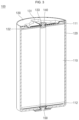
- FIG. 1 is a cross-sectional view of a secondary battery 100 according to an embodiment of the present disclosure
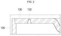
- FIG. 2 is an enlarged view of the portion II in FIG. 1
- FIG. 3 is a perspective cross-sectional view of the secondary battery 100 shown in FIG. 1 .
- the secondary battery 100 includes an electrode assembly 110, a can 120, a cap plate 130, a plug 140, and a terminal 150.
- the electrode assembly 110 includes a first electrode plate, a second electrode plate, and a separator.
- the first electrode plate may be any one of a negative electrode plate and a positive electrode plate.
- the first electrode plate may include a current collector plate (e.g., a negative electrode current collector plate) made of a thin conductive metal plate, such as copper or nickel foil or mesh, and may have a coated portion (e.g., a negative electrode coated portion) at where an active material (e.g., a negative electrode active material) is coated and an uncoated portion (e.g., a negative electrode uncoated portion) 111 at where the negative electrode active material is not coated.
- the negative electrode active material may include, for example, a carbon-based material, silicon (Si), tin (Sn), tin oxide, a tin alloy composite, a transition metal oxide, lithium metal nitrite, or a metal oxide.
- the second electrode plate may be the other one of the negative electrode plate and the positive electrode plate.
- the second electrode plate may include a current collector plate (e.g., a positive electrode current collector plate) made of a thin conductive metal plate, such as aluminium foil or mesh, and may have a coated portion (e.g., a positive electrode coated portion) at where an active material (e.g., a positive electrode active material) is coated and an uncoated portion (e.g., a positive electrode uncoated portion) 112 at where the positive electrode active material is not coated.
- the positive electrode active material may include a chalcogenide compound, for example, a complex metal oxide, such as LiCoO 2 , LiMn 2 O 4 , LiNiO 2 , or LiNiMnO 2 .
- the separator is interposed between the first electrode plate and the second electrode plate to prevent a short circuit between the first electrode plate and the second electrode plate.
- the separator may be made of, for example, polyethylene, polypropylene, or a porous copolymer of polyethylene and polypropylene.
- the electrode assembly 110 is formed by stacking the first electrode plate, the separator, and the second electrode plate in that order such that the uncoated portion 111 of the first electrode plate is aligned on (or protrudes from) one side (e.g., the upper side in the drawing), and the uncoated portion 112 of the second electrode plate is aligned on (or protrudes from) the opposite side (e.g., the lower side in the drawing), and is wound to have a hollow center.
- the can 120 may be formed in a cylindrical shape.
- the can 120 has a bottom 121 formed in a disk shape and a side surface 122 extending upwardly from an edge of the bottom 121. Because the upper end of the can 120 is open, the electrode assembly 110 is inserted into the inside of the can 120 through the upper end of the can 120, and the upper end of the can 120 can then be closed by the cap plate 130.
- the can 120 has a hole 121a at a center of the bottom 121 through which the terminal 150 is installed.
- the bottom 121 and the side surface 122 of the can 120 may be integrally formed and may be made of, for example, steel, a steel alloy, aluminium, or an aluminium alloy.
- FIG. 4 is a plan view of a cap plate 130 of a secondary battery 100 according to an embodiment of the present disclosure
- FIG. 5 is a bottom view of the cap plate 130 shown in FIG. 4 .
- the cap plate 130 is formed in a disk shape corresponding to the upper end of the can 120 to be coupled to the upper end of the can 120.
- a step may be formed on the inner diameter side of the upper end of the can 120 so that the cap plate 130 can be more stably coupled to the upper end of the can 120, and the cap plate 130 may be seated on the step (see, e.g., FIG. 2 ).
- welding is performed along the boundary between the cap plate 130 and the can 120 to fix the cap plate 130 and the can 120.
- the cap plate 130 includes a welding portion 131, a notch 132, and an injection opening 133.
- the welding portion 131 is welded in direct contact with the uncoated portion 111 of the first electrode plate of the electrode assembly 110.
- a region of the cap plate 130 other than the welding portion 131 may be spaced apart from the electrode assembly 110.
- the welding portion 131 may be formed by being concavely recessed from the cap plate 130 toward the inside of the can 120.
- the welding portion 131 may be formed such that the bottom surface of the welding portion 131, when the cap plate 130 is coupled to the can 120, is located, for example, in a range of about 0.1 mm to about 0.2 mm lower than a point (that is, a level or height) at where the upper end of the uncoated portion 111 is located when the electrode assembly 110 is accommodated in the can 120.
- the welding portion 131 contacts the uncoated portion 111 of the first electrode plate by lightly pressing the same. Accordingly, the welding portion 131 is in close contact with and electrically connected to the uncoated portion 111 of the first electrode plate.
- the welding portion 131 may radially extend from the center of the cap plate 130. Accordingly, the cap plate 130 and the electrode assembly 110 may be fixed by performing welding along the direction in which the welding portion 131 extends from the outside of the cap plate 130 (e.g., in a radial direction).
- the welding portion 131 is illustrated as being formed in a cross shape so that welding can be performed linearly in four places (see the portion indicated by thick solid lines in FIGS. 4 and 5 ), but the number and shape thereof can be appropriately varied.
- the welding portion 131 may radially extend in three branches on the basis of the center of the cap plate 130 so that welding can be performed at three locations.
- a region having a smaller diameter than the length of the welding portion 131 extending at the center of the cap plate 130 and concavely recessed together with the welding portion 131 can be seen.
- a wider contact area e.g., a conducting area
- the upper region is illustrated as being formed in a circular shape, but the shape may be appropriately changed.
- the area may be formed in a rectangular shape.
- the notch 132 acts as a safety vent. For example, when gas is generated inside the can 120, the notch 132 may spontaneously burst due to the resulting pressure to release the gas and pressure, thereby preventing an explosion.
- the notch 132 may be formed along the circumference of the cap plate 130 outside the welding portion 131. Therefore, because the notch 132 does not interfere with the welding portion 131, the function thereof can perform as intended. In addition, when the notch 132 bursts, a relatively wide rupture area is formed, and thus, gas and pressure can be rapidly released from the can 120.
- the notch 132 may be formed in an inner surface of the cap plate 130. Accordingly, the notch 132 may not be unintentionally damaged or corroded by external factors.
- the injection opening 133 is for injecting electrolyte into the can 120 after coupling the cap plate 130 to the can 120 and may be formed at the center of the cap plate 130.
- the plug 140 is for sealing the injection opening 133 after injecting the electrolyte solution into the can 120 and may be installed by riveting.
- the plug 140 includes a shank 141 extending through the injection opening 133, a head 142 disposed on one end of the shank 141 and formed larger than the injection opening 133 and supported on the outer surface of the cap plate 130, and a bucktail 143 supported on the inner surface of the cap plate 130 by having the other end of the shank 141 deformed to be larger than the injection opening 133.
- the bucktail 143 When the plug 140 is installed into the injection opening 133, the bucktail 143 is positioned inside the hollow of the electrode assembly 110. Accordingly, a separate space for the bucktail 143 need not be provided inside the can 120, and the secondary battery 100 can be designed more compactly as a whole.
- the terminal 150 is installed in the hole 121a in the bottom 121 of the can 120 and is electrically connected to the uncoated portion 112 of the second electrode plate of the electrode assembly 110.
- the terminal 150 may also be installed by riveting. Therefore, similar to the plug 140, the terminal 150 may include a shank 151 extending through the hole 121a, a head 152 disposed at one end of the shank 151, formed to be larger than the hole 121a, and supported on the outer surface of the bottom 121 of the can 120, and a bucktail 153 deformed to be larger than the hole 121a to be supported on the inner surface of the bottom 121 of the can 120 and in contact with the uncoated portion 112 of the second electrode plate of the electrode assembly 110.
- an insulating member may be installed between the can 120 and the terminal 150 to electrically insulate the same from each other.
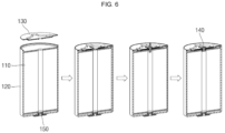
- FIG. 6 illustrates steps of a process of assembling a secondary battery according to an embodiment of the present disclosure.
- the electrode assembly 110 is inserted into the can 120, and the cap plate 130 is then coupled to the can 120 are shown.
- the cap plate 130 may be stably coupled by being seated on the step at the upper end of the can 120.
- the can 120 and the cap plate 130 are welded along the boundary therebetween to fix the cap plate 130 to the can 120. Further, welding is performed from the outside of the cap plate 130 along the direction in which the welding portion 131 extends to fix the cap plate 130 to the electrode assembly 110.
- the fixing of the cap plate 130 to the can 120 and to the electrode assembly 110 may be performed in any order.
- the cap plate 130 may first be welded to the can 120 and then welded to the electrode assembly 110, may first be welded to the electrode assembly 110 and then welded to the can 120, or may be almost concurrently (or simultaneously) welded to the can 120 and the electrode assembly 110.
- an electrolyte may be injected into the can 120 through the injection opening 133 in the cap plate 130, and the plug 140 may then be installed in the injection opening 133 to finish to secondary battery 100.
- the beading part and the crimping part present in a conventional secondary battery can be omitted. Accordingly, the space inside the can conventionally used to form the beading part and the crimping part can be further allocated for the electrode assembly, and thus, the battery capacity can be improved. In addition, because the beading part and the crimping part are not formed, not only the process time can be shortened but also cost reduction can be achieved.
Landscapes
- Chemical & Material Sciences (AREA)
- Chemical Kinetics & Catalysis (AREA)
- Electrochemistry (AREA)
- General Chemical & Material Sciences (AREA)
- Engineering & Computer Science (AREA)
- Manufacturing & Machinery (AREA)
- Materials Engineering (AREA)
- Sealing Battery Cases Or Jackets (AREA)
- Connection Of Batteries Or Terminals (AREA)
Applications Claiming Priority (1)
| Application Number | Priority Date | Filing Date | Title |
|---|---|---|---|
| KR1020220152408A KR102614339B1 (ko) | 2022-11-15 | 2022-11-15 | 이차전지 |
Publications (1)
| Publication Number | Publication Date |
|---|---|
| EP4439748A1 true EP4439748A1 (de) | 2024-10-02 |
Family
ID=88647655
Family Applications (1)
| Application Number | Title | Priority Date | Filing Date |
|---|---|---|---|
| EP23206856.9A Pending EP4439748A1 (de) | 2022-11-15 | 2023-10-30 | Sekundärbatterie |
Country Status (4)
| Country | Link |
|---|---|
| US (1) | US20240162538A1 (de) |
| EP (1) | EP4439748A1 (de) |
| KR (2) | KR102614339B1 (de) |
| CN (1) | CN118054165A (de) |
Families Citing this family (4)
| Publication number | Priority date | Publication date | Assignee | Title |
|---|---|---|---|---|
| KR20250137229A (ko) * | 2024-03-11 | 2025-09-18 | 삼성에스디아이 주식회사 | 이차 전지 |
| KR20250137228A (ko) * | 2024-03-11 | 2025-09-18 | 삼성에스디아이 주식회사 | 이차 전지 |
| WO2025220847A1 (ko) * | 2024-04-16 | 2025-10-23 | 삼성에스디아이(주) | 이차전지 및 이를 갖는 배터리 팩 |
| WO2025230317A1 (ko) * | 2024-04-30 | 2025-11-06 | 삼성에스디아이(주) | 이차전지 및 이차전지의 제조 방법 |
Citations (5)
| Publication number | Priority date | Publication date | Assignee | Title |
|---|---|---|---|---|
| JP2008262826A (ja) * | 2007-04-12 | 2008-10-30 | Hitachi Maxell Ltd | コイン形非水電解液二次電池 |
| EP3046158B1 (de) * | 2015-01-14 | 2019-10-09 | Samsung SDI Co., Ltd. | Wiederaufladbare batterie und packung dafür |
| CN113809485A (zh) * | 2021-09-28 | 2021-12-17 | 惠州市恒泰科技股份有限公司 | 钢壳扣式电池及其制备方法 |
| CN114824674A (zh) * | 2022-03-28 | 2022-07-29 | 蓝京新能源(嘉兴)有限公司 | 一种高体积利用率圆柱型电池及其组装工艺 |
| KR20220132994A (ko) * | 2021-03-24 | 2022-10-04 | 삼성에스디아이 주식회사 | 이차 전지 |
Family Cites Families (2)
| Publication number | Priority date | Publication date | Assignee | Title |
|---|---|---|---|---|
| KR101279994B1 (ko) * | 2010-10-15 | 2013-07-05 | 주식회사 엘지화학 | 전극리드에 안전부재가 위치한 구조의 캡 어셈블리 및 이를 포함하고 있는 원통형 전지 |
| JP2015022862A (ja) * | 2013-07-18 | 2015-02-02 | 株式会社豊田自動織機 | 溶接方法及び蓄電装置 |
-
2022
- 2022-11-15 KR KR1020220152408A patent/KR102614339B1/ko active Active
-
2023
- 2023-09-08 US US18/464,026 patent/US20240162538A1/en active Pending
- 2023-10-24 CN CN202311385949.3A patent/CN118054165A/zh active Pending
- 2023-10-30 EP EP23206856.9A patent/EP4439748A1/de active Pending
- 2023-12-12 KR KR1020230179251A patent/KR20240071350A/ko active Pending
Patent Citations (5)
| Publication number | Priority date | Publication date | Assignee | Title |
|---|---|---|---|---|
| JP2008262826A (ja) * | 2007-04-12 | 2008-10-30 | Hitachi Maxell Ltd | コイン形非水電解液二次電池 |
| EP3046158B1 (de) * | 2015-01-14 | 2019-10-09 | Samsung SDI Co., Ltd. | Wiederaufladbare batterie und packung dafür |
| KR20220132994A (ko) * | 2021-03-24 | 2022-10-04 | 삼성에스디아이 주식회사 | 이차 전지 |
| CN113809485A (zh) * | 2021-09-28 | 2021-12-17 | 惠州市恒泰科技股份有限公司 | 钢壳扣式电池及其制备方法 |
| CN114824674A (zh) * | 2022-03-28 | 2022-07-29 | 蓝京新能源(嘉兴)有限公司 | 一种高体积利用率圆柱型电池及其组装工艺 |
Also Published As
| Publication number | Publication date |
|---|---|
| KR102614339B1 (ko) | 2023-12-15 |
| KR20240071350A (ko) | 2024-05-22 |
| US20240162538A1 (en) | 2024-05-16 |
| CN118054165A (zh) | 2024-05-17 |
Similar Documents
| Publication | Publication Date | Title |
|---|---|---|
| EP4439748A1 (de) | Sekundärbatterie | |
| US11581600B2 (en) | Venting device | |
| EP4216345A1 (de) | Sekundärbatterie | |
| EP3799198B1 (de) | Sekundärbatterie | |
| KR102824568B1 (ko) | 이차전지 | |
| US20230216134A1 (en) | Secondary battery | |
| EP4195400B1 (de) | Sekundärbatterie | |
| US11011809B2 (en) | Rechargeable battery | |
| US12562403B2 (en) | Secondary battery | |
| US12476310B2 (en) | Secondary battery and manufacturing method of secondary battery | |
| KR102860189B1 (ko) | 이차전지 | |
| KR102853426B1 (ko) | 이차전지 | |
| US20260031495A1 (en) | Secondary battery and method of manufacturing same | |
| EP4451435A2 (de) | Sekundärbatterie | |
| US20250385354A1 (en) | Rechargeable battery | |
| US20250070331A1 (en) | Secondary battery | |
| US20240332685A1 (en) | Secondary battery |
Legal Events
| Date | Code | Title | Description |
|---|---|---|---|
| PUAI | Public reference made under article 153(3) epc to a published international application that has entered the european phase |
Free format text: ORIGINAL CODE: 0009012 |
|
| STAA | Information on the status of an ep patent application or granted ep patent |
Free format text: STATUS: REQUEST FOR EXAMINATION WAS MADE |
|
| 17P | Request for examination filed |
Effective date: 20231030 |
|
| AK | Designated contracting states |
Kind code of ref document: A1 Designated state(s): AL AT BE BG CH CY CZ DE DK EE ES FI FR GB GR HR HU IE IS IT LI LT LU LV MC ME MK MT NL NO PL PT RO RS SE SI SK SM TR |