EP3311864A1 - Dispositif d'injection automatique - Google Patents
Dispositif d'injection automatique Download PDFInfo
- Publication number
- EP3311864A1 EP3311864A1 EP17203224.5A EP17203224A EP3311864A1 EP 3311864 A1 EP3311864 A1 EP 3311864A1 EP 17203224 A EP17203224 A EP 17203224A EP 3311864 A1 EP3311864 A1 EP 3311864A1
- Authority
- EP
- European Patent Office
- Prior art keywords
- housing
- trigger
- boot
- outer casing
- automatic injection
- Prior art date
- Legal status (The legal status is an assumption and is not a legal conclusion. Google has not performed a legal analysis and makes no representation as to the accuracy of the status listed.)
- Withdrawn
Links
Images


Classifications
-
- A—HUMAN NECESSITIES
- A61—MEDICAL OR VETERINARY SCIENCE; HYGIENE
- A61M—DEVICES FOR INTRODUCING MEDIA INTO, OR ONTO, THE BODY; DEVICES FOR TRANSDUCING BODY MEDIA OR FOR TAKING MEDIA FROM THE BODY; DEVICES FOR PRODUCING OR ENDING SLEEP OR STUPOR
- A61M5/00—Devices for bringing media into the body in a subcutaneous, intra-vascular or intramuscular way; Accessories therefor, e.g. filling or cleaning devices, arm-rests
- A61M5/178—Syringes
- A61M5/20—Automatic syringes, e.g. with automatically actuated piston rod, with automatic needle injection, filling automatically
- A61M5/2033—Spring-loaded one-shot injectors with or without automatic needle insertion
-
- A—HUMAN NECESSITIES
- A61—MEDICAL OR VETERINARY SCIENCE; HYGIENE
- A61M—DEVICES FOR INTRODUCING MEDIA INTO, OR ONTO, THE BODY; DEVICES FOR TRANSDUCING BODY MEDIA OR FOR TAKING MEDIA FROM THE BODY; DEVICES FOR PRODUCING OR ENDING SLEEP OR STUPOR
- A61M5/00—Devices for bringing media into the body in a subcutaneous, intra-vascular or intramuscular way; Accessories therefor, e.g. filling or cleaning devices, arm-rests
- A61M5/178—Syringes
- A61M5/20—Automatic syringes, e.g. with automatically actuated piston rod, with automatic needle injection, filling automatically
-
- A—HUMAN NECESSITIES
- A61—MEDICAL OR VETERINARY SCIENCE; HYGIENE
- A61M—DEVICES FOR INTRODUCING MEDIA INTO, OR ONTO, THE BODY; DEVICES FOR TRANSDUCING BODY MEDIA OR FOR TAKING MEDIA FROM THE BODY; DEVICES FOR PRODUCING OR ENDING SLEEP OR STUPOR
- A61M5/00—Devices for bringing media into the body in a subcutaneous, intra-vascular or intramuscular way; Accessories therefor, e.g. filling or cleaning devices, arm-rests
- A61M5/178—Syringes
- A61M5/31—Details
- A61M5/315—Pistons; Piston-rods; Guiding, blocking or restricting the movement of the rod or piston; Appliances on the rod for facilitating dosing ; Dosing mechanisms
- A61M5/31565—Administration mechanisms, i.e. constructional features, modes of administering a dose
- A61M5/31566—Means improving security or handling thereof
- A61M5/31571—Means preventing accidental administration
-
- A—HUMAN NECESSITIES
- A61—MEDICAL OR VETERINARY SCIENCE; HYGIENE
- A61M—DEVICES FOR INTRODUCING MEDIA INTO, OR ONTO, THE BODY; DEVICES FOR TRANSDUCING BODY MEDIA OR FOR TAKING MEDIA FROM THE BODY; DEVICES FOR PRODUCING OR ENDING SLEEP OR STUPOR
- A61M5/00—Devices for bringing media into the body in a subcutaneous, intra-vascular or intramuscular way; Accessories therefor, e.g. filling or cleaning devices, arm-rests
- A61M5/178—Syringes
- A61M5/20—Automatic syringes, e.g. with automatically actuated piston rod, with automatic needle injection, filling automatically
- A61M2005/2073—Automatic syringes, e.g. with automatically actuated piston rod, with automatic needle injection, filling automatically preventing premature release, e.g. by making use of a safety lock
- A61M2005/208—Release is possible only when device is pushed against the skin, e.g. using a trigger which is blocked or inactive when the device is not pushed against the skin
-
- A—HUMAN NECESSITIES
- A61—MEDICAL OR VETERINARY SCIENCE; HYGIENE
- A61M—DEVICES FOR INTRODUCING MEDIA INTO, OR ONTO, THE BODY; DEVICES FOR TRANSDUCING BODY MEDIA OR FOR TAKING MEDIA FROM THE BODY; DEVICES FOR PRODUCING OR ENDING SLEEP OR STUPOR
- A61M5/00—Devices for bringing media into the body in a subcutaneous, intra-vascular or intramuscular way; Accessories therefor, e.g. filling or cleaning devices, arm-rests
- A61M5/178—Syringes
- A61M5/24—Ampoule syringes, i.e. syringes with needle for use in combination with replaceable ampoules or carpules, e.g. automatic
- A61M2005/2485—Ampoule holder connected to rest of syringe
- A61M2005/2496—Ampoule holder connected to rest of syringe via pivot
-
- A—HUMAN NECESSITIES
- A61—MEDICAL OR VETERINARY SCIENCE; HYGIENE
- A61M—DEVICES FOR INTRODUCING MEDIA INTO, OR ONTO, THE BODY; DEVICES FOR TRANSDUCING BODY MEDIA OR FOR TAKING MEDIA FROM THE BODY; DEVICES FOR PRODUCING OR ENDING SLEEP OR STUPOR
- A61M5/00—Devices for bringing media into the body in a subcutaneous, intra-vascular or intramuscular way; Accessories therefor, e.g. filling or cleaning devices, arm-rests
- A61M5/178—Syringes
- A61M5/31—Details
- A61M5/32—Needles; Details of needles pertaining to their connection with syringe or hub; Accessories for bringing the needle into, or holding the needle on, the body; Devices for protection of needles
- A61M5/3202—Devices for protection of the needle before use, e.g. caps
- A61M5/3204—Needle cap remover, i.e. devices to dislodge protection cover from needle or needle hub, e.g. deshielding devices
Definitions
- the present invention relates to an automatic injection device for delivering a dose of medicine to a user from a medicine containing syringe.
- Automatic injection devices are routinely used in the medical field to deliver a measured dose of medicine to a user. Due to their user friendly design, they can be safely used by patients for self-administration, although in some circumstances they may be used by trained personnel.
- a typical automatic injection device comprises several parts which may include; a syringe containing medicine, a needle fixed to the end of the syringe, a firing mechanism including a spring (or possibly other drive means such as an electric motor or gas drive means), and a trigger.
- the spring may be preloaded, or may be set using a dose setting mechanism such as a dial.
- the firing mechanism is activated by the trigger and forces the medicine through the needle and into the user.
- a mechanical lock may be provided to prevent the trigger from being accidentally pressed. This could be, for example, simply a catch that must be moved out of the way in order to access the trigger.
- Single use, disposable automatic injection devices are delivered to end users in an assembled state, with a medicine syringe contained within the device housing and a needle fixed to the end of the syringe.
- the projecting end of the needle is contained within an rubber or elastomer "boot".
- boot forms an interference fit around the narrowed end portion of the syringe body.
- the tip of the needle may penetrate the end of the boot.
- an end user must typically open the housing and press a new single-use syringe into position. The single-use syringe will have a needle and boot already in place.
- the injection device may also comprise a boot remover to allow the end user to easily and safely remove the boot and thereby expose the needle.
- the boot remover is fitted around or inside the proximal end of the device prior to insertion of the syringe into the housing.
- the boot protecting the needle is captured by the boot remover, i.e. snaps into place within the boot remover.
- a needle shield may be further provided around the needle, such that the needle remains protected even after the boot has been removed. This is relevant to so-called "auto-injectors" which, in addition to driving the medicine through the needle, perform an initial step of inserting the needle through the skin using the force provided by the injection spring (or possible a secondary spring).
- a user When a single use automatic injection device is to be used, a user should first remove the boot remover and boot to expose the needle. NB. the needle remains surrounded by the needle shield at least in the case of an auto-injector. The user will then release the mechanical lock, such that the trigger can be pressed. The user can then place the auto-injector against the surface of the skin and press the trigger to push the needle through the skin and force the medicine through the needle.
- a carriage and carriage-return spring may cause the needle to be returned to a position within the needle shield.
- a problem with single use automatic injection devices occurs when a user forgets to first remove the boot, and, instead, operates the trigger with the boot still in place. This is particularly likely in the case of an auto-injector, where the needle and boot are not readily visible. If the boot is not removed before firing, no drug is delivered to the user. Furthermore, since the medicine will now be under pressure, there is a risk that the user may inadvertently empty the syringe contents into the air if, when realising their error, they subsequently remove the boot.
- Waste may also be undesirable due to cost implications: some medicines can be extremely expensive. Therefore, there exists a need to provide an automatic injection device that overcomes the problem of a device being fired prior to removal of a boot.
- US2012/0095408 discloses an injection device including a multi-use drive assembly and a single use disposable syringe assembly.
- the device is configured such that removal of a boot, covering the syringe needle, unlocks the device for use.
- WO2011/003979 discloses and injection device in which a needle on a syringe is protected by a cap. Removal of the cap primes the device and configures the device for injection.
- an automatic injection device for delivering a dose from a medicine containing syringe.
- the automatic injection device comprises a housing for containing the syringe, a force applicator for applying a force to eject medicine from the syringe, a trigger coupled to the force applicator for releasing the force applicator to cause an injection, wherein the trigger is attached to the housing and is arranged to release the force applicator when the trigger is moved axially by a user's finger in a proximal direction relative to the housing, the automatic injection device further comprising an outer casing, wherein the housing is located within the outer casing, and is axially moveable within the outer casing, wherein the outer casing comprises a first opening located at a proximal end and a second opening located at a distal end, wherein the housing is further arranged such that a proximal end of the housing can pass through the first opening of the outer casing, and the trigger can pass through the
- the automatic injection device further comprises a boot covering a needle attached to the syringe to protect and maintain sterility of the needle, and a mechanical interlock.
- the mechanical interlock prevents actuation of the trigger prior to removal of the boot.
- the first mechanical interlock allows for actuation of the trigger or commencement of an actuation sequence.
- the device further comprises an elastic membrane covering the second opening of the outer casing, wherein the elastic membrane is for preventing finger access to the inside of the outer casing. In a first position the housing is disposed proximally relative to the outer casing, such that the proximal end of the housing projects through the first opening of the outer casing, the trigger is held within the outer casing, and the elastic membrane prevents finger access to the trigger.
- the housing In a second position the housing is disposed distally relative to the outer casing, such that at least a part of the trigger projects from the second opening of the outer casing and the elastic membrane is displaced in a distal direction by the trigger, allowing finger access to the trigger.
- the present invention overcomes problems associated with current automatic injection devices, where a user can accidentally fire the automatic injection device with the boot still in place. This can result in wasted medicine, which may be expensive to replace.
- the present invention overcomes this by providing a mechanical interlock, such that an automatic injection device cannot be fired prior to removal of the boot.
- the automatic injection device comprises a boot remover for removing the boot.
- the boot remover may be formed integrally with the boot.
- the boot and boot remover are formed as separate discrete components, and configured such that the boot is locked into the boot remover upon insertion of the syringe into the housing.
- the mechanical interlock may comprise a boot remover, wherein the boot remover is configured such that removal of the boot remover from the housing both removes the boot from the needle and facilitates access to the trigger.
- the boot remover may provide said mechanical interlock, the boot remover being arranged at the proximal end of the outer casing, and being further arranged, prior to removal, to hold the housing in the first position, restricting access to the trigger.
- the device may further comprise a biasing device acting between the outer casing and the housing, and arranged such that when the boot remover is removed, the biasing device moves the housing in a distal direction relative to the outer casing to the second position.
- a biasing device acting between the outer casing and the housing, and arranged such that when the boot remover is removed, the biasing device moves the housing in a distal direction relative to the outer casing to the second position.
- the device may further comprise a second mechanical interlock for detecting pressure applied to the device by the user's skin following removal of the boot, and configured to prevent actuation of the trigger in the absence of pressure and to allow actuation when sufficient pressure is detected.
- the second mechanical interlock may be provided by a biasing device acting between the outer casing and the housing, wherein the biasing device is arranged to bias the housing in the first position, thereby restricting access to the trigger.
- the boot remover may provide said first mentioned mechanical interlock, the boot remover being arranged at the proximal end of the outer casing and being further arranged, prior to removal, to prevent the housing from being pressed against the skin, thereby restricting access to the trigger.
- the proximal end of the housing may be arranged to be pressed against the user's skin to move the housing to the second position.
- Embodiments to be described aim to provide an automatic injection device that cannot be fired until a boot protecting the syringe needle has been removed.
- the aim is to prevent the problem of wasted medicine and user frustration that may otherwise occur.
- Embodiments are described in the context of an auto-injector, that is an automatic injection device that has a spring or springs that not only drives the injection of medicine, but also pushes the needle into the patient's skin. Such a device is referred to as an auto-injector.
- an auto-injector Such a device is referred to as an auto-injector.
- the skilled person will appreciate that the approach may also be applied to automatic injection devices that only drive medicine delivery and do not push the needle into the skin.
- a proximal end of the auto-injector is the end that is closest to the patient's skin when in use, and a “distal” end as being the end furthest from the patient's skin.
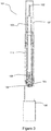
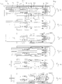
- Figure 1 shows a cross-sectional view of an enclosed button auto-injector 101 comprising a needle 102, syringe 103, boot remover 104, boot 111, trigger 105, trigger cover 106, and housing 107.
- the auto-injector has a proximal end 112 and a distal end 113.
- the housing 107 houses the needle 102 for piercing a user's skin, and the syringe 103 for containing medicine.
- Activation of the trigger 105 actuates a firing mechanism 108.
- the firing mechanism 108 drives the needle into the skin, and forces the medicine through the needle and into the user.
- the device also includes a carriage 114 and carriage return spring 115 within which the syringe 103 is mounted.
- the trigger cover 106 is removably attached to the housing 107 such that it covers the trigger 105. This provides a physical barrier that prevents the user from accidentally activating the trigger 105. Any suitable mechanical interlock for preventing activation of the trigger 105, such as a trigger lock, may be used instead of the trigger cover 106.
- a trigger lock may be used instead of the trigger cover 106.
- the trigger cover 106 may be secured to the housing 107 by any suitable connection type.
- the trigger cover 106 has ridges 109 for slotting into shoulders 110 formed in the housing 107.
- the boot 111 is arranged to prevent contamination of the needle 102.
- the boot remover 104 is connected to the boot, and facilitates removal of the boot.
- the boot remover 104 extends over the outer surface of the housing 107 and over the ridges 109 of the trigger cover 106. By doing so, the boot remover 104 prevents any lateral displacement of ridges 109, and therefore prevents the ridges 109 from being moved out of the shoulders 110, preventing removal of the trigger cover 106.
- the boot remover 104 may provide support to the ridges 109, holding them in place within the shoulders 110.
- Figure 2 shows the boot remover 104 partially removed from the housing 107, no longer preventing the ridges 109 from lateral movement.
- the ridges 109 are prestressed and splay outwardly upon removal of the boot remover 104 to disengage from the shoulders 110.
- the ridges may by displaced outwardly by a separate biasing mechanism, e.g. a spring.
- Figure 3 shows the boot remover 104 totally removed from the device 101, and the trigger cover 106 partially removed. As a result, the trigger 105 is now exposed.
- This arrangement forces a user to perform the step of removing the boot 111 using the boot remover 104 before pressing the trigger 105. By doing so, accidentally activating the enclosed button auto-injector 101 while the boot 111 is still in place is not possible.
- boot remover 104 can prevent removal of the trigger cover 106.
- the boot remover 104 may act as an interlock to a button, where the button may be used to facilitate removal of the trigger cover 106.
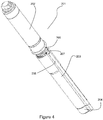
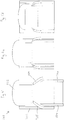
- FIG. 4 illustrates an embedded pin or rod auto-injector 201, comprising a firing mechanism housing 202, a syringe housing 203 containing a syringe, needle and boot (not shown), and a boot remover 204.
- the firing mechanism housing 202 is separate from the syringe housing 203, and therefore actuation of the firing mechanism within the firing mechanism housing 202 will not actuate the injection.
- a lip 205 on the firing mechanism housing 202 displaces a rod 207 residing in a channel 206 in the syringe housing 203. Assembly may be achieved by screwing the firing mechanism housing 202 into the syringe housing 203.
- Figure 5 shows the firing mechanism housing 202 fully engaged with the syringe housing 203.
- the lip 205 has displaced the rod 207, which has in turn displaced the boot remover 204, removing it from the syringe housing 203.
- the boot will be removed before the auto-injector 201 can be actuated.
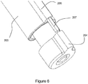
- Figure 6 shows a close up view of the rod 207 displacing the boot remover 204.
- the boot remover 204 may have a peg 208 that protrudes into the channel 206 for engaging with the rod, shown in Figure 7 .
- This arrangement ensures that the boot remover 204 can be displaced and ejected without subsequent protrusion of the rod 207, which may otherwise lead to an obstruction when administering an injection.
- Figure 7 also shows a track 209 running along the inner surface of the syringe housing 203, for receiving a ridge (not shown) formed on the boot remover 204, ensuring proper alignment of the boot remover 204.
- the embedded rod auto-injector 201 may comprise a spring located within the syringe housing 203 that acts to push the rod 207 backwards (toward firing mechanism housing 202) in order to ensure that the rod 207 returns from the protruding position upon disassembly. This is relevant in particular to a re-useable device.
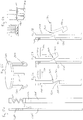
- Figure 8 shows a cross-section of a helical linkage auto-injector 301, comprising a boot remover 302, boot 312, housing 303, trigger 304 and trigger lock 305.
- the boot remover 302 has a radially projecting peg 306 and a key 307.
- the housing 303 has an axial track (not shown) for receiving the key 307, and is arranged to prevent rotation of the boot remover 302 while the key 307 is engaged with the axial track. Any number of ways can be used to prevent rotation of the boot remover 302 while it is attached to the helical linkage auto-injector 301. The use of a key 307 and axial track is just one of many possible alternatives.
- the housing 303 contains a rod 308 with a helical track 310 (not shown in Figure 8 ) running around its circumference.
- the helical track 310 is arranged to receive the peg 306. Note that when the peg 306 is engaged with the helical track 310, the connection between the peg 306 and helical track 310 may be sufficient to prevent rotational movement of the boot remover 302. The key 307 and axial track may then not be required.
- At one end of the rod 308 there is a trigger lock 305 for preventing actuation of the trigger 304.
- the trigger lock 305 features is shaped such that, in one orientation of the rod 308 and trigger lock 305, the trigger 304 cannot be activated, but, when the rod and trigger lock are rotated 180 degrees, the trigger 304 can be activated.
- the shape may be a stepped shape for example.
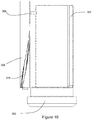
- Figure 9 shows a perspective view of the boot remover 302, showing the peg 306 and a key 307, whilst Figure 10 shows the peg 306 engaging with the helical track 310 on the rod 308.
- Figure 11 shows a close up view of the trigger 304 and trigger lock 305.
- the trigger 304 has a lip 311 that abuts the trigger lock 305, and prevents downward motion of the trigger 304.
- the boot 312 is removed using the boot remover 302
- the axial motion of the peg 306 causes the rod 308 to rotate due to the interaction between the peg 306 and helical track 310.
- the trigger lock 305 being connected to the rod 308, also rotates.
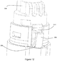
- Figure 12 shows a close up view of the trigger 304 and trigger lock 305 after the boot remover 302 has been removed.
- the trigger lock 305 no longer blocks the path of the lip 311, allowing the trigger 304 to be freely pushed downwards, activating the auto-injector.
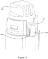
- Figure 13 shows the trigger 304 following actuation.
- the helical linkage auto-injector 301 cannot be fired while the boot remover 302 is still in place. As the boot remover 302, along with the boot 312, is removed, the trigger lock 305 is disengaged. A user can then press the trigger 304 and activate the auto-injector 301.
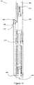
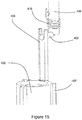
- Figure 14 shows a cross sectional view of a spring loaded lock auto-injector 401, comprising a boot remover 402, boot 412, housing 403, trigger 404 and trigger lock 405.
- the boot remover 402 has a latch 406 and one or more keys 407 (not shown).
- the housing has one or more a linear, axially extending tracks (not shown) for engaging with the keys 405. This arrangement restricts rotation of the boot remover 402 prior to removal. Any number of ways can be used to prevent rotation of the boot remover 402 while attached to the spring loaded lock auto-injector 401.
- the housing 403 contains a rod 408 with a pin 409 for engaging with the latch 406.
- the housing 403 also contains a torsion spring 410 that connects to the rod 408, providing a torque to the rod 408 when the rod is rotationally displaced from a given orientation.
- At one end of the rod 408 there is a trigger lock 405 for preventing actuation of the trigger 404.
- the trigger lock 405 is shaped such that, in one orientation, the trigger 404 cannot be activated, but, when the trigger lock 405 is rotated by 180 degrees, the trigger 404 can be activated. This may be facilitated by a stepped feature formed in the trigger lock 405.
- the rod In the auto-injector's unarmed state, the rod is rotationally displaced such that a torque is applied to the rod 408 by the torsion spring 410, the rod 408 being held in place by the pin 409 being engaged with the latch 406.
- a perspective view of the latch and pin is shown in Figure 15 .
- Figure 16 shows close up view of the trigger 404 and trigger lock 405 in an unarmed position.
- the trigger 404 has a lip 411 that abuts the trigger lock 405, preventing downward motion of the trigger 404.
- the pin 409 disengages with the latch 406, allowing the rod 408 and trigger lock 405 to rotate due to the torque applied by the torque spring 410.
- the trigger lock 405 no longer prevents the trigger 404 from being pressed.
- Figure 17 shows a close up of the trigger 404 and trigger lock 405 in an armed position. It will be apparent that rotation of the rod 408 has caused the trigger lock 405 to be rotated such that it no longer blocks the path of the lip 411, allowing the trigger 404 to be freely pushed downwards, activating the auto-injector 401.
- the trigger lock in the helical linkage auto-injector and the spring loaded lock auto-injector have been described as having a trigger lock (305; 405) that is arranged to abut the trigger, preventing axial motion of the trigger (304; 404). It is noted that other trigger prevention mechanisms may be used instead.
- the trigger lock may be a cover that prevents access to the trigger, wherein rotation of the rod causes the cover to move to into a position such that it does not prevent access to the trigger.
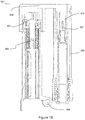
- FIG. 18 shows a cross sectional view of such a hinged auto-injector 501, comprising a boot remover 502, boot 514, syringe housing 503, trigger 504, firing mechanism housing 505, hinge 506 and needle 507.
- a hinged auto-injector 501 When folded, the hinged auto-injector 501 is in an unarmed position, with the boot remover 502 covering both the trigger 504 and the needle 507.
- the boot remover 502 In order to use the hinged auto-injector 501, the boot remover 502 must first be removed. The hinged auto-injector 501 can then be unfolded into a firing position.
- Figure 19 shows the hinged auto-injector 501 with the boot remover 502 and boot 513 removed, but still in the folded configuration.
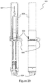
- Figure 20 shows the hinged auto-injector 501 unfolded, as both a cross-section and in plan.
- a latch 508 may be used to lock the hinged auto-injector 501 in the unfolded position.
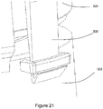
- Figure 21 shows a close up view of the latch 508. Note that the latch 508 may reside on either the firing mechanism 505 or the housing 503. Other suitable mechanisms for locking the hinged auto-injector 501 in position will be readily apparent.
- the hinged auto-injector 501 may further comprise a mechanism that prevents actuation of the trigger 504 before the hinged auto-injector 501 has been fully unfolded.
- An example of such a mechanical interlock comprises a trigger lock comprising an elongate plate 509, shown in Figure 22 .
- the elongate plate 509 features a boss 510 for preventing downward motion of the trigger 504:
- Figure 22 illustrates the "locked" position.
- the elongate plate 509 upon unfolding of the auto-injector, is caused to pivot about a central pivot axis from a position in which downward motion of the trigger 504 is prevented into one in which downward motion of the trigger is possible.
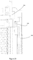
- Figure 23 shows the elongate plate 509 in an unlocked position after unfolding of the device.
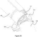
- the elongate plate 509 is shown in more detail in Figure 24 .
- a front end of the trigger lock features an angled face 511 that acts as a spring and holds the elongate plate 509 in a locked position.
- the elongate plate 509 is mounted on a central pivot axle 512.
- interaction with a second latch 513 on the housing 503 causes the angled face 511 to be pressed into the firing mechanism housing 505.
- This action causes the elongate plate 509 to pivot about the pivot axle 506, causing the boss 510 to move clear of the path of the trigger 504.
- Figure 26 shows the hinged auto-injector 501 in a locked position, with the elongate plate 509 disengaged, and the latch 508 engaged.
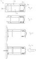
- FIG. 27 shows a cross sectional view of such a floating auto-injector 601, comprising a boot remover 602, housing 603, and trigger 604 attached to the housing 603.
- the housing 603 houses a syringe, needle 609, and firing mechanism, which are not shown Figure 27 .
- the floating auto-injector 601 also comprises an outer casing 605, within which the housing 603 sits.
- the housing 603 is axially movable with respect to the outer casing 605.
- the outer casing 605 has a first opening located at a proximal end and a second opening located at a distal end.
- the first opening is of sufficent size to allow the proximal end of the housing to pass through.
- the second opening is of sufficient size to allow the trigger to pass through.
- a spring 606 acts between the housing 603 and the outer casing 605 to bias the housing 603 in a distal direction.
- the boot remover 602 is arranged to remove the boot (not shown) and further arranged such that when it is attached to the housing 603, the boot remover 602 holds the housing 603 forward in a first proximal position. While the housing 602 is held forward in the first position, the trigger 604 is held within the outer casing 605, and access to the trigger 604 is restricted.
- the floating auto-injector 601 may also comprise an elastic membrane 607 which covers the distal opening, preventing access to the inside of outer casing 605.
- Figure 28 shows the floating auto-injector 601 once the boot remover 602 has been removed.
- the spring 606 pushes the housing 603 distally to a second position, such that the trigger 604 extends through distal opening, stretching the elastic membrane 607, and making the trigger 604 accessible to a user.
- Figure 30 shows the floating auto-injector 601 when the outer casing 605 is pressed against the skin 608.
- the proximal end of the housing 603 is pressed against the skin 608.
- the two cannot move relative to one another, and so the force applied to the trigger 604 axially moves the trigger 604 relative to the housing 603, activating the floating auto-injector 601.
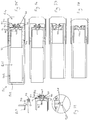
- Figures 31 to 34 show a seventh embodiment, the seventh embodiment being an alternative arrangement of the floating auto-injector embodiment.
- the alternative floating auto-injector 701 is structurally similar to the floating auto-injector 601, but whereas the floating auto-injector 601 has a spring 601 that urges the housing 603 distally with respect to the outer casing 605, the alternative floating auto-injector 701 has a spring 706 which urges the housing 703 proximally with respect to the outer casing 705. When urged forward by the spring 706, access to the trigger 704 is restricted, as shown in Figures 31 and 32 .
- a proximal ending of the housing 703 In order to access the trigger 704, a proximal ending of the housing 703 must be pressed against a user's skin in order for the housing to move rearward relative to the outer casing 705, as in sixth embodiment.
- the boot remover 702 When the boot remover 702 is attached, the boot remover 702 covers a proximal end of the outer casing 705, such that the housing 703 cannot be pressed against the user's skin. Therefore, in order to activate the device 701, the user must first remove the boot remover 702, exposing the proximal end of the housing 703, and then press the proximal end of the housing 703 against the skin, such that the trigger 704 becomes accessible. The device can then be activated by pressing the trigger.
- FIG. 35 shows a cross sectional view of such a toothed wheel auto-injector 801, comprising a boot remover 802, housing 803, trigger 804 and skin sensor 805.
- the housing is arranged to house a syringe carrying needle and force applicator (not shown).
- the boot remover 802 When the boot remover 802 is attached to the device 801, the boot remover 802 abuts the trigger 804, preventing the trigger 804 from being displaced relative to the housing 803.
- Figure 36 shows the toothed wheel auto-injector 801 following removal of the boot remover 802.
- the toothed wheel auto-injector 801 further comprises a rotatable shaft 806 which is coupled to a plunger 807.
- the plunger 807 is coupled to the trigger 804 such that by pressing the trigger 804, the plunger is pushed into a bung of a syringe.
- the plunger 807 may be driven via a drive spring (not shown), or any other means.
- the rotatable shaft 806 is connected to the plunger 807 by a flexible member 808, such as string.
- the rotatable shaft 806 has two toothed portions 809, 810 which extend circumferentially around the outer surface of the rotatable shaft 806.
- the toothed portions 809, 810 are arranged to engage with locking levers 811, 812, which prevent rotation of the shaft 806.
- the plunger 807 is restricted from axially movement due to the connection via the flexible member 809.
- the flexible member 808 may be attached directly to the trigger 804, preventing axial movement of the trigger 804 when the locking levers 811, 812 are engaged.
- the skin sensor 805 is arrange to extend beyond a proximal end of the housing 803, and further arranged such that when the skin sensor 805 is pressed against the skin, the skin sensor 805 is pushed into the housing 803. When pushed into the housing 803, the skin sensor 805 acts on the locking levers 811, 812 via legs 813, 814, disengaging the locking levers 811, 812 from the toothed portions 809, 810 of the shaft 806, allowing rotation of the shaft 806.
- the locking levers 811, 812 are pivotally attached to the housing 803 via pivot points 814, 815.
- the pivot points 815, 816 are located between a part of the levers where the legs 813, 814 of the skin senor 805 act, and a part of the levers that engage with the toothed portions 809, 810. Therefore, when pressed against the skin, the skin sensor 805 causes the locking levers 811, 812 to pivot, disengaging them from the toothed portions 809, 810, and allowing the device 801 to be actuated.
- Figure 37 shows the skin sensor having been pushed into the housing, such that the locking levers 811, 812 have pivoted about the pivot points 815, 816, disengaging from the shaft 806.
- Figure 38 shows the trigger 804 being pushed into the housing.
- Figure 39 shows alternative views of the plunger 807, and shaft 806.
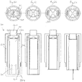
- FIG. 40 shows a cross sectional view of such a toothed element auto-injector 901, comprising a boot remover 902, housing 903, trigger 904 and outer casing 905.
- the boot remover 902 abuts the trigger 904, prior to removal of the boot remover 902. This prevents the trigger 904 from being displaced relative to the outer casing 905 and/or the outer casing 905 to activate the device 901.
- Figure 41 shows the boot remover 902 removed.
- the housing 903 is located within the outer casing 905 and a part of the housing 903 protrudes from a proximal end of the outer casing 905, such that it can be pressed against the skin.
- the outer casing 905 comprises a drive spring 906 and plunger 907, for acting on a bung or plunger of a syringe 908 contained in the housing 903. Pressing the trigger 904 activates the drive spring 906, which drives the plunger 907.
- the device 901 further comprises two locking elements 909, 910 axially fixed within the outer casing 905.
- the locking elements 909, 910 have interlocking teeth which engage with interlocking teeth on the plunger 907, preventing axial movement of the plunger 907.
- the device 901 cannot be activated ( Figure 42 ).
- the housing 903 is axially moveable relative to the outer casing 905, and when pressed against the user's skin, the housing 903 is pushed into the outer casing 905 ( Figure 43 ).
- the outer casing 905 comprises biasing springs 911 which bias the locking elements 909, 910 against the plunger 907 such that the teeth interlock. While teeth have been described, it will be understood by the skilled person that any interlocking feature may be used.
- the housing 903 has two angled surfaces 912, 913 which interact with two angled surfaces 914, 915 on the locking elements 909, 910, when the housing 903 is pressed into the outer casing 905. These angled surfaces cause the locking elements to be radial displaced, disengaging them from the plunger 907 ( Figure 43 - 45 ).
- the boot remover must first be removed and then the device 901 pressed against the skin before pressing the trigger 904 activates the device 901, driving a needle 916 into a user and dispensing medicine contained in the syringe 908.
- FIG. 46 shows a cross sectional view of an auto-injector 1001 according to the tenth embodiment.
- the auto-injector 10001 comprises a boot remover 1002 for removing a boot 1002a, housing 1003, trigger 1004 and skin sensor 1005.
- the housing 1003 houses a syringe carrying medicine, a needle, and drive mechanism (not shown) for driving the needle into a user's skin, and dispensing the medicine.
- the skin sensor 1005 extends proximally from the housing 1002, and is arranged to be pressed against the user's skin.
- the boot remover 1002 covers the skin sensor 1005 such that the skin sensor 1005 cannot be pressed against the skin. With the boot remover 1002 removed ( Figure 47 ), the skin sensor 1005 can be pressed against the skin.
- the skin sensor 1005 has an elongated leg 1006 which abuts a corresponding elongated leg 1007 on the trigger 1004. The abutment prevents the trigger 1004 from being axially displaced.
- the skin sensor 1005 further comprises a helical keyway 1008 which engages with a boss 1009 on an inner surface of the housing 1003.
- a helical keyway 1008 engages with a boss 1009 on an inner surface of the housing 1003.
- FIG 51 shows a cross sectional view of a distal end of an auto-injector 1101 according to the eleventh embodiment.
- the auto-injector 11001 comprises a boot remover (not shown) for removing a boot, housing 1102, trigger 1103 and skin sensor 1104.
- the skin sensor 1104 is arranged to be pressed against the skin, such that it enters the housing 1102.
- the boot remover is arranged such that, prior to removal, it covers a proximal end of the skin sensor 1104, preventing it from being pressed against the skin and into the housing 1102.
- the trigger 1103 is prevented from axial movement in the proximal direction due to an abutment between the trigger 1103 and two flexible legs 1105, 1106 fixed on the inside of the housing 1102.
- the skin sensor 1104 When the boot remover is removed, the skin sensor 1104 is pressed against the skin, such that it moves axially into the housing 1102. The a distal end of the skin sensor 1104 pushes against the flexible legs 1105, 1106, causing them to deform ( Figure 52 ). Once deformed, the flexible legs 1105, 1106 no longer abut the trigger 1103, allowing activation of the device 1101 ( Figure 53 ).
- Figure 55 shows a trigger 1201 for activating an automatic injection device (not shown).
- the trigger 1201 has three latches 1202 which extend from the trigger 1201, and are arranged to project through slots 1203 of a housing 1204 of the auto-injector ( Figure 56 ). This engagement prevents actuation of the trigger 1201.
- the auto injector has three release elements 1205 (a release element is shown in Figure 54 from a side view and front view).
- the release elements 1205 have a de-latching portion 1206, which feature a raised, angled surface 1207 for engaging with the latch 1202 of the trigger 1201.
- the release elements extend beyond a proximal end of the housing 1204 and are arranged such that, when the auto-injector is pressed against the skin, the release elements 1205 are pushed into the housing 1204 and the de-latching portions 1206 engage with, and slide past, the latches 1205 so as to press the latches back through the slots 1203 and allow the trigger 1201 to be actuated ( Figure 57 and 58 ).
- the release elements 1205 are fixed to the housing 1204, and have integral spring elements 1207 between the attachment to the housing and the de-latching portion 1206.
- the spring elements 1207 are arranged to compress when the release elements 1205 are pressed against the skin. Any number of release elements may be used.
- the release elements 1205 are distributed evenly around a circumference having its centre along an axial direction of the housing 1204. This can be seen from Figure 55 , where the three latches 1202, which engage with the release elements 1205, are distributed evenly.
- Figure 59 shows a boot remover 1208 which removes the boot (not shown), and covers the release elements 1205.
- the boot remover 1208 must be removed before the release elements 1205 can be pressed against the skin.
- FIGS 60 to 63 show a top cross sectional view of an auto-injector of the thirteenth embodiment, and a partial cross sectional side view.
- the auto-injector 1301 of the thirteenth embodiment comprises a housing 1302 which houses a syringe and needle, and drive mechanism (not shown) for activating the device 1301; a trigger 1303 coupled to the housing 1302, and arranged to activate the drive mechanism; a boot remover 1304 for removing the boot and covering the proximal end of the device 1301; a skin sensor 1305 protruding proximally beyond the housing 1302 and an out casing 1306; and an elliptical flexible collar 1307 axially fixed to the housing 1302, and located between the trigger 1303 and the housing 1302.
- the elliptical flexible collar 1307 is arranged to sit around a part of the trigger 1303, and prevent the trigger 1303 from being fully depressed when in a first configuration, preventing activation of the device 1301.
- the collar 1307 has a minor axis 1308 which is shorter than the diameter of an upper part of the trigger 1309. This prevents the trigger 1303 from being fully depressed into the housing 1302 ( Figure 60 shows the device 1301 with the boot remover 1304 attached, and 61 shows the device with the boot remover removed).
- the trigger is described as having a diameter, and the collar is describe as being elliptical, both may be any suitable shape such that deformation of the collar allows the trigger to pass through.
- the skin sensor 1305 has an angled surface 1310 at its distal end.
- the skin sensor 1305 When the skin sensor 1305 is pressed against the skin ( figure 62 ), it is moved into the outer casing 1306, and the angled surface 1310 pushes against the vertices defining the major axis, so as to deform the elliptical flexible collar 1307. The deformation causes the minor axis to increase in length, until the trigger 1303 is no longer blocked by the collar 1307.
- the device can then be activated ( figure 63 ).
- the boot remover 1304 covers the skin sensor 1305 prior to removal. Once removed, the skin sensor 1305 may be pressed against the skin.
- FIGS 64 to 68 show a cross section of an auto-injector of the thirteenth embodiment.
- the auto-injector 1401 comprises a housing 1402 housing a syringe, drive mechanism (not shown), and needle 1411; an outer casing 1403 within which the housing 1402 is located; a boot remover 1404 for removing a boot and covering the proximal end of the device 1401; and a trigger 1405.
- the housing 1402 is contained within the outer casing 1403 and arranged to be axially moveable within the outer casing 1403.
- the drive mechanism within the housing 1402 is prevented from being released and activating the device 1401 by being connected to flexible member 1406 which is clamped in two places.
- the auto-injector 1401 further comprises a spring 1407 which acts between the outer casing 1403 and the housing 1402 and biases the housing 1402 towards a proximal end of the outer casing 1403 such that a part of the housing 1402 protrudes from an opening of the proximal end of the outer casing 1403.
- a part of the flexible element 1406 is clamped in a first clamped position 1408 between an outer surface of the housing 1402 and an inner surface of the outer casing 1403.
- the housing 1402 moves into the outer casing 1403, which releases the clamp 1408 ( Figure 66 ).
- the boot remover 1404 prevents the housing 1402 from being pressed against the skin, prior to removal.
- the flexible element 1406 is further clamped in a second position by a butterfly valve 1409 coupled to the housing 1402.
- the trigger 1405 has two release pegs 1410, which engage with the butterfly valve 1409 when the trigger 1405 is displaced. This engagement opens the valve 1409, unclamping the flexible element 1406 from the second clamp ( Figure 67 ).
- the drive mechanism is no longer prevented from being released by the flexible member, and so the device 1401 is activated, driving the needle 1411 and medicine into the user's skin.
- the device 1401 is a further arranged, such that when the housing 1402 is held in the forward position by the spring 1407, the butterfly valve 1409 is held in a position which is inaccessible to the release pegs 1410 of the trigger 1404. This is shown in Figure 65 , where the trigger 1405 is pressed into the housing, but does not reach the valves 1410. While not shown, the trigger 1405 has limited axial movement due to a structural stop, such as a ledge within the outer casing 1403.
Applications Claiming Priority (2)
| Application Number | Priority Date | Filing Date | Title |
|---|---|---|---|
| GB1303472.3A GB2511317A (en) | 2013-02-27 | 2013-02-27 | Automatic injection device |
| EP14707375.3A EP2961449B1 (fr) | 2013-02-27 | 2014-02-27 | Dispositif d'injection automatique |
Related Parent Applications (2)
| Application Number | Title | Priority Date | Filing Date |
|---|---|---|---|
| EP14707375.3A Division EP2961449B1 (fr) | 2013-02-27 | 2014-02-27 | Dispositif d'injection automatique |
| EP14707375.3A Division-Into EP2961449B1 (fr) | 2013-02-27 | 2014-02-27 | Dispositif d'injection automatique |
Publications (1)
| Publication Number | Publication Date |
|---|---|
| EP3311864A1 true EP3311864A1 (fr) | 2018-04-25 |
Family
ID=48092181
Family Applications (2)
| Application Number | Title | Priority Date | Filing Date |
|---|---|---|---|
| EP17203224.5A Withdrawn EP3311864A1 (fr) | 2013-02-27 | 2014-02-27 | Dispositif d'injection automatique |
| EP14707375.3A Active EP2961449B1 (fr) | 2013-02-27 | 2014-02-27 | Dispositif d'injection automatique |
Family Applications After (1)
| Application Number | Title | Priority Date | Filing Date |
|---|---|---|---|
| EP14707375.3A Active EP2961449B1 (fr) | 2013-02-27 | 2014-02-27 | Dispositif d'injection automatique |
Country Status (7)
| Country | Link |
|---|---|
| US (2) | US9981086B2 (fr) |
| EP (2) | EP3311864A1 (fr) |
| JP (1) | JP2016508402A (fr) |
| CN (1) | CN105025954B (fr) |
| GB (1) | GB2511317A (fr) |
| MX (1) | MX2015011019A (fr) |
| WO (1) | WO2014131858A1 (fr) |
Families Citing this family (26)
| Publication number | Priority date | Publication date | Assignee | Title |
|---|---|---|---|---|
| GB2511317A (en) * | 2013-02-27 | 2014-09-03 | Owen Mumford Ltd | Automatic injection device |
| EP3117854A1 (fr) * | 2015-07-15 | 2017-01-18 | Sanofi-Aventis Deutschland GmbH | Dispositif d'administration de medicaments avec un mécanisme de contrôle du protecteur d'aiguille et d'activation du dispositif |
| GB2541227A (en) * | 2015-08-13 | 2017-02-15 | Owen Mumford Ltd | Injector Device |
| US11103650B2 (en) | 2015-11-27 | 2021-08-31 | Sanofi-Aventis Deutschland Gmbh | Injection device |
| WO2017102175A1 (fr) * | 2015-12-14 | 2017-06-22 | Carebay Europe Ltd | Dispositif d'administration de médicament |
| JP6814809B2 (ja) * | 2015-12-30 | 2021-01-20 | ノボ・ノルデイスク・エー/エス | 針シールド発動を有する自動注射器 |
| GB201600988D0 (en) | 2016-01-19 | 2016-03-02 | Owen Mumford Ltd | Auto-injector apparatus |
| ES2903054T3 (es) * | 2016-06-17 | 2022-03-30 | Becton Dickinson Co | Método y aparato para humedecer las superficies internas de la ruta del fluido de un puerto de fluido para aumentar la transmisión de señales ultrasónicas |
| CA3027992C (fr) | 2016-06-22 | 2021-08-03 | Antares Pharma, Inc. | Dispositif de retrait de protege-aiguille |
| US20180015224A1 (en) | 2016-07-13 | 2018-01-18 | California Institute Of Technology | Dampers and Methods for Performing Measurements in an Autoinjector |
| EP3311863A1 (fr) * | 2016-10-24 | 2018-04-25 | Carebay Europe Ltd. | Dispositif d'administration de médicament équipé d'un capuchon |
| EP3320932A1 (fr) | 2016-11-15 | 2018-05-16 | Carebay Europe Ltd. | Dispositif d'administration de médicament équipé d'un capuchon |
| WO2018195764A1 (fr) * | 2017-04-25 | 2018-11-01 | 群康生技股份有限公司 | Stylo d'injection |
| US11338091B2 (en) | 2017-11-09 | 2022-05-24 | Aijex Pharma International Inc. | Needleless injector assemblies and related methods |
| AU2019208338A1 (en) * | 2018-01-19 | 2020-08-20 | Birya Biotech, Inc. | Tool for servicing an auto-injector |
| BR112020018331A2 (pt) * | 2018-03-13 | 2020-12-29 | Mylan Uk Healthcare Ltd. | Dispositivos para injeção de medicamentos e métodos de utilização |
| JP7194756B2 (ja) * | 2018-06-08 | 2022-12-22 | アンタレス・ファーマ・インコーポレーテッド | 自動挿入注射器 |
| WO2020009921A1 (fr) | 2018-07-06 | 2020-01-09 | Becton, Dickinson And Company | Capteur d'écoulement et procédé pour ajuster une mesure d'écoulement de fluide |
| CN109172946B (zh) * | 2018-08-31 | 2023-10-03 | 嘉兴森迈医疗科技有限公司 | 自动注射笔 |
| JP2022502204A (ja) * | 2018-10-05 | 2022-01-11 | フィリップス − メディサイズ エー/エス | カセットを有する自動注射器 |
| JP2022517765A (ja) * | 2019-01-08 | 2022-03-10 | サノフイ | 流体定量供給デバイス |
| CN110404139A (zh) * | 2019-05-22 | 2019-11-05 | 上海久森医疗科技有限公司 | 医用注射装置 |
| WO2021050448A1 (fr) * | 2019-09-09 | 2021-03-18 | West Pharmaceutical Services, Inc. | Mécanismes de course et de verrouillage pour dispositif d'injection |
| USD996606S1 (en) | 2021-03-29 | 2023-08-22 | Owen Mumford Limited | Injector |
| WO2023285152A1 (fr) * | 2021-07-16 | 2023-01-19 | Shl Medical Ag | Mécanisme d'activation dépendant de la séquence utilisant un rotateur |
| CN114504704A (zh) * | 2022-01-26 | 2022-05-17 | 宁波睿爱产品设计有限公司 | 一种注射器 |
Citations (5)
| Publication number | Priority date | Publication date | Assignee | Title |
|---|---|---|---|---|
| US20030212370A1 (en) * | 2002-05-10 | 2003-11-13 | Laurent Barrelle | Passive safety shield system for injection devices |
| WO2007036676A1 (fr) * | 2005-09-27 | 2007-04-05 | Cilag Gmbh International | Dispositif d’auto-injection dote d’un embout de protection d’aiguille comportant des douilles exterieure et interieure |
| GB2467637A (en) * | 2009-02-05 | 2010-08-11 | Medical House Plc | Autoinjector with casing |
| WO2011003979A1 (fr) | 2009-07-08 | 2011-01-13 | Novo Nordisk A/S | Dispositif d'injection protégé contre le gel |
| US20120095408A1 (en) | 2009-05-01 | 2012-04-19 | Owen Mumford Limited | Injection devices |
Family Cites Families (24)
| Publication number | Priority date | Publication date | Assignee | Title |
|---|---|---|---|---|
| GB0206560D0 (en) * | 2002-03-20 | 2002-05-01 | Glaxo Group Ltd | Novel device |
| DK1715903T3 (da) * | 2004-01-23 | 2008-02-25 | Medical House Plc | Injektionsindretning |
| GB2410188B (en) * | 2004-01-23 | 2006-01-25 | Medical House Plc | Injection device |
| GB2414398B (en) * | 2004-05-28 | 2009-04-22 | Cilag Ag Int | Injection device |
| US8251947B2 (en) * | 2006-05-03 | 2012-08-28 | Antares Pharma, Inc. | Two-stage reconstituting injector |
| DE102007031714A1 (de) * | 2007-07-06 | 2009-01-08 | Lts Lohmann Therapie-Systeme Ag | Einweginjektor mit mindestens einem Druckstab und einer Verschlusskappe |
| GB2451665B (en) * | 2007-08-08 | 2012-09-26 | Cilag Gmbh Int | Injection device |
| WO2009040604A1 (fr) * | 2007-09-25 | 2009-04-02 | Becton Dickinson France | Injecteur automatique inséré dans un support externe |
| DK2211946T3 (da) * | 2007-09-25 | 2017-11-13 | Becton Dickinson France | Autoinjektor med positionerbar trigger i aktiv position ved bevægelse af et sikkerhedsværn og indikation af den aktive position |
| GB2461078A (en) | 2008-06-19 | 2009-12-23 | Alice 123 Ltd | Auto injector with sliding outer sleeve |
| WO2011101378A1 (fr) * | 2010-02-18 | 2011-08-25 | Sanofi-Aventis Deutschland Gmbh | Gaine d'aiguille pour un dispositif d'injection |
| EP2364739A1 (fr) * | 2010-03-09 | 2011-09-14 | Sanofi-Aventis Deutschland GmbH | Auto-injecteur réutilisable |
| EP2399629A1 (fr) * | 2010-06-28 | 2011-12-28 | Sanofi-Aventis Deutschland GmbH | Auto-injecteur |
| EP2399627A1 (fr) * | 2010-06-28 | 2011-12-28 | Sanofi-Aventis Deutschland GmbH | Auto-injecteur |
| WO2012045350A1 (fr) * | 2010-10-06 | 2012-04-12 | Tecpharma Licensing Ag | Mécanisme de verrouillage et de retenue pour le protecteur d'aiguille d'un dispositif d'injection |
| EP2438939A1 (fr) * | 2010-10-08 | 2012-04-11 | Sanofi-Aventis Deutschland GmbH | Agencement pour coupler un piston avec une seringue ou un butoir |
| EP2438945A1 (fr) * | 2010-10-08 | 2012-04-11 | Sanofi-Aventis Deutschland GmbH | Moteur réutilisable pour auto-injecteur |
| EP2438941A1 (fr) * | 2010-10-08 | 2012-04-11 | Sanofi-Aventis Deutschland GmbH | Auto-injecteur avec un ressort à torsion |
| EP2468342A1 (fr) * | 2010-12-21 | 2012-06-27 | Sanofi-Aventis Deutschland GmbH | Unité initiale pour auto-injecteur |
| EP2489384A1 (fr) * | 2011-02-18 | 2012-08-22 | Sanofi-Aventis Deutschland GmbH | Auto-injecteur |
| CN103596612B (zh) * | 2011-04-07 | 2016-08-17 | 泰尔茂株式会社 | 液体注入器 |
| EP2583706A1 (fr) * | 2011-10-21 | 2013-04-24 | Sanofi-Aventis Deutschland GmbH | Auto-injecteur |
| GB2511317A (en) * | 2013-02-27 | 2014-09-03 | Owen Mumford Ltd | Automatic injection device |
| BR102014015085B1 (pt) * | 2014-05-29 | 2023-11-14 | M.E.P. Macchine Elettroniche Piegatrici S.P.A. | Unidade de estiramento, aparelho de estiramento e método correspondente |
-
2013
- 2013-02-27 GB GB1303472.3A patent/GB2511317A/en not_active Withdrawn
-
2014
- 2014-02-27 MX MX2015011019A patent/MX2015011019A/es unknown
- 2014-02-27 EP EP17203224.5A patent/EP3311864A1/fr not_active Withdrawn
- 2014-02-27 WO PCT/EP2014/053882 patent/WO2014131858A1/fr active Application Filing
- 2014-02-27 EP EP14707375.3A patent/EP2961449B1/fr active Active
- 2014-02-27 CN CN201480010612.7A patent/CN105025954B/zh active Active
- 2014-02-27 US US14/769,949 patent/US9981086B2/en active Active
- 2014-02-27 JP JP2015559502A patent/JP2016508402A/ja active Pending
-
2018
- 2018-04-11 US US15/950,381 patent/US10864325B2/en active Active
Patent Citations (5)
| Publication number | Priority date | Publication date | Assignee | Title |
|---|---|---|---|---|
| US20030212370A1 (en) * | 2002-05-10 | 2003-11-13 | Laurent Barrelle | Passive safety shield system for injection devices |
| WO2007036676A1 (fr) * | 2005-09-27 | 2007-04-05 | Cilag Gmbh International | Dispositif d’auto-injection dote d’un embout de protection d’aiguille comportant des douilles exterieure et interieure |
| GB2467637A (en) * | 2009-02-05 | 2010-08-11 | Medical House Plc | Autoinjector with casing |
| US20120095408A1 (en) | 2009-05-01 | 2012-04-19 | Owen Mumford Limited | Injection devices |
| WO2011003979A1 (fr) | 2009-07-08 | 2011-01-13 | Novo Nordisk A/S | Dispositif d'injection protégé contre le gel |
Also Published As
| Publication number | Publication date |
|---|---|
| CN105025954B (zh) | 2017-08-08 |
| EP2961449A1 (fr) | 2016-01-06 |
| US10864325B2 (en) | 2020-12-15 |
| CN105025954A (zh) | 2015-11-04 |
| JP2016508402A (ja) | 2016-03-22 |
| EP2961449B1 (fr) | 2017-12-27 |
| GB2511317A (en) | 2014-09-03 |
| GB201303472D0 (en) | 2013-04-10 |
| US20180228974A1 (en) | 2018-08-16 |
| US9981086B2 (en) | 2018-05-29 |
| WO2014131858A1 (fr) | 2014-09-04 |
| US20160015896A1 (en) | 2016-01-21 |
| MX2015011019A (es) | 2016-04-07 |
Similar Documents
| Publication | Publication Date | Title |
|---|---|---|
| US10864325B2 (en) | Automatic injection device | |
| US10765809B2 (en) | Auto-injector for epinephrine injection | |
| US20230141352A1 (en) | Medicament Delivery Device Comprising a Locking Mechanism Having a Lever | |
| EP2753381B1 (fr) | Dispositif pour l'injection automatique de deux doses d'un médicament | |
| US20180272073A1 (en) | Medicament Delivery Device | |
| DK2640448T3 (en) | Drug delivery device | |
| EP2902058B1 (fr) | Dispositif d'injection | |
| DK2782620T3 (en) | autoinjector | |
| US8062255B2 (en) | Auto-injector | |
| DK2640449T3 (en) | DRUG DELIVERY DEVICES | |
| CN110740771A (zh) | 具有中空柱塞杆的自动注射器 | |
| JP2024501680A (ja) | 薬剤送達デバイス |
Legal Events
| Date | Code | Title | Description |
|---|---|---|---|
| PUAI | Public reference made under article 153(3) epc to a published international application that has entered the european phase |
Free format text: ORIGINAL CODE: 0009012 |
|
| STAA | Information on the status of an ep patent application or granted ep patent |
Free format text: STATUS: REQUEST FOR EXAMINATION WAS MADE |
|
| 17P | Request for examination filed |
Effective date: 20171123 |
|
| AC | Divisional application: reference to earlier application |
Ref document number: 2961449 Country of ref document: EP Kind code of ref document: P |
|
| AK | Designated contracting states |
Kind code of ref document: A1 Designated state(s): AL AT BE BG CH CY CZ DE DK EE ES FI FR GB GR HR HU IE IS IT LI LT LU LV MC MK MT NL NO PL PT RO RS SE SI SK SM TR |
|
| STAA | Information on the status of an ep patent application or granted ep patent |
Free format text: STATUS: THE APPLICATION HAS BEEN WITHDRAWN |
|
| 18W | Application withdrawn |
Effective date: 20210630 |