EP3310322B1 - Système de couplage seringue-à-seringue avec embout mâle - Google Patents
Système de couplage seringue-à-seringue avec embout mâle Download PDFInfo
- Publication number
- EP3310322B1 EP3310322B1 EP16739290.1A EP16739290A EP3310322B1 EP 3310322 B1 EP3310322 B1 EP 3310322B1 EP 16739290 A EP16739290 A EP 16739290A EP 3310322 B1 EP3310322 B1 EP 3310322B1
- Authority
- EP
- European Patent Office
- Prior art keywords
- syringe
- coupling
- hub
- male
- coupler
- Prior art date
- Legal status (The legal status is an assumption and is not a legal conclusion. Google has not performed a legal analysis and makes no representation as to the accuracy of the status listed.)
- Active
Links
- 230000008878 coupling Effects 0.000 claims description 129
- 238000010168 coupling process Methods 0.000 claims description 129
- 238000005859 coupling reaction Methods 0.000 claims description 129
- 239000012530 fluid Substances 0.000 claims description 57
- 230000037452 priming Effects 0.000 claims description 8
- 238000012546 transfer Methods 0.000 description 15
- 229940079593 drug Drugs 0.000 description 4
- 239000003814 drug Substances 0.000 description 4
- 239000000463 material Substances 0.000 description 4
- 238000002483 medication Methods 0.000 description 3
- 235000016709 nutrition Nutrition 0.000 description 3
- 230000008901 benefit Effects 0.000 description 2
- 238000013461 design Methods 0.000 description 2
- 238000009423 ventilation Methods 0.000 description 2
- 241001465754 Metazoa Species 0.000 description 1
- 230000009471 action Effects 0.000 description 1
- 238000007792 addition Methods 0.000 description 1
- 230000000903 blocking effect Effects 0.000 description 1
- 239000003086 colorant Substances 0.000 description 1
- 238000004891 communication Methods 0.000 description 1
- 230000001808 coupling effect Effects 0.000 description 1
- 238000012217 deletion Methods 0.000 description 1
- 230000037430 deletion Effects 0.000 description 1
- 235000015872 dietary supplement Nutrition 0.000 description 1
- 238000006073 displacement reaction Methods 0.000 description 1
- 230000009977 dual effect Effects 0.000 description 1
- 239000013536 elastomeric material Substances 0.000 description 1
- 235000013350 formula milk Nutrition 0.000 description 1
- 210000004251 human milk Anatomy 0.000 description 1
- 235000020256 human milk Nutrition 0.000 description 1
- 238000007373 indentation Methods 0.000 description 1
- 230000000977 initiatory effect Effects 0.000 description 1
- 238000009434 installation Methods 0.000 description 1
- 230000013011 mating Effects 0.000 description 1
- 230000007246 mechanism Effects 0.000 description 1
- 238000000034 method Methods 0.000 description 1
- 238000012986 modification Methods 0.000 description 1
- 230000004048 modification Effects 0.000 description 1
- 210000002445 nipple Anatomy 0.000 description 1
- 235000015097 nutrients Nutrition 0.000 description 1
- 230000002093 peripheral effect Effects 0.000 description 1
Images


Classifications
-
- A—HUMAN NECESSITIES
- A61—MEDICAL OR VETERINARY SCIENCE; HYGIENE
- A61J—CONTAINERS SPECIALLY ADAPTED FOR MEDICAL OR PHARMACEUTICAL PURPOSES; DEVICES OR METHODS SPECIALLY ADAPTED FOR BRINGING PHARMACEUTICAL PRODUCTS INTO PARTICULAR PHYSICAL OR ADMINISTERING FORMS; DEVICES FOR ADMINISTERING FOOD OR MEDICINES ORALLY; BABY COMFORTERS; DEVICES FOR RECEIVING SPITTLE
- A61J1/00—Containers specially adapted for medical or pharmaceutical purposes
- A61J1/14—Details; Accessories therefor
- A61J1/20—Arrangements for transferring or mixing fluids, e.g. from vial to syringe
- A61J1/2096—Combination of a vial and a syringe for transferring or mixing their contents
-
- A—HUMAN NECESSITIES
- A61—MEDICAL OR VETERINARY SCIENCE; HYGIENE
- A61J—CONTAINERS SPECIALLY ADAPTED FOR MEDICAL OR PHARMACEUTICAL PURPOSES; DEVICES OR METHODS SPECIALLY ADAPTED FOR BRINGING PHARMACEUTICAL PRODUCTS INTO PARTICULAR PHYSICAL OR ADMINISTERING FORMS; DEVICES FOR ADMINISTERING FOOD OR MEDICINES ORALLY; BABY COMFORTERS; DEVICES FOR RECEIVING SPITTLE
- A61J1/00—Containers specially adapted for medical or pharmaceutical purposes
- A61J1/14—Details; Accessories therefor
- A61J1/20—Arrangements for transferring or mixing fluids, e.g. from vial to syringe
- A61J1/2003—Accessories used in combination with means for transfer or mixing of fluids, e.g. for activating fluid flow, separating fluids, filtering fluid or venting
- A61J1/2048—Connecting means
-
- A—HUMAN NECESSITIES
- A61—MEDICAL OR VETERINARY SCIENCE; HYGIENE
- A61J—CONTAINERS SPECIALLY ADAPTED FOR MEDICAL OR PHARMACEUTICAL PURPOSES; DEVICES OR METHODS SPECIALLY ADAPTED FOR BRINGING PHARMACEUTICAL PRODUCTS INTO PARTICULAR PHYSICAL OR ADMINISTERING FORMS; DEVICES FOR ADMINISTERING FOOD OR MEDICINES ORALLY; BABY COMFORTERS; DEVICES FOR RECEIVING SPITTLE
- A61J1/00—Containers specially adapted for medical or pharmaceutical purposes
- A61J1/14—Details; Accessories therefor
- A61J1/20—Arrangements for transferring or mixing fluids, e.g. from vial to syringe
- A61J1/2089—Containers or vials which are to be joined to each other in order to mix their contents
-
- A—HUMAN NECESSITIES
- A61—MEDICAL OR VETERINARY SCIENCE; HYGIENE
- A61J—CONTAINERS SPECIALLY ADAPTED FOR MEDICAL OR PHARMACEUTICAL PURPOSES; DEVICES OR METHODS SPECIALLY ADAPTED FOR BRINGING PHARMACEUTICAL PRODUCTS INTO PARTICULAR PHYSICAL OR ADMINISTERING FORMS; DEVICES FOR ADMINISTERING FOOD OR MEDICINES ORALLY; BABY COMFORTERS; DEVICES FOR RECEIVING SPITTLE
- A61J1/00—Containers specially adapted for medical or pharmaceutical purposes
- A61J1/14—Details; Accessories therefor
- A61J1/20—Arrangements for transferring or mixing fluids, e.g. from vial to syringe
- A61J1/2003—Accessories used in combination with means for transfer or mixing of fluids, e.g. for activating fluid flow, separating fluids, filtering fluid or venting
- A61J1/2068—Venting means
- A61J1/2075—Venting means for external venting
-
- A—HUMAN NECESSITIES
- A61—MEDICAL OR VETERINARY SCIENCE; HYGIENE
- A61M—DEVICES FOR INTRODUCING MEDIA INTO, OR ONTO, THE BODY; DEVICES FOR TRANSDUCING BODY MEDIA OR FOR TAKING MEDIA FROM THE BODY; DEVICES FOR PRODUCING OR ENDING SLEEP OR STUPOR
- A61M39/00—Tubes, tube connectors, tube couplings, valves, access sites or the like, specially adapted for medical use
- A61M39/10—Tube connectors; Tube couplings
- A61M2039/1088—Tube connectors; Tube couplings having a plurality of male connectors, e.g. Luer connectors
Definitions
- the present invention relates generally to the field of containment, storage, delivery and transfer of fluids, particularly in the medical and pharmaceutical fields, and more particularly to a coupler for devices used in the transfer of medical or nutritional fluids.
- the invention is defined in claim 1.
- invention and/or “embodiment” are used in the following and/or features are presented as optional, this should be interpreted in such a way that the only protection sought is that of the invention as claimed.
- Various fluids such as medications and nutritional fluids are delivered to human or animal patients by dispensing from a syringe.
- a syringe For example, the enteral delivery of formula, breast milk, nutritional supplements, medication and the like to neonatal infants may utilize syringes for manual delivery or automated delivery using a syringe pump.
- Syringes conforming to the new ENFit design standard may include nipple or tip couplings of differing format and larger dimension and volume or displacement than previous syringes.
- WO 2015/034045 relates to a double male connector.
- the present invention is directed to field of containment, storage, delivery and transfer of fluids, particularly in the medical and pharmaceutical fields, and more particularly to a coupler for devices used in the transfer of medical and nutritional fluids.
- the present invention relates to a coupling for transferring fluids between at least two ISO 80369-3 ENFit female connectors or compatible connectors including a male-male hub extending from a first end to a second end, and a fluid delivery conduit extending through the hub from the first end to the second end.
- the ends of the male-male hub are at least partially tapered.
- the two ISO 80369-3 ENFit female connectors are formed with syringes.
- a body is provided and is outwardly offset from the male-male hub.
- at least one connecting member extends between the male-male hub and the body for fixedly positioning the male-male hub relative to the body.
- the present invention relates to a syringe-to-syringe coupling for facilitating the transfer of fluids or medications between two syringes, wherein each of the respective syringes include an ISO 80369-3 ENFit female connector having one or more lugs positioned about an outer periphery thereof.
- the coupling includes a centrally-positioned hub extending from a first end to a second end, a fluid delivery conduit provided within the hub and extending between the first and second ends, and a body outwardly offset from the hub.
- the body is generally cylindrical in shape, and the hub is generally centrally-positioned with respect to the body.
- at least one connecting member extends between an interior portion of the body and the hub for centrally positioning the hub relative to the body.
- the body includes two generally planar members oppositely-positioned and outwardly offset from the hub.
- at least one connecting member fixedly connects the centrally-positioned hub to the oppositely-positioned planar members.
- the present invention relates to a coupling for facilitating the transfer of fluids or medications
- a coupling for facilitating the transfer of fluids or medications including a centrally-positioned hub extending from a first end to a second end, a fluid delivery conduit provided within the hub and extending between the first and second ends, a body outwardly offset from the hub, at least one connecting member connecting the hub with the body, and at least one engagement member for providing coupling engagement with a syringe
- the at least one engagement member is configured for removable coupling engagement with the syringe. According to another example embodiment, the at least one engagement member is configured for permanent coupling engagement with the syringe.
- one of the first or second ends of the hub is in the form of a luer connector for connection with a tube set of a syringe fill pump, and wherein the other of the ends is in the form of an ENFit connector for connection with an ENfit female connector of a syringe.
- the coupler generally includes a central fluid transfer member or hub extending from a first male tip configured to receive a first syringe S to a second male tip configured to receive a second syringe S.
- the hub includes a fluid transfer conduit or lumen extending between the male tips, thereby providing for fluid communication between the first and second syringes S.
- the syringe S includes a female connector FC in the form of an ENFit female connector according to the global design standard ISO 80369-1 (see Figures 5-6 ).
- the female connector FC comprises a pair of thread lugs or ribs R extending along a portion of the periphery of the connector.
- the coupler engages each syringe by a non-threaded, slip-fit connection such that the female connector FC (or an internal surface thereof) engages with a male tip of the coupler.
- a substantially threaded outer collar member or engagement member is provided for engagement with the ribs of the female coupler, thereby providing secure and removable attachment of the coupling with the female connector FC of the syringe S.
- one or more clips, engagement ribs or other engagement members are provided with the coupling for removable or permanent attachment with the female connector FC (and ribs R thereof) of the syringe S.
- At least one of the coupling embodiments shown in the figures is preferably capable of being adapted for connection with a syringe fill pump, for example, for connection with a tube set of the pump at one of the ends and for connection with a female connector FC at the other end.
- example embodiments of the present invention provide for a plurality of configurations to facilitate the transfer of fluids between syringes.
- one or both ends of the coupling can be configured for a slip-fit connection (e.g., frictional engagement), or can additionally include a threaded collar, clips, or other engagement members for providing removable or permanent engagement with the female connector FC and ribs R thereof.
- any one of the connectors (or ends of the coupling) as described herein can be adapted for use with another one of any of the connectors (or ends of the coupling) as described herein.
- Figures 1-6 show a syringe-to-syringe coupler 10 according to an example embodiment of the present invention.
- the coupler 10 is configured to engage two syringes with a removable slip-fit coupling or connection.
- the coupler 10 comprises a central hub 30 (e.g., male-male hub) with two male tips 32 that is generally centrally positioned within an outer body 20 of the coupling 10.
- the central hub 30 comprises a first end 12 having a first male tip 32 and a second end 14 having a second male tip 32.
- the extension of the central hub 30 is generally linear; however, in alternate example embodiments, the extension of the central hub 30 can be generally non-linear, arcuate, or otherwise extend along a desired path between the first and second ends 12, 14.
- the fluid conduit 40 is generally axially positioned within the hub 30 and generally extends entirely therethrough (e.g., extending between the first and second ends through the first and second male tips 32).
- the opening 40 is cylindrical in shape and is generally sized to ensure accuracy of the quantity of fluid being transferred between the syringes S.
- the male tips 32 can be at least partially tapered (as will be described in greater detail below) to provide for sufficiently frictional engagement with the female connector FC.
- the outer body 20 is generally cylindrical in shape and centrally positioned concentrically around the hub 30.
- the outer body 20 is open at each end and the body's outer surface includes ribs 22 to facilitate gripping or twisting of the coupler 10.
- the body 20 can employ indents or other texturing to aid in gripping or twisting, for example, to benefit a user or operator in grasping or gripping the body 20 during attachment or detachment of the coupler 10 to/from one or more syringes S.
- the ends of the hub 30 extend beyond the ends of the outer body 20, for example, such that at least a portion of the male tips 32 protrude beyond the ends of the outer body (see Figure 2 ).
- the outer body 20 can be longer than the hub 30.
- the male tips 232 and the outer periphery of the hub 30 are preferably shaped for substantial frictional, slip-fit coupling engagement with the female connector FC.
- At least one connecting member or, according to the embodiment of the invention, a centrally positioned flange 50 retains the hub 30 concentrically or coaxially within the outer cylindrical housing 20 of the coupling 10.
- the flange 50 can include a radial array of spaced-apart ribs or wedge-shaped fins 52 and openings or passages 54.
- the coupling 10 comprises four fins 52 and four passages 54.
- each of the fins 52 fixes together the outer body 20 and the hub 30.
- passages 54 provide for fluid drainage and/or airflow ventilation through the coupling (and external of the hub 30), for example, to prevent fluids or other matter from remaining stagnant within the coupling and potentially contaminating the coupling 10.
- U.S. Non-Provisional Patent Application Serial No. 14/844,956 discloses alternative connecting members providing ventilation.
- the female connector FC of the first syringe S is slip-fitted over the first male tip 32 of the hub 30 (e.g., providing frictional engagement therebetween), and the female connector FC of the second syringe S is similarly attached to the second male tip 32 (e.g., providing frictional engagement therebetween).
- the lumen 40 provides a passageway or conduit for transferring fluid between the syringes S.
- the slip-fit connection between the male tips 32 and the female connectors FC of the syringes S is preferably a friction fit connection, for example, such that the frictional engagement provided between the outer periphery of the hub 30 and the interior surface of the female connector FC causes sufficient interference to remain snug and connected with the female connector FC of the syringe S.
- a seal is provided by frictional engagement (e.g., preventing leaking) between the female connector FC and each male tip 32 and outer periphery of the hub 30.
- the coupler 10 can be easily disconnected from one or more of the female connectors FC when it is desired to do so (e.g., after fluid transfer between the syringes S is finished).
- grasping and rotating the coupling 10 relative to the syringe S is effective in initiating disconnection of the coupling from the syringe S.
- the hub 30 of the connector 10 is preferably sized and shaped to provide a secure frictional fit with the internal surface of the female connector FC of the syringe S.
- the male tips 32 can comprise a chamfered surface or end 33, which as shown in Figure 6 , is generally angled similarly with respect to an internal surface of the female connector FC and generally offset therefrom.
- the size and shape of the lumen 40 can be configured as desired, for example, to provide the desired volume of dead space or priming space within at least a portion of the lumen, for example, to substantially eliminate any dosing inaccuracies.
- the volume of fluid output from one of the syringes S is substantially equal to the volume of fluid input to the other one of the syringes S.
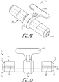
- Figures 7-8 show a syringe-to-syringe coupler 100 according to another example embodiment of the present invention.
- the coupler 100 is configured to engage two syringes S with a removable slip-fit coupling, for example, to facilitate the transfer of fluids between the two syringes S.
- the coupler 100 generally comprises a hub 130 with two male tips 132 of the same size and shape of the previously described hub 30, and a lumen 140 generally axially extending through the entirety of the hub 130 between the two male tips 132.
- the coupler 100 includes a gripping handle 120 attached to a central portion of the hub 130.
- the central portion of the hub 130 comprises a raised rib or protrusion 136, which generally extends entirely around the outer periphery of the hub 130.
- the hub 130 can include a ring or other gripping attachment.
- a portion of the lumen 140 of the male tips 132 preferably comprises a dead space or priming space PS within a contained volume of about 0.05 milliliters (ml).
- the total dead space equals that of the hub fluid conduit 140 that is inserted into a syringe.
- each male tip 132 generally comprises a priming space PS of between about 0.01 milliliters to about 0.20 milliliters, more preferably between about 0.04 milliliters to about 0.12 milliliters, and more preferably between about 0.04691 milliliters to about 0.09382 milliliters.
- the priming space or the fluid occupying the priming space should essentially prime the coupler the same way that another male connector would, for example, a male coupler of a syringe tip, other couplers, etc.
- the priming space in the coupler is configured such that the volume of the fluid delivered through the coupling (for transferring to another syringe, bottle, or other container, etc.) is the volume of the fluid filled within the syringe, bottle, or other container, etc., thereby eliminating any potential dosing inaccuracies through the transfer of fluids.
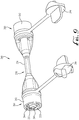
- FIG. 9 shows a syringe-to-syringe coupler 200 according to another example embodiment of the present invention.
- the coupler 200 is configured to removably engage two syringes S with threaded couplings.
- the coupler comprises a hub 230 and a pair of engagement members or coupling elements 260.
- the hub 230 comprises an elongated tubular body 234 with two male coupling tips 232, for example, a first male tip 232 at a first end and a second male tip 232 at a second end.
- the male tips 232 are substantially similar to the male tips 32, 132 as describe above, for example, which comprises a chamfered surface formed on each of the ends.
- the tubular body 234 can be constructed of a rigid or flexible material. In alternate embodiments, the tubular body 234 of the hub 230 may be detachably connected to each male tip 232.
- an opening or fluid conduit 240 extends through the hub 230 from the first end to the second end (e.g., from the first male tip 232, through the tubular body 234, and to the second male tip 232).
- the coupling elements 260 are formed at each end of the hub 230, for example, wherein each coupling element 260 comprises a generally cylindrically shaped outer housing 262 surrounding the respective male tip 232 such that the inner sidewall of the outer housing is generally coaxially arranged with the male tip 232 thereby forming an annular space therebetween.
- the inner sidewall of the outer housing 262 includes screw threads 264 to provide for interengagement with the ribs R of the female connector FC of each respective syringe S.
- the coupling elements 260 and the outer housings 262 thereof can be in the form of an outer collar member, for example, which comprises a cylindrical body comprising threads formed on an internal surface thereof to accommodate removable engagement with the female connector FC (and the ribs R thereof).
- the female connector FC is inserted into the annular space between the male tip 232 and the outer housing 262 such that the ribs R are generally oriented to interengage with the threads 264 on the outer housing.
- Either the coupling 200 or the syringe S is rotated relative to the other to provide for removable engagement therebetween.
- a tethered cap or plug 266 is optionally attached to one or both of the coupling elements 260 to allow closure of one or both of the ends of the fluid conduit as desired.
- other conventional mating fasteners such as are known to persons of ordinary skill in the art can be used, for example, those disclosed in U.S. Non-Provisional Patent Application Serial No. 14/844,956 .
- Figures 10-12 show a syringe-to-syringe coupler 300 according to another example embodiment of the present invention.
- the coupler 300 is configured to removably engage a first syringe S with a slip-fit coupling and a second syringe with a threaded coupling.
- the coupler 300 comprises a hub 330 and fluid conduit 340 of similar size and shape as the hub of previously described couplers 10, 100.
- the coupler 300 comprises an engagement member or coupling element 360, for example, an outer collar member, comprising a generally cylindrically shaped outer housing 362 generally beginning at a center or midpoint of the hub and extending toward one of the male tips 332.
- An inner surface of the outer housing 362 comprises a threaded portion 364 for providing interengagement with the female coupling FC (and ribs R thereof) of the syringe S.
- the coupling element 360 is configured to be coupled to the female connector FC of the syringe S by configuring the ribs R of the female connector FC to interengage with the threads 364 of the outer housing 362, thereby axially moving one of the coupling 360 or female connector FC toward each other.
- the coupling element is generally unscrewed from the female connector.
- the second syringe (not shown) is slip fitted onto the second male tip 332.
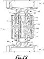
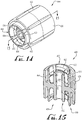
- Figures 13-15 show a syringe-to-syringe coupler 400 according to another example embodiment of the present invention.
- the coupler 400 is configured to removably couple two syringes S together to facilitate the transfer of fluids therebetween.
- the coupler 400 includes a hub 430 and fluid conduit 440 of similar size and shape as the previously described embodiment.
- the coupler 400 includes engagement members or coupling elements 460 provided at each end of the coupler 400 and generally surrounding the hub 430.
- each coupling element 460 comprises four tab members or clips 462 that generally form a circular array at a distance from the hub 430 generally extending from a central portion or midpoint of the hub 430 toward one of the male tips 432.
- An internal portion or wall of at least one of the clips 462 includes a threaded portion 464.
- each of the four clips 462 includes at least a portion of a thread 464.
- the female connector FC of each syringe S can be installed and removed by either pushing and pulling (without twisting) due to the snap connection provided by the split collar and the rib R, or by twisting on and off due to the thread 464 on the clips 462, thus providing a dual-action installation and removal mechanism.
- the hub 430 and coupling elements 460 are coaxially positioned within a cylindrically shaped outer body 420, for example, which is generally similar to the body 20 of Figures 1-6 .
- At least one connecting member or transverse flange 450 is provided for retaining the hub 430 concentrically or coaxially within the outer cylindrical housing 420 of the coupling 400.
- one or more vents 454 can be provided as desired.
- the female connector FC of each syringe S can be installed with the coupling 400 by pushing (without twisting) due to the snap connection provided by the split collar and the rib R (e.g., flexibility of the clips 462), but is generally prevented from being pulled therefrom, for example, unless the syringe S or coupling 400 is generally rotated relative to the other.
- attachment can be provided by twisting on and off due to the thread 464 on the clips 462, for example, whereby engagement of the rib R of the female connector FC with the threads 464 provide axial movement therebetween for attachment or detachment from the female connector FC.
- the allowable flexibility of the clips 462 can be adjusted such that attachment and detachment (pushing, pulling, twisting) of the syringe S and coupling 400 can be configured as desired.
- the clips 462 preferably provide the user with tactile feedback during attachment (and/or detachment) of the coupling 400 to/from the syringe S.
- the flexibility of the clips during interengagement with the female connector FC of the syringe S causes the clips to snap back into place, for example, after being flexed outwardly due to engagement with the ribs R of the female connector FC.
- the coupling 400 can preferably provide the user with an indication that the coupling is generally securely coupled with the female connector FC.
- the user may further twist the coupling 400 relative to the female connector FC to ensure the connection therebetween is substantially snug and secure.
- the male tips 432 of the hub 430 can be sized and shaped at least partially different from the male tips 32, 132, and 232 as described above.
- the coupling elements 460 e.g., clips 462
- the male tips 432 and the outer peripheral shape of the hub 430
- the male tips 432 and outer periphery portions of the hub 430 can be shaped as desired.
- the male tips 432 comprise a surface or chamfered edge 433, which is generally at least partially smaller with respect to the chamfered edge 333.
- the chamfered edge 433 can be shaped as desired.
- Figures 16-18 show a syringe-to-syringe coupler 500 according to another example embodiment of the present invention.
- the coupler 500 is configured to removably engage a first syringe S with a slip-fit coupling and a second syringe with a threaded coupling.
- the coupler 500 includes a hub 530, fluid conduit 540 and outer body 520 of similar size and shape as the previously described embodiment.
- a neck or ring is provided within the conduit 540, which can further reduce the volume of the conduit, for example, by providing a generally smaller intermediate conduit portion 541, which is generally positioned at a midpoint of the conduit 540.
- one of the ends of the hub comprises a first male tip 532a (e.g., configured for a slip-fit connection) and the other end of the hub 530 comprises a second male tip 532b (e.g., similar to the male tips 432 of coupling 400).
- the coupler 500 also includes an engagement member or coupling element 560 comprising a plurality of clips 562, for example, as depicted in the coupling 400.
- an engagement member or coupling element 560 comprising a plurality of clips 562, for example, as depicted in the coupling 400.
- at least one of the clips 562 comprises a rib or thread 564 formed on an interior portion thereof for providing interengagement with one or more of the ribs R of the female connector FC.
- the coupling element 560 is configured to be coupled to the female connector FC of the syringe S by configuring the one or more ribs R of the female connector FC to interengage with the threads 564 of the outer housing 562, for example, by rotation of one of the syringe or the coupling 500 relative to the other, or by axially moving one of the coupling 560 or female connector FC toward the other to cause the clips 562 to flex outwardly to cause a snap-fit, tactile connection with the female connector FC.
- the second syringe S is slip fitted onto the second male tip 532a.
- the coupling 500 comprises at least one connecting member or transverse flange 550 for retaining the hub 530 concentrically or coaxially within the outer cylindrical housing 520 of the coupling 500.
- one or more vents 554 can be provided. In the depicted example embodiment, four transverse flanges 550 and four vents 554 are provided.
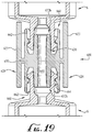
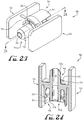
- Figures 19-21 show a syringe-to-syringe coupler 600 according to another example embodiment of the present invention.
- the coupler 600 is configured to removably engage two syringes S with threaded couplings.
- the coupler includes a hub 630 and fluid conduit 640 of similar size and shape as the previously described embodiment.
- the coupler also includes two coupling elements 660 comprising four clips 662 with threaded portions 664 similar to previously described couplers 400.
- the coupler 600 further includes two generally oppositely-positioned and outwardly offset planar members or gripping panels 620 attached to the outer surface of the coupling elements 660.
- the panels 620 are oriented on opposite sides of the cylindrical coupling elements such that the inner face of the panel 622 is oriented toward the length of the hub 630, for example such that the elongate extension of each of the panels 620 is generally oriented parallel with the extension of the hub 630.
- an exterior or outer surface 623 of one or both of the panels 620 can comprise one or more openings, indentations, recesses, protrusions or other texturizing or grip-enhancing surface features to provide a gripping surface for a user that is grasping the coupling 600, for example, by placement of one or more fingers against the outer surface 623 generally providing a squeezing-like action with two or more fingers.
- the panels are offset with respect to the length or extension of the hub 630, for example, such that the length of the panel 620 is not centered with the length of the hub 630, and thus causing one of the coupling elements 660 to extend beyond the end of the ends of the panels 420, for example, at a first end 412 of the coupler 400, and wherein another of the coupling elements 660 is generally positioned to be at least partially recessed below the ends of the panels 620 as is shown at the second end 614.
- the panels 620 can be positioned and oriented as desired with respect to the hub 630.
- the coupling 600 is generally similar to the coupling 400 as described above, for example, wherein the hubs 430, 630, the fluid conduits 440, 640, and the transverse flanges 450, 650 are substantially similar in size and functionality, and wherein the cylindrical outer body 620 is generally replaced with the oppositely-positioned and outwardly offset planar members 620 to define the coupling 600.
- one or more openings can be provided within one or more portions of the planar members 620 as desired, for example, which can be shaped and sized as desired.
- the hubs, fluid conduits and transverse flanges (and optional vents) generally remain similar to at least one of the embodiments as described above, or for example, such that an end (or one of the male tips) of the embodiments as described above is generally similar in size, shape and functionality.
- the panels 620 (and 720, 820, 920, 1020, 1120, 1220, and 1320, respectively) are generally similarly oppositely-positioned and outwardly offset with respect to the fluid conduit 640 (and 740, 840, 940, 1040, 1140, 1240 and 1340, respectively).
- Figures 22-24 show a syringe-to-syringe coupler 700 according to another example embodiment of the present invention.
- the coupler 700 is configured to removably engage a first syringe S with a slip-fit coupling and a second syringe with a threaded coupling 760.
- the coupler 700 includes a hub 730 and fluid conduit 740 of similar size and shape as the previously described embodiment.
- the coupler 700 includes a plurality of clips 762 760 comprising one or more clips 762 with threaded portions 764 and two gripping panels 720 similar to those described in the previous embodiment.
- the coupler 700 further includes a plurality of vents 766 positioned at the bottom of the coupling element 760.
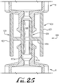
- Figures 25-27 show a syringe-to-syringe coupler 800 according to another example embodiment of the present invention.
- the coupler 800 is configured to engage two syringes S with a removable slip-fit coupling.
- the coupler 800 includes a hub 830 and fluid conduit 840 of similar size and shape as the previously described embodiment.
- the coupler 800 also includes two gripping panels 820 similar in size and shape to those described above. The gripping panels are attached to a flange 850 extending from a central portion of the hub 830.
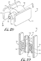
- Figures 28-30 show a syringe-to-syringe coupler 900 according to another example embodiment of the present invention.
- the coupler 900 is configured to removably engage a first syringe S with a slip-fit coupling and a second syringe with a threaded coupling.
- the coupler 900 includes a hub 930, fluid conduit 940, flange 950 and gripping panels 920 of similar size and shape as the previous embodiment.
- the coupler 900 also includes a single coupling element 960.
- the coupling element 960 includes a generally cylindrically shaped outer collar member or outer housing 962 surrounding a male tip 932 such that the inner sidewall of the outer housing is generally coaxially arranged with the male tip thereby forming an annular space therebetween.
- the inner sidewall of the outer housing 962 includes screw threads 964.
- the second syringe S is slip fitted onto the second male tip 932a.
- Figures 31-33 show a syringe-to-syringe coupler 1000 according to another example embodiment of the present invention.
- the coupler 1000 is configured to removably engage two syringes S with threaded couplings.
- the coupler 1000 includes a hub 1030, fluid conduit 1040, flange 1050 and gripping panels 1020 of similar size and shape as the previous embodiment.
- the coupler 1000 also includes two threaded coupling elements 1060 of similar size and shape of the coupling element in the previous embodiment. Each coupling element 1060 extends from the centrally positioned flange toward each respective male tip 1032.
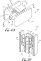
- Figures 34-36 show a syringe-to-syringe coupler 1100 according to another example embodiment of the present invention.
- the coupler 1100 is configured to removably engage a first syringe S with a slip-fit coupling and permanently engage a second syringe S with a removable coupling.
- the coupler 1100 includes a hub 1130, fluid conduit 1140, flange 1150 and gripping panels 1120 of similar size and shape as the previous embodiment.
- the coupler 1100 further includes two fingers or extensions 1124 extending from the inner face 1122 of each of the panels 1120.
- the extensions 1124 are configured for extending from the inner face 1122 (and generally at the same position with respect to each other) such that the rib R on the female connector FC of the syringe S can be removably engaged with an underside or angled surface 1125 of each of the extension 1124.
- the surfaces 1125 can be angled as desired, for example, to provide for appropriate removable engagement with the extensions 1124.
- only one of the inner surfaces 1122 of the coupling 1100 may include the extension 1124, for example, such that it is only one of the ribs R of the female connector FC that is engaging the single extension.
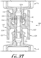
- Figure 37-39 show a syringe-to-syringe coupler 1200 according to another example embodiment of the present invention.
- the coupler 1200 is configured to removably engage a first syringe S with a slip-fit coupling and a second syringe S with a permanent coupling 1260.
- the coupler 1200 includes a hub 1230, fluid conduit 1240, flange 1250 and gripping panels 1220 of similar size and shape as the previous embodiment.
- the coupler 1200 includes the coupling element 1260, which generally functions substantially similar to the removable coupling elements comprising the four flexible clips.
- the coupling element 1260 includes four tab members or clips 1262 extending from the central flange 1250 that generally form a circular array at a distance from the hub 1230 generally extending from the center of the hub toward one of the male tips 1232.
- An internal portion or wall of at least one of the clips 1262 includes rib 1264.
- each of the four clips 1262 includes a rib 1264, for example, which remains in a substantially similar horizontal plane around the inner surfaces of each of the clips 1262.
- the female connector FC of each syringe S can be installed by pushing the snap connection provided by the split collar and the rib R.
- the clips are configured to prevent the female connector FC of the syringe S from being removed from the coupling element 1262.
- the coupler 1200 is permanently attached to the syringe S, for example, since rotation provides no axial movement as the rib 1264 is substantially horizontal.
- the flexibility of the clips 1262 are configured for little to no flexibility, for example, such that the permanent coupling 1260 provides for a one-way coupling action.
- the clips 1262 are configured for flexing just enough for the ribs R of the female connector FC to pass around the rib 1264, but the clips 1262 remain substantially rigid without much flexture such that the female connector FC remains substantially permanently coupled with the permanent connector 1260.
- the coupler 1200 further includes in the flange 1250 at the base of the coupling element 1260, which can comprise one or more vents 1266 extending through a portion of the flange 1250.
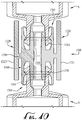
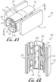
- Figure 40-42 show a syringe-to-syringe coupler 1300 according to another example embodiment of the present invention.
- the coupler 1300 is configured to removably engage two syringes S with threaded couplings.
- the coupler 1300 includes a hub 1330, fluid conduit 1240, flange 1350 and gripping panels 1320 of similar size and shape as the previous embodiment.
- the depicted embodiment includes two push fit coupling element 1360 similar to the previous embodiment.
- one of the ends of the male tips can be configured for engagement with a syringe fill pump.
- an end of the coupler can comprise a luer connector (e.g., luer lock or luer slip connector) for engagement with a tube set of the syringe fill pump, and the other end of the connector can be ENFit compatible for providing coupling engagement with an ENFit female connector FC.
- the tube set of the syringe fill pump can be modified to connect with ENFit compatible connectors, and thus, any of the couplers as described herein are capable of coupling a syringe to a tube set of a syringe fill pump (e.g., via the coupler).
- the oral administration coupling is formed from a substantially rigid material (> 700MPA as per the ISO standard).
- the coupling may be formed from a flexible, elastomeric material.
- the coupling can be formed from materials of one or more colors and/or may be at least partially translucent or clear, for example, such that the fluid or nutrients flowing therethrough are visible to the human eye.
- the coupling can be in the formed from light protecting materials, for example, reflecting or blocking UV or other wavelengths to reduce or eliminate damage to contents by light.
- the coupling may be provided as an accessory to a bottle or variable-volume container, for example, as disclosed in U.S. Patent Application Serial No. 13/191,721 , (Attorney Docket No. 2N 11.1-013).
- the coupling may be provided to facilitate transfer of fluids between the bottle and a syringe.
Landscapes
- Health & Medical Sciences (AREA)
- Pharmacology & Pharmacy (AREA)
- Life Sciences & Earth Sciences (AREA)
- Animal Behavior & Ethology (AREA)
- General Health & Medical Sciences (AREA)
- Public Health (AREA)
- Veterinary Medicine (AREA)
- Physics & Mathematics (AREA)
- Fluid Mechanics (AREA)
- Infusion, Injection, And Reservoir Apparatuses (AREA)
Claims (15)
- Couplage (1) destiné à transférer des fluides entre au moins deux connecteurs femelles, le couplage (1) comprenant :un noyau à embout mâle (30) s'étendant d'une première extrémité à une seconde extrémité, lesdites extrémités étant au moins en partie coniques ;une collerette en position centrale (50) s'étendant vers l'extérieur depuis le noyau à embout mâle (30) ;un conduit de distribution de fluide (40) s'étendant à travers le noyau de la première extrémité à la seconde extrémité ; etun corps (20) couplé à la collerette (50) de sorte que le corps (20) soit décalé vers l'extérieur depuis le noyau à embout mâle (30) ;dans lequel une première partie du corps (20) est en prise avec la collerette (50) et s'étend en direction de la première extrémité du noyau à embout mâle (30) et une seconde partie du corps (20) est en prise avec la collerette (50) et s'étend en direction de la seconde extrémité du noyau à embout mâle (30).
- Couplage (1) selon la revendication 1, dans lequel :(a) la collerette (50) comprend un réseau radial de nervures espacées ;(b) le corps(20) comprend des encoches formées dessus destinées à faciliter sa prise ; ou(c) le couplage (1) est conçu pour produire un raccord non fileté par emboîtement avec une seringue.
- Couplage (1) selon la revendication 1, dans lequel le corps (20) présente la forme d'un élément collier externe et comprend des filets formés sur une partie intérieure de celui-ci, facultativement dans lequel le couplage (1) est conçu pour produire (a) un raccord fileté avec une seringue ; ou (b) une combinaison d'un raccord non fileté par emboîtement avec une première seringue et d'un raccord fileté avec une seconde seringue.
- Couplage (1) selon la revendication 1, comprenant en outre au moins un organe de prise positionné entre le noyau à embout mâle (30) et le corps (20) destiné à produire une prise avec une seringue.
- Couplage (1) selon la revendication 4, dans lequel l'au moins un organe de prise comprend une pince comportant une nervure s'étendant à partir d'une surface interne de ladite pince.
- Couplage (1) selon la revendication 4, dans lequel l'au moins un organe de prise comprend un réseau radial de quatre pinces décalées vers l'extérieur à partir du noyau à embout mâle (30).
- Couplage (1) selon la revendication 6, dans lequel au moins l'une des quatre pinces comprend une nervure s'étendant à partir d'une surface interne de ladite pince ; facultativement dans lequel la nervure s'étend le long (a) d'un trajet en hélice pour produire une prise amovible avec au moins l'une des seringues ; ou (b) d'un trajet horizontal pour produire une prise permanente avec au moins l'une des seringues.
- Couplage (1) selon la revendication 1, dans lequel l'une des première ou seconde extrémités du noyau présente la forme d'un connecteur Luer pour un raccord avec un ensemble de tubes d'une pompe de remplissage de seringue, et dans lequel l'autre des extrémités présente la forme d'un connecteur pour un raccord avec un connecteur femelle d'une seringue.
- Couplage (1) selon la revendication 1, dans lequel au moins une partie du conduit de distribution de fluide comprend un espace d'amorçage compris entre environ 0,01 millilitre et environ 0,20 millilitre ;
facultativement dans lequel l'espace d'amorçage est généralement compris (a) entre environ 0,04 millilitre et environ 0,12 millilitre ; ou (b) entre environ 0,04691 millilitre et environ 0,09382 millilitre. - Couplage (1) selon la revendication 1, dans lequel le corps (20) comprend deux éléments généralement planaires positionnés de façon opposée et décalés vers l'extérieur à partir du noyau.
- Couplage (1) selon la revendication 10, dans lequel les éléments planaires sont de forme généralement rectangulaire.
- Couplage (1) selon la revendication 10, dans lequel la collerette (50) raccorde de manière généralement fixe le noyau en position centrale aux éléments planaires positionnés de façon opposée.
- Couplage (1) selon la revendication 12, dans lequel la collerette (50) vient partiellement en prise avec au moins une partie périphérique externe du noyau en position centrale et s'étend à l'opposé et vers l'extérieur pour venir en prise avec une partie de chacun des éléments planaires.
- Couplage (1) selon la revendication 13, comprenant en outre au moins un organe de prise positionné entre le noyau en position centrale et le corps (20) pour produire une prise avec le connecteur femelle d'au moins l'une des seringues ; facultativement dans lequel l'au moins un organe de prise comprend (a) une pince comportant une nervure s'étendant à partir d'une surface interne de ladite pince ; ou (b) un élément collier comprenant des filets formés sur une partie interne de celui-ci, et dans lequel les filets sont conçus pour une prise amovible avec la ou les pattes du connecteur femelle d'au moins l'une des seringues.
- Couplage (1) selon la revendication 13, comprenant en outre au moins un organe de prise s'étendant à partir d'une surface interne d'au moins l'un des éléments planaires pour produire une prise avec la ou les pattes du connecteur femelle d'au moins l'une des seringues.
Applications Claiming Priority (2)
| Application Number | Priority Date | Filing Date | Title |
|---|---|---|---|
| US201562181595P | 2015-06-18 | 2015-06-18 | |
| PCT/US2016/038051 WO2016205626A1 (fr) | 2015-06-18 | 2016-06-17 | Système de couplage seringue-à-seringue avec embout mâle |
Publications (2)
| Publication Number | Publication Date |
|---|---|
| EP3310322A1 EP3310322A1 (fr) | 2018-04-25 |
| EP3310322B1 true EP3310322B1 (fr) | 2020-06-03 |
Family
ID=56413839
Family Applications (1)
| Application Number | Title | Priority Date | Filing Date |
|---|---|---|---|
| EP16739290.1A Active EP3310322B1 (fr) | 2015-06-18 | 2016-06-17 | Système de couplage seringue-à-seringue avec embout mâle |
Country Status (3)
| Country | Link |
|---|---|
| US (2) | US10576020B2 (fr) |
| EP (1) | EP3310322B1 (fr) |
| WO (1) | WO2016205626A1 (fr) |
Families Citing this family (73)
| Publication number | Priority date | Publication date | Assignee | Title |
|---|---|---|---|---|
| US8864707B1 (en) | 2010-12-03 | 2014-10-21 | Medical Device Engineering, LLC. | Tamper indicating closure assembly |
| USD1010114S1 (en) * | 2013-03-13 | 2024-01-02 | Joseph P. Schultz | Medical connector contamination prevention device |
| WO2015019343A1 (fr) | 2013-08-07 | 2015-02-12 | Medimop Medical Projects Ltd | Dispositif de transfert de liquide utilisable pour des contenants de liquide pour perfusion |
| US10912898B1 (en) | 2014-02-03 | 2021-02-09 | Medical Device Engineering Llc | Tamper evident cap for medical fitting |
| US10207099B1 (en) | 2014-02-21 | 2019-02-19 | Patrick Vitello | Closure assembly for medical fitting |
| US10166347B1 (en) | 2014-07-18 | 2019-01-01 | Patrick Vitello | Closure assembly for a medical device |
| US10773067B2 (en) | 2014-09-08 | 2020-09-15 | Neomed, Inc. | Enteral connectors having coupling features |
| USD802743S1 (en) | 2014-12-08 | 2017-11-14 | Neomed, Inc. | Fluid transfer lid |
| US10300263B1 (en) | 2015-02-27 | 2019-05-28 | Timothy Brandon Hunt | Closure assembly for a medical connector |
| USD831204S1 (en) | 2015-03-02 | 2018-10-16 | Neomed, Inc. | Enteral syringe |
| USD831203S1 (en) | 2015-03-02 | 2018-10-16 | Neomed, Inc. | Enteral syringe |
| US10166343B1 (en) | 2015-03-13 | 2019-01-01 | Timothy Brandon Hunt | Noise evident tamper cap |
| US10315024B1 (en) | 2015-03-19 | 2019-06-11 | Patick Vitello | Torque limiting closure assembly |
| WO2016154304A1 (fr) | 2015-03-24 | 2016-09-29 | Neomed, Inc. | Coupleur de fluide d'administration orale |
| US10624817B2 (en) | 2015-03-24 | 2020-04-21 | Neomed, Inc. | Oral administration coupler for back-of-mouth delivery |
| WO2016205626A1 (fr) * | 2015-06-18 | 2016-12-22 | Neomed, Inc. | Système de couplage seringue-à-seringue avec embout mâle |
| USD825746S1 (en) | 2015-06-18 | 2018-08-14 | Neomed, Inc. | Syringe-to-syringe coupler |
| BR112018000752A2 (pt) | 2015-07-14 | 2018-09-04 | Neomed Inc | engate de controle de dosagem enteral, dispositivo de fluido enteral, seringa enteral, ponta de extensão do lúmen, e dispositivo de distribuição de fluido |
| US10682287B2 (en) | 2015-07-14 | 2020-06-16 | Neomed, Inc. | Dosing control coupling for enteral fluid transfer and enteral couplings and syringes |
| CA2992500C (fr) | 2015-07-15 | 2021-07-06 | Neomed, Inc. | Raccords d'adaptation enteraux |
| US10940086B2 (en) * | 2015-11-12 | 2021-03-09 | Scalpal Llc | Bottle support and protective collar |
| EP3419582B1 (fr) | 2016-02-24 | 2022-07-13 | Avent, Inc. | Raccord de transfert de fluide |
| US11166876B2 (en) | 2016-02-24 | 2021-11-09 | Neomed, Inc. | Fluid transfer connector |
| IL245800A0 (en) * | 2016-05-24 | 2016-08-31 | West Pharma Services Il Ltd | A device with two vial adapters includes two identical vial adapters |
| IL245803A0 (en) | 2016-05-24 | 2016-08-31 | West Pharma Services Il Ltd | Devices with two vial adapters include an aerated drug vial adapter and an aerated liquid vial adapter |
| IL246073A0 (en) | 2016-06-06 | 2016-08-31 | West Pharma Services Il Ltd | A fluid transport device for use with a slide-driven piston medicine pump cartridge |
| EP3266496B1 (fr) * | 2016-07-08 | 2021-04-14 | Fenwal, Inc. | Adaptateur pour connecteurs médicaux |
| EP3487576B1 (fr) * | 2016-07-25 | 2021-06-02 | Neomed, Inc. | Couplage de commande de dosage pour transfert de liquide entéral et raccords et seringues entéraux |
| USD816228S1 (en) * | 2016-07-26 | 2018-04-24 | C. R. Bard, Inc. | Vascular access port stem |
| IL247376A0 (en) | 2016-08-21 | 2016-12-29 | Medimop Medical Projects Ltd | Injector assembly |
| USD833006S1 (en) * | 2016-11-28 | 2018-11-06 | Neomed, Inc. | Fluid transfer connector |
| IL249408A0 (en) | 2016-12-06 | 2017-03-30 | Medimop Medical Projects Ltd | A device for transporting fluids for use with an infusion fluid container and a hand tool similar to a plunger to release a vial from it |
| US10307548B1 (en) | 2016-12-14 | 2019-06-04 | Timothy Brandon Hunt | Tracking system and method for medical devices |
| US11097071B1 (en) | 2016-12-14 | 2021-08-24 | International Medical Industries Inc. | Tamper evident assembly |
| US10953162B1 (en) | 2016-12-28 | 2021-03-23 | Timothy Brandon Hunt | Tamper evident closure assembly |
| US10758684B1 (en) | 2017-03-03 | 2020-09-01 | Jonathan J. Vitello | Tamper evident assembly |
| IL251458A0 (en) | 2017-03-29 | 2017-06-29 | Medimop Medical Projects Ltd | Liquid drug delivery devices are user-operated for use in pre-prepared liquid drug delivery assemblies (rtu) |
| US11040149B1 (en) | 2017-03-30 | 2021-06-22 | International Medical Industries | Tamper evident closure assembly for a medical device |
| US10888672B1 (en) | 2017-04-06 | 2021-01-12 | International Medical Industries, Inc. | Tamper evident closure assembly for a medical device |
| US10898659B1 (en) | 2017-05-19 | 2021-01-26 | International Medical Industries Inc. | System for handling and dispensing a plurality of products |
| US10933202B1 (en) | 2017-05-19 | 2021-03-02 | International Medical Industries Inc. | Indicator member of low strength resistance for a tamper evident closure |
| IL254802A0 (en) | 2017-09-29 | 2017-12-31 | Medimop Medical Projects Ltd | A device with two vial adapters includes two identical perforated vial adapters |
| EP3691740A1 (fr) * | 2017-10-06 | 2020-08-12 | Neomed, Inc. | Raccordement mâle-femelle |
| US11541180B1 (en) | 2017-12-21 | 2023-01-03 | Patrick Vitello | Closure assembly having a snap-fit construction |
| US11413220B2 (en) | 2018-01-23 | 2022-08-16 | Avent, Inc. | Vented air release coupling and method of using the same |
| US11278681B1 (en) | 2018-02-20 | 2022-03-22 | Robert Banik | Tamper evident adaptor closure |
| WO2019169090A1 (fr) * | 2018-03-01 | 2019-09-06 | Neomed, Inc. | Coupleur pour nettoyer un embout de tube d'alimentation |
| US11413406B1 (en) | 2018-03-05 | 2022-08-16 | Jonathan J. Vitello | Tamper evident assembly |
| US11857751B1 (en) | 2018-07-02 | 2024-01-02 | International Medical Industries Inc. | Assembly for a medical connector |
| US11779520B1 (en) | 2018-07-02 | 2023-10-10 | Patrick Vitello | Closure for a medical dispenser including a one-piece tip cap |
| US11793987B1 (en) | 2018-07-02 | 2023-10-24 | Patrick Vitello | Flex tec closure assembly for a medical dispenser |
| JP1630477S (fr) | 2018-07-06 | 2019-05-07 | ||
| JP7334888B2 (ja) * | 2018-07-13 | 2023-08-29 | 武田薬品工業株式会社 | メス-メスアダプタ |
| US11690994B1 (en) * | 2018-07-13 | 2023-07-04 | Robert Banik | Modular medical connector |
| US11426328B1 (en) | 2018-08-31 | 2022-08-30 | Alexander Ollmann | Closure for a medical container |
| USD948713S1 (en) | 2019-09-03 | 2022-04-12 | International Medical Industries, Inc. | Asymmetrical self righting tip cap |
| US11471610B1 (en) | 2018-10-18 | 2022-10-18 | Robert Banik | Asymmetrical closure for a medical device |
| USD914876S1 (en) * | 2018-11-06 | 2021-03-30 | Nipro Corporation | Cap for syringe |
| USD903865S1 (en) | 2018-11-19 | 2020-12-01 | International Medical Industries, Inc. | Self-righting tip cap |
| USD923812S1 (en) | 2019-01-16 | 2021-06-29 | West Pharma. Services IL, Ltd. | Medication mixing apparatus |
| JP1648075S (fr) | 2019-01-17 | 2019-12-16 | ||
| ES2946032T3 (es) | 2019-01-31 | 2023-07-12 | West Pharma Services Il Ltd | Dispositivo de transferencia de líquido |
| PT3781113T (pt) | 2019-04-30 | 2024-05-02 | West Pharma Services Il Ltd | Dispositivo de transferência de líquido com espigão iv de duplo lúmen |
| US11911339B1 (en) | 2019-08-15 | 2024-02-27 | Peter Lehel | Universal additive port cap |
| US11697527B1 (en) | 2019-09-11 | 2023-07-11 | Logan Hendren | Tamper evident closure assembly |
| US11357588B1 (en) | 2019-11-25 | 2022-06-14 | Patrick Vitello | Needle packaging and disposal assembly |
| US11904149B1 (en) | 2020-02-18 | 2024-02-20 | Jonathan Vitello | Oral tamper evident closure with retained indicator |
| USD956958S1 (en) | 2020-07-13 | 2022-07-05 | West Pharma. Services IL, Ltd. | Liquid transfer device |
| RU202064U1 (ru) * | 2020-07-27 | 2021-01-28 | Общество С Ограниченной Ответственностью Химикофармацевтический Концерн "Медполимер" | Двухсторонняя канюля для смешивания |
| US11523970B1 (en) | 2020-08-28 | 2022-12-13 | Jonathan Vitello | Tamper evident shield |
| US12070591B1 (en) | 2020-12-14 | 2024-08-27 | Patrick Vitello | Snap action tamper evident closure assembly |
| US11872187B1 (en) | 2020-12-28 | 2024-01-16 | Jonathan Vitello | Tamper evident seal for a vial cover |
| US11903902B2 (en) | 2022-01-03 | 2024-02-20 | Benjamin Martin DAVIS | Fluid transfer couplings |
Family Cites Families (113)
| Publication number | Priority date | Publication date | Assignee | Title |
|---|---|---|---|---|
| DE7740288U1 (fr) | 1978-05-24 | Templin, Gernot, 6000 Frankfurt | ||
| DE731065C (de) | 1937-08-13 | 1943-02-01 | Krupp Fried Grusonwerk Ag | Verfahren und Vorrichtung zum Entwaessern von Schlaemmen von Mineralien und sonstigen Stoffen |
| US2477598A (en) | 1948-02-16 | 1949-08-02 | George M Hain | Microworker for lubricating greases |
| US3473833A (en) | 1967-12-28 | 1969-10-21 | Nat Distillers Chem Corp | Plastic pipe coupling |
| US3572337A (en) | 1968-12-26 | 1971-03-23 | George J Schunk | Syringe for oral administration of medicine |
| US4046145A (en) | 1976-06-29 | 1977-09-06 | American Hospital Supply Corporation | Syringe connector |
| DE8613738U1 (de) | 1986-05-21 | 1986-07-10 | Bremi Auto-Elektrik Bremicker GmbH + Co, 5883 Kierspe | Montagewerkzeug für Kabel |
| US4685173A (en) | 1986-07-07 | 1987-08-11 | Chrysler Motors Corporation | Grommet with angularly positionable tubular portion |
| US4743229A (en) | 1986-09-29 | 1988-05-10 | Collagen Corporation | Collagen/mineral mixing device and method |
| USD303710S (en) | 1986-12-29 | 1989-09-26 | Kontes Glass Company | Connector for joining laboratory glassware |
| US4842592A (en) | 1987-05-06 | 1989-06-27 | Teleflex Incorporated | Connector assembly |
| USD327318S (en) | 1989-10-10 | 1992-06-23 | Baxter International Inc. | Locking cannula |
| CA2086677A1 (fr) | 1990-07-06 | 1992-01-07 | Martyn Neil Jones | Dispositif d'administration orale d'un liquide |
| US5224937A (en) | 1991-06-21 | 1993-07-06 | Npbi Nederlands Produktielaboratorium Voor Bloedtransfusieapparatuur En Infusievloeistoffen B.V. | Closed syringe-filling system |
| US5405339A (en) | 1993-09-03 | 1995-04-11 | Medtronic, Inc. | Medical connector and method for connecting medical tubing |
| USD395502S (en) | 1996-03-19 | 1998-06-23 | Mcgaw, Inc. | Catheter plug |
| USD398060S (en) | 1997-03-13 | 1998-09-08 | Brown Daniel G | Pulmonary filter |
| US5957166A (en) | 1997-06-16 | 1999-09-28 | Fusion Medical Technologies, Inc. | Method and apparatus for dispersing fluid into a material |
| DE69839128T2 (de) | 1997-12-19 | 2009-03-05 | United States Surgical Corporation, Norwalk | Spenderanordnung |
| CA2262477C (fr) | 1998-05-16 | 2008-02-12 | Bracco International B.V. | Fermeture polyvalente universelle |
| US6726672B1 (en) * | 1998-09-28 | 2004-04-27 | Icu Medical, Inc. | Intravenous drug access system |
| USD435652S (en) | 1999-03-30 | 2000-12-26 | Alcon Laboratories, Inc. | Shielded female connector |
| US6126679A (en) | 1999-04-12 | 2000-10-03 | Botts; Lynne Marie | Nipple for use with liquid and medicine dispensing bottle |
| US7799009B2 (en) * | 2000-01-24 | 2010-09-21 | Bracco Diagnostics Inc. | Tabletop drug dispensing vial access adapter |
| US6592251B2 (en) | 2001-01-26 | 2003-07-15 | Howmedica Osteonics Corp. | Cement mixing and dispensing device |
| US7172085B2 (en) | 2001-12-04 | 2007-02-06 | Beaudette Susan A | Squeezable, fillable feeding device |
| US7118539B2 (en) | 2002-02-26 | 2006-10-10 | Scimed Life Systems, Inc. | Articulating guide wire for embolic protection and methods of use |
| USD473647S1 (en) | 2002-03-26 | 2003-04-22 | Becton, Dickinson And Company | Adaptor for point of care testing cartridge |
| USD534796S1 (en) | 2002-08-02 | 2007-01-09 | Falkenburg Charles W | Bottle coupling device |
| US7135027B2 (en) | 2002-10-04 | 2006-11-14 | Baxter International, Inc. | Devices and methods for mixing and extruding medically useful compositions |
| DE20302788U1 (de) | 2003-02-20 | 2004-06-24 | Nietzke, Mathias | Leckagesicher transportierbare Infusionsgeräte und dafür geeignete Einstechdorne |
| US7914502B2 (en) | 2003-07-31 | 2011-03-29 | Nypro Inc. | Anti-drawback medical valve |
| FR2858931B1 (fr) | 2003-08-21 | 2007-04-13 | Becton Dickinson France | Dispositif d'administration orale d'un medicament |
| FR2863162B1 (fr) | 2003-12-05 | 2006-12-08 | Vygon | Raccords males et raccords femelles pour realiser des connexions de transmission de liquide, notamment pour des lignes de nutrition enterale |
| HK1077154A2 (en) | 2003-12-30 | 2006-02-03 | Vasogen Ireland Ltd | Valve assembly |
| US20050209555A1 (en) | 2004-03-18 | 2005-09-22 | Lance Middleton | Systems and methods for mixing fluids |
| US7523967B2 (en) | 2004-12-13 | 2009-04-28 | Alcon, Inc. | Tubing fitting |
| US8328768B2 (en) | 2005-02-11 | 2012-12-11 | Angiodynamics, Inc | Pressure activated safety valve with improved flow characteristics and durability |
| US7740288B2 (en) | 2005-05-09 | 2010-06-22 | Northgate Technologies Inc. | High-flow luer lock connector for a luer lock connection |
| DE102005030510A1 (de) * | 2005-06-30 | 2007-01-18 | Beller, Klaus-Dieter, Dipl.-Ing. Dr. med. | Spritzenadapter für sichere Verbindung von Spritzen ungleicher Bauart |
| US7998134B2 (en) | 2007-05-16 | 2011-08-16 | Icu Medical, Inc. | Medical connector |
| ITTO20050515A1 (it) | 2005-07-25 | 2007-01-26 | Borla Ind | Connettore valvolare medicale |
| US7985205B2 (en) | 2005-09-14 | 2011-07-26 | Boston Scientific Scimed, Inc. | Medical catheter external bolster having strain relief member |
| US7503905B2 (en) | 2005-10-03 | 2009-03-17 | Ultradent Products, Inc. | Venting syringe plunger |
| EP1931414A4 (fr) | 2005-10-05 | 2016-02-17 | Acu Rate Pty Ltd | Ensemble de gestion d'ecoulement regule |
| US8852167B2 (en) | 2005-12-01 | 2014-10-07 | Bayer Medical Care Inc. | Medical connector |
| FR2894150B1 (fr) | 2005-12-05 | 2008-01-04 | Ace Dev Solution Soc A Respons | Connecteur a usage medical |
| JP2009533144A (ja) | 2006-04-11 | 2009-09-17 | ナイプロ インコーポレイテッド | 移動部材を有する医療弁および方法 |
| CA2548976A1 (fr) | 2006-06-01 | 2007-12-01 | Paolo Anzivino | Tetine administrant un medicament |
| EP2086623B1 (fr) | 2006-10-25 | 2011-04-27 | ICU Medical, Inc. | Connecteur médical |
| US20080183153A1 (en) | 2007-01-31 | 2008-07-31 | Benlan, Inc. | Enteral Feeding Tube Connector |
| US7811278B2 (en) | 2007-02-11 | 2010-10-12 | Cuffco, Llc | Fluid connector |
| US8034033B2 (en) | 2007-04-13 | 2011-10-11 | Yair Grinberg | Hypodermic syringe with vial attachment |
| USD588693S1 (en) | 2007-06-12 | 2009-03-17 | Nordson Corporation | Liquid dispensing syringe |
| US20080312640A1 (en) | 2007-06-14 | 2008-12-18 | Sabin Corporation | Modified luer fittings for feeding tube adapter |
| US7594681B2 (en) | 2007-07-19 | 2009-09-29 | Tyco Healthcare Group Lp | Fluid line coupling |
| CN101835434A (zh) | 2007-08-29 | 2010-09-15 | 埃泰克斯公司 | 骨水泥混合和递送系统及其应用方法 |
| SE531600C2 (sv) * | 2007-10-10 | 2009-06-02 | Ortoviva Ab | Blandsystem och blandningsförfarande för medicinska ändamål |
| US20100022951A1 (en) | 2008-05-19 | 2010-01-28 | Luce, Forward, Hamilton 7 Scripps, Llp | Detachable hub/luer device and processes |
| ATE526933T1 (de) * | 2008-01-17 | 2011-10-15 | Teva Medical Ltd | Spritzenadapterelement in einem arznei- mischsystem |
| US8343041B2 (en) | 2008-05-19 | 2013-01-01 | Boston Scientific Scimed, Inc. | Integrated locking device with passive sealing |
| FR2930428B1 (fr) | 2008-04-25 | 2011-12-23 | Plastef Investissements | Dispositif de pipette a securite |
| JP4743229B2 (ja) | 2008-05-29 | 2011-08-10 | 国立大学法人東北大学 | 中性粒子を用いた半導体装置の成膜方法 |
| US8551068B2 (en) | 2008-08-22 | 2013-10-08 | Circle Biologics, Inc. | Fluid management devices and methods |
| EP2322132B1 (fr) | 2008-09-05 | 2016-07-13 | OncoTherapy Science Inc | Dispositif et procédé pour préparer automatiquement un médicament en émulsion |
| USD644618S1 (en) | 2008-10-01 | 2011-09-06 | Aqua Science Corporation | Nozzle for cleaning substrate |
| US8679090B2 (en) | 2008-12-19 | 2014-03-25 | Icu Medical, Inc. | Medical connector with closeable luer connector |
| US8182452B2 (en) | 2009-04-06 | 2012-05-22 | Carefusion 303, Inc. | Closed male luer device for use with needleless access devices |
| US7955317B2 (en) | 2009-06-30 | 2011-06-07 | Tyco Healthcare Group Lp | Female adaptor for feeding line |
| US10711930B2 (en) * | 2009-12-09 | 2020-07-14 | Nordson Corporation | Releasable connection assembly |
| US9388929B2 (en) * | 2009-12-09 | 2016-07-12 | Nordson Corporation | Male bayonet connector |
| US9433562B2 (en) | 2010-07-27 | 2016-09-06 | Neomed, Inc. | System for aseptic collection and enteral delivery |
| US8303571B2 (en) | 2010-07-30 | 2012-11-06 | Errorless Medical, Llc | Multiple-line connective devices for infusing medication |
| US9814870B2 (en) | 2010-08-17 | 2017-11-14 | Becton, Dickinson And Company | Non-luer connectors |
| US9017295B2 (en) | 2010-09-02 | 2015-04-28 | Skill Partner Limited | Syringe adapter with a ball-typed valve |
| US9078809B2 (en) * | 2011-06-16 | 2015-07-14 | Crisi Medical Systems, Inc. | Medication dose preparation and transfer system |
| USD712025S1 (en) | 2011-06-28 | 2014-08-26 | Daikyo Seiko, Ltd. | Syringe barrel |
| USD691261S1 (en) | 2011-06-28 | 2013-10-08 | Daikyo Seiko, Ltd. | Nozzle cap for syringe |
| ES2664517T3 (es) | 2011-09-09 | 2018-04-19 | Icu Medical, Inc. | Conectores médicos con interfaces de acoplamiento resistentes a fluidos |
| US20130098861A1 (en) | 2011-10-19 | 2013-04-25 | Neomed, Inc. | Fluid containment sytem with nipple adapter |
| WO2013081699A2 (fr) | 2011-11-28 | 2013-06-06 | Neomed, Inc. | Couplage entéral femelle |
| WO2013088439A1 (fr) | 2011-12-13 | 2013-06-20 | Oridion Medical 1987 Ltd. | Raccords luer |
| PT2900301T (pt) | 2012-09-26 | 2016-11-08 | Transcoject Gmbh | Seringa pré-cheia |
| EP2916905A4 (fr) | 2012-11-12 | 2016-11-09 | Icu Medical Inc | Raccord médical |
| USD714935S1 (en) | 2013-01-10 | 2014-10-07 | Fuso Pharmaeutical Industries, Ltd. | Adapter for connecting a needle to a syringe |
| USD731065S1 (en) | 2013-03-08 | 2015-06-02 | Covidien Lp | EVQ pressure sensor filter of an exhalation module |
| US9974941B2 (en) | 2013-03-13 | 2018-05-22 | Joseph P. Schultz | Medical connector contamination prevention systems |
| US8708976B1 (en) | 2013-03-14 | 2014-04-29 | Carefusion 303, Inc. | Needleless connector with a tortuous fluid flow path |
| US20140323995A1 (en) | 2013-04-24 | 2014-10-30 | Transcend Medical, Inc. | Targeted Drug Delivery Devices and Methods |
| JP2015051092A (ja) * | 2013-09-06 | 2015-03-19 | 株式会社ジェイ・エム・エス | ダブルオスコネクタ |
| USD716638S1 (en) | 2013-11-26 | 2014-11-04 | Curt McDonald | Rebar cap |
| USD756200S1 (en) | 2013-11-26 | 2016-05-17 | Curt McDonald | Rebar cap |
| USD736914S1 (en) | 2014-01-29 | 2015-08-18 | Joseph P. Schultz | Shielded medical connector |
| USD737962S1 (en) | 2014-01-29 | 2015-09-01 | Joseph P. Schultz | Medical connector with spiral guard |
| USD736915S1 (en) | 2014-01-29 | 2015-08-18 | Joseph P. Schultz | Double shielded medical connector |
| US20150238747A1 (en) | 2014-02-24 | 2015-08-27 | Dale Medical Products, Inc. | Connector with non-luer compatible access ports' |
| US9149623B1 (en) | 2014-03-18 | 2015-10-06 | Oridion Medical 1987 Ltd. | Adapters |
| WO2016019138A1 (fr) | 2014-07-30 | 2016-02-04 | Covidien Lp | Raccord aéré pour seringue d'alimentation |
| US11027901B2 (en) | 2014-09-08 | 2021-06-08 | Neomed, Inc. | Transfer lid |
| WO2016040126A1 (fr) | 2014-09-08 | 2016-03-17 | Neomed, Inc. | Capuchon de pointe à auto-redressement |
| WO2016040127A1 (fr) | 2014-09-08 | 2016-03-17 | Neomed, Inc. | Connecteur aéré pour récipients de fluide médical |
| US10688251B2 (en) | 2014-09-08 | 2020-06-23 | Neomed, Inc. | Self-righting tip cap |
| US10173044B2 (en) | 2014-09-19 | 2019-01-08 | TA Instruments—Waters L.L.C. | Locking taper fluid connection interfaces |
| US10071234B2 (en) | 2014-11-25 | 2018-09-11 | Avent, Inc. | Dual material Y-connector |
| WO2016089869A1 (fr) | 2014-12-02 | 2016-06-09 | Covidien Lp | Ensemble adaptateur pour alimentation entérique et procédé de fabrication |
| US9926185B2 (en) | 2014-12-08 | 2018-03-27 | Neomed, Inc. | Fluid transfer lid |
| US10420925B2 (en) | 2015-01-20 | 2019-09-24 | Oridion Medical 1987 Ltd. | Adapter |
| WO2016154304A1 (fr) | 2015-03-24 | 2016-09-29 | Neomed, Inc. | Coupleur de fluide d'administration orale |
| WO2016205626A1 (fr) | 2015-06-18 | 2016-12-22 | Neomed, Inc. | Système de couplage seringue-à-seringue avec embout mâle |
| BR112018000752A2 (pt) | 2015-07-14 | 2018-09-04 | Neomed Inc | engate de controle de dosagem enteral, dispositivo de fluido enteral, seringa enteral, ponta de extensão do lúmen, e dispositivo de distribuição de fluido |
| EP3419582B1 (fr) | 2016-02-24 | 2022-07-13 | Avent, Inc. | Raccord de transfert de fluide |
| EP3487576B1 (fr) | 2016-07-25 | 2021-06-02 | Neomed, Inc. | Couplage de commande de dosage pour transfert de liquide entéral et raccords et seringues entéraux |
| JP1743229S (ja) | 2022-07-27 | 2023-05-01 | 車両用カバーパネル |
-
2016
- 2016-06-17 WO PCT/US2016/038051 patent/WO2016205626A1/fr active Application Filing
- 2016-06-17 EP EP16739290.1A patent/EP3310322B1/fr active Active
- 2016-06-17 US US15/185,583 patent/US10576020B2/en active Active
-
2019
- 2019-08-23 US US16/548,969 patent/US11065181B2/en active Active
Non-Patent Citations (1)
| Title |
|---|
| None * |
Also Published As
| Publication number | Publication date |
|---|---|
| US20200038291A1 (en) | 2020-02-06 |
| US10576020B2 (en) | 2020-03-03 |
| US11065181B2 (en) | 2021-07-20 |
| US20160367439A1 (en) | 2016-12-22 |
| WO2016205626A1 (fr) | 2016-12-22 |
| EP3310322A1 (fr) | 2018-04-25 |
Similar Documents
| Publication | Publication Date | Title |
|---|---|---|
| US11065181B2 (en) | Syringe-to-syringe coupler | |
| US10773067B2 (en) | Enteral connectors having coupling features | |
| US11986617B2 (en) | Vented connector for medical fluid vessels | |
| EP3273927B1 (fr) | Coupleur de liquide pour administration orale | |
| US10307337B2 (en) | Oral administration coupler for back-of-mouth delivery | |
| EP3424554B1 (fr) | Accouplements d'adaptateur entéral | |
| US10004889B2 (en) | Enteral feeding connector and assembly | |
| US20090326481A1 (en) | Discriminating oral-tip adaptor | |
| AU2017301621A1 (en) | Dosing control coupling for enteral fluid transfer and enteral couplings and syringes | |
| WO2016200857A1 (fr) | Ensemble seringue d'alimentation entérale | |
| US20190192843A1 (en) | Coupler for cleaning a feeding tube hub | |
| AU2018231125A1 (en) | Enteral connectors having coupling features | |
| EP3484433A1 (fr) | Coupleur d'administration par voie orale pour administration de la bouche |
Legal Events
| Date | Code | Title | Description |
|---|---|---|---|
| STAA | Information on the status of an ep patent application or granted ep patent |
Free format text: STATUS: THE INTERNATIONAL PUBLICATION HAS BEEN MADE |
|
| PUAI | Public reference made under article 153(3) epc to a published international application that has entered the european phase |
Free format text: ORIGINAL CODE: 0009012 |
|
| STAA | Information on the status of an ep patent application or granted ep patent |
Free format text: STATUS: REQUEST FOR EXAMINATION WAS MADE |
|
| 17P | Request for examination filed |
Effective date: 20180115 |
|
| AK | Designated contracting states |
Kind code of ref document: A1 Designated state(s): AL AT BE BG CH CY CZ DE DK EE ES FI FR GB GR HR HU IE IS IT LI LT LU LV MC MK MT NL NO PL PT RO RS SE SI SK SM TR |
|
| AX | Request for extension of the european patent |
Extension state: BA ME |
|
| DAV | Request for validation of the european patent (deleted) | ||
| DAX | Request for extension of the european patent (deleted) | ||
| GRAP | Despatch of communication of intention to grant a patent |
Free format text: ORIGINAL CODE: EPIDOSNIGR1 |
|
| STAA | Information on the status of an ep patent application or granted ep patent |
Free format text: STATUS: GRANT OF PATENT IS INTENDED |
|
| INTG | Intention to grant announced |
Effective date: 20181218 |
|
| GRAJ | Information related to disapproval of communication of intention to grant by the applicant or resumption of examination proceedings by the epo deleted |
Free format text: ORIGINAL CODE: EPIDOSDIGR1 |
|
| STAA | Information on the status of an ep patent application or granted ep patent |
Free format text: STATUS: REQUEST FOR EXAMINATION WAS MADE |
|
| STAA | Information on the status of an ep patent application or granted ep patent |
Free format text: STATUS: EXAMINATION IS IN PROGRESS |
|
| INTC | Intention to grant announced (deleted) | ||
| 17Q | First examination report despatched |
Effective date: 20190524 |
|
| GRAP | Despatch of communication of intention to grant a patent |
Free format text: ORIGINAL CODE: EPIDOSNIGR1 |
|
| STAA | Information on the status of an ep patent application or granted ep patent |
Free format text: STATUS: GRANT OF PATENT IS INTENDED |
|
| INTG | Intention to grant announced |
Effective date: 20200109 |
|
| GRAS | Grant fee paid |
Free format text: ORIGINAL CODE: EPIDOSNIGR3 |
|
| GRAA | (expected) grant |
Free format text: ORIGINAL CODE: 0009210 |
|
| STAA | Information on the status of an ep patent application or granted ep patent |
Free format text: STATUS: THE PATENT HAS BEEN GRANTED |
|
| AK | Designated contracting states |
Kind code of ref document: B1 Designated state(s): AL AT BE BG CH CY CZ DE DK EE ES FI FR GB GR HR HU IE IS IT LI LT LU LV MC MK MT NL NO PL PT RO RS SE SI SK SM TR |
|
| REG | Reference to a national code |
Ref country code: GB Ref legal event code: FG4D |
|
| REG | Reference to a national code |
Ref country code: CH Ref legal event code: EP Ref country code: AT Ref legal event code: REF Ref document number: 1276246 Country of ref document: AT Kind code of ref document: T Effective date: 20200615 |
|
| REG | Reference to a national code |
Ref country code: DE Ref legal event code: R096 Ref document number: 602016037505 Country of ref document: DE |
|
| REG | Reference to a national code |
Ref country code: LT Ref legal event code: MG4D |
|
| PG25 | Lapsed in a contracting state [announced via postgrant information from national office to epo] |
Ref country code: FI Free format text: LAPSE BECAUSE OF FAILURE TO SUBMIT A TRANSLATION OF THE DESCRIPTION OR TO PAY THE FEE WITHIN THE PRESCRIBED TIME-LIMIT Effective date: 20200603 Ref country code: SE Free format text: LAPSE BECAUSE OF FAILURE TO SUBMIT A TRANSLATION OF THE DESCRIPTION OR TO PAY THE FEE WITHIN THE PRESCRIBED TIME-LIMIT Effective date: 20200603 Ref country code: LT Free format text: LAPSE BECAUSE OF FAILURE TO SUBMIT A TRANSLATION OF THE DESCRIPTION OR TO PAY THE FEE WITHIN THE PRESCRIBED TIME-LIMIT Effective date: 20200603 Ref country code: GR Free format text: LAPSE BECAUSE OF FAILURE TO SUBMIT A TRANSLATION OF THE DESCRIPTION OR TO PAY THE FEE WITHIN THE PRESCRIBED TIME-LIMIT Effective date: 20200904 Ref country code: NO Free format text: LAPSE BECAUSE OF FAILURE TO SUBMIT A TRANSLATION OF THE DESCRIPTION OR TO PAY THE FEE WITHIN THE PRESCRIBED TIME-LIMIT Effective date: 20200903 |
|
| REG | Reference to a national code |
Ref country code: NL Ref legal event code: MP Effective date: 20200603 |
|
| PG25 | Lapsed in a contracting state [announced via postgrant information from national office to epo] |
Ref country code: BG Free format text: LAPSE BECAUSE OF FAILURE TO SUBMIT A TRANSLATION OF THE DESCRIPTION OR TO PAY THE FEE WITHIN THE PRESCRIBED TIME-LIMIT Effective date: 20200903 Ref country code: LV Free format text: LAPSE BECAUSE OF FAILURE TO SUBMIT A TRANSLATION OF THE DESCRIPTION OR TO PAY THE FEE WITHIN THE PRESCRIBED TIME-LIMIT Effective date: 20200603 Ref country code: RS Free format text: LAPSE BECAUSE OF FAILURE TO SUBMIT A TRANSLATION OF THE DESCRIPTION OR TO PAY THE FEE WITHIN THE PRESCRIBED TIME-LIMIT Effective date: 20200603 Ref country code: HR Free format text: LAPSE BECAUSE OF FAILURE TO SUBMIT A TRANSLATION OF THE DESCRIPTION OR TO PAY THE FEE WITHIN THE PRESCRIBED TIME-LIMIT Effective date: 20200603 |
|
| REG | Reference to a national code |
Ref country code: AT Ref legal event code: MK05 Ref document number: 1276246 Country of ref document: AT Kind code of ref document: T Effective date: 20200603 |
|
| PG25 | Lapsed in a contracting state [announced via postgrant information from national office to epo] |
Ref country code: AL Free format text: LAPSE BECAUSE OF FAILURE TO SUBMIT A TRANSLATION OF THE DESCRIPTION OR TO PAY THE FEE WITHIN THE PRESCRIBED TIME-LIMIT Effective date: 20200603 Ref country code: NL Free format text: LAPSE BECAUSE OF FAILURE TO SUBMIT A TRANSLATION OF THE DESCRIPTION OR TO PAY THE FEE WITHIN THE PRESCRIBED TIME-LIMIT Effective date: 20200603 |
|
| REG | Reference to a national code |
Ref country code: DE Ref legal event code: R119 Ref document number: 602016037505 Country of ref document: DE |
|
| PG25 | Lapsed in a contracting state [announced via postgrant information from national office to epo] |
Ref country code: AT Free format text: LAPSE BECAUSE OF FAILURE TO SUBMIT A TRANSLATION OF THE DESCRIPTION OR TO PAY THE FEE WITHIN THE PRESCRIBED TIME-LIMIT Effective date: 20200603 Ref country code: EE Free format text: LAPSE BECAUSE OF FAILURE TO SUBMIT A TRANSLATION OF THE DESCRIPTION OR TO PAY THE FEE WITHIN THE PRESCRIBED TIME-LIMIT Effective date: 20200603 Ref country code: SM Free format text: LAPSE BECAUSE OF FAILURE TO SUBMIT A TRANSLATION OF THE DESCRIPTION OR TO PAY THE FEE WITHIN THE PRESCRIBED TIME-LIMIT Effective date: 20200603 Ref country code: ES Free format text: LAPSE BECAUSE OF FAILURE TO SUBMIT A TRANSLATION OF THE DESCRIPTION OR TO PAY THE FEE WITHIN THE PRESCRIBED TIME-LIMIT Effective date: 20200603 Ref country code: RO Free format text: LAPSE BECAUSE OF FAILURE TO SUBMIT A TRANSLATION OF THE DESCRIPTION OR TO PAY THE FEE WITHIN THE PRESCRIBED TIME-LIMIT Effective date: 20200603 Ref country code: CZ Free format text: LAPSE BECAUSE OF FAILURE TO SUBMIT A TRANSLATION OF THE DESCRIPTION OR TO PAY THE FEE WITHIN THE PRESCRIBED TIME-LIMIT Effective date: 20200603 Ref country code: PT Free format text: LAPSE BECAUSE OF FAILURE TO SUBMIT A TRANSLATION OF THE DESCRIPTION OR TO PAY THE FEE WITHIN THE PRESCRIBED TIME-LIMIT Effective date: 20201006 Ref country code: IT Free format text: LAPSE BECAUSE OF FAILURE TO SUBMIT A TRANSLATION OF THE DESCRIPTION OR TO PAY THE FEE WITHIN THE PRESCRIBED TIME-LIMIT Effective date: 20200603 |
|
| REG | Reference to a national code |
Ref country code: CH Ref legal event code: PL |
|
| PG25 | Lapsed in a contracting state [announced via postgrant information from national office to epo] |
Ref country code: SK Free format text: LAPSE BECAUSE OF FAILURE TO SUBMIT A TRANSLATION OF THE DESCRIPTION OR TO PAY THE FEE WITHIN THE PRESCRIBED TIME-LIMIT Effective date: 20200603 Ref country code: PL Free format text: LAPSE BECAUSE OF FAILURE TO SUBMIT A TRANSLATION OF THE DESCRIPTION OR TO PAY THE FEE WITHIN THE PRESCRIBED TIME-LIMIT Effective date: 20200603 Ref country code: IS Free format text: LAPSE BECAUSE OF FAILURE TO SUBMIT A TRANSLATION OF THE DESCRIPTION OR TO PAY THE FEE WITHIN THE PRESCRIBED TIME-LIMIT Effective date: 20201003 |
|
| PG25 | Lapsed in a contracting state [announced via postgrant information from national office to epo] |
Ref country code: LU Free format text: LAPSE BECAUSE OF NON-PAYMENT OF DUE FEES Effective date: 20200617 Ref country code: MC Free format text: LAPSE BECAUSE OF FAILURE TO SUBMIT A TRANSLATION OF THE DESCRIPTION OR TO PAY THE FEE WITHIN THE PRESCRIBED TIME-LIMIT Effective date: 20200603 |
|
| PLBE | No opposition filed within time limit |
Free format text: ORIGINAL CODE: 0009261 |
|
| STAA | Information on the status of an ep patent application or granted ep patent |
Free format text: STATUS: NO OPPOSITION FILED WITHIN TIME LIMIT |
|
| REG | Reference to a national code |
Ref country code: BE Ref legal event code: MM Effective date: 20200630 |
|
| PG25 | Lapsed in a contracting state [announced via postgrant information from national office to epo] |
Ref country code: IE Free format text: LAPSE BECAUSE OF NON-PAYMENT OF DUE FEES Effective date: 20200617 Ref country code: LI Free format text: LAPSE BECAUSE OF NON-PAYMENT OF DUE FEES Effective date: 20200630 Ref country code: CH Free format text: LAPSE BECAUSE OF NON-PAYMENT OF DUE FEES Effective date: 20200630 Ref country code: DK Free format text: LAPSE BECAUSE OF FAILURE TO SUBMIT A TRANSLATION OF THE DESCRIPTION OR TO PAY THE FEE WITHIN THE PRESCRIBED TIME-LIMIT Effective date: 20200603 |
|
| 26N | No opposition filed |
Effective date: 20210304 |
|
| PG25 | Lapsed in a contracting state [announced via postgrant information from national office to epo] |
Ref country code: SI Free format text: LAPSE BECAUSE OF FAILURE TO SUBMIT A TRANSLATION OF THE DESCRIPTION OR TO PAY THE FEE WITHIN THE PRESCRIBED TIME-LIMIT Effective date: 20200603 Ref country code: BE Free format text: LAPSE BECAUSE OF NON-PAYMENT OF DUE FEES Effective date: 20200630 Ref country code: DE Free format text: LAPSE BECAUSE OF NON-PAYMENT OF DUE FEES Effective date: 20210101 |
|
| PG25 | Lapsed in a contracting state [announced via postgrant information from national office to epo] |
Ref country code: TR Free format text: LAPSE BECAUSE OF FAILURE TO SUBMIT A TRANSLATION OF THE DESCRIPTION OR TO PAY THE FEE WITHIN THE PRESCRIBED TIME-LIMIT Effective date: 20200603 Ref country code: MT Free format text: LAPSE BECAUSE OF FAILURE TO SUBMIT A TRANSLATION OF THE DESCRIPTION OR TO PAY THE FEE WITHIN THE PRESCRIBED TIME-LIMIT Effective date: 20200603 Ref country code: CY Free format text: LAPSE BECAUSE OF FAILURE TO SUBMIT A TRANSLATION OF THE DESCRIPTION OR TO PAY THE FEE WITHIN THE PRESCRIBED TIME-LIMIT Effective date: 20200603 |
|
| PG25 | Lapsed in a contracting state [announced via postgrant information from national office to epo] |
Ref country code: MK Free format text: LAPSE BECAUSE OF FAILURE TO SUBMIT A TRANSLATION OF THE DESCRIPTION OR TO PAY THE FEE WITHIN THE PRESCRIBED TIME-LIMIT Effective date: 20200603 |
|
| PGFP | Annual fee paid to national office [announced via postgrant information from national office to epo] |
Ref country code: GB Payment date: 20220428 Year of fee payment: 7 Ref country code: FR Payment date: 20220408 Year of fee payment: 7 |
|
| P01 | Opt-out of the competence of the unified patent court (upc) registered |
Effective date: 20230518 |
|
| REG | Reference to a national code |
Ref country code: GB Ref legal event code: 732E Free format text: REGISTERED BETWEEN 20230629 AND 20230705 |
|
| GBPC | Gb: european patent ceased through non-payment of renewal fee |
Effective date: 20230617 |
|
| PG25 | Lapsed in a contracting state [announced via postgrant information from national office to epo] |
Ref country code: GB Free format text: LAPSE BECAUSE OF NON-PAYMENT OF DUE FEES Effective date: 20230617 |
|
| PG25 | Lapsed in a contracting state [announced via postgrant information from national office to epo] |
Ref country code: FR Free format text: LAPSE BECAUSE OF NON-PAYMENT OF DUE FEES Effective date: 20230630 |