EP3309317A1 - Improved smoke ventilating roof window arrangement - Google Patents
Improved smoke ventilating roof window arrangement Download PDFInfo
- Publication number
- EP3309317A1 EP3309317A1 EP17196220.2A EP17196220A EP3309317A1 EP 3309317 A1 EP3309317 A1 EP 3309317A1 EP 17196220 A EP17196220 A EP 17196220A EP 3309317 A1 EP3309317 A1 EP 3309317A1
- Authority
- EP
- European Patent Office
- Prior art keywords
- window
- wind deflector
- sash
- frame
- elements
- Prior art date
- Legal status (The legal status is an assumption and is not a legal conclusion. Google has not performed a legal analysis and makes no representation as to the accuracy of the status listed.)
- Granted
Links
Images


Classifications
-
- E—FIXED CONSTRUCTIONS
- E04—BUILDING
- E04D—ROOF COVERINGS; SKY-LIGHTS; GUTTERS; ROOF-WORKING TOOLS
- E04D13/00—Special arrangements or devices in connection with roof coverings; Protection against birds; Roof drainage ; Sky-lights
- E04D13/03—Sky-lights; Domes; Ventilating sky-lights
- E04D13/0325—Sky-lights; Domes; Ventilating sky-lights provided with ventilating means
-
- E—FIXED CONSTRUCTIONS
- E04—BUILDING
- E04D—ROOF COVERINGS; SKY-LIGHTS; GUTTERS; ROOF-WORKING TOOLS
- E04D13/00—Special arrangements or devices in connection with roof coverings; Protection against birds; Roof drainage ; Sky-lights
-
- E—FIXED CONSTRUCTIONS
- E04—BUILDING
- E04D—ROOF COVERINGS; SKY-LIGHTS; GUTTERS; ROOF-WORKING TOOLS
- E04D13/00—Special arrangements or devices in connection with roof coverings; Protection against birds; Roof drainage ; Sky-lights
- E04D13/03—Sky-lights; Domes; Ventilating sky-lights
- E04D13/035—Sky-lights; Domes; Ventilating sky-lights characterised by having movable parts
- E04D13/0351—Sky-lights; Domes; Ventilating sky-lights characterised by having movable parts the parts pivoting about a fixed axis
- E04D13/0354—Sky-lights; Domes; Ventilating sky-lights characterised by having movable parts the parts pivoting about a fixed axis the parts being flat
-
- E—FIXED CONSTRUCTIONS
- E06—DOORS, WINDOWS, SHUTTERS, OR ROLLER BLINDS IN GENERAL; LADDERS
- E06B—FIXED OR MOVABLE CLOSURES FOR OPENINGS IN BUILDINGS, VEHICLES, FENCES OR LIKE ENCLOSURES IN GENERAL, e.g. DOORS, WINDOWS, BLINDS, GATES
- E06B7/00—Special arrangements or measures in connection with doors or windows
- E06B7/02—Special arrangements or measures in connection with doors or windows for providing ventilation, e.g. through double windows; Arrangement of ventilation roses
-
- F—MECHANICAL ENGINEERING; LIGHTING; HEATING; WEAPONS; BLASTING
- F24—HEATING; RANGES; VENTILATING
- F24F—AIR-CONDITIONING; AIR-HUMIDIFICATION; VENTILATION; USE OF AIR CURRENTS FOR SCREENING
- F24F7/00—Ventilation
- F24F7/02—Roof ventilation
Definitions
- the present invention relates to a window system comprising a roof window with top, side, and bottom members
- a frame structure includes a plurality of frame members; top, side and bottom, a sash structure carrying a pane element, and includes a plurality of sash members; top, side and bottom, an operator including an operator member having a first and a second end, and adapted to extend between the frame structure and the sash structure, said frame structure being adapted to be installed in a roof structure, a flashing arrangement surrounding the said window frame and sash structures, comprising a plurality of flashing members, and a wind deflecting kit placed outside the said frame and sash structures and on the outside of the said flashing arrangement.
- Roof windows of the kind described above are often used for providing ventilation of air, heat or smoke, so that a free airflow may be obtained in a building where a ventilation mechanism is necessary.
- the window system should be arranged such as to automatically open for example in the presence of fire.
- it is generally known to provide the window systems with an operator member.
- a wind deflecting kit placed on the inside of the window or outside of the frame and surrounding the window. Examples of such kits are described in DE 74 05 961 which describes a bulky window system comprising a window frame structure, a sash structure, an operator, and wind deflector walls placed at least partially along and on the outside of the frame structure.
- a window system comprising of a window frame structure, a sash structure, a set of operators, and a set of movable wind deflector walls placed at least partially along the inside of the frame structure.
- the wind deflector walls are placed in a retracted position along the frame sides and rise as the window sash opens via connection rods.
- a roof window When a roof window is to be used as a smoke ventilation roof window, it has to be CE certified according to EN ISO 12 101-2. In order to comply with the norm and regulations there has to be a sub pressure at the window opening between 3 - 12 Pa, and the window is said to be independent of the wind. When a geometric opening area is sufficient, the roof window can be used without wind deflectors. Otherwise, in situations where the design of the roof window area and the regulations require that the aerodynamic free area is used, wind deflectors are necessary. In relation to the CE certification and the EN, various parameters are measured for a given window area such as different wind directions, mass flow, Cvw values and the aerodynamic area Av0. These parameters are well-known to the person skilled in the art.
- the roof window system has a wind deflector kit which includes a plurality of elements, comprising at least two side elements, two corner elements, two side mounting flanges and one front element, which elements are to be assembled to a unitary wind deflector structure placed alongside the outside of the window frame and sash bottom, and partially alongside the lower parts of the two window frame and sash sides.
- the wind deflector kit has side elements with a rectangular, square or triangular shape.
- a simple geometrical configuration having almost the same efficiency with respect to the Cvw and Cva numbers.
- the triangular shape being the least efficient of the three and the rectangular being the better.
- the wind deflector kit comprises that the side elements are integrated both with the corner elements and the side mounting flanges to form the unitary wind deflector structure.
- the wind deflector kit includes at least two additional centre mounting flanges, placed at distance from the side mounting flanges.
- the wind deflector kit comprises that the side elements are integrated both with the corner elements and the side mounting flanges and that the said additional centre mounting flanges also are integrated with the corner elements placed at distance opposite from the side mounting flanges to form the unitary wind deflector structure.
- the wind deflector kit elements all have the same height, preferably in the range of 20 to 60 cm, more preferred in the range of 25 to 50 cm and most preferred in the range from 30 to 40 cm.
- the wind deflector kit elements all have the same height, preferably in the range of 20 to 60 cm, more preferred in the range of 25 to 50 cm and most preferred in the range from 30 to 40 cm.
- the unitary wind deflector structure is placed at a distance (Ddwb) from the roof window bottom equal to the height (Dh) of the said deflector structure, and at a distance (Ddws) from the window side less than half the said height (Dh). It may be hereby achieved that the structure can be placed at a distance from the opening of the roof window giving the wanted uninterrupted viewpoint both for the window, which is equipped with the wind deflector and for adjacent placed roof windows, where you don't want to have the side elements stretching in over neighbouring windows impeding their free viewpoint.
- the unitary wind deflector structure is placed at a distance (Ddwb) from the roof window bottom frame, where the distance (Ddwb) is less than height (Dh) but greater than half the height (Dh) of the said deflector structure.
- the unitary wind deflector structure is placed at a distance above the flashing arrangement to create a clearance area between the said deflector structure and the flashing arrangement. It may be thereby made possible for debris, leaves, rainwater etc. to exit through the clearance area so that the roof window system can be kept clean.
- Fig. 1 illustrates a prior art roof window 1 comprising a frame structure.
- the roof window system represented in figure 1 also comprises an operator 8 of a standard type, e.g. a chain operator to open and close the window, useful for moving the sash with respect to the stationary frame.
- the figure also shows a roof window system surrounded by a smoke deflector attached to the frame of the window.
- FIG. 2 A perspective view of a window system according to the invention is shown in figure 2 , where the roof window 1 comprising a frame structure comprising a first and a second pair of mutually opposite frame members is shown.
- the first pair consists of one member in the form of a top member and another member in the form of a bottom member.
- the two members of the second pair constitute mutually opposite side members, each extending between the top and bottom members to form a substantially rectangular frame intended to be built-in in e.g. an inclined roof (not shown).
- the roof window 1 in figure 2 in a similar manner also comprises a first and a second pair of sash members, a top sash member 2 and bottom sash member 4 and mutually opposite pair of side sash members 3.
- the window system is depicted in a closed position, and is placed in a flashing 5 in an underlying roof structure (not shown).
- a window pane of any type e.g. an insulating unit, may be encased.
- the inclination may be defined by the roof pitch, which for example could be in the range 5-15° with respect to a horizontal plane.
- Fig. 3 is a view corresponding to that of Fig. 2 , where the window system is equipped with the wind deflector 10 in accordance with the invention.
- the wind deflector kit 10, 10*, 10** should have side elements 130 with a suitable shape so as to facilitate easy mounting, sturdyness in the mounted condition and effective wind deflection, such as, but not limited to, a rectangular, square or triangular shape.
- the wind deflector kit may also comprise side elements 130 integrated with the corner elements 120, thus forming a unitary wind deflector structure in this manner.
- the wind deflector kit may be integrated with the side mounting flanges 135, thus forming a unitary wind deflector structure in this manner.
- the wind deflector kit may include at least two additional centre mounting flanges 110, placed at a distance from the side mounting flanges 130.
- the wind deflector kit may alternatively comprise that the side elements 130 are integrated both with the corner elements 120 and the side mounting flanges 135 and that the said additional centre mounting flanges 110 also are integrated with the corner elements 135 placed at distance opposite from the side mounting flanges 130 to form the unitary wind deflector structure in this manner.
- Said wind deflector kit elements 10, 100, 110, 120, 130 may all have the same height, preferably in the range of 20 to 60 cm, more preferred in the range of 25 to 50 cm and most preferred in the range from 30 to 40 cm.
- the unitary wind deflector structure (10, 10*, 10**) is at a distance (Ddwb) from the roof window bottom equal to the height (Dh) of the said deflector structure. Said distance (Ddwb) is preferably in the range of 20 to 50 cm, more preferred in the range of 25 to 45 cm and most preferred in the range from 30 to 40 cm.
- the unitary wind deflector structure (10, 10*, 10**) is at a distance (Ddws) from the window sides less than half the said height (Dh), preferably in the range of 10 to 50 cm, more preferred in the range of 10 to 40 cm and most preferred 10 to 30 cm.
- Fig. 6 shows a perspective view of a window system according to the invention, where the roof window 1 is in an open schematic position, where it is possible to see the frame and sash structures respectively, with the top members 2 and 20, the side members 3 and 30, and the bottom member 4 and 40. It is also possible to see the operator member 8, which is intended to open and close the roof window 1. Last, the flashing structure 5 can be seen.
- Fig. 7 illustrates a schematic drawing of the roof window and the opening areas (A1-A3) for the window opening and the area (D1-D3) between window and deflector. These values can indirectly be used to calculate the deflectors influence on the wind flow over the window opening.
- the aerodynamic area is calculated using the Cv factor, which determines the relation between the geometric area and the aerodynamic area of the window.
- the Cv factor expresses the effectiveness of the smoke ventilation.
- the aerodynamic area of a window is determined by EN 12101-5 (2005).
- the Cv factor is set to 0,7 as this is the physical contraction that occurs when air passes through openings.
- a combination of openings renders the resulting aerodynamic area where the total contraction is greatest, i.e the smallest effective area. That means that a plurality of openings in series will reduce the effective opening.
- A indicates the individual opening areas of the window, A 1 is the frame opening area, A 2 is the opening area between the frame and sash bottoms while A 3 is the opening area of the two triangles at the frame and sash sides, see figure 8 .
- the opening area for the three sides can then be added so that the window has a total opening area.
- calculations for one size window were made to illustrate the influence at the aerodynamic area created by the window dimensions and the length of the operator member, here is used a standard chain operator.
- the graph in the below Table 1 shows the ratio of the distance from the deflector to the window and the influence of the aerodynamic area for the window.
- the deflector distance is divided into respectively; “Afstand foran” (distance in front) and “Afstand siderne” (distance on the sides), so that it is possible to see how the two different distances affect the aerodynamic area and thus choose the optimum location of the deflector.
- the distance varies from 0,1 to 0,6 m. From this illustration it becomes evident that the distance (Ddwb) between the unitary wind deflector structure 10, 10*, 10** and the roof window bottom 4, 40, should be placed in the range of 20 to 60 cm, and most preferably around 30 to 40 cm.
- the distance (Ddws) between the sides of the unitary wind deflector structure 10, 10*, 10** and the window sides 3, 30, preferably is in the range of 10 to 50 cm, more preferred in the range of 10 to 40 cm and most preferred 10 to 30 cm. These are the preferred values taking the overall purpose of the invention into account.
- Fig. 8 illustrates a third embodiment of a roof window system according to the invention comprising a deflector 10** placed at a flashing 5 at a distance (Ddwb) from the window bottom.
- This third embodiment is different due to the triangular shape of the wind deflector side elements 130.
- the shown wind deflector kit 10, 10*, 10** includes a plurality of elements, e.g. two side elements 130, two corner elements 120, two side mounting flanges 135 and one front element 100.
- the elements are to be assembled to a unitary wind deflector structure placed alongside the outside of the window frame and sash bottom and partially alongside the lower parts of the two window frame and sash sides.
- the wind deflector kit 10, 10*, 10** have the side elements 130 integrated, not only to the corner elements 120 and the side mounting flanges 135, but also to the two additional centre mounting flanges 110, placed at distance and opposite from the side mounting flanges 130.
- the four elements 110, 120, 130 and 135 we achieve a single piece component, thus making this item less complicated.
- Two such components can be connected with one front element 100, thus forming the unitary wind deflector structure.
- the overall length of the wind deflector structure can be adjusted or modified in accordance with the required installation situation, i.e. dependent on the size of the window and the flashing used.
- Fig. 9 shows a perspective view of a third embodiment of a window system with a deflector 10 according to the invention, where the deflector 10 is shown placed at the middle of three roof windows 1 arranged side by side.
- the side elements 130 of the wind deflector kit 10 only extend minimally in and over the adjacent or neighboring roof windows 1.
- the front element 100 and the two corner elements 120 of the kit can be seen to be assembled via common connection means 200 (not disclosed in detail herein).
- the roof window comprises a frame structure including a plurality of frame members, a sash structure carrying a pane element and including a plurality of sash members, an operator including an operator member having a first and a second end and adapted to extend between the frame structure and the sash structure, the sash being pivotally connected to the frame so that a pivotal opening movement of the sash in relation to the frame moves the window between a closed position and a fully opened position where the smoke can exit through the opening.
- roof window may comprise a traditional chain actuator configured at least for performing the closure of the window.
- the window being configured with a chain actuator has the effect of providing closing assisting means, such that the window for example could be self closing and locking.
Landscapes
- Engineering & Computer Science (AREA)
- Civil Engineering (AREA)
- Structural Engineering (AREA)
- Architecture (AREA)
- Chemical & Material Sciences (AREA)
- Combustion & Propulsion (AREA)
- Mechanical Engineering (AREA)
- General Engineering & Computer Science (AREA)
- Building Environments (AREA)
- Specific Sealing Or Ventilating Devices For Doors And Windows (AREA)
Abstract
Description
- The present invention relates to a window system comprising a roof window with top, side, and bottom members where, a frame structure includes a plurality of frame members; top, side and bottom, a sash structure carrying a pane element, and includes a plurality of sash members; top, side and bottom, an operator including an operator member having a first and a second end, and adapted to extend between the frame structure and the sash structure, said frame structure being adapted to be installed in a roof structure, a flashing arrangement surrounding the said window frame and sash structures, comprising a plurality of flashing members, and a wind deflecting kit placed outside the said frame and sash structures and on the outside of the said flashing arrangement.
- Roof windows of the kind described above are often used for providing ventilation of air, heat or smoke, so that a free airflow may be obtained in a building where a ventilation mechanism is necessary. There is often a need for providing especially smoke ventilation, where the window system should be arranged such as to automatically open for example in the presence of fire. In assisting this opening it is generally known to provide the window systems with an operator member. Likewise, it is known to include in such window systems a wind deflecting kit placed on the inside of the window or outside of the frame and surrounding the window. Examples of such kits are described in
DE 74 05 961 which describes a bulky window system comprising a window frame structure, a sash structure, an operator, and wind deflector walls placed at least partially along and on the outside of the frame structure. InDE 20 2005 019 510 is described a window system comprising of a window frame structure, a sash structure, a set of operators, and a set of movable wind deflector walls placed at least partially along the inside of the frame structure. Here the wind deflector walls are placed in a retracted position along the frame sides and rise as the window sash opens via connection rods. As a common denominator for these known roof window systems, one could mention their not-so-appealing appearance - being visible and bulky, and limiting the window opening thus obstructing the view through the opening. - When it comes to installation of a plurality of roof windows in, for instance, a mall or similar large building, it is important to have smoke ventilation windows in order to fullfil the various building regulations and standards administered by the building authorities. The purpose is to have a regulated draft through and out of the building enabling the extraction of smoke, fumes and hazardous substances. This is dealt with by equipping or adapting a calculated number of windows so they can be opened automatically and effectively extract smoke and fumes originating for example from a fire in the building.
- When a roof window is to be used as a smoke ventilation roof window, it has to be CE certified according to EN ISO 12 101-2. In order to comply with the norm and regulations there has to be a sub pressure at the window opening between 3 - 12 Pa, and the window is said to be independent of the wind. When a geometric opening area is sufficient, the roof window can be used without wind deflectors. Otherwise, in situations where the design of the roof window area and the regulations require that the aerodynamic free area is used, wind deflectors are necessary. In relation to the CE certification and the EN, various parameters are measured for a given window area such as different wind directions, mass flow, Cvw values and the aerodynamic area Av0. These parameters are well-known to the person skilled in the art.
- In the light of the above it is the object of the present invention to provide a roof window system of the type mentioned in the introduction, which has a more appealing and a less bulky appearance and a less obstructed window opening and an almost unobstructed view through the window opening.
- To meet this object, the roof window system according to the invention has a wind deflector kit which includes a plurality of elements, comprising at least two side elements, two corner elements, two side mounting flanges and one front element, which elements are to be assembled to a unitary wind deflector structure placed alongside the outside of the window frame and sash bottom, and partially alongside the lower parts of the two window frame and sash sides.
- In another embodiment of the invention, the wind deflector kit has side elements with a rectangular, square or triangular shape. Hereby is achieved a simple geometrical configuration having almost the same efficiency with respect to the Cvw and Cva numbers. The triangular shape being the least efficient of the three and the rectangular being the better.
- According to another embodiment for the invention, the wind deflector kit comprises that the side elements are integrated both with the corner elements and the side mounting flanges to form the unitary wind deflector structure. With this arrangement, a more straightforward, faster and therefore cheaper construction method may be made possible. In addition, this arrangement may result in a sturdier wind deflector presenting greater resistance to mechanical stress, thereby better withstanding threats incurred during and after installation.
- According to another embodiment for the invention, the wind deflector kit includes at least two additional centre mounting flanges, placed at distance from the side mounting flanges. By adding two extra mounting flanges at the centre of the wind deflector structure, a more robust and solid structure may be achieved, thereby possible offering better increased resistance to threats incurred during and after installation.
- In a technically simple embodiment, the wind deflector kit comprises that the side elements are integrated both with the corner elements and the side mounting flanges and that the said additional centre mounting flanges also are integrated with the corner elements placed at distance opposite from the side mounting flanges to form the unitary wind deflector structure.
- According to another embodiment for the invention, the wind deflector kit elements all have the same height, preferably in the range of 20 to 60 cm, more preferred in the range of 25 to 50 cm and most preferred in the range from 30 to 40 cm. Hereby a less bulky and more appealing overall appearance is achieved.
- According to another embodiment of the invention, the unitary wind deflector structure is placed at a distance (Ddwb) from the roof window bottom equal to the height (Dh) of the said deflector structure, and at a distance (Ddws) from the window side less than half the said height (Dh). It may be hereby achieved that the structure can be placed at a distance from the opening of the roof window giving the wanted uninterrupted viewpoint both for the window, which is equipped with the wind deflector and for adjacent placed roof windows, where you don't want to have the side elements stretching in over neighbouring windows impeding their free viewpoint.
- According to another embodiment of the invention, the unitary wind deflector structure is placed at a distance (Ddwb) from the roof window bottom frame, where the distance (Ddwb) is less than height (Dh) but greater than half the height (Dh) of the said deflector structure. In this way
- According to another embodiment of the invention, the unitary wind deflector structure is placed at a distance above the flashing arrangement to create a clearance area between the said deflector structure and the flashing arrangement. It may be thereby made possible for debris, leaves, rainwater etc. to exit through the clearance area so that the roof window system can be kept clean.
- Other presently preferred embodiments and further advantages will be apparent from the following detailed description and the dependent claims.
- In the following the invention will be described in further detail by means of examples of embodiments, with reference to the schematic drawings in which
-
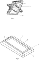
Fig. 1 shows a perspective view of a prior art roof window, -
Fig. 2 shows a perspective view of a window system according to the invention, where the window is in a closed position, -
Fig. 3 is a view corresponding to that ofFig. 2 , where the window system is equipped with the wind deflector, -
Fig. 4 is a detail view corresponding to that ofFig. 3 , where the window is equipped with the wind deflector, -
Fig. 5 is a detail view corresponding to that ofFig. 3 , where the window is equipped with second embodiment of the wind deflector, -
Fig. 6 shows a perspective view of a window system according to the invention, where the roof window is in an open schematic position, -
Fig. 7 shows a schematic drawing of the window system and the opening areas for the roof window opening and the area between window and deflector, -
Fig. 8 shows a perspective view of a third embodiment of a window system with a deflector according to the invention, where the deflector is shown placed at a single roof window, and -
Fig. 9 shows a perspective view of a third embodiment of a window system with a deflector according to the invention, where the deflector is shown placed at the middle of three roof windows arranged side by side. -
Fig. 1 illustrates a priorart roof window 1 comprising a frame structure. The roof window system represented infigure 1 also comprises anoperator 8 of a standard type, e.g. a chain operator to open and close the window, useful for moving the sash with respect to the stationary frame. The figure also shows a roof window system surrounded by a smoke deflector attached to the frame of the window. - A perspective view of a window system according to the invention is shown in
figure 2 , where theroof window 1 comprising a frame structure comprising a first and a second pair of mutually opposite frame members is shown. The first pair consists of one member in the form of a top member and another member in the form of a bottom member. The two members of the second pair constitute mutually opposite side members, each extending between the top and bottom members to form a substantially rectangular frame intended to be built-in in e.g. an inclined roof (not shown). Theroof window 1 infigure 2 in a similar manner also comprises a first and a second pair of sash members, a topsash member 2 and bottomsash member 4 and mutually opposite pair ofside sash members 3. The window system is depicted in a closed position, and is placed in a flashing 5 in an underlying roof structure (not shown). In the sash a window pane of any type, e.g. an insulating unit, may be encased. The inclination may be defined by the roof pitch, which for example could be in the range 5-15° with respect to a horizontal plane. -
Fig. 3 is a view corresponding to that ofFig. 2 , where the window system is equipped with thewind deflector 10 in accordance with the invention. Thewind deflector kit side elements 130 with a suitable shape so as to facilitate easy mounting, sturdyness in the mounted condition and effective wind deflection, such as, but not limited to, a rectangular, square or triangular shape. The wind deflector kit may also compriseside elements 130 integrated with thecorner elements 120, thus forming a unitary wind deflector structure in this manner. - The wind deflector kit may be integrated with the
side mounting flanges 135, thus forming a unitary wind deflector structure in this manner. - The wind deflector kit may include at least two additional
centre mounting flanges 110, placed at a distance from theside mounting flanges 130. - The wind deflector kit may alternatively comprise that the
side elements 130 are integrated both with thecorner elements 120 and theside mounting flanges 135 and that the said additionalcentre mounting flanges 110 also are integrated with thecorner elements 135 placed at distance opposite from theside mounting flanges 130 to form the unitary wind deflector structure in this manner. - Said wind
deflector kit elements - The unitary wind deflector structure (10, 10*, 10**) is at a distance (Ddwb) from the roof window bottom equal to the height (Dh) of the said deflector structure. Said distance (Ddwb) is preferably in the range of 20 to 50 cm, more preferred in the range of 25 to 45 cm and most preferred in the range from 30 to 40 cm. The unitary wind deflector structure (10, 10*, 10**) is at a distance (Ddws) from the window sides less than half the said height (Dh), preferably in the range of 10 to 50 cm, more preferred in the range of 10 to 40 cm and most preferred 10 to 30 cm.
-
Fig. 6 shows a perspective view of a window system according to the invention, where theroof window 1 is in an open schematic position, where it is possible to see the frame and sash structures respectively, with thetop members side members bottom member operator member 8, which is intended to open and close theroof window 1. Last, theflashing structure 5 can be seen. -
Fig. 7 illustrates a schematic drawing of the roof window and the opening areas (A1-A3) for the window opening and the area (D1-D3) between window and deflector. These values can indirectly be used to calculate the deflectors influence on the wind flow over the window opening. The aerodynamic area is calculated using the Cv factor, which determines the relation between the geometric area and the aerodynamic area of the window. The Cv factor expresses the effectiveness of the smoke ventilation. The aerodynamic area of a window is determined by EN 12101-5 (2005). Here the Cv factor is set to 0,7 as this is the physical contraction that occurs when air passes through openings. A combination of openings renders the resulting aerodynamic area where the total contraction is greatest, i.e the smallest effective area. That means that a plurality of openings in series will reduce the effective opening. The formula from EN 12101-5 takes this into account:
- A indicates the individual opening areas of the window, A1 is the frame opening area, A2 is the opening area between the frame and sash bottoms while A3 is the opening area of the two triangles at the frame and sash sides, see
figure 8 . - The opening area for the three sides can then be added so that the window has a total opening area. As an example, calculations for one size window were made to illustrate the influence at the aerodynamic area created by the window dimensions and the length of the operator member, here is used a standard chain operator. The graph in the below Table 1 shows the ratio of the distance from the deflector to the window and the influence of the aerodynamic area for the window.

- The deflector distance is divided into respectively; "Afstand foran" (distance in front) and "Afstand siderne" (distance on the sides), so that it is possible to see how the two different distances affect the aerodynamic area and thus choose the optimum location of the deflector. The distance varies from 0,1 to 0,6 m. From this illustration it becomes evident that the distance (Ddwb) between the unitary
wind deflector structure roof window bottom wind deflector structure -
Fig. 8 illustrates a third embodiment of a roof window system according to the invention comprising adeflector 10** placed at a flashing 5 at a distance (Ddwb) from the window bottom. This third embodiment is different due to the triangular shape of the winddeflector side elements 130. The shownwind deflector kit side elements 130, twocorner elements 120, twoside mounting flanges 135 and onefront element 100. The elements are to be assembled to a unitary wind deflector structure placed alongside the outside of the window frame and sash bottom and partially alongside the lower parts of the two window frame and sash sides. Also shown in thefigure 8 is that thewind deflector kit side elements 130 integrated, not only to thecorner elements 120 and theside mounting flanges 135, but also to the two additionalcentre mounting flanges 110, placed at distance and opposite from theside mounting flanges 130. By integration of the fourelements front element 100, thus forming the unitary wind deflector structure. Depending upon the length of thefront element 100 and how much it is intended to overlap the corner part of the single piece component, the overall length of the wind deflector structure can be adjusted or modified in accordance with the required installation situation, i.e. dependent on the size of the window and the flashing used. -
Fig. 9 shows a perspective view of a third embodiment of a window system with adeflector 10 according to the invention, where thedeflector 10 is shown placed at the middle of threeroof windows 1 arranged side by side. Theside elements 130 of thewind deflector kit 10 only extend minimally in and over the adjacent or neighboringroof windows 1. Thefront element 100 and the twocorner elements 120 of the kit can be seen to be assembled via common connection means 200 (not disclosed in detail herein). - The roof window comprises a frame structure including a plurality of frame members, a sash structure carrying a pane element and including a plurality of sash members, an operator including an operator member having a first and a second end and adapted to extend between the frame structure and the sash structure, the sash being pivotally connected to the frame so that a pivotal opening movement of the sash in relation to the frame moves the window between a closed position and a fully opened position where the smoke can exit through the opening.
- Furthermore the roof window may comprise a traditional chain actuator configured at least for performing the closure of the window. The window being configured with a chain actuator has the effect of providing closing assisting means, such that the window for example could be self closing and locking.
- The invention should not be regarded as being limited to the embodiments described in the above, but various modifications and combinations may be carried out. For example this disclosure may be employed in roof windows which are top hanged, bottom hanged or semi-top hanged.
Claims (9)
- A window system comprising a roof window (1) with top, side, and bottom members where the frame structure includes a plurality of frame members, top, side and bottom (20,30,40), a sash structure carrying a pane element and includes a plurality of sash members, top, side and bottom (2,3,4), an operator includes an operator member (8) having a first and a second end and adapted to extend between the frame structure and the sash structure, said frame structure being adapted to be installed in a roof structure, a flashing arrangement (5) surrounding the said window frame and sash structures, comprising a plurality of flashing members, and a wind deflecting kit (10) placed outside the said frame and sash structures and on the outside of the said flashing arrangement (5),
characterized in that the said wind deflector kit (10, 10*, 10**) includes a plurality of elements, comprising at least two side elements (130), two corner elements (120), two side mounting flanges (135) and one front element (100), which elements are to be assembled to a unitary wind deflector structure placed alongside the outside of the window frame and sash bottom and partially alongside the lower parts of the two window frame and sash sides. - A window system according to claim 1, wherein the wind deflector kit (10, 10*, 10**) has side elements with a rectangular, square or triangular shape.
- A window system according to claim 1 or 2, wherein the wind deflector kit (10, 10*, 10**) comprises that the side elements (130) are integrated both with the corner elements (120) and the side mounting flanges (135) to form the unitary wind deflector structure.
- A window system according to any one of the previous claims, wherein said wind deflector kit (10, 10*, 10**) includes at least two additional centre mounting flanges (110), placed at distance from the side mounting flanges (130).
- A window system according to claim 3 and 4, wherein the wind deflector kit (10, 10*, 10**) comprises that the side elements (130) are integrated both with the corner elements (120) and the side mounting flanges (135) and that the said additional centre mounting flanges (110) also are integrated with the corner elements (135) placed at distance opposite from the side mounting flanges (130) to form the unitary wind deflector structure.
- A window system according to any one of the previous claims, wherein the wind deflector kit elements (10, 100, 110, 120, 130) all have the same height, preferably in the range of 20 to 60 cm, more preferred in the range of 25 to 50 cm and most preferred in the range from 30 to 40 cm.
- A window system according to any one of the previous claims, wherein the unitary wind deflector structure (10, 10*, 10**) is placed at a distance (Ddwb) from the roof window bottom equal to the height (Dh) of the said deflector structure and at a distance (Ddws) from the window sides less than half the said height (Dh).
- A window system according to any one of the previous claims, wherein distance (Ddwb) between the unitary wind deflector structure (10, 10*, 10**) and the roof window bottom, preferably is in the range of 20 to 50 cm, more preferred in the range of 25 to 45 cm and most preferred in the range from 30 to 40 cm, and the distance (Ddws) between the sides of the unitary wind deflector structure (10, 10*, 10**) and the window sides, preferably is in the range of 10 to 50 cm, more preferred in the range of 10 to 40 cm and most preferred 10 to 30 cm.
- A window system according to any one of the previous claims, wherein the unitary wind deflector structure (10, 10*, 10**) is placed at a distance (Ddf) above the flashing arrangement (5) to create a clearance area between the said deflector structure and the flashing arrangement.
Priority Applications (1)
| Application Number | Priority Date | Filing Date | Title |
|---|---|---|---|
| PL17196220T PL3309317T3 (en) | 2016-10-12 | 2017-10-12 | Improved smoke ventilating roof window arrangement |
Applications Claiming Priority (1)
| Application Number | Priority Date | Filing Date | Title |
|---|---|---|---|
| DKPA201670803A DK179627B1 (en) | 2016-10-12 | 2016-10-12 | Smoke ventilating roof window arrangement |
Publications (2)
| Publication Number | Publication Date |
|---|---|
| EP3309317A1 true EP3309317A1 (en) | 2018-04-18 |
| EP3309317B1 EP3309317B1 (en) | 2019-10-09 |
Family
ID=60083820
Family Applications (1)
| Application Number | Title | Priority Date | Filing Date |
|---|---|---|---|
| EP17196220.2A Active EP3309317B1 (en) | 2016-10-12 | 2017-10-12 | Improved smoke ventilating roof window arrangement |
Country Status (3)
| Country | Link |
|---|---|
| EP (1) | EP3309317B1 (en) |
| DK (1) | DK179627B1 (en) |
| PL (1) | PL3309317T3 (en) |
Citations (5)
| Publication number | Priority date | Publication date | Assignee | Title |
|---|---|---|---|---|
| GB562869A (en) * | 1943-01-06 | 1944-07-19 | Ralph Gelder | Improved device for the ventilation of buildings |
| DE7405961U (en) * | 1974-02-21 | 1975-10-16 | Grescha Gesellschaft Grefe & Scharf | VENTILATION TOP FOR BUILDING ROOMS |
| FR2535443A1 (en) * | 1982-10-28 | 1984-05-04 | Souchier Fages | Ventilation and smoke evacuation device, especially for industrial sites or public buildings. |
| EP1870555A1 (en) * | 2006-06-21 | 2007-12-26 | VKR Holding A/S | Kit of deflector elements and window comprising such a kit |
| DE102010026004A1 (en) * | 2010-07-03 | 2012-01-05 | Eduard Hueck Gmbh & Co Kg | Ventilation device i.e. garret window, for use as natural smoke and heat extraction device at roof, has air guiding unit arranged outside passage opening and besides or at frame side, which is provided opposite to pivot bearing |
Family Cites Families (4)
| Publication number | Priority date | Publication date | Assignee | Title |
|---|---|---|---|---|
| FR2841921B1 (en) * | 2002-07-04 | 2005-01-14 | Hexadome Sa | EXHIBITION OF DESENFUMAGE COMPRISING RETRACTABLE WINDSHIELD SHUTTERS |
| FR2887572B1 (en) * | 2005-06-24 | 2007-09-14 | Ecodis Etude Coordination Dist | EXAMPLE OF SMOKE WITH WINDSCREEN |
| PL217336B1 (en) * | 2008-10-21 | 2014-07-31 | Fakro Pp Spółka Z Ograniczoną Odpowiedzialnością | Roof window, preferably the smoke extracting window, with swivel casement |
| US20120304567A1 (en) * | 2011-06-01 | 2012-12-06 | Hi-Tech Plastics, LLC | Roof vent |
-
2016
- 2016-10-12 DK DKPA201670803A patent/DK179627B1/en active IP Right Grant
-
2017
- 2017-10-12 EP EP17196220.2A patent/EP3309317B1/en active Active
- 2017-10-12 PL PL17196220T patent/PL3309317T3/en unknown
Patent Citations (5)
| Publication number | Priority date | Publication date | Assignee | Title |
|---|---|---|---|---|
| GB562869A (en) * | 1943-01-06 | 1944-07-19 | Ralph Gelder | Improved device for the ventilation of buildings |
| DE7405961U (en) * | 1974-02-21 | 1975-10-16 | Grescha Gesellschaft Grefe & Scharf | VENTILATION TOP FOR BUILDING ROOMS |
| FR2535443A1 (en) * | 1982-10-28 | 1984-05-04 | Souchier Fages | Ventilation and smoke evacuation device, especially for industrial sites or public buildings. |
| EP1870555A1 (en) * | 2006-06-21 | 2007-12-26 | VKR Holding A/S | Kit of deflector elements and window comprising such a kit |
| DE102010026004A1 (en) * | 2010-07-03 | 2012-01-05 | Eduard Hueck Gmbh & Co Kg | Ventilation device i.e. garret window, for use as natural smoke and heat extraction device at roof, has air guiding unit arranged outside passage opening and besides or at frame side, which is provided opposite to pivot bearing |
Also Published As
| Publication number | Publication date |
|---|---|
| DK179627B1 (en) | 2019-03-05 |
| DK201670803A1 (en) | 2018-04-23 |
| EP3309317B1 (en) | 2019-10-09 |
| PL3309317T3 (en) | 2020-03-31 |
Similar Documents
| Publication | Publication Date | Title |
|---|---|---|
| US20160146499A1 (en) | Gable Vent That Blocks Fire, Rain and Water | |
| DE102014114900B3 (en) | Cooling air system and spray water protection arrangement for a cooling air system of a housing and electrical or electronic device with a housing | |
| US8684803B2 (en) | Vent structure forcing a Z-pattern air flow | |
| DE102014115452B4 (en) | Closure arrangement on a ventilation opening in a ceiling of an elevator shaft | |
| EP2762797B1 (en) | Venting hood | |
| EP3309317B1 (en) | Improved smoke ventilating roof window arrangement | |
| DE202015106193U1 (en) | Air curtain system | |
| EP1436553B1 (en) | Sliding door device | |
| DE102021107478B4 (en) | Ventilation head for the ventilation of buildings | |
| EP1870555B1 (en) | Ventilation unit | |
| DE102007029554A1 (en) | Method of de-smoking and ventilating an underground station | |
| EP2634501B1 (en) | Ventilation device, in particular for buildings | |
| DE3324153A1 (en) | OBJECT GUARD | |
| DE202015106194U1 (en) | Air curtain system | |
| DE202012013340U1 (en) | Smoke extraction facility | |
| EP3009591B1 (en) | Ventilation grid | |
| EP3853425B1 (en) | Multi-storey building with secure access routes and escape routes in the event of fire | |
| WO2014040672A1 (en) | Air inlet system for a stationary internal combustion engine, in particular for a stationary gas turbine | |
| DE202016008451U1 (en) | Device for ventilating rooms in the area of a window | |
| DE102006043936A1 (en) | Wind turbine, has opening i.e. person doorway, provided in tower wall, and multiple air filters arranged at opening, where air filters have air passage surfaces that are larger than surface of opening | |
| DE102008039080A1 (en) | Housing with burglar proof door hinge | |
| DE102013107382A1 (en) | Hood unit for vehicle | |
| EP3936694B1 (en) | Double window | |
| EP2159341A2 (en) | Windshield of a fire gas vent | |
| DE102013111958A1 (en) | Device for covering chimneys or chimneys |
Legal Events
| Date | Code | Title | Description |
|---|---|---|---|
| PUAI | Public reference made under article 153(3) epc to a published international application that has entered the european phase |
Free format text: ORIGINAL CODE: 0009012 |
|
| STAA | Information on the status of an ep patent application or granted ep patent |
Free format text: STATUS: THE APPLICATION HAS BEEN PUBLISHED |
|
| AK | Designated contracting states |
Kind code of ref document: A1 Designated state(s): AL AT BE BG CH CY CZ DE DK EE ES FI FR GB GR HR HU IE IS IT LI LT LU LV MC MK MT NL NO PL PT RO RS SE SI SK SM TR |
|
| AX | Request for extension of the european patent |
Extension state: BA ME |
|
| STAA | Information on the status of an ep patent application or granted ep patent |
Free format text: STATUS: REQUEST FOR EXAMINATION WAS MADE |
|
| 17P | Request for examination filed |
Effective date: 20181018 |
|
| RBV | Designated contracting states (corrected) |
Designated state(s): AL AT BE BG CH CY CZ DE DK EE ES FI FR GB GR HR HU IE IS IT LI LT LU LV MC MK MT NL NO PL PT RO RS SE SI SK SM TR |
|
| GRAP | Despatch of communication of intention to grant a patent |
Free format text: ORIGINAL CODE: EPIDOSNIGR1 |
|
| STAA | Information on the status of an ep patent application or granted ep patent |
Free format text: STATUS: GRANT OF PATENT IS INTENDED |
|
| INTG | Intention to grant announced |
Effective date: 20181210 |
|
| GRAJ | Information related to disapproval of communication of intention to grant by the applicant or resumption of examination proceedings by the epo deleted |
Free format text: ORIGINAL CODE: EPIDOSDIGR1 |
|
| STAA | Information on the status of an ep patent application or granted ep patent |
Free format text: STATUS: REQUEST FOR EXAMINATION WAS MADE |
|
| GRAP | Despatch of communication of intention to grant a patent |
Free format text: ORIGINAL CODE: EPIDOSNIGR1 |
|
| STAA | Information on the status of an ep patent application or granted ep patent |
Free format text: STATUS: GRANT OF PATENT IS INTENDED |
|
| INTC | Intention to grant announced (deleted) | ||
| INTG | Intention to grant announced |
Effective date: 20190516 |
|
| GRAS | Grant fee paid |
Free format text: ORIGINAL CODE: EPIDOSNIGR3 |
|
| GRAA | (expected) grant |
Free format text: ORIGINAL CODE: 0009210 |
|
| STAA | Information on the status of an ep patent application or granted ep patent |
Free format text: STATUS: THE PATENT HAS BEEN GRANTED |
|
| AK | Designated contracting states |
Kind code of ref document: B1 Designated state(s): AL AT BE BG CH CY CZ DE DK EE ES FI FR GB GR HR HU IE IS IT LI LT LU LV MC MK MT NL NO PL PT RO RS SE SI SK SM TR |
|
| REG | Reference to a national code |
Ref country code: GB Ref legal event code: FG4D |
|
| REG | Reference to a national code |
Ref country code: CH Ref legal event code: EP |
|
| REG | Reference to a national code |
Ref country code: IE Ref legal event code: FG4D |
|
| REG | Reference to a national code |
Ref country code: DE Ref legal event code: R096 Ref document number: 602017007638 Country of ref document: DE |
|
| REG | Reference to a national code |
Ref country code: AT Ref legal event code: REF Ref document number: 1188972 Country of ref document: AT Kind code of ref document: T Effective date: 20191115 |
|
| REG | Reference to a national code |
Ref country code: NL Ref legal event code: FP |
|
| REG | Reference to a national code |
Ref country code: LT Ref legal event code: MG4D |
|
| PG25 | Lapsed in a contracting state [announced via postgrant information from national office to epo] |
Ref country code: FI Free format text: LAPSE BECAUSE OF FAILURE TO SUBMIT A TRANSLATION OF THE DESCRIPTION OR TO PAY THE FEE WITHIN THE PRESCRIBED TIME-LIMIT Effective date: 20191009 Ref country code: NO Free format text: LAPSE BECAUSE OF FAILURE TO SUBMIT A TRANSLATION OF THE DESCRIPTION OR TO PAY THE FEE WITHIN THE PRESCRIBED TIME-LIMIT Effective date: 20200109 Ref country code: GR Free format text: LAPSE BECAUSE OF FAILURE TO SUBMIT A TRANSLATION OF THE DESCRIPTION OR TO PAY THE FEE WITHIN THE PRESCRIBED TIME-LIMIT Effective date: 20200110 Ref country code: SE Free format text: LAPSE BECAUSE OF FAILURE TO SUBMIT A TRANSLATION OF THE DESCRIPTION OR TO PAY THE FEE WITHIN THE PRESCRIBED TIME-LIMIT Effective date: 20191009 Ref country code: BG Free format text: LAPSE BECAUSE OF FAILURE TO SUBMIT A TRANSLATION OF THE DESCRIPTION OR TO PAY THE FEE WITHIN THE PRESCRIBED TIME-LIMIT Effective date: 20200109 Ref country code: ES Free format text: LAPSE BECAUSE OF FAILURE TO SUBMIT A TRANSLATION OF THE DESCRIPTION OR TO PAY THE FEE WITHIN THE PRESCRIBED TIME-LIMIT Effective date: 20191009 Ref country code: LV Free format text: LAPSE BECAUSE OF FAILURE TO SUBMIT A TRANSLATION OF THE DESCRIPTION OR TO PAY THE FEE WITHIN THE PRESCRIBED TIME-LIMIT Effective date: 20191009 Ref country code: LT Free format text: LAPSE BECAUSE OF FAILURE TO SUBMIT A TRANSLATION OF THE DESCRIPTION OR TO PAY THE FEE WITHIN THE PRESCRIBED TIME-LIMIT Effective date: 20191009 Ref country code: PT Free format text: LAPSE BECAUSE OF FAILURE TO SUBMIT A TRANSLATION OF THE DESCRIPTION OR TO PAY THE FEE WITHIN THE PRESCRIBED TIME-LIMIT Effective date: 20200210 |
|
| PG25 | Lapsed in a contracting state [announced via postgrant information from national office to epo] |
Ref country code: IS Free format text: LAPSE BECAUSE OF FAILURE TO SUBMIT A TRANSLATION OF THE DESCRIPTION OR TO PAY THE FEE WITHIN THE PRESCRIBED TIME-LIMIT Effective date: 20200224 Ref country code: HR Free format text: LAPSE BECAUSE OF FAILURE TO SUBMIT A TRANSLATION OF THE DESCRIPTION OR TO PAY THE FEE WITHIN THE PRESCRIBED TIME-LIMIT Effective date: 20191009 Ref country code: RS Free format text: LAPSE BECAUSE OF FAILURE TO SUBMIT A TRANSLATION OF THE DESCRIPTION OR TO PAY THE FEE WITHIN THE PRESCRIBED TIME-LIMIT Effective date: 20191009 |
|
| PG25 | Lapsed in a contracting state [announced via postgrant information from national office to epo] |
Ref country code: AL Free format text: LAPSE BECAUSE OF FAILURE TO SUBMIT A TRANSLATION OF THE DESCRIPTION OR TO PAY THE FEE WITHIN THE PRESCRIBED TIME-LIMIT Effective date: 20191009 |
|
| REG | Reference to a national code |
Ref country code: DE Ref legal event code: R097 Ref document number: 602017007638 Country of ref document: DE |
|
| PG2D | Information on lapse in contracting state deleted |
Ref country code: IS |
|
| PG25 | Lapsed in a contracting state [announced via postgrant information from national office to epo] |
Ref country code: DK Free format text: LAPSE BECAUSE OF FAILURE TO SUBMIT A TRANSLATION OF THE DESCRIPTION OR TO PAY THE FEE WITHIN THE PRESCRIBED TIME-LIMIT Effective date: 20191009 Ref country code: EE Free format text: LAPSE BECAUSE OF FAILURE TO SUBMIT A TRANSLATION OF THE DESCRIPTION OR TO PAY THE FEE WITHIN THE PRESCRIBED TIME-LIMIT Effective date: 20191009 Ref country code: RO Free format text: LAPSE BECAUSE OF FAILURE TO SUBMIT A TRANSLATION OF THE DESCRIPTION OR TO PAY THE FEE WITHIN THE PRESCRIBED TIME-LIMIT Effective date: 20191009 Ref country code: CZ Free format text: LAPSE BECAUSE OF FAILURE TO SUBMIT A TRANSLATION OF THE DESCRIPTION OR TO PAY THE FEE WITHIN THE PRESCRIBED TIME-LIMIT Effective date: 20191009 Ref country code: LU Free format text: LAPSE BECAUSE OF NON-PAYMENT OF DUE FEES Effective date: 20191012 Ref country code: MC Free format text: LAPSE BECAUSE OF FAILURE TO SUBMIT A TRANSLATION OF THE DESCRIPTION OR TO PAY THE FEE WITHIN THE PRESCRIBED TIME-LIMIT Effective date: 20191009 Ref country code: IS Free format text: LAPSE BECAUSE OF FAILURE TO SUBMIT A TRANSLATION OF THE DESCRIPTION OR TO PAY THE FEE WITHIN THE PRESCRIBED TIME-LIMIT Effective date: 20200209 |
|
| PLBE | No opposition filed within time limit |
Free format text: ORIGINAL CODE: 0009261 |
|
| STAA | Information on the status of an ep patent application or granted ep patent |
Free format text: STATUS: NO OPPOSITION FILED WITHIN TIME LIMIT |
|
| PG25 | Lapsed in a contracting state [announced via postgrant information from national office to epo] |
Ref country code: SM Free format text: LAPSE BECAUSE OF FAILURE TO SUBMIT A TRANSLATION OF THE DESCRIPTION OR TO PAY THE FEE WITHIN THE PRESCRIBED TIME-LIMIT Effective date: 20191009 Ref country code: SK Free format text: LAPSE BECAUSE OF FAILURE TO SUBMIT A TRANSLATION OF THE DESCRIPTION OR TO PAY THE FEE WITHIN THE PRESCRIBED TIME-LIMIT Effective date: 20191009 |
|
| 26N | No opposition filed |
Effective date: 20200710 |
|
| PG25 | Lapsed in a contracting state [announced via postgrant information from national office to epo] |
Ref country code: IE Free format text: LAPSE BECAUSE OF NON-PAYMENT OF DUE FEES Effective date: 20191012 |
|
| PG25 | Lapsed in a contracting state [announced via postgrant information from national office to epo] |
Ref country code: SI Free format text: LAPSE BECAUSE OF FAILURE TO SUBMIT A TRANSLATION OF THE DESCRIPTION OR TO PAY THE FEE WITHIN THE PRESCRIBED TIME-LIMIT Effective date: 20191009 |
|
| PG25 | Lapsed in a contracting state [announced via postgrant information from national office to epo] |
Ref country code: CY Free format text: LAPSE BECAUSE OF FAILURE TO SUBMIT A TRANSLATION OF THE DESCRIPTION OR TO PAY THE FEE WITHIN THE PRESCRIBED TIME-LIMIT Effective date: 20191009 |
|
| PG25 | Lapsed in a contracting state [announced via postgrant information from national office to epo] |
Ref country code: HU Free format text: LAPSE BECAUSE OF FAILURE TO SUBMIT A TRANSLATION OF THE DESCRIPTION OR TO PAY THE FEE WITHIN THE PRESCRIBED TIME-LIMIT; INVALID AB INITIO Effective date: 20171012 Ref country code: MT Free format text: LAPSE BECAUSE OF FAILURE TO SUBMIT A TRANSLATION OF THE DESCRIPTION OR TO PAY THE FEE WITHIN THE PRESCRIBED TIME-LIMIT Effective date: 20191009 |
|
| PG25 | Lapsed in a contracting state [announced via postgrant information from national office to epo] |
Ref country code: TR Free format text: LAPSE BECAUSE OF FAILURE TO SUBMIT A TRANSLATION OF THE DESCRIPTION OR TO PAY THE FEE WITHIN THE PRESCRIBED TIME-LIMIT Effective date: 20191009 |
|
| PG25 | Lapsed in a contracting state [announced via postgrant information from national office to epo] |
Ref country code: MK Free format text: LAPSE BECAUSE OF FAILURE TO SUBMIT A TRANSLATION OF THE DESCRIPTION OR TO PAY THE FEE WITHIN THE PRESCRIBED TIME-LIMIT Effective date: 20191009 |
|
| REG | Reference to a national code |
Ref country code: AT Ref legal event code: UEP Ref document number: 1188972 Country of ref document: AT Kind code of ref document: T Effective date: 20191009 |
|
| PGFP | Annual fee paid to national office [announced via postgrant information from national office to epo] |
Ref country code: PL Payment date: 20250912 Year of fee payment: 9 Ref country code: NL Payment date: 20250912 Year of fee payment: 9 Ref country code: IT Payment date: 20250922 Year of fee payment: 9 |
|
| PGFP | Annual fee paid to national office [announced via postgrant information from national office to epo] |
Ref country code: BE Payment date: 20250917 Year of fee payment: 9 Ref country code: GB Payment date: 20250904 Year of fee payment: 9 |
|
| PGFP | Annual fee paid to national office [announced via postgrant information from national office to epo] |
Ref country code: FR Payment date: 20250922 Year of fee payment: 9 |
|
| REG | Reference to a national code |
Ref country code: CH Ref legal event code: U11 Free format text: ST27 STATUS EVENT CODE: U-0-0-U10-U11 (AS PROVIDED BY THE NATIONAL OFFICE) Effective date: 20251101 |
|
| PGFP | Annual fee paid to national office [announced via postgrant information from national office to epo] |
Ref country code: DE Payment date: 20250902 Year of fee payment: 9 |
|
| PGFP | Annual fee paid to national office [announced via postgrant information from national office to epo] |
Ref country code: AT Payment date: 20250925 Year of fee payment: 9 |
|
| PGFP | Annual fee paid to national office [announced via postgrant information from national office to epo] |
Ref country code: CH Payment date: 20251101 Year of fee payment: 9 |