EP3309301B1 - Öffnungs- und schliessvorrichtung - Google Patents
Öffnungs- und schliessvorrichtung Download PDFInfo
- Publication number
- EP3309301B1 EP3309301B1 EP15894270.6A EP15894270A EP3309301B1 EP 3309301 B1 EP3309301 B1 EP 3309301B1 EP 15894270 A EP15894270 A EP 15894270A EP 3309301 B1 EP3309301 B1 EP 3309301B1
- Authority
- EP
- European Patent Office
- Prior art keywords
- gate
- float
- unit
- closing device
- opening
- Prior art date
- Legal status (The legal status is an assumption and is not a legal conclusion. Google has not performed a legal analysis and makes no representation as to the accuracy of the status listed.)
- Active
Links
Images






Classifications
-
- E—FIXED CONSTRUCTIONS
- E02—HYDRAULIC ENGINEERING; FOUNDATIONS; SOIL SHIFTING
- E02B—HYDRAULIC ENGINEERING
- E02B7/00—Barrages or weirs; Layout, construction, methods of, or devices for, making same
- E02B7/20—Movable barrages; Lock or dry-dock gates
- E02B7/205—Barrages controlled by the variations of the water level; automatically functioning barrages
-
- E—FIXED CONSTRUCTIONS
- E02—HYDRAULIC ENGINEERING; FOUNDATIONS; SOIL SHIFTING
- E02B—HYDRAULIC ENGINEERING
- E02B5/00—Artificial water canals, e.g. irrigation canals
- E02B5/08—Details, e.g. gates, screens
- E02B5/082—Closures
-
- E—FIXED CONSTRUCTIONS
- E02—HYDRAULIC ENGINEERING; FOUNDATIONS; SOIL SHIFTING
- E02B—HYDRAULIC ENGINEERING
- E02B7/00—Barrages or weirs; Layout, construction, methods of, or devices for, making same
- E02B7/20—Movable barrages; Lock or dry-dock gates
- E02B7/40—Swinging or turning gates
-
- E—FIXED CONSTRUCTIONS
- E02—HYDRAULIC ENGINEERING; FOUNDATIONS; SOIL SHIFTING
- E02B—HYDRAULIC ENGINEERING
- E02B7/00—Barrages or weirs; Layout, construction, methods of, or devices for, making same
- E02B7/20—Movable barrages; Lock or dry-dock gates
- E02B7/40—Swinging or turning gates
- E02B7/42—Gates of segmental or sector-like shape with horizontal axis
-
- E—FIXED CONSTRUCTIONS
- E02—HYDRAULIC ENGINEERING; FOUNDATIONS; SOIL SHIFTING
- E02B—HYDRAULIC ENGINEERING
- E02B7/00—Barrages or weirs; Layout, construction, methods of, or devices for, making same
- E02B7/20—Movable barrages; Lock or dry-dock gates
- E02B7/40—Swinging or turning gates
- E02B7/44—Hinged-leaf gates
-
- E—FIXED CONSTRUCTIONS
- E03—WATER SUPPLY; SEWERAGE
- E03F—SEWERS; CESSPOOLS
- E03F7/00—Other installations or implements for operating sewer systems, e.g. for preventing or indicating stoppage; Emptying cesspools
- E03F7/02—Shut-off devices
-
- E—FIXED CONSTRUCTIONS
- E03—WATER SUPPLY; SEWERAGE
- E03F—SEWERS; CESSPOOLS
- E03F7/00—Other installations or implements for operating sewer systems, e.g. for preventing or indicating stoppage; Emptying cesspools
- E03F7/02—Shut-off devices
- E03F7/04—Valves for preventing return flow
-
- E—FIXED CONSTRUCTIONS
- E03—WATER SUPPLY; SEWERAGE
- E03F—SEWERS; CESSPOOLS
- E03F9/00—Arrangements or fixed installations methods or devices for cleaning or clearing sewer pipes, e.g. by flushing
- E03F9/007—Devices providing a flushing surge
-
- F—MECHANICAL ENGINEERING; LIGHTING; HEATING; WEAPONS; BLASTING
- F16—ENGINEERING ELEMENTS AND UNITS; GENERAL MEASURES FOR PRODUCING AND MAINTAINING EFFECTIVE FUNCTIONING OF MACHINES OR INSTALLATIONS; THERMAL INSULATION IN GENERAL
- F16K—VALVES; TAPS; COCKS; ACTUATING-FLOATS; DEVICES FOR VENTING OR AERATING
- F16K31/00—Actuating devices; Operating means; Releasing devices
- F16K31/12—Actuating devices; Operating means; Releasing devices actuated by fluid
- F16K31/18—Actuating devices; Operating means; Releasing devices actuated by fluid actuated by a float
- F16K31/20—Actuating devices; Operating means; Releasing devices actuated by fluid actuated by a float actuating a lift valve
- F16K31/28—Actuating devices; Operating means; Releasing devices actuated by fluid actuated by a float actuating a lift valve with two ore more floats actuating one valve
-
- F—MECHANICAL ENGINEERING; LIGHTING; HEATING; WEAPONS; BLASTING
- F16—ENGINEERING ELEMENTS AND UNITS; GENERAL MEASURES FOR PRODUCING AND MAINTAINING EFFECTIVE FUNCTIONING OF MACHINES OR INSTALLATIONS; THERMAL INSULATION IN GENERAL
- F16K—VALVES; TAPS; COCKS; ACTUATING-FLOATS; DEVICES FOR VENTING OR AERATING
- F16K33/00—Floats for actuation of valves or other apparatus
-
- Y—GENERAL TAGGING OF NEW TECHNOLOGICAL DEVELOPMENTS; GENERAL TAGGING OF CROSS-SECTIONAL TECHNOLOGIES SPANNING OVER SEVERAL SECTIONS OF THE IPC; TECHNICAL SUBJECTS COVERED BY FORMER USPC CROSS-REFERENCE ART COLLECTIONS [XRACs] AND DIGESTS
- Y10—TECHNICAL SUBJECTS COVERED BY FORMER USPC
- Y10T—TECHNICAL SUBJECTS COVERED BY FORMER US CLASSIFICATION
- Y10T137/00—Fluid handling
- Y10T137/7287—Liquid level responsive or maintaining systems
- Y10T137/7358—By float controlled valve
- Y10T137/7404—Plural floats
Definitions
- an opening/closing device used in a flow passage such as a sewer (refer to Patent Document 1, for example).
- the opening/closing device is used to clean a section where garbage tends to be accumulated such as a slack portion or an inverted siphon structure of a flow passage.
- Such an opening/closing device usually dams the flow passage while a valve element (or a gate) is closed. Therefore, flowing sewage is gradually accumulated, and when a water level of the flow passage becomes equal to or more than a predetermined water level, the valve element falls down, and enters an open state, the water flows at once toward downstream of the flow passage, and the garbage can be flushed away even in the section that tends to accumulate the garbage. In other words, the flow passage can be cleaned.
- an opening/closing device includes: a gate that receives a flow of fluid, and is able to fall down toward a downstream direction of the flow; a fall prevention unit that supports the gate, thereby preventing the gate from falling down; a support release unit that releases the support for the gate by the fall prevention unit; a first float that is arranged on an upstream side of the gate, is arranged on one of the left side and the right side of the gate viewed from upstream, and is less in the specific gravity than the fluid; a floating prevention unit that prevents the first float from floating; a second float that is arranged on the upstream side of the gate, is arranged on the other one of the left side and the right side of the gate viewed from upstream, and is less in the specific gravity than the fluid; and a floating prevention release unit that releases the prevention of the first float from the floating by the floating prevention unit as the second float floats, wherein the support release unit is activated as the first float floats.
- a gate receives a flow of fluid, and is able to fall down toward a downstream direction of the flow.
- a fall prevention unit supports the gate, thereby preventing the gate from falling down.
- a support release unit releases the support for the gate by the fall prevention unit.
- a first float is arranged on an upstream side of the gate, is arranged on one of the left side and the right side of the gate viewed from upstream, and is less in the specific gravity than the fluid.
- a floating prevention unit prevents the first float from floating.
- a second float is arranged on the upstream side of the gate, is arranged on the other one of the left side and the right side of the gate viewed from upstream, and is less in the specific gravity than the fluid.
- a floating prevention release unit releases the prevention of the first float from the floating by the floating prevention unit as the second float floats.
- the support release unit is activated as the first float floats.
- the fall prevention unit may support a surface on a downstream side of the gate.
- the floating prevention unit may include a rotatable portion that is able to rotate about the fixing portion; moreover, the abutting portion may rotate by an angle by which the rotatable portion rotates; and the floating prevention release unit may include a drive unit that moves the rotatable portion as the second float floats.
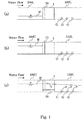
- the sewer 100U is located on an upstream side, and the sewer 100L is located on a downstream side. It is herein assumed that a flow passage where garbage G tends to be accumulated in the sewer 100L if an opening/closing device is absent.
- the opening/closing device 1 is arranged between the sewer 100U and the sewer 100L through a manhole, which is not shown.
- the water level of a sewage W flowing in the sewer 100U is usually low (refer to FIG. 1(a) ).
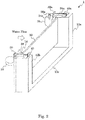
- the gate 10 is in an upright state, and receives the sewage W (a type of fluid) flowing through the sewer 100U.
- the sewage W is then dammed by the gate 10, and the sewage W does not flow to the sewer 100L on the downstream side.
- the garbage G is accumulated by sewage flowing into the sewer 100L.
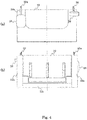
- FIG. 5 shows side views of the opening/closing device 1, and shows a left side view ( FIG. 5(a) ) and a right side view ( FIG. 5(b) ) viewed from the upstream side.
- FIG. 6 shows an enlarged front view ( FIG. 6(a) ) (viewed from the upstream side) of a neighborhood of a floating prevention unit 44 of the opening/closing device 1 and an enlarged front view of a neighborhood of the first float 18 ( FIG. 6(b) ).
- FIG. 7 is a plan view transparently showing neighborhoods of fall prevention units 20a and 20b while the gate 10 is in the upright state.
- the first support release unit 22a and the second support release unit 22b are symmetrical in a left/right direction viewed from the upstream side (and also viewed from the downstream side).
- the floating prevention release unit (drive unit) 42 releases the prevention of the floating of the first float 18 by the floating prevention unit 44 in this way as the second float 16 floats.
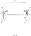
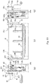
- the common rotation shaft 28 is arranged inside the hollow gate rotation shaft 26, and extends in the same direction as the gate rotation shaft 26 referring to FIG. 13(c) .
- the first support release unit 22a is in a shape bent approximately by the right angle, is coupled to the descending portion 24a at a horizontal portion thereof, is coupled to the fall prevention unit 20a at a portion extending in the up/down direction, and can rotate about the portion bent by the right angle.
- the rotation unit 29b and the descending portion 24b constitute a second release action unit.
- the rotation unit 29b rotates to cause the descending portion 24b to descend, thereby pulling the second support release unit 22b, resulting in the activation of the second support release unit 22b.
- the second release action unit (rotation unit 29b and descending portion 24b) and the first release action unit (rotation unit 29a and descending portion 24a) are symmetrical in the left/right direction viewed from the upstream side (and also viewed from the downstream side).
- the water level of the sewage W increases due to a rainfall or the like.
- the first float 18 is submerged in the sewage W, the specific gravity of the first float 18 is less than the specific gravity of the sewage W, the first float 18 would thus float, and the top end of the first float 18 would exceed the water level of the sewage W. However, the first float 18 does not float.
- the water level of the sewage W increases further.
- the second float 16 When the second float 16 is partially submerged in the sewage W, and floats quickly, the second float support beam 41 rotates about the fulcrum 41a, and the connection point 41b ascends. Then, the floating prevention release unit (drive unit) 42 ascends, and pushes and moves the rotatable portion 44c upward, and the rotatable portion 44c rotates about the fixing portion 44a. Then, the abutting portion 44b moves from above the ascending member 38 (refer to FIG. 11 ), and there exists nothing that prevents the portion of the ascending member 38 immediately below the abutting portion 44b from ascending. There thus exists nothing that prevents the ascending portion 380a of the suspension member 38a from ascending, and there also exists nothing that prevents the first float 18 from floating.
- the first support release unit 22a and the second support release unit 22b are activated.
- FIG. 14 is a right side view of the opening/closing device 1 after the sewage W has flown toward the downstream side.
- the first float 18 descends while floating on the water surface of the sewage W.
- the ascending member 38 also returns to the horizontal position.
- the second float 16 descends, the connection point 41b also descends, and the floating prevention unit 44 returns to the original position for pressing the ascending member 38 (refer to FIG. 6(a) ).
- the floating prevention unit 44 even when the first float 18 is submerged in the sewage W, the floating prevention unit 44 still presses the ascending member 38 until the second float 16 floats (refer to FIG. 6(a) ), and the first float 18 thus cannot float.
- the rotation unit 29a rotates, the common rotation shaft 28 rotates, the rotation unit 29b rotates (clockwise in FIG. 5(b) ), the descending portion 24b descends, thereby pulling the second support release unit 22b (refer to FIG. 13 ), the fall prevention unit 20b is pulled, and the support for the gate 10 is released.
- the transmission of the action through the pulling is useful in principle for carrying out the release of the support at the same time for the gate 10 by the fall prevention units 20a and 20b.
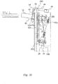
- FIG. 18 shows side views of the opening/closing device 1 when the gate 10 is in the upright state, and shows a left side view ( FIG. 18(a) ) and a right side view ( FIG. 15(b) ) viewed from the upstream side.
Landscapes
- Engineering & Computer Science (AREA)
- General Engineering & Computer Science (AREA)
- Structural Engineering (AREA)
- Mechanical Engineering (AREA)
- Civil Engineering (AREA)
- Water Supply & Treatment (AREA)
- Public Health (AREA)
- Hydrology & Water Resources (AREA)
- Life Sciences & Earth Sciences (AREA)
- Health & Medical Sciences (AREA)
- Barrages (AREA)
- Sewage (AREA)
- Devices For Checking Fares Or Tickets At Control Points (AREA)
Claims (7)
- Eine Öffnungs-/Schließvorrichtung (1) aufweisend:ein Tor (10), das einen Fluss eines Fluids empfängt, und in der Lage ist, nach unten zu fallen, in Richtung einer stromabwärtigen Richtung des Flusses;eine Fallverhinderungseinheit (20a, 20b) die das Tor (10) stützt und dabei verhindert, dass das Tor (10) nach unten fällt;eine Stützlöseeinheit (22a, 22b), die die Abstützung des Tors (10) durch die Fallverhinderungseinheit (20a, 20b) löst;ein erster Schwimmkörper (18), der auf einer stromaufwärtigen Seite des Tors (10) angeordnet ist und der, von stromaufwärtig gesehen, an entweder der linken Seite oder der rechten Seite des Tors (10) angeordnet ist und der eine geringere spezifische Gewichtskraft als das Fluid aufweist;eine Schwimmverhinderungseinheit (44), die verhindert, dass der erste Schwimmkörper (18) schwimmt;einen zweiten Schwimmkörper (16), der an der stromaufwärtigen Seite des Tors (10) angeordnet ist, und der eine geringere spezifische Gewichtskraft als das Fluid aufweist; undeine Schwimmverhinderungslöseeinheit (42), die die Verhinderung des ersten Schwimmkörpers (18) durch die Schwimmverhinderungseinheit (44) zu schwimmen löst, wenn der zweite Schwimmkörper (16) schwimmt;wobei die Stützlöseeinheit (22a, 22b) aktiviert wird, wenn der erste Schwimmkörper (18) schwimmt, dadurch gekennzeichnet, dassder zweite Schwimmkörper (16), von stromaufwärtig gesehen, an der anderen Seite der linken oder rechten Seite des Tors (10) angeordnet ist.
- Die Öffnungs-/Schließvorrichtung gemäß Anspruch 1, wobei die Fallverhinderungseinheit (20a, 20b) an einer stromabwärtigen Seite des Tors (10) eine Fläche abstützt ist.
- Die Öffnungs-/Schließvorrichtung gemäß Anspruch 1, wobei die Stützlöseeinheit (22a, 22b) die Fallverhinderungseinheit (20a, 20b) zu einer Außenseite des Flusses zieht und dabei die Abstützung des Tores (10) löst.
- Die Öffnungs-/Schließvorrichtung gemäß Anspruch 1, aufweisend:ein Aufhängungsglied (38a), das den ersten Schwimmkörper (18) hält und das einen Bereich (380a) aufweist, der sich nach oben bewegt, wenn der erste Schwimmkörper (18) schwimmt; undein Aufstiegsglied (38), das oberhalb des zweiten Schwimmkörpers (16) angeordnet ist, und einen Bereich (380) aufweist, der sich nach oben bewegt, wenn sich der sich nach oben bewegende Bereich (380a) des Aufhängungsglieds (38a) nach oben bewegt, wobei die Schwimmverhinderungseinheit (44) aufweist:einen Anstoßbereich (44b) der oberhalb des Aufstiegsglieds (38) angeordnet ist, und der gegen das Aufstiegsglied (38) ansteht, wenn der sich nach oben bewegende Bereich des Aufstiegsglied (38) sich nach oben bewegt; undeinen Befestigungsbereich (44a) der den Anstoßbereich (44b) an einem Bereich, der bezüglich des Flusses stationär ist, drehbar befestigt.
- Die Öffnungs-/Schließvorrichtung gemäß Anspruch 4, wobei das Aufstiegsglied (38) und das Aufhängungsglied (38a) miteinander über eine Drehwelle (28) gekoppelt sind, die sich in die gleiche Richtung erstreckt, wie das Drehzentrum des Tors (10).
- Die Öffnungs-/Schließvorrichtung gemäß Anspruch 4 oder 5, wobei:die Schwimmverhinderungseinheit (44) einen drehbaren Teil (44c) aufweist, der in der Lage ist, um den Befestigungsbereich (44a) herum zu drehen;weiterhin rotiert der Anstoßbereich (44b) um einen Winkel, um den der drehbare Teil (44c) rotiert; unddie Schwimmverhinderungslöseeinheit (42) weist eine Antriebseinheit auf, die den drehbaren Teil (44c) bewegt, wenn der zweite Schwimmkörper (16) schwimmt.
- Die Öffnungs-/Schließvorrichtung gemäß Anspruch 4 oder 5, aufweisend einen sich nach unten bewegenden Bereich (24a, 24b) der mit dem Aufhängungsglied (38a) gekoppelt ist, und der sich nach unten bewegt, wenn der sich nach oben bewegende Bereich (380a) des Aufhängungsglieds (38a) sich nach oben bewegt, wobei:die Stützlöseeinheit (22a, 22b) die Fallverhinderungseinheit (20a, 20b) zu einer Außenseite des Flusses zieht und dabei die Abstützung des Tors (10) löst; undweiterhin die Stützlöseeinheit (22a, 22b) mit dem sich nach unten bewegenden Bereich (24a, 24b) gekoppelt ist, und die Fallverhinderungseinheit (20a, 20b) zu einer Außenseite des Flusses zieht, in Antwort auf das sich nach unten Bewegen des sich nach unten bewegenden Bereichs (24a, 24b).
Applications Claiming Priority (2)
| Application Number | Priority Date | Filing Date | Title |
|---|---|---|---|
| JP2015114450A JP6277156B2 (ja) | 2015-06-05 | 2015-06-05 | 開閉装置 |
| PCT/JP2015/067647 WO2016194237A1 (ja) | 2015-06-05 | 2015-06-18 | 開閉装置 |
Publications (3)
| Publication Number | Publication Date |
|---|---|
| EP3309301A1 EP3309301A1 (de) | 2018-04-18 |
| EP3309301A4 EP3309301A4 (de) | 2019-04-17 |
| EP3309301B1 true EP3309301B1 (de) | 2020-11-25 |
Family
ID=57440305
Family Applications (1)
| Application Number | Title | Priority Date | Filing Date |
|---|---|---|---|
| EP15894270.6A Active EP3309301B1 (de) | 2015-06-05 | 2015-06-18 | Öffnungs- und schliessvorrichtung |
Country Status (10)
| Country | Link |
|---|---|
| US (1) | US10415201B2 (de) |
| EP (1) | EP3309301B1 (de) |
| JP (1) | JP6277156B2 (de) |
| KR (1) | KR102294110B1 (de) |
| AU (1) | AU2015397438B2 (de) |
| CA (1) | CA2987554C (de) |
| MY (1) | MY190918A (de) |
| PH (1) | PH12017502217B1 (de) |
| SG (1) | SG11201709984WA (de) |
| WO (1) | WO2016194237A1 (de) |
Families Citing this family (4)
| Publication number | Priority date | Publication date | Assignee | Title |
|---|---|---|---|---|
| CN107893408A (zh) * | 2017-12-07 | 2018-04-10 | 刘曼华 | 一种水面漂浮垃圾的垃圾收集装置 |
| CN109629659B (zh) * | 2018-10-31 | 2021-05-07 | 河南中拓石油工程技术股份有限公司 | 一种市政排水管道清淤装置及清淤工艺 |
| CN109958184B (zh) * | 2019-04-17 | 2020-09-18 | 同济大学 | 排水管道冲刷拦截装置 |
| CN110984082B (zh) * | 2019-12-27 | 2024-05-03 | 贵州省水利水电勘测设计研究院 | 一种渠道平面闸门双向止水结构 |
Family Cites Families (9)
| Publication number | Priority date | Publication date | Assignee | Title |
|---|---|---|---|---|
| JPS5166309A (en) | 1974-12-06 | 1976-06-08 | Shikoku Chem | Jinzosekibanno seizoho |
| FR2833978B1 (fr) * | 2001-12-20 | 2005-04-15 | Andre Pierre Simon | Dispositif de chasse automatique a clapet |
| NL1021680C2 (nl) * | 2002-10-17 | 2004-05-11 | Tbs Soest B V | Vlotterklep, vlotterstuw en werkwijze voor het gebruik daarvan. |
| DE10320308B3 (de) * | 2003-05-06 | 2004-06-03 | Giehl, Klaus-Ulrich, Dipl.-Ing. (FH) | Schwallspülvorrichtung zur Reinigung von Abwasserkanälen |
| JP2004360280A (ja) * | 2003-06-04 | 2004-12-24 | Kubota Corp | フラッシュゲート |
| JP2008106461A (ja) * | 2006-10-24 | 2008-05-08 | Kubota Corp | フラッシュゲート |
| JP5166309B2 (ja) | 2009-02-04 | 2013-03-21 | 日本工営株式会社 | 開閉装置 |
| JP5166311B2 (ja) * | 2009-02-04 | 2013-03-21 | 日本工営株式会社 | 開閉装置 |
| JP5166310B2 (ja) | 2009-02-04 | 2013-03-21 | 日本工営株式会社 | 開閉装置 |
-
2015
- 2015-06-05 JP JP2015114450A patent/JP6277156B2/ja active Active
- 2015-06-18 KR KR1020177034991A patent/KR102294110B1/ko active Active
- 2015-06-18 US US15/572,623 patent/US10415201B2/en active Active
- 2015-06-18 EP EP15894270.6A patent/EP3309301B1/de active Active
- 2015-06-18 MY MYPI2017704585A patent/MY190918A/en unknown
- 2015-06-18 AU AU2015397438A patent/AU2015397438B2/en active Active
- 2015-06-18 SG SG11201709984WA patent/SG11201709984WA/en unknown
- 2015-06-18 WO PCT/JP2015/067647 patent/WO2016194237A1/ja not_active Ceased
- 2015-06-18 CA CA2987554A patent/CA2987554C/en active Active
-
2017
- 2017-12-05 PH PH12017502217A patent/PH12017502217B1/en unknown
Non-Patent Citations (1)
| Title |
|---|
| None * |
Also Published As
| Publication number | Publication date |
|---|---|
| JP2017002483A (ja) | 2017-01-05 |
| CA2987554C (en) | 2021-04-20 |
| AU2015397438A1 (en) | 2017-12-14 |
| AU2015397438B2 (en) | 2020-09-10 |
| MY190918A (en) | 2022-05-19 |
| US20180135266A1 (en) | 2018-05-17 |
| SG11201709984WA (en) | 2017-12-28 |
| PH12017502217A1 (en) | 2018-06-11 |
| EP3309301A1 (de) | 2018-04-18 |
| PH12017502217B1 (en) | 2023-10-11 |
| KR20180015649A (ko) | 2018-02-13 |
| JP6277156B2 (ja) | 2018-02-07 |
| EP3309301A4 (de) | 2019-04-17 |
| US10415201B2 (en) | 2019-09-17 |
| CA2987554A1 (en) | 2016-12-08 |
| KR102294110B1 (ko) | 2021-08-26 |
| WO2016194237A1 (ja) | 2016-12-08 |
Similar Documents
| Publication | Publication Date | Title |
|---|---|---|
| CA2751408C (en) | Opening/closing device | |
| US8695628B2 (en) | Opening/closing device | |
| EP3309301B1 (de) | Öffnungs- und schliessvorrichtung | |
| JP5581538B2 (ja) | フロート式ドレントラップ | |
| JP3136061U (ja) | 下水管の逆流防止用の逆止弁装置 | |
| JP5166310B2 (ja) | 開閉装置 | |
| JP2009299308A (ja) | 逆流防止構造及び排水施設 | |
| JP5085961B2 (ja) | サイフォン排水システム | |
| JP7631162B2 (ja) | 逆流抑止継手 | |
| CN102537649A (zh) | 一种无视压差自动放水器 |
Legal Events
| Date | Code | Title | Description |
|---|---|---|---|
| STAA | Information on the status of an ep patent application or granted ep patent |
Free format text: STATUS: THE INTERNATIONAL PUBLICATION HAS BEEN MADE |
|
| PUAI | Public reference made under article 153(3) epc to a published international application that has entered the european phase |
Free format text: ORIGINAL CODE: 0009012 |
|
| STAA | Information on the status of an ep patent application or granted ep patent |
Free format text: STATUS: REQUEST FOR EXAMINATION WAS MADE |
|
| 17P | Request for examination filed |
Effective date: 20171130 |
|
| AK | Designated contracting states |
Kind code of ref document: A1 Designated state(s): AL AT BE BG CH CY CZ DE DK EE ES FI FR GB GR HR HU IE IS IT LI LT LU LV MC MK MT NL NO PL PT RO RS SE SI SK SM TR |
|
| AX | Request for extension of the european patent |
Extension state: BA ME |
|
| DAV | Request for validation of the european patent (deleted) | ||
| DAX | Request for extension of the european patent (deleted) | ||
| A4 | Supplementary search report drawn up and despatched |
Effective date: 20190318 |
|
| RIC1 | Information provided on ipc code assigned before grant |
Ipc: E03F 7/02 20060101ALI20190312BHEP Ipc: E02B 7/40 20060101AFI20190312BHEP Ipc: E03F 9/00 20060101ALI20190312BHEP |
|
| GRAP | Despatch of communication of intention to grant a patent |
Free format text: ORIGINAL CODE: EPIDOSNIGR1 |
|
| STAA | Information on the status of an ep patent application or granted ep patent |
Free format text: STATUS: GRANT OF PATENT IS INTENDED |
|
| INTG | Intention to grant announced |
Effective date: 20200608 |
|
| GRAS | Grant fee paid |
Free format text: ORIGINAL CODE: EPIDOSNIGR3 |
|
| GRAA | (expected) grant |
Free format text: ORIGINAL CODE: 0009210 |
|
| STAA | Information on the status of an ep patent application or granted ep patent |
Free format text: STATUS: THE PATENT HAS BEEN GRANTED |
|
| AK | Designated contracting states |
Kind code of ref document: B1 Designated state(s): AL AT BE BG CH CY CZ DE DK EE ES FI FR GB GR HR HU IE IS IT LI LT LU LV MC MK MT NL NO PL PT RO RS SE SI SK SM TR |
|
| REG | Reference to a national code |
Ref country code: GB Ref legal event code: FG4D |
|
| REG | Reference to a national code |
Ref country code: CH Ref legal event code: EP |
|
| REG | Reference to a national code |
Ref country code: AT Ref legal event code: REF Ref document number: 1338450 Country of ref document: AT Kind code of ref document: T Effective date: 20201215 |
|
| REG | Reference to a national code |
Ref country code: DE Ref legal event code: R096 Ref document number: 602015062751 Country of ref document: DE |
|
| REG | Reference to a national code |
Ref country code: IE Ref legal event code: FG4D |
|
| REG | Reference to a national code |
Ref country code: AT Ref legal event code: MK05 Ref document number: 1338450 Country of ref document: AT Kind code of ref document: T Effective date: 20201125 |
|
| REG | Reference to a national code |
Ref country code: NL Ref legal event code: MP Effective date: 20201125 |
|
| PG25 | Lapsed in a contracting state [announced via postgrant information from national office to epo] |
Ref country code: GR Free format text: LAPSE BECAUSE OF FAILURE TO SUBMIT A TRANSLATION OF THE DESCRIPTION OR TO PAY THE FEE WITHIN THE PRESCRIBED TIME-LIMIT Effective date: 20210226 Ref country code: NO Free format text: LAPSE BECAUSE OF FAILURE TO SUBMIT A TRANSLATION OF THE DESCRIPTION OR TO PAY THE FEE WITHIN THE PRESCRIBED TIME-LIMIT Effective date: 20210225 Ref country code: FI Free format text: LAPSE BECAUSE OF FAILURE TO SUBMIT A TRANSLATION OF THE DESCRIPTION OR TO PAY THE FEE WITHIN THE PRESCRIBED TIME-LIMIT Effective date: 20201125 Ref country code: RS Free format text: LAPSE BECAUSE OF FAILURE TO SUBMIT A TRANSLATION OF THE DESCRIPTION OR TO PAY THE FEE WITHIN THE PRESCRIBED TIME-LIMIT Effective date: 20201125 Ref country code: PT Free format text: LAPSE BECAUSE OF FAILURE TO SUBMIT A TRANSLATION OF THE DESCRIPTION OR TO PAY THE FEE WITHIN THE PRESCRIBED TIME-LIMIT Effective date: 20210325 |
|
| PG25 | Lapsed in a contracting state [announced via postgrant information from national office to epo] |
Ref country code: AT Free format text: LAPSE BECAUSE OF FAILURE TO SUBMIT A TRANSLATION OF THE DESCRIPTION OR TO PAY THE FEE WITHIN THE PRESCRIBED TIME-LIMIT Effective date: 20201125 Ref country code: BG Free format text: LAPSE BECAUSE OF FAILURE TO SUBMIT A TRANSLATION OF THE DESCRIPTION OR TO PAY THE FEE WITHIN THE PRESCRIBED TIME-LIMIT Effective date: 20210225 Ref country code: PL Free format text: LAPSE BECAUSE OF FAILURE TO SUBMIT A TRANSLATION OF THE DESCRIPTION OR TO PAY THE FEE WITHIN THE PRESCRIBED TIME-LIMIT Effective date: 20201125 Ref country code: LV Free format text: LAPSE BECAUSE OF FAILURE TO SUBMIT A TRANSLATION OF THE DESCRIPTION OR TO PAY THE FEE WITHIN THE PRESCRIBED TIME-LIMIT Effective date: 20201125 Ref country code: IS Free format text: LAPSE BECAUSE OF FAILURE TO SUBMIT A TRANSLATION OF THE DESCRIPTION OR TO PAY THE FEE WITHIN THE PRESCRIBED TIME-LIMIT Effective date: 20210325 Ref country code: SE Free format text: LAPSE BECAUSE OF FAILURE TO SUBMIT A TRANSLATION OF THE DESCRIPTION OR TO PAY THE FEE WITHIN THE PRESCRIBED TIME-LIMIT Effective date: 20201125 |
|
| REG | Reference to a national code |
Ref country code: LT Ref legal event code: MG9D |
|
| PG25 | Lapsed in a contracting state [announced via postgrant information from national office to epo] |
Ref country code: HR Free format text: LAPSE BECAUSE OF FAILURE TO SUBMIT A TRANSLATION OF THE DESCRIPTION OR TO PAY THE FEE WITHIN THE PRESCRIBED TIME-LIMIT Effective date: 20201125 |
|
| PG25 | Lapsed in a contracting state [announced via postgrant information from national office to epo] |
Ref country code: RO Free format text: LAPSE BECAUSE OF FAILURE TO SUBMIT A TRANSLATION OF THE DESCRIPTION OR TO PAY THE FEE WITHIN THE PRESCRIBED TIME-LIMIT Effective date: 20201125 Ref country code: SK Free format text: LAPSE BECAUSE OF FAILURE TO SUBMIT A TRANSLATION OF THE DESCRIPTION OR TO PAY THE FEE WITHIN THE PRESCRIBED TIME-LIMIT Effective date: 20201125 Ref country code: LT Free format text: LAPSE BECAUSE OF FAILURE TO SUBMIT A TRANSLATION OF THE DESCRIPTION OR TO PAY THE FEE WITHIN THE PRESCRIBED TIME-LIMIT Effective date: 20201125 Ref country code: SM Free format text: LAPSE BECAUSE OF FAILURE TO SUBMIT A TRANSLATION OF THE DESCRIPTION OR TO PAY THE FEE WITHIN THE PRESCRIBED TIME-LIMIT Effective date: 20201125 Ref country code: CZ Free format text: LAPSE BECAUSE OF FAILURE TO SUBMIT A TRANSLATION OF THE DESCRIPTION OR TO PAY THE FEE WITHIN THE PRESCRIBED TIME-LIMIT Effective date: 20201125 Ref country code: EE Free format text: LAPSE BECAUSE OF FAILURE TO SUBMIT A TRANSLATION OF THE DESCRIPTION OR TO PAY THE FEE WITHIN THE PRESCRIBED TIME-LIMIT Effective date: 20201125 |
|
| REG | Reference to a national code |
Ref country code: DE Ref legal event code: R097 Ref document number: 602015062751 Country of ref document: DE |
|
| PG25 | Lapsed in a contracting state [announced via postgrant information from national office to epo] |
Ref country code: DK Free format text: LAPSE BECAUSE OF FAILURE TO SUBMIT A TRANSLATION OF THE DESCRIPTION OR TO PAY THE FEE WITHIN THE PRESCRIBED TIME-LIMIT Effective date: 20201125 |
|
| PLBE | No opposition filed within time limit |
Free format text: ORIGINAL CODE: 0009261 |
|
| STAA | Information on the status of an ep patent application or granted ep patent |
Free format text: STATUS: NO OPPOSITION FILED WITHIN TIME LIMIT |
|
| PG25 | Lapsed in a contracting state [announced via postgrant information from national office to epo] |
Ref country code: IT Free format text: LAPSE BECAUSE OF FAILURE TO SUBMIT A TRANSLATION OF THE DESCRIPTION OR TO PAY THE FEE WITHIN THE PRESCRIBED TIME-LIMIT Effective date: 20201125 Ref country code: AL Free format text: LAPSE BECAUSE OF FAILURE TO SUBMIT A TRANSLATION OF THE DESCRIPTION OR TO PAY THE FEE WITHIN THE PRESCRIBED TIME-LIMIT Effective date: 20201125 Ref country code: NL Free format text: LAPSE BECAUSE OF FAILURE TO SUBMIT A TRANSLATION OF THE DESCRIPTION OR TO PAY THE FEE WITHIN THE PRESCRIBED TIME-LIMIT Effective date: 20201125 |
|
| 26N | No opposition filed |
Effective date: 20210826 |
|
| PG25 | Lapsed in a contracting state [announced via postgrant information from national office to epo] |
Ref country code: SI Free format text: LAPSE BECAUSE OF FAILURE TO SUBMIT A TRANSLATION OF THE DESCRIPTION OR TO PAY THE FEE WITHIN THE PRESCRIBED TIME-LIMIT Effective date: 20201125 |
|
| PG25 | Lapsed in a contracting state [announced via postgrant information from national office to epo] |
Ref country code: MC Free format text: LAPSE BECAUSE OF FAILURE TO SUBMIT A TRANSLATION OF THE DESCRIPTION OR TO PAY THE FEE WITHIN THE PRESCRIBED TIME-LIMIT Effective date: 20201125 Ref country code: ES Free format text: LAPSE BECAUSE OF FAILURE TO SUBMIT A TRANSLATION OF THE DESCRIPTION OR TO PAY THE FEE WITHIN THE PRESCRIBED TIME-LIMIT Effective date: 20201125 |
|
| REG | Reference to a national code |
Ref country code: CH Ref legal event code: PL |
|
| PG25 | Lapsed in a contracting state [announced via postgrant information from national office to epo] |
Ref country code: LU Free format text: LAPSE BECAUSE OF NON-PAYMENT OF DUE FEES Effective date: 20210618 |
|
| PG25 | Lapsed in a contracting state [announced via postgrant information from national office to epo] |
Ref country code: LI Free format text: LAPSE BECAUSE OF NON-PAYMENT OF DUE FEES Effective date: 20210630 Ref country code: IE Free format text: LAPSE BECAUSE OF NON-PAYMENT OF DUE FEES Effective date: 20210618 Ref country code: CH Free format text: LAPSE BECAUSE OF NON-PAYMENT OF DUE FEES Effective date: 20210630 |
|
| PG25 | Lapsed in a contracting state [announced via postgrant information from national office to epo] |
Ref country code: IS Free format text: LAPSE BECAUSE OF FAILURE TO SUBMIT A TRANSLATION OF THE DESCRIPTION OR TO PAY THE FEE WITHIN THE PRESCRIBED TIME-LIMIT Effective date: 20210325 |
|
| PG25 | Lapsed in a contracting state [announced via postgrant information from national office to epo] |
Ref country code: CY Free format text: LAPSE BECAUSE OF FAILURE TO SUBMIT A TRANSLATION OF THE DESCRIPTION OR TO PAY THE FEE WITHIN THE PRESCRIBED TIME-LIMIT Effective date: 20201125 |
|
| PG25 | Lapsed in a contracting state [announced via postgrant information from national office to epo] |
Ref country code: HU Free format text: LAPSE BECAUSE OF FAILURE TO SUBMIT A TRANSLATION OF THE DESCRIPTION OR TO PAY THE FEE WITHIN THE PRESCRIBED TIME-LIMIT; INVALID AB INITIO Effective date: 20150618 |
|
| PG25 | Lapsed in a contracting state [announced via postgrant information from national office to epo] |
Ref country code: MK Free format text: LAPSE BECAUSE OF FAILURE TO SUBMIT A TRANSLATION OF THE DESCRIPTION OR TO PAY THE FEE WITHIN THE PRESCRIBED TIME-LIMIT Effective date: 20201125 |
|
| PG25 | Lapsed in a contracting state [announced via postgrant information from national office to epo] |
Ref country code: MT Free format text: LAPSE BECAUSE OF FAILURE TO SUBMIT A TRANSLATION OF THE DESCRIPTION OR TO PAY THE FEE WITHIN THE PRESCRIBED TIME-LIMIT Effective date: 20201125 |
|
| PGFP | Annual fee paid to national office [announced via postgrant information from national office to epo] |
Ref country code: DE Payment date: 20250624 Year of fee payment: 11 |
|
| PGFP | Annual fee paid to national office [announced via postgrant information from national office to epo] |
Ref country code: GB Payment date: 20250620 Year of fee payment: 11 |
|
| PGFP | Annual fee paid to national office [announced via postgrant information from national office to epo] |
Ref country code: BE Payment date: 20250617 Year of fee payment: 11 |
|
| PGFP | Annual fee paid to national office [announced via postgrant information from national office to epo] |
Ref country code: FR Payment date: 20250626 Year of fee payment: 11 |
|
| PG25 | Lapsed in a contracting state [announced via postgrant information from national office to epo] |
Ref country code: TR Free format text: LAPSE BECAUSE OF FAILURE TO SUBMIT A TRANSLATION OF THE DESCRIPTION OR TO PAY THE FEE WITHIN THE PRESCRIBED TIME-LIMIT Effective date: 20201125 |