EP3309293A1 - Combination washing/drying laundry appliance having a heat pump system with reversible condensing and evaporating heat exchangers - Google Patents
Combination washing/drying laundry appliance having a heat pump system with reversible condensing and evaporating heat exchangers Download PDFInfo
- Publication number
- EP3309293A1 EP3309293A1 EP17196494.3A EP17196494A EP3309293A1 EP 3309293 A1 EP3309293 A1 EP 3309293A1 EP 17196494 A EP17196494 A EP 17196494A EP 3309293 A1 EP3309293 A1 EP 3309293A1
- Authority
- EP
- European Patent Office
- Prior art keywords
- fluid
- heat exchanger
- process air
- washing
- drying
- Prior art date
- Legal status (The legal status is an assumption and is not a legal conclusion. Google has not performed a legal analysis and makes no representation as to the accuracy of the status listed.)
- Granted
Links
- 238000005406 washing Methods 0.000 title claims abstract description 88
- 238000001035 drying Methods 0.000 title claims abstract description 83
- 230000002441 reversible effect Effects 0.000 title claims abstract description 50
- 238000001704 evaporation Methods 0.000 title 1
- 239000012530 fluid Substances 0.000 claims abstract description 184
- 238000000034 method Methods 0.000 claims abstract description 128
- 230000008569 process Effects 0.000 claims abstract description 121
- 239000003507 refrigerant Substances 0.000 claims abstract description 54
- 239000013618 particulate matter Substances 0.000 claims description 36
- 238000001816 cooling Methods 0.000 claims description 20
- 230000007246 mechanism Effects 0.000 claims description 12
- 238000004891 communication Methods 0.000 claims description 10
- 238000001914 filtration Methods 0.000 claims description 10
- 230000003134 recirculating effect Effects 0.000 claims description 9
- 238000009833 condensation Methods 0.000 claims description 8
- 230000005494 condensation Effects 0.000 claims description 8
- XLYOFNOQVPJJNP-UHFFFAOYSA-N water Substances O XLYOFNOQVPJJNP-UHFFFAOYSA-N 0.000 abstract description 7
- 238000010586 diagram Methods 0.000 description 8
- 230000007423 decrease Effects 0.000 description 3
- 238000010438 heat treatment Methods 0.000 description 3
- 239000004744 fabric Substances 0.000 description 2
- 238000012423 maintenance Methods 0.000 description 2
- 239000000463 material Substances 0.000 description 2
- 238000012545 processing Methods 0.000 description 2
- 239000000047 product Substances 0.000 description 2
- 238000005057 refrigeration Methods 0.000 description 2
- 238000011012 sanitization Methods 0.000 description 2
- 238000009825 accumulation Methods 0.000 description 1
- 238000013019 agitation Methods 0.000 description 1
- 238000013459 approach Methods 0.000 description 1
- 230000015572 biosynthetic process Effects 0.000 description 1
- 239000007844 bleaching agent Substances 0.000 description 1
- 238000009835 boiling Methods 0.000 description 1
- 239000003599 detergent Substances 0.000 description 1
- 239000000284 extract Substances 0.000 description 1
- 239000002979 fabric softener Substances 0.000 description 1
- 239000002657 fibrous material Substances 0.000 description 1
- 239000006260 foam Substances 0.000 description 1
- 239000002245 particle Substances 0.000 description 1
- 239000012782 phase change material Substances 0.000 description 1
- 239000002244 precipitate Substances 0.000 description 1
- 238000001556 precipitation Methods 0.000 description 1
- 230000000717 retained effect Effects 0.000 description 1
- 238000010025 steaming Methods 0.000 description 1
- 239000000126 substance Substances 0.000 description 1
- 239000008399 tap water Substances 0.000 description 1
- 235000020679 tap water Nutrition 0.000 description 1
- 238000012546 transfer Methods 0.000 description 1
- 238000009736 wetting Methods 0.000 description 1
Images




Classifications
-
- D—TEXTILES; PAPER
- D06—TREATMENT OF TEXTILES OR THE LIKE; LAUNDERING; FLEXIBLE MATERIALS NOT OTHERWISE PROVIDED FOR
- D06F—LAUNDERING, DRYING, IRONING, PRESSING OR FOLDING TEXTILE ARTICLES
- D06F25/00—Washing machines with receptacles, e.g. perforated, having a rotary movement, e.g. oscillatory movement, the receptacle serving both for washing and for centrifugally separating water from the laundry and having further drying means, e.g. using hot air
-
- D—TEXTILES; PAPER
- D06—TREATMENT OF TEXTILES OR THE LIKE; LAUNDERING; FLEXIBLE MATERIALS NOT OTHERWISE PROVIDED FOR
- D06F—LAUNDERING, DRYING, IRONING, PRESSING OR FOLDING TEXTILE ARTICLES
- D06F39/00—Details of washing machines not specific to a single type of machines covered by groups D06F9/00 - D06F27/00
- D06F39/04—Heating arrangements
-
- D—TEXTILES; PAPER
- D06—TREATMENT OF TEXTILES OR THE LIKE; LAUNDERING; FLEXIBLE MATERIALS NOT OTHERWISE PROVIDED FOR
- D06F—LAUNDERING, DRYING, IRONING, PRESSING OR FOLDING TEXTILE ARTICLES
- D06F58/00—Domestic laundry dryers
- D06F58/20—General details of domestic laundry dryers
- D06F58/206—Heat pump arrangements
-
- F—MECHANICAL ENGINEERING; LIGHTING; HEATING; WEAPONS; BLASTING
- F25—REFRIGERATION OR COOLING; COMBINED HEATING AND REFRIGERATION SYSTEMS; HEAT PUMP SYSTEMS; MANUFACTURE OR STORAGE OF ICE; LIQUEFACTION SOLIDIFICATION OF GASES
- F25B—REFRIGERATION MACHINES, PLANTS OR SYSTEMS; COMBINED HEATING AND REFRIGERATION SYSTEMS; HEAT PUMP SYSTEMS
- F25B13/00—Compression machines, plants or systems, with reversible cycle
-
- D—TEXTILES; PAPER
- D06—TREATMENT OF TEXTILES OR THE LIKE; LAUNDERING; FLEXIBLE MATERIALS NOT OTHERWISE PROVIDED FOR
- D06F—LAUNDERING, DRYING, IRONING, PRESSING OR FOLDING TEXTILE ARTICLES
- D06F58/00—Domestic laundry dryers
- D06F58/02—Domestic laundry dryers having dryer drums rotating about a horizontal axis
-
- D—TEXTILES; PAPER
- D06—TREATMENT OF TEXTILES OR THE LIKE; LAUNDERING; FLEXIBLE MATERIALS NOT OTHERWISE PROVIDED FOR
- D06F—LAUNDERING, DRYING, IRONING, PRESSING OR FOLDING TEXTILE ARTICLES
- D06F58/00—Domestic laundry dryers
- D06F58/20—General details of domestic laundry dryers
- D06F58/22—Lint collecting arrangements
-
- D—TEXTILES; PAPER
- D06—TREATMENT OF TEXTILES OR THE LIKE; LAUNDERING; FLEXIBLE MATERIALS NOT OTHERWISE PROVIDED FOR
- D06F—LAUNDERING, DRYING, IRONING, PRESSING OR FOLDING TEXTILE ARTICLES
- D06F58/00—Domestic laundry dryers
- D06F58/20—General details of domestic laundry dryers
- D06F58/24—Condensing arrangements
-
- F—MECHANICAL ENGINEERING; LIGHTING; HEATING; WEAPONS; BLASTING
- F25—REFRIGERATION OR COOLING; COMBINED HEATING AND REFRIGERATION SYSTEMS; HEAT PUMP SYSTEMS; MANUFACTURE OR STORAGE OF ICE; LIQUEFACTION SOLIDIFICATION OF GASES
- F25B—REFRIGERATION MACHINES, PLANTS OR SYSTEMS; COMBINED HEATING AND REFRIGERATION SYSTEMS; HEAT PUMP SYSTEMS
- F25B2313/00—Compression machines, plants or systems with reversible cycle not otherwise provided for
- F25B2313/003—Indoor unit with water as a heat sink or heat source
-
- F—MECHANICAL ENGINEERING; LIGHTING; HEATING; WEAPONS; BLASTING
- F25—REFRIGERATION OR COOLING; COMBINED HEATING AND REFRIGERATION SYSTEMS; HEAT PUMP SYSTEMS; MANUFACTURE OR STORAGE OF ICE; LIQUEFACTION SOLIDIFICATION OF GASES
- F25B—REFRIGERATION MACHINES, PLANTS OR SYSTEMS; COMBINED HEATING AND REFRIGERATION SYSTEMS; HEAT PUMP SYSTEMS
- F25B2313/00—Compression machines, plants or systems with reversible cycle not otherwise provided for
- F25B2313/004—Outdoor unit with water as a heat sink or heat source
Definitions
- the device is in the field of washing and drying appliances, and more specifically, a combination washing and drying laundry appliance having a refrigeration circuit that is reversible for alternating the functions of the heat exchangers of the refrigerant circuit.
- a laundry appliance in at least one aspect, includes a rotating drum for receiving items to be processed.
- An airflow path selectively directs a flow of process air across a first heat exchanger in a drying condition and a washing condition.
- the drying condition is defined by the process air being directed through the rotating drum and through a third heat exchanger.
- the washing condition is defined by the process air being directed away from the third heat exchanger.
- a fluid path selectively directs fluid through a second heat exchanger in the drying and washing conditions.
- the drying condition is further defined by the fluid being selectively directed through the third heat exchanger to intersect with the process air.
- the washing condition is further defined by the fluid being selectively directed to the rotating drum.
- a reversible refrigerant circuit directs a refrigerant between the first and second heat exchangers, the reversible refrigerant circuit having a flow control valve that further defines the drying and washing conditions of the reversible refrigerant circuit.
- the drying condition is further defined by the first heat exchanger being a heater for the process air and the second heat exchanger being a cooling module for the fluid.
- the washing condition is further defined by the first heat exchanger being a cooling module for the process air and the second heat exchanger being a heater for the fluid, wherein the fluid and the process air intersect with one another at the third heat exchanger in the drying condition.
- an air/water handling system for an appliance includes a rotating drum, an airflow path having a blower for directing process air through the airflow path, a fluid path having a pump for directing a fluid through the fluid path, a first heat exchanger in direct engagement with the airflow path, a second heat exchanger in direct engagement with the fluid path and a reversible refrigerant circuit that delivers a refrigerant through the first and second heat exchangers.
- the reversible refrigerant circuit selectively and alternatively defines a washing condition wherein the first heat exchanger is an evaporator that cools the process air to define cooled process air, and the second heat exchanger is a condenser that heats the fluid to define a heated fluid that is directed into the rotating drum, and a drying condition wherein the first heat exchanger is the condenser that heats the process air to define heated process air that is directed through the rotating drum and through a third heat exchanger, and the second heat exchanger is the evaporator that cools the fluid to define a cooled fluid that is directed to the third heat exchanger to intersect with the heated process air.
- a laundry appliance in at least another aspect, includes a heat pump system having first and second heat exchangers and a reversible refrigerant loop that delivers a refrigerant to the first and second heat exchangers.
- a control selectively and alternatively operates the heat pump system between washing and drying conditions.
- the washing condition is defined by the first and second heat exchangers being a cooling module and a heater, respectively.
- the drying condition is defined by the first and second heat exchangers being a heater and a cooling module, respectively.
- An airflow path is in direct communication with the first heat exchanger and the control to define the washing and drying conditions within the airflow path.
- a fluid path is in direct communication with the second heat exchanger and the control to define the washing and drying conditions within the fluid path.
- the washing condition is defined by the fluid path moving a fluid across the second heat exchanger to define a heated fluid that is directed to a processing chamber.
- the drying condition is defined by the airflow path directing process air across the first heat exchanger to define heated process air that is directed through the processing chamber and through a third heat exchanger.
- the drying condition is further defined by the fluid path moving the fluid across the second heat exchanger to define a cooled fluid that is directed to the third heat exchanger to intersect with the heated process air.
- the terms "upper,” “lower,” “right,” “left,” “rear,” “front,” “vertical,” “horizontal,” and derivatives thereof shall relate to the device as oriented in FIG. 1 .
- the device may assume various alternative orientations and step sequences, except where expressly specified to the contrary.
- the specific devices and processes illustrated in the attached drawings, and described in the following specification are simply exemplary embodiments of the inventive concepts defined in the appended claims. Hence, specific dimensions and other physical characteristics relating to the embodiments disclosed herein are not to be considered as limiting, unless the claims expressly state otherwise.
- reference numeral 10 generally refers to a reversible heat pump system 10 for use in an appliance 12, such as a combination washing/drying laundry appliance 12.
- the reversible heat pump system 10 for the laundry appliance 12 can be used for transferring heat energy 14 from one portion of the appliance 12 to another portion of the appliance 12 for the performance of various temperature-related functions. These functions can include heating and/or cooling various materials within the appliance 12 such as process air 16, fluid 18, a refrigerant 20, and other similar thermal exchange materials.
- the laundry appliance 12 can include a rotating drum 22 for receiving items 24 to be processed.
- items 24 can include, but are not limited to, fabric, clothing, other wearable items 24, and other similar things typically cleaned within the laundry appliance 12.
- An airflow path 26 is disposed within the laundry appliance 12 and selectively directs a flow of process air 16 across a first heat exchanger 28 in a drying condition 30 and a washing condition 32. It is contemplated that the drying condition 30 is defined by the process air 16 being directed through the rotating drum 22 and through a shower area in the form of a third heat exchanger 34.
- the washing condition 32 of the airflow path 26 is defined by the process air 16 being directed away from the rotating drum 22 and/or the third heat exchanger 34.
- the laundry appliance 12 can also include a fluid path 36 that selectively directs fluid 18 through a second heat exchanger 38 in the drying and washing conditions 30, 32.
- the drying condition 30 is further defined by the fluid 18 being selectively directed through the third heat exchanger 34 to intersect with the process air 16.
- the washing condition 32 with respect to the fluid path 36 is further defined by the fluid 18 being selectively directed to the rotating drum 22.
- a reversible refrigerant circuit 50 is adapted to direct a refrigerant 20 between the first and second heat exchangers 28, 38.
- the reversible refrigerant circuit 50 includes a flow control valve 52 that directs the flow of the refrigerant 20 in first and second directions 54, 56, to further define the drying and washing conditions 30, 32, respectively, of the reversible refrigerant circuit 50, as well as the airflow and fluid paths 26, 36.
- the drying condition 30 is defined by the first heat exchanger 28 being a heater, such as a condenser 58, for the process air 16 and the second heat exchanger 38 being a cooling module, such as an evaporator 60, for the fluid 18.
- the washing condition 32 is defined by the first heat exchanger 28 being the cooling module, or evaporator 60, for the process air 16 and the second heat exchanger 38 being a heater, or condenser 58, for the fluid 18. It is contemplated that in the drying condition 30, the fluid 18 and the process air 16 intersect with one another at the third heat exchanger 34.
- the moisture condensation and particulate filtration mechanisms 68, 70 can be separated from the first and second heat exchangers 28, 38. It is contemplated that the reversible refrigerant circuit 50 is free of direct contact with the third heat exchanger 34. This configuration serves to limit the amount of particulate matter 62 that adheres to the first and second heat exchangers 28, 38 in the drying condition 30.
- the third heat exchanger 34 defines a particulate filtration mechanism 70 and simultaneously defines a moisture condensation mechanism 68.
- the third heat exchanger 34 is adapted to simultaneously remove particulate matter 62 and condense and remove moisture 72 from the process air 16 as the heated process air 74 is mixed with the cooled fluid 76 within the third heat exchanger 34.
- the particulate filtration mechanism 70 and the moisture condensation mechanism 68 can be defined by a fluid sprayer 78 that is disposed proximate the third heat exchanger 34.
- the fluid sprayer 78 is adapted to selectively shower or otherwise deliver the cooled fluid 76 from the second heat exchanger 38.
- the second heat exchanger 38 serves as a cooling module that extracts heat energy 14 from the fluid 18 as the refrigerant 20 changes phases within the second heat exchanger 38.
- the fluid 18 defines the cooled fluid 76 that is delivered to the fluid sprayer 78 of the third heat exchanger 34.
- the fluid sprayer 78 selectively delivers the cooled fluid 76 to intersect with a heated process air 74 delivered from the first heat exchanger 28.
- the first heat exchanger 28 defines a heater, such as a condenser 58, whereby heat energy 14 is radiated or otherwise given off from the refrigerant 20 within the first heat exchanger 28 and delivered to the process air 16 passing through the airflow path 26. Because the airflow path 26 is in direct communication with the first heat exchanger 28, the heat energy 14 radiated from the refrigerant 20 is delivered to the process air 16 to define the heated process air 74. This heated process air 74 is delivered through the rotating drum 22 and then to the third heat exchanger 34.
- a heater such as a condenser 58
- moisture 72 from damp or wet items 24 disposed within the rotating drum 22 can be entrapped within the heated process air 74 to define moisture-laden process air 90.
- the moisture-laden process air 90 can also accumulate particulate matter 62 that is captured from the items 24 being processed within the rotating drum 22.
- This particulate matter 62 is typically in the form of lint, fluff, other fibrous material, various particles, and other similar particulate matter 62 typically seen within laundry drying appliances 12.
- the cooled fluid 76 is delivered from the fluid sprayer 78 and travels through the moisture-laden process air 90.
- the combination of the heated moisture-laden process air 90 and the cooled fluid 76 causes an exchange of heat energy 14 from the process air 16 to the fluid 18 that cools and dehumidifies the moisture-laden process air 90.
- This exchange of heat energy 14 causes a condensation and removal of the moisture within the moisture-laden process air 90, where this precipitated moisture 72 is captured by the cooled fluid 76.
- the cooled fluid 76 delivered from the fluid sprayer 78 also captures all or substantially all of the particulate matter 62 contained within the process air 16.
- the process air 16 leaving the third heat exchanger 34 defines cooled return air 92, being substantially free of particulate matter 62, that is returned to the first heat exchanger 28 to be reheated for further performance of the various drying functions of the appliance 12.
- the fluid 18 leaving the third heat exchanger 34 defines a heated return fluid 94 that contains the captured moisture 72 and captured particulate matter 62 from the moisture-laden process air 90.
- the heated return fluid 94 is then delivered back toward a fluid tank 96 and/or the second heat exchanger 38.
- the particulate matter 62 can be removed from the heated return fluid 94, and the fluid 18 is then cooled through the second heat exchanger 38 to be returned to the third heat exchanger 34 for further filtration and condensing of additional moisture-laden process air 90.
- the washing condition 32 of the appliance 12 is defined by a fluid diverter valve 110 within the fluid path 36 modifying the flow of the fluid 18 to be into the rotating drum 22, rather than the third heat exchanger 34.
- the washing condition 32 of the appliance 12 is defined by the second heat exchanger 38, which is in communication with the fluid 18 and the fluid path 36, being a heater that is adapted to define heated fluid 112 that is delivered to the rotating drum 22. Accordingly, fluid 18 heated through the reversible heat pump system 10 can be delivered to the rotating drum 22 for adding heated fluid 112 to the combination washing/drying appliance 12.
- the fluid diverter valve 110 can be in the form of a two-way valve that alternates the flow of the fluid 18 between the third heat exchanger 34 and the rotating drum 22.
- the washing condition 32 of the appliance 12 is further defined by the first heat exchanger 28 being an evaporator 60 that is adapted to decrease the air temperature of the process air 16 of the airflow path 26 to define cooled process air 118.
- the first heat exchanger 28 being an evaporator 60 that is adapted to decrease the air temperature of the process air 16 of the airflow path 26 to define cooled process air 118.
- one of the functions of the first heat exchanger 28, being a cooling module in the washing condition 32 is to remove heat energy 14 from the system for purposes of allowing the condenser 58, in the form of the second heat exchanger 38, to properly heat the fluid 18 for delivery to the rotating drum 22.
- the airflow path 26 includes an air diverting system 120 in the form of at least one air deflector 122 that blocks the process air 16 from entering at least one of the rotating drum 22 and the third heat exchanger 34.
- the process air 16 in the washing condition 32 will be redirected by the air deflectors 122 from entering either of the rotating drum 22 or the third heat exchanger 34.
- the airflow path 26 defines a generally linear and non-recirculating airflow path 26 that delivers air through the first heat exchanger 28 in the form of an evaporator 60. This process air 16 is then cooled and delivered away from the first heat exchanger 28, typically out of the appliance 12 altogether.
- various aspects of the appliance 12 can include a recirculation of the cooled process air 118 into another portion of the appliance 12.
- Such cooled process air 118 leaving the evaporator 60 in the washing condition 32 can be used for cooling various portions of the appliance 12.
- Such cooling functions can include, but are not limited to, cooling a compressor 130 or making fine adjustments to the fluid temperature 132 of the heated fluid 112 leaving the second heat exchanger 38.
- the cooled process air 118 can be delivered to an area outside of the appliance 12 for cooling an area or a fixture proximate the combination washing/drying appliance 12, or other similar cooling functions for a household and/or commercial cooling function.
- a portion of the heated fluid 112 delivered to the drum 22 can be used as a secondary fluid shower 140 for removing particulate matter 62 that may be contained within the process air 16 as it approaches the first heat exchanger 28 in the form of the evaporator 60.
- This secondary fluid shower 140 may also heat the process air 16, thereby providing the process air 16 with additional capacity for extracting heat from the evaporator 60.
- This additional capacity for extracting heat energy 14 from the evaporator 60 can serve to make the reversible heat pump system 10 more efficient during its operation.
- the secondary fluid shower 140 in addition to potentially increasing the thermal capacity to accept heat energy 14 from the evaporator 60, also removes particulate matter 62 from the process air 16. In this manner, particulate matter 62 can be removed from the process air 16 before reaching the first heat exchanger 28. This particulate matter 62 is thereby removed before the particulate matter 62 can adhere to portions of the evaporator 60. Accordingly, the secondary fluid shower 140 can serve as a secondary particulate filtration mechanism 70 for preventing the accumulation of particulate matter 62 on the first heat exchanger 28 in the washing condition 32.
- the appliance 12 can include a control 150 in communication with these components. It is contemplated that the control 150 selectively and alternatively defines the washing and drying conditions 32, 30 within each of the reversible refrigerant circuit 50, the fluid path 36 and the airflow path 26. Accordingly, the washing and drying conditions 32, 30 can be simultaneously alternated such that the reversible refrigerant circuit 50, the fluid path 36 and the airflow path 26 are in communication and collectively modified between the washing and drying conditions 32, 30 through operation of the control 150.
- the airflow path 26 is adapted to be free of direct engagement with the second heat exchanger 38 at least in the drying condition 30 and typically in both the washing and drying conditions 32, 30.
- the fluid path 36 of the appliance 12 is adapted to be free of direct engagement with the first heat exchanger 28 in each of the washing and drying conditions 32, 30.
- the reversible refrigerant circuit 50 is free of engagement with the third heat exchanger 34. In the drying condition 30, it is contemplated that the reversible refrigerant circuit 50 is in indirect thermal communication with the third heat exchanger 34 through operation of the fluid path 36 and airflow path 26, as described above during operation of the drying condition 30.
- the airflow path 26 through operation of the air deflectors 122, defines a recirculating drying path 160 that recirculates process air 16 from the first heat exchanger 28, through the rotating drum 22 and through the third heat exchanger 34, such that each of these components are positioned along the recirculating drying path 160.
- the airflow path 26 is modified through the one or more air deflectors 122 to define a non-recirculating cooling flow path 162 through the first heat exchanger 28 that carries the process air 16 away from the rotating drum 22 and also away from the third heat exchanger 34.
- an air/water handling system 170 can be disposed within the appliance 12. It is contemplated that the air/water handling system 170 can include the rotating drum 22, and the airflow path 26 that includes a blower 172 for directing process air 16 through the airflow path 26.
- a fluid path 36 is included, where the fluid path 36 includes a pump 174 for directing a fluid 18 through at least a portion of the fluid path 36.
- the first heat exchanger 28 is positioned to be in direct engagement with the airflow path 26.
- the second heat exchanger 38 is positioned to be in direct engagement with the fluid path 36.
- the reversible refrigerant circuit 50 serves to deliver a refrigerant 20 through the first and second heat exchangers 28, 38.
- the reversible refrigerant circuit 50 selectively and alternatively defines the washing condition 32 where the first heat exchanger 28 is an evaporator 60 that cools the process air 16. As the process air 16 leaves the evaporator 60 of the first heat exchanger 28, this process air 16 defines cooled process air 118.
- the second heat exchanger 38 in the washing condition 32, defines a condenser 58 that heats the fluid 18 to define heated fluid 112 that is directed into the rotating drum 22.
- the reversible refrigerant circuit 50 includes a flow control valve 52 that reverses the flow of the refrigerant 20 between the first and second directions 54, 56 to define, alternatively, the washing and drying conditions 32, 30, respectively.
- the first heat exchanger 28 is a condenser 58 that heats the process air 16 to define heated process air 74.
- This heated process air 74 is directed through the rotating drum 22 and through the third heat exchanger 34.
- the second heat exchanger 38 in the drying condition 30 is defined as an evaporator 60.
- the evaporator 60 serves to cool the fluid 18 to define the cooled fluid 76 that is directed to the third heat exchanger 34.
- This cooled fluid 76 delivered to the third heat exchanger 34 is adapted to intersect with the heated process air 74.
- the third heat exchanger 34 delivers the cooled fluid 76 to a fluid sprayer 78 that directs the cooled fluid 76 through the heated process air 74, as described above.
- the cooled fluid 76 serves to decrease the air temperature of the heated process air 74 while also wetting and capturing particulate matter 62 within the heated process air 74.
- the wet particulate matter 62 being heavier, is allowed to fall from the moisture-laden process air 90 and is captured or wasted away with the heated return fluid 94. In this manner, the intermingling of the cooled fluid 76 with the heated process air 74 defines moisture condensation and particulate filtration mechanisms 68, 70 within the third heat exchanger 34.
- the heated process air 74 increases a fluid temperature 132 of the cooled fluid 76.
- the precipitation of moisture 72 occurs to condense and remove moisture 72 that may be contained within the heated process air 74 as it moves through the third heat exchanger 34.
- a method 400 for operating a combination washing/drying laundry appliance 12.
- the washing condition 32 of the heat pump system 10 is activated (step 402).
- the washing condition 32 is characterized by the first heat exchanger 28 defining an evaporator 60 that is adapted to be in direct engagement with the airflow path 26.
- the washing condition 32 of the airflow path 26 is defined by the air diverting system 120 to deliver process air 16 across the first heat exchanger 28 and away from the rotating drum 22.
- the process air 16 in the washing condition 32 is adapted to allow for the transfer of heat energy 14 from the evaporator 60 to the process air 16 for expulsion away from the evaporator 60.
- the washing condition 32 is further characterized by the second heat exchanger 38 defining a condenser 58 coupled to the first heat exchanger 28 via the reversible refrigerant circuit 50.
- the refrigerant 20 of the reversible refrigerant circuit 50 is adapted to flow in a first direction 54 through operation of the flow control valve 52.
- a fluid 18 disposed within the fluid path 36 is heated (step 404).
- This fluid 18 can be delivered to the fluid path 36 via an external fluid source such as a wall spigot.
- the fluid 18 within the fluid path 36 can be stored fluid 18 from a previous laundry cycle that can be recirculated for use in subsequent laundry cycles.
- the second heat exchanger 38 being a condenser 58 in the washing condition 32, heats the fluid 18 to a predetermined temperature.
- the condenser 58 in the washing condition 32 can be adapted to heat the fluid 18 to a certain temperature according to each performance of the washing condition 32. This heated fluid 112 can then be mixed with cool external tap water or cooled and stored water to achieve a particular temperature. It is also contemplated that the fluid 18 can be moved through the condenser 58 at a particular rate, such that a predetermined rate of heating is experienced by the fluid 18 moving through the condenser 58 in order to achieve a predetermined temperature.
- fluid 18 moving slowly through the condenser 58 may receive greater amounts of heat energy 14 from the condenser 58 and therefore reach a higher predetermined fluid temperature 132.
- fluid 18 moving through the condenser 58 at a faster rate may receive lesser amounts of heat energy 14 and may therefore achieve a lesser or lower fluid temperature 132.
- the operation of the fluid pump 174 can vary the flow rate of the fluid 18 to also vary the fluid temperature 132 of the heated fluid 112.
- the heated fluid 112 is delivered to the rotating drum 22 (step 406).
- the heated fluid 112 enters the rotating drum 22 and soaks the one or more items 24 disposed within the rotating drum 22. It is contemplated that during a particular washing condition 32, the heated fluid 112 can be mixed with various washing fluids 18, such as detergent, fabric softener, bleach, oxi-substances, and other laundry-related products.
- the heated fluid 112 and various laundry-related products serve to soak the at least one item within the rotating drum 22.
- various washing conditions 32 are performed with respect to the at least one item within the rotating drum 22 (step 408). As the washing condition 32 is performed, the at least one item becomes a damp item 180 disposed within the rotating drum 22.
- the washing condition 32 can include various washing cycles. These washing cycles can include, but are not limited to, agitation cycles, rinse cycles, spin cycles, steaming cycles, sanitizing cycles, soak cycles, and other similar washing-related laundry cycles.
- the fluid 18 can be moved through the condenser 58 at a particularly slow rate such that at least a portion of the fluid 18 is heated to above the boiling point of water to achieve a gaseous state (i.e., steam). This gaseous form of a portion of the heated fluid 112 can be injected into the rotating drum 22 for the performance of various sanitizing functions of the laundry appliance 12.
- the washing condition 32 of the heat pump system 10 is deactivated (step 410).
- the flow of the refrigerant 20 in the reversible refrigerant cycle is reversed from the first direction 54 to the second direction 56 through operation of the flow control valve 52 (step 412).
- the flow of refrigerant 20 in the second direction 56 activates the drying condition 30 of the heat pump system 10.
- the drying condition 30 of the heat pump system 10 is characterized by the first heat exchanger 28 being a condenser 58 that is in direct engagement with the airflow path 26.
- the airflow path 26 defines a recirculating path that delivers process air 16 through the rotating drum 22, the third heat exchanger 34 and the first heat exchanger 28, sequentially.
- the second heat exchanger 38 in the drying condition 30 defines an evaporator 60 in direct engagement with the fluid path 36, where the fluid path 36 defines a recirculating path that delivers the fluid 18 from the second heat exchanger 38 to the fluid sprayer 78 of the third heat exchanger 34.
- process air 16 is delivered to the first heat exchanger 28 to define heated process air 74 (step 414).
- This heated process air 74 is then delivered to the at least one damp item 180 within the rotating drum 22.
- the heated process air 74 mingles with the damp item 180 to capture at least a portion of the moisture 72 and a portion of the particulate matter 62 from the damp item 180 to define moisture-laden process air 90 that is then delivered out of the rotating drum 22.
- the moisture-laden process air 90 is then delivered to the third heat exchanger 34 (step 416).
- cooled fluid 76 is formed by delivering at least a portion of the fluid 18 through the second heat exchanger 38 in the form of the evaporator 60 (step 418). This cooled fluid 76 is then delivered to the fluid sprayer 78 of the third heat exchanger 34 (step 420). Within the third heat exchanger 34, the cooled fluid 76 is sprayed through the moisture-laden process air 90 as the moisture-laden process air 90 moves through the third heat exchanger 34 (step 422).
- the cooled fluid 76 decreases the air temperature of a moisture-laden process air 90 to condense and precipitate at least a portion of the moisture 72 therefrom and also capture at least a portion of the particulate matter 62. Accordingly, the cooled fluid 76 changes the moisture-laden process air 90 into cooled return air 92 that has a lower amount of moisture 72 and also little, if any, particulate matter 62 contained therein.
- the moisture-laden process air 90 also serves to increase the temperature of the cooled fluid 76 to define a heated return fluid 94.
- the heated return fluid 94 contains at least a portion of the moisture 72 and particulate matter 62 from the moisture-laden process air 90 that was included therein.
- the cooled return air 92 is returned through the airflow path 26 back to the first heat exchanger 28 (step 424).
- the cooled return air 92 is returned to the first heat exchanger 28 and is substantially free of particulate matter 62.
- the third heat exchanger 34 serves as a particulate filtration mechanism 70 that removes particulate matter 62 from the process air 16.
- This particulate matter 62 is then retained within the heated return fluid 94.
- particulate matter 62 does not adhere or substantially adhere to or become entrapped within the first heat exchanger 28 during operation of the drying condition 30.
- the heated return fluid 94, moisture 72 and particulate matter 62 are returned to a fluid tank 96 (step 426).
- the heated return fluid 94 and moisture 72 can be recirculated across the second heat exchanger 38 for re-use as cooled fluid 76 for delivery back to the third heat exchanger 34.
- the fluid tank 96 can include a particulate removal system that entraps and removes particulate matter 62 removed from the moisture-laden process air 90. This entrapped particulate matter 62 can ultimately be expelled from the appliance 12 and through a drain pump and/or drain outlet 190 for removal from the appliance 12. After an appropriate amount of moisture 72 has been removed from the damp item 180 within the rotating drum 22, the drying condition 30 is completed (step 428).
- the fluid 18, moisture 72 and particulate matter 62 can thereby be delivered to a drain outlet 190 for expulsion from the appliance 12.
- a drain outlet 190 for expulsion from the appliance 12.
- the fluid 18 and moisture 72 can be recirculated for use in a later washing cycle.
- the first, second and third heat exchangers 28, 38, 34 can be used for heating and cooling functions related to the process air 16 and fluid 18.
- the heat energy 14 transferred through the first and second heat exchangers 28, 38 can then be delivered to various portions of the appliance 12 for performing various filtration, condensation, washing and drying functions of the appliance 12.
- particulate matter 62 is maintained separate from the first and second heat exchangers 28, 38 such that particulate matter 62 does not become entrapped within the coil structures first and second heat exchangers 28, 38.
- the particulate matter 62 is removed through the intermingling of process air 16 and fluid 18 within the third heat exchanger 34. While the particulate matter 62 is removed at a location physically separated from the first and second heat exchangers 28, 38, heat energy 14 transferred between the first and second heat exchangers 28, 38 is utilized to operate the third heat exchanger 34. Accordingly, delivery of heat energy 14 through the first, second and third heat exchangers 28, 38, 34 allows for operation of the washing and drying conditions 32, 30 of the appliance 12.
- this particulate matter 62 is removed and remains separate from the first and second heat exchangers 28, 38 without the need for a physical filter in the form of a screen, mesh, foam, or other similar blocking-type filter.
- the filterless system described herein can be maintenance free or substantially maintenance free with respect to the removal of particulate matter 62 from the various systems of the appliance 12.
- the reversible refrigerant circuit 50 can be any one of various refrigerant circuits.
- the reversible refrigerant circuit 50 can include a compressor 130, expansion device, refrigerant line with the refrigerant 20 disposed therein, and a flow control valve 52 that serves to reverse the flow of refrigerant 20 through the refrigerant line.
- the refrigerant 20 contained within the reversible refrigerant circuit 50 can include, but are not limited to, Freon, water, and other similar phase change materials that can be used within various refrigeration and/or heat pump systems 10.
Landscapes
- Engineering & Computer Science (AREA)
- Textile Engineering (AREA)
- Physics & Mathematics (AREA)
- Mechanical Engineering (AREA)
- Thermal Sciences (AREA)
- General Engineering & Computer Science (AREA)
- Detail Structures Of Washing Machines And Dryers (AREA)
Abstract
Description
- The device is in the field of washing and drying appliances, and more specifically, a combination washing and drying laundry appliance having a refrigeration circuit that is reversible for alternating the functions of the heat exchangers of the refrigerant circuit.
- In at least one aspect, a laundry appliance includes a rotating drum for receiving items to be processed. An airflow path selectively directs a flow of process air across a first heat exchanger in a drying condition and a washing condition. The drying condition is defined by the process air being directed through the rotating drum and through a third heat exchanger. The washing condition is defined by the process air being directed away from the third heat exchanger. A fluid path selectively directs fluid through a second heat exchanger in the drying and washing conditions. The drying condition is further defined by the fluid being selectively directed through the third heat exchanger to intersect with the process air. The washing condition is further defined by the fluid being selectively directed to the rotating drum. A reversible refrigerant circuit directs a refrigerant between the first and second heat exchangers, the reversible refrigerant circuit having a flow control valve that further defines the drying and washing conditions of the reversible refrigerant circuit. The drying condition is further defined by the first heat exchanger being a heater for the process air and the second heat exchanger being a cooling module for the fluid. The washing condition is further defined by the first heat exchanger being a cooling module for the process air and the second heat exchanger being a heater for the fluid, wherein the fluid and the process air intersect with one another at the third heat exchanger in the drying condition.
- In at least another aspect, an air/water handling system for an appliance includes a rotating drum, an airflow path having a blower for directing process air through the airflow path, a fluid path having a pump for directing a fluid through the fluid path, a first heat exchanger in direct engagement with the airflow path, a second heat exchanger in direct engagement with the fluid path and a reversible refrigerant circuit that delivers a refrigerant through the first and second heat exchangers. The reversible refrigerant circuit selectively and alternatively defines a washing condition wherein the first heat exchanger is an evaporator that cools the process air to define cooled process air, and the second heat exchanger is a condenser that heats the fluid to define a heated fluid that is directed into the rotating drum, and a drying condition wherein the first heat exchanger is the condenser that heats the process air to define heated process air that is directed through the rotating drum and through a third heat exchanger, and the second heat exchanger is the evaporator that cools the fluid to define a cooled fluid that is directed to the third heat exchanger to intersect with the heated process air.
- In at least another aspect, a laundry appliance includes a heat pump system having first and second heat exchangers and a reversible refrigerant loop that delivers a refrigerant to the first and second heat exchangers. A control selectively and alternatively operates the heat pump system between washing and drying conditions. The washing condition is defined by the first and second heat exchangers being a cooling module and a heater, respectively. The drying condition is defined by the first and second heat exchangers being a heater and a cooling module, respectively. An airflow path is in direct communication with the first heat exchanger and the control to define the washing and drying conditions within the airflow path. A fluid path is in direct communication with the second heat exchanger and the control to define the washing and drying conditions within the fluid path. The washing condition is defined by the fluid path moving a fluid across the second heat exchanger to define a heated fluid that is directed to a processing chamber. The drying condition is defined by the airflow path directing process air across the first heat exchanger to define heated process air that is directed through the processing chamber and through a third heat exchanger. The drying condition is further defined by the fluid path moving the fluid across the second heat exchanger to define a cooled fluid that is directed to the third heat exchanger to intersect with the heated process air.
- These and other features, advantages, and objects of the present device will be further understood and appreciated by those skilled in the art upon studying the following specification, claims, and appended drawings.
- In the drawings:
-
FIG. 1 is a front elevational view of a laundry appliance incorporating an aspect of the reversible heat pump system; -
FIG. 2 is a schematic diagram illustrating an aspect of the reversible heat pump system disposed in a washing condition; -
FIG. 3 is a schematic diagram illustrating an aspect of the second heat exchanger of the appliance ofFIG. 2 ; -
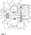
FIG. 4 is a schematic diagram of the appliance ofFIG. 2 showing the heat pump system in a drying condition; -
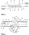
FIG. 5 is a schematic diagram illustrating an aspect of the second heat exchanger ofFIG. 4 shown in the drying condition; -
FIG. 6 is a schematic diagram illustrating an aspect of the third heat exchanger of the appliance disposed in the drying condition; -
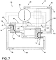
FIG. 7 is a schematic diagram illustrating a heat exchange system of the appliance ofFIG. 2 in the washing condition; -
FIG. 8 is a schematic diagram illustrating a heat exchange mechanism of the appliance ofFIG. 4 in the drying condition; and -
FIG. 9 is a schematic flow diagram illustrating a method for operating a combination washing and drying laundry appliance utilizing a reversible heat pump system. - For purposes of description herein the terms "upper," "lower," "right," "left," "rear," "front," "vertical," "horizontal," and derivatives thereof shall relate to the device as oriented in
FIG. 1 . However, it is to be understood that the device may assume various alternative orientations and step sequences, except where expressly specified to the contrary. It is also to be understood that the specific devices and processes illustrated in the attached drawings, and described in the following specification are simply exemplary embodiments of the inventive concepts defined in the appended claims. Hence, specific dimensions and other physical characteristics relating to the embodiments disclosed herein are not to be considered as limiting, unless the claims expressly state otherwise. - As illustrated in
FIGS. 1-8 ,reference numeral 10 generally refers to a reversibleheat pump system 10 for use in anappliance 12, such as a combination washing/drying laundry appliance 12. The reversibleheat pump system 10 for thelaundry appliance 12 can be used for transferringheat energy 14 from one portion of theappliance 12 to another portion of theappliance 12 for the performance of various temperature-related functions. These functions can include heating and/or cooling various materials within theappliance 12 such asprocess air 16,fluid 18, arefrigerant 20, and other similar thermal exchange materials. - According to the various embodiments, as exemplified in
FIGS. 1-6 , thelaundry appliance 12 can include a rotatingdrum 22 for receivingitems 24 to be processed.Such items 24 can include, but are not limited to, fabric, clothing, otherwearable items 24, and other similar things typically cleaned within thelaundry appliance 12. Anairflow path 26 is disposed within thelaundry appliance 12 and selectively directs a flow ofprocess air 16 across afirst heat exchanger 28 in adrying condition 30 and awashing condition 32. It is contemplated that thedrying condition 30 is defined by theprocess air 16 being directed through the rotatingdrum 22 and through a shower area in the form of athird heat exchanger 34. Thewashing condition 32 of theairflow path 26 is defined by theprocess air 16 being directed away from the rotatingdrum 22 and/or thethird heat exchanger 34. Thelaundry appliance 12 can also include afluid path 36 that selectively directsfluid 18 through asecond heat exchanger 38 in the drying andwashing conditions fluid path 36, thedrying condition 30 is further defined by thefluid 18 being selectively directed through thethird heat exchanger 34 to intersect with theprocess air 16. Thewashing condition 32 with respect to thefluid path 36 is further defined by thefluid 18 being selectively directed to the rotatingdrum 22. - Referring again to
FIGS. 1-8 , to operate the heat exchange functions of theappliance 12, areversible refrigerant circuit 50 is adapted to direct arefrigerant 20 between the first andsecond heat exchangers reversible refrigerant circuit 50 includes aflow control valve 52 that directs the flow of therefrigerant 20 in first andsecond directions washing conditions reversible refrigerant circuit 50, as well as the airflow andfluid paths reversible refrigerant circuit 50, thedrying condition 30 is defined by thefirst heat exchanger 28 being a heater, such as acondenser 58, for theprocess air 16 and thesecond heat exchanger 38 being a cooling module, such as anevaporator 60, for thefluid 18. Conversely, when thereversible refrigerant circuit 50 is reversed by theflow control valve 52, thewashing condition 32 is defined by thefirst heat exchanger 28 being the cooling module, orevaporator 60, for theprocess air 16 and thesecond heat exchanger 38 being a heater, orcondenser 58, for thefluid 18. It is contemplated that in thedrying condition 30, thefluid 18 and theprocess air 16 intersect with one another at thethird heat exchanger 34. In this manner, the moisture condensation andparticulate filtration mechanisms second heat exchangers reversible refrigerant circuit 50 is free of direct contact with thethird heat exchanger 34. This configuration serves to limit the amount ofparticulate matter 62 that adheres to the first andsecond heat exchangers drying condition 30. - Referring again to
FIGS. 4-6 , when thelaundry appliance 12 is in thedrying condition 30, thethird heat exchanger 34 defines aparticulate filtration mechanism 70 and simultaneously defines amoisture condensation mechanism 68. Through these mechanisms, thethird heat exchanger 34 is adapted to simultaneously removeparticulate matter 62 and condense and removemoisture 72 from theprocess air 16 as theheated process air 74 is mixed with the cooledfluid 76 within thethird heat exchanger 34. According to various embodiments, theparticulate filtration mechanism 70 and themoisture condensation mechanism 68 can be defined by afluid sprayer 78 that is disposed proximate thethird heat exchanger 34. Thefluid sprayer 78 is adapted to selectively shower or otherwise deliver the cooledfluid 76 from thesecond heat exchanger 38. In thedrying condition 30, thesecond heat exchanger 38 serves as a cooling module that extractsheat energy 14 from thefluid 18 as therefrigerant 20 changes phases within thesecond heat exchanger 38. Afterheat energy 14 is extracted from the fluid 18, the fluid 18 defines the cooledfluid 76 that is delivered to thefluid sprayer 78 of thethird heat exchanger 34. Thefluid sprayer 78 selectively delivers the cooledfluid 76 to intersect with aheated process air 74 delivered from thefirst heat exchanger 28. - Referring again to
FIGS. 4-6 , in the dryingcondition 30, thefirst heat exchanger 28 defines a heater, such as acondenser 58, wherebyheat energy 14 is radiated or otherwise given off from the refrigerant 20 within thefirst heat exchanger 28 and delivered to theprocess air 16 passing through theairflow path 26. Because theairflow path 26 is in direct communication with thefirst heat exchanger 28, theheat energy 14 radiated from the refrigerant 20 is delivered to theprocess air 16 to define theheated process air 74. Thisheated process air 74 is delivered through therotating drum 22 and then to thethird heat exchanger 34. As will be described more fully below, as theheated process air 74 passes through therotating drum 22,moisture 72 from damp orwet items 24 disposed within therotating drum 22 can be entrapped within theheated process air 74 to define moisture-laden process air 90. In addition tomoisture 72, the moisture-laden process air 90 can also accumulateparticulate matter 62 that is captured from theitems 24 being processed within therotating drum 22. Thisparticulate matter 62 is typically in the form of lint, fluff, other fibrous material, various particles, and other similarparticulate matter 62 typically seen withinlaundry drying appliances 12. - Referring again to
FIGS. 4-6 , as the moisture-laden process air 90 is delivered to thethird heat exchanger 34, the cooledfluid 76 is delivered from thefluid sprayer 78 and travels through the moisture-laden process air 90. The combination of the heated moisture-laden process air 90 and the cooledfluid 76 causes an exchange ofheat energy 14 from theprocess air 16 to the fluid 18 that cools and dehumidifies the moisture-laden process air 90. This exchange ofheat energy 14 causes a condensation and removal of the moisture within the moisture-laden process air 90, where this precipitatedmoisture 72 is captured by the cooledfluid 76. The cooledfluid 76 delivered from thefluid sprayer 78 also captures all or substantially all of theparticulate matter 62 contained within theprocess air 16. In this manner, theprocess air 16 leaving thethird heat exchanger 34 defines cooledreturn air 92, being substantially free ofparticulate matter 62, that is returned to thefirst heat exchanger 28 to be reheated for further performance of the various drying functions of theappliance 12. The fluid 18 leaving thethird heat exchanger 34 defines aheated return fluid 94 that contains the capturedmoisture 72 and capturedparticulate matter 62 from the moisture-laden process air 90. Theheated return fluid 94 is then delivered back toward afluid tank 96 and/or thesecond heat exchanger 38. Theparticulate matter 62 can be removed from theheated return fluid 94, and the fluid 18 is then cooled through thesecond heat exchanger 38 to be returned to thethird heat exchanger 34 for further filtration and condensing of additional moisture-laden process air 90. - Referring now to
FIGS. 2 and3 , thewashing condition 32 of theappliance 12 is defined by afluid diverter valve 110 within thefluid path 36 modifying the flow of the fluid 18 to be into therotating drum 22, rather than thethird heat exchanger 34. As discussed above, thewashing condition 32 of theappliance 12 is defined by thesecond heat exchanger 38, which is in communication with the fluid 18 and thefluid path 36, being a heater that is adapted to defineheated fluid 112 that is delivered to therotating drum 22. Accordingly, fluid 18 heated through the reversibleheat pump system 10 can be delivered to therotating drum 22 for addingheated fluid 112 to the combination washing/dryingappliance 12. Thefluid diverter valve 110 can be in the form of a two-way valve that alternates the flow of the fluid 18 between thethird heat exchanger 34 and therotating drum 22. - Referring again to
FIGS. 2 and3 , thewashing condition 32 of theappliance 12 is further defined by thefirst heat exchanger 28 being anevaporator 60 that is adapted to decrease the air temperature of theprocess air 16 of theairflow path 26 to define cooledprocess air 118. In thewashing condition 32, one of the functions of thefirst heat exchanger 28, being a cooling module in thewashing condition 32, is to removeheat energy 14 from the system for purposes of allowing thecondenser 58, in the form of thesecond heat exchanger 38, to properly heat thefluid 18 for delivery to therotating drum 22. To perform this function, theairflow path 26 includes anair diverting system 120 in the form of at least oneair deflector 122 that blocks theprocess air 16 from entering at least one of therotating drum 22 and thethird heat exchanger 34. Typically, theprocess air 16 in thewashing condition 32 will be redirected by theair deflectors 122 from entering either of therotating drum 22 or thethird heat exchanger 34. Accordingly, in thewashing condition 32, theairflow path 26 defines a generally linear andnon-recirculating airflow path 26 that delivers air through thefirst heat exchanger 28 in the form of anevaporator 60. Thisprocess air 16 is then cooled and delivered away from thefirst heat exchanger 28, typically out of theappliance 12 altogether. - It is contemplated that various aspects of the
appliance 12 can include a recirculation of the cooledprocess air 118 into another portion of theappliance 12. Such cooledprocess air 118 leaving theevaporator 60 in thewashing condition 32 can be used for cooling various portions of theappliance 12. Such cooling functions can include, but are not limited to, cooling acompressor 130 or making fine adjustments to thefluid temperature 132 of theheated fluid 112 leaving thesecond heat exchanger 38. It is also contemplated that the cooledprocess air 118 can be delivered to an area outside of theappliance 12 for cooling an area or a fixture proximate the combination washing/dryingappliance 12, or other similar cooling functions for a household and/or commercial cooling function. - Referring again to
FIGS. 2 and3 , in thewashing condition 32, asprocess air 16 is moved toward theevaporator 60, it is contemplated that a portion of theheated fluid 112 delivered to thedrum 22 can be used as asecondary fluid shower 140 for removingparticulate matter 62 that may be contained within theprocess air 16 as it approaches thefirst heat exchanger 28 in the form of theevaporator 60. This secondaryfluid shower 140 may also heat theprocess air 16, thereby providing theprocess air 16 with additional capacity for extracting heat from theevaporator 60. This additional capacity for extractingheat energy 14 from theevaporator 60 can serve to make the reversibleheat pump system 10 more efficient during its operation. Thesecondary fluid shower 140, in addition to potentially increasing the thermal capacity to acceptheat energy 14 from theevaporator 60, also removesparticulate matter 62 from theprocess air 16. In this manner,particulate matter 62 can be removed from theprocess air 16 before reaching thefirst heat exchanger 28. Thisparticulate matter 62 is thereby removed before theparticulate matter 62 can adhere to portions of theevaporator 60. Accordingly, thesecondary fluid shower 140 can serve as a secondaryparticulate filtration mechanism 70 for preventing the accumulation ofparticulate matter 62 on thefirst heat exchanger 28 in thewashing condition 32. - Referring again to
FIGS. 1-8 , in order to control the reversiblerefrigerant circuit 50, thefluid diverter valve 110 and theair diverting system 120, theappliance 12 can include acontrol 150 in communication with these components. It is contemplated that thecontrol 150 selectively and alternatively defines the washing and dryingconditions refrigerant circuit 50, thefluid path 36 and theairflow path 26. Accordingly, the washing and dryingconditions refrigerant circuit 50, thefluid path 36 and theairflow path 26 are in communication and collectively modified between the washing and dryingconditions control 150. - Referring again to
FIGS. 1-8 , according to the various embodiments, theairflow path 26 is adapted to be free of direct engagement with thesecond heat exchanger 38 at least in the dryingcondition 30 and typically in both the washing and dryingconditions fluid path 36 of theappliance 12 is adapted to be free of direct engagement with thefirst heat exchanger 28 in each of the washing and dryingconditions refrigerant circuit 50 is free of engagement with thethird heat exchanger 34. In the dryingcondition 30, it is contemplated that the reversiblerefrigerant circuit 50 is in indirect thermal communication with thethird heat exchanger 34 through operation of thefluid path 36 andairflow path 26, as described above during operation of the dryingcondition 30. - In the drying
condition 30, as exemplified inFIGS. 4-6 , it is contemplated that theairflow path 26, through operation of theair deflectors 122, defines arecirculating drying path 160 that recirculatesprocess air 16 from thefirst heat exchanger 28, through therotating drum 22 and through thethird heat exchanger 34, such that each of these components are positioned along therecirculating drying path 160. Alternatively, in thewashing condition 32, theairflow path 26 is modified through the one ormore air deflectors 122 to define a non-recirculatingcooling flow path 162 through thefirst heat exchanger 28 that carries theprocess air 16 away from therotating drum 22 and also away from thethird heat exchanger 34. - Referring again to
FIGS. 1-8 , an air/water handling system 170 can be disposed within theappliance 12. It is contemplated that the air/water handling system 170 can include therotating drum 22, and theairflow path 26 that includes ablower 172 for directingprocess air 16 through theairflow path 26. Afluid path 36 is included, where thefluid path 36 includes apump 174 for directing a fluid 18 through at least a portion of thefluid path 36. Thefirst heat exchanger 28 is positioned to be in direct engagement with theairflow path 26. Thesecond heat exchanger 38 is positioned to be in direct engagement with thefluid path 36. The reversiblerefrigerant circuit 50 serves to deliver a refrigerant 20 through the first andsecond heat exchangers refrigerant circuit 50 selectively and alternatively defines thewashing condition 32 where thefirst heat exchanger 28 is an evaporator 60 that cools theprocess air 16. As theprocess air 16 leaves theevaporator 60 of thefirst heat exchanger 28, thisprocess air 16 defines cooledprocess air 118. Thesecond heat exchanger 38, in thewashing condition 32, defines acondenser 58 that heats the fluid 18 to defineheated fluid 112 that is directed into therotating drum 22. The reversiblerefrigerant circuit 50 includes aflow control valve 52 that reverses the flow of the refrigerant 20 between the first andsecond directions conditions - In the drying
condition 30 of the reversiblerefrigerant circuit 50, thefirst heat exchanger 28 is acondenser 58 that heats theprocess air 16 to defineheated process air 74. Thisheated process air 74 is directed through therotating drum 22 and through thethird heat exchanger 34. Thesecond heat exchanger 38 in the dryingcondition 30 is defined as anevaporator 60. In the dryingcondition 30, theevaporator 60 serves to cool the fluid 18 to define the cooledfluid 76 that is directed to thethird heat exchanger 34. This cooledfluid 76 delivered to thethird heat exchanger 34 is adapted to intersect with theheated process air 74. Thethird heat exchanger 34 delivers the cooledfluid 76 to afluid sprayer 78 that directs the cooledfluid 76 through theheated process air 74, as described above. The cooledfluid 76 serves to decrease the air temperature of theheated process air 74 while also wetting and capturingparticulate matter 62 within theheated process air 74. Thewet particulate matter 62, being heavier, is allowed to fall from the moisture-laden process air 90 and is captured or wasted away with theheated return fluid 94. In this manner, the intermingling of the cooledfluid 76 with theheated process air 74 defines moisture condensation andparticulate filtration mechanisms third heat exchanger 34. Simultaneously, theheated process air 74 increases afluid temperature 132 of the cooledfluid 76. As theheat energy 14 is transferred from theheated process air 74 to the cooledfluid 76, the precipitation ofmoisture 72 occurs to condense and removemoisture 72 that may be contained within theheated process air 74 as it moves through thethird heat exchanger 34. - Referring now to
FIGS. 1-9 , having described various aspects of the combination washing/dryingappliance 12 that utilizes the reversibleheat pump system 10, amethod 400 is disclosed for operating a combination washing/dryinglaundry appliance 12. According to themethod 400, whereitems 24, such as fabric or clothing, are disposed in therotating drum 22 to be washed and dried by the washing and dryinglaundry appliance 12, thewashing condition 32 of theheat pump system 10 is activated (step 402). As discussed above, thewashing condition 32 is characterized by thefirst heat exchanger 28 defining anevaporator 60 that is adapted to be in direct engagement with theairflow path 26. Thewashing condition 32 of theairflow path 26 is defined by theair diverting system 120 to deliverprocess air 16 across thefirst heat exchanger 28 and away from therotating drum 22. As discussed above, theprocess air 16 in thewashing condition 32 is adapted to allow for the transfer ofheat energy 14 from theevaporator 60 to theprocess air 16 for expulsion away from theevaporator 60. Thewashing condition 32 is further characterized by thesecond heat exchanger 38 defining acondenser 58 coupled to thefirst heat exchanger 28 via the reversiblerefrigerant circuit 50. In thewashing condition 32, the refrigerant 20 of the reversiblerefrigerant circuit 50 is adapted to flow in afirst direction 54 through operation of theflow control valve 52. - According to the
method 400, after thewashing condition 32 is activated, a fluid 18 disposed within thefluid path 36 is heated (step 404). This fluid 18 can be delivered to thefluid path 36 via an external fluid source such as a wall spigot. Alternatively, the fluid 18 within thefluid path 36 can be stored fluid 18 from a previous laundry cycle that can be recirculated for use in subsequent laundry cycles. It is contemplated that thesecond heat exchanger 38, being acondenser 58 in thewashing condition 32, heats the fluid 18 to a predetermined temperature. - According to the various embodiments, it is contemplated that the
condenser 58 in thewashing condition 32 can be adapted to heat the fluid 18 to a certain temperature according to each performance of thewashing condition 32. Thisheated fluid 112 can then be mixed with cool external tap water or cooled and stored water to achieve a particular temperature. It is also contemplated that the fluid 18 can be moved through thecondenser 58 at a particular rate, such that a predetermined rate of heating is experienced by the fluid 18 moving through thecondenser 58 in order to achieve a predetermined temperature. - By way of example, and not limitation, fluid 18 moving slowly through the
condenser 58 may receive greater amounts ofheat energy 14 from thecondenser 58 and therefore reach a higherpredetermined fluid temperature 132. Conversely, fluid 18 moving through thecondenser 58 at a faster rate may receive lesser amounts ofheat energy 14 and may therefore achieve a lesser orlower fluid temperature 132. In this manner, the operation of thefluid pump 174 can vary the flow rate of the fluid 18 to also vary thefluid temperature 132 of theheated fluid 112. - Referring again to
FIGS. 1-9 , once the fluid 18 is heated, theheated fluid 112 is delivered to the rotating drum 22 (step 406). Theheated fluid 112 enters therotating drum 22 and soaks the one ormore items 24 disposed within therotating drum 22. It is contemplated that during aparticular washing condition 32, theheated fluid 112 can be mixed withvarious washing fluids 18, such as detergent, fabric softener, bleach, oxi-substances, and other laundry-related products. Theheated fluid 112 and various laundry-related products serve to soak the at least one item within therotating drum 22. After being soaked,various washing conditions 32 are performed with respect to the at least one item within the rotating drum 22 (step 408). As thewashing condition 32 is performed, the at least one item becomes adamp item 180 disposed within therotating drum 22. - It is contemplated that the
washing condition 32 can include various washing cycles. These washing cycles can include, but are not limited to, agitation cycles, rinse cycles, spin cycles, steaming cycles, sanitizing cycles, soak cycles, and other similar washing-related laundry cycles. In the case of a steam-washing cycle, the fluid 18 can be moved through thecondenser 58 at a particularly slow rate such that at least a portion of the fluid 18 is heated to above the boiling point of water to achieve a gaseous state (i.e., steam). This gaseous form of a portion of theheated fluid 112 can be injected into therotating drum 22 for the performance of various sanitizing functions of thelaundry appliance 12. After the various washing cycles are completed, thewashing condition 32 of theheat pump system 10 is deactivated (step 410). - Referring again to
FIGS. 1-9 , according to themethod 400, after thewashing condition 32 is complete, the flow of the refrigerant 20 in the reversible refrigerant cycle is reversed from thefirst direction 54 to thesecond direction 56 through operation of the flow control valve 52 (step 412). The flow ofrefrigerant 20 in thesecond direction 56 activates the dryingcondition 30 of theheat pump system 10. As discussed above, the dryingcondition 30 of theheat pump system 10 is characterized by thefirst heat exchanger 28 being acondenser 58 that is in direct engagement with theairflow path 26. Additionally, theairflow path 26 defines a recirculating path that deliversprocess air 16 through therotating drum 22, thethird heat exchanger 34 and thefirst heat exchanger 28, sequentially. Thesecond heat exchanger 38 in the dryingcondition 30 defines anevaporator 60 in direct engagement with thefluid path 36, where thefluid path 36 defines a recirculating path that delivers the fluid 18 from thesecond heat exchanger 38 to thefluid sprayer 78 of thethird heat exchanger 34. - According to the
method 400, during operation of the dryingcondition 30,process air 16 is delivered to thefirst heat exchanger 28 to define heated process air 74 (step 414). Thisheated process air 74 is then delivered to the at least onedamp item 180 within therotating drum 22. Theheated process air 74 mingles with thedamp item 180 to capture at least a portion of themoisture 72 and a portion of theparticulate matter 62 from thedamp item 180 to define moisture-laden process air 90 that is then delivered out of therotating drum 22. The moisture-laden process air 90 is then delivered to the third heat exchanger 34 (step 416). - Referring again to
FIGS. 1-9 , simultaneous, or substantially simultaneous to the formation of theheated process air 74, cooledfluid 76 is formed by delivering at least a portion of the fluid 18 through thesecond heat exchanger 38 in the form of the evaporator 60 (step 418). This cooledfluid 76 is then delivered to thefluid sprayer 78 of the third heat exchanger 34 (step 420). Within thethird heat exchanger 34, the cooledfluid 76 is sprayed through the moisture-laden process air 90 as the moisture-laden process air 90 moves through the third heat exchanger 34 (step 422). - According to the various embodiments, as exemplified in
FIGS. 1-9 , within thethird heat exchanger 34, the cooledfluid 76 decreases the air temperature of a moisture-laden process air 90 to condense and precipitate at least a portion of themoisture 72 therefrom and also capture at least a portion of theparticulate matter 62. Accordingly, the cooled fluid 76 changes the moisture-laden process air 90 into cooledreturn air 92 that has a lower amount ofmoisture 72 and also little, if any,particulate matter 62 contained therein. The moisture-laden process air 90 also serves to increase the temperature of the cooledfluid 76 to define aheated return fluid 94. Theheated return fluid 94 contains at least a portion of themoisture 72 andparticulate matter 62 from the moisture-laden process air 90 that was included therein. - According to the
method 400, after the heat exchange operation within thethird heat exchanger 34, the cooledreturn air 92 is returned through theairflow path 26 back to the first heat exchanger 28 (step 424). In this manner, the cooledreturn air 92 is returned to thefirst heat exchanger 28 and is substantially free ofparticulate matter 62. In this manner, thethird heat exchanger 34 serves as aparticulate filtration mechanism 70 that removesparticulate matter 62 from theprocess air 16. Thisparticulate matter 62 is then retained within theheated return fluid 94. In this manner,particulate matter 62 does not adhere or substantially adhere to or become entrapped within thefirst heat exchanger 28 during operation of the dryingcondition 30. Theheated return fluid 94,moisture 72 andparticulate matter 62 are returned to a fluid tank 96 (step 426). - According to the various embodiments, as exemplified in
FIGS. 1-9 , it is contemplated that theheated return fluid 94 andmoisture 72 can be recirculated across thesecond heat exchanger 38 for re-use as cooledfluid 76 for delivery back to thethird heat exchanger 34. Thefluid tank 96 can include a particulate removal system that entraps and removesparticulate matter 62 removed from the moisture-laden process air 90. This entrappedparticulate matter 62 can ultimately be expelled from theappliance 12 and through a drain pump and/ordrain outlet 190 for removal from theappliance 12. After an appropriate amount ofmoisture 72 has been removed from thedamp item 180 within therotating drum 22, the dryingcondition 30 is completed (step 428). The fluid 18,moisture 72 andparticulate matter 62 can thereby be delivered to adrain outlet 190 for expulsion from theappliance 12. As discussed above, it is contemplated that, in various embodiments, the fluid 18 andmoisture 72 can be recirculated for use in a later washing cycle. - Through the use of the reversible
heat pump system 10 used in conjunction with the first, second andthird heat exchangers third heat exchangers process air 16 andfluid 18. Theheat energy 14 transferred through the first andsecond heat exchangers appliance 12 for performing various filtration, condensation, washing and drying functions of theappliance 12. Through the use of this reversibleheat pump system 10,particulate matter 62 is maintained separate from the first andsecond heat exchangers particulate matter 62 does not become entrapped within the coil structures first andsecond heat exchangers particulate matter 62 is removed through the intermingling ofprocess air 16 andfluid 18 within thethird heat exchanger 34. While theparticulate matter 62 is removed at a location physically separated from the first andsecond heat exchangers heat energy 14 transferred between the first andsecond heat exchangers third heat exchanger 34. Accordingly, delivery ofheat energy 14 through the first, second andthird heat exchangers conditions appliance 12. - According to the various embodiments, this
particulate matter 62 is removed and remains separate from the first andsecond heat exchangers particulate matter 62 from the various systems of theappliance 12. - According to the various embodiments, it is contemplated that the reversible
refrigerant circuit 50 can be any one of various refrigerant circuits. By way of example, and not limitation, the reversiblerefrigerant circuit 50 can include acompressor 130, expansion device, refrigerant line with the refrigerant 20 disposed therein, and aflow control valve 52 that serves to reverse the flow ofrefrigerant 20 through the refrigerant line. The refrigerant 20 contained within the reversiblerefrigerant circuit 50 can include, but are not limited to, Freon, water, and other similar phase change materials that can be used within various refrigeration and/orheat pump systems 10.
Claims (15)
- A laundry appliance (12) comprising:a rotating drum (22) for receiving items (24) to be processed;an airflow path (26) that selectively directs a flow of process air (16) across a first heat exchanger (28) in a drying condition (30) and a washing condition (32), wherein the drying condition (30) is defined by the process air (16) being directed through the rotating drum (22) and through a third heat exchanger (34), and the washing condition (32) is defined by the process air (16) being directed away from the third heat exchanger (34);a fluid path (36) that selectively directs fluid (18) through a second heat exchanger (38) in the drying and washing conditions (30, 32), the drying condition (30) further defined by the fluid (18) being selectively directed through the third heat exchanger (34) to intersect with the process air (16), and the washing condition (32) further defined by the fluid (18) being selectively directed to the rotating drum (22); anda reversible heat exchange circuit (50) that further defines the drying and washing conditions (30, 32), the drying condition (30) defined by the first heat exchanger (28) being a heater for the process air (16) and the second heat exchanger (38) being a cooling module for the fluid (18), the washing condition (32) defined by the first heat exchanger (28) being a cooling module for the process air (16) and the second heat exchanger (38) being a heater for the fluid (18), wherein the fluid (18) and the process air (16) intersect with one another at the third heat exchanger (34) in the drying condition (30).
- The laundry appliance (12) of claim 1, wherein the third heat exchanger (34) in the drying condition (30) defines a filtration and moisture condensation mechanism (68) for removing moisture (72) and particulate matter (62) from the process air (16) within the third heat exchanger (34).
- The laundry appliance (12) of claim 2, wherein the filtration and moisture condensation mechanism (68) is defined by a fluid sprayer (78) proximate the third heat exchanger (34), the fluid sprayer (78) selectively delivering cooled fluid (76) from the second heat exchanger (38) to intersect with a heated process air (16) from the first heat exchanger (28).
- The laundry appliance (12) of any one or more of claims 1-3, further comprising:a control (150) in communication with the reversible heat exchange circuit (50), wherein the control (150) is also in communication with a fluid diverter valve (110) of the fluid path (36) and an air diverting system (120) of the airflow path (26) to selectively and alternatively define the washing and drying conditions (32, 30) in each of the reversible heat exchange circuit (50), the fluid path (36) and the airflow path (26).
- The laundry appliance (12) of any one or more of claims 1-4, wherein the reversible heat exchange circuit (50), the fluid path (36) and the airflow path (26) are in communication to be collectively modified between the washing and drying conditions (32, 30).
- The laundry appliance (12) of any one or more of claims 1-5, wherein the airflow path (26) is free of direct engagement with the second heat exchanger (38) at least in the drying condition (30), the fluid path (36) is free of direct engagement with the first heat exchanger (28) in each of the washing and drying conditions (32, 30), and the reversible heat exchange circuit (50) is free of engagement with the third heat exchanger (34).
- The laundry appliance (12) of any one or more of claims 4-6, wherein the air diverting system (120) is defined by at least one air deflector (122) operable within the airflow path (26) that is operable within the airflow path (26) to define the washing and drying conditions (32, 30).
- The laundry appliance (12) of claim 7, wherein the at least one air deflector (122) in the drying condition (30) defines a recirculating drying path (160) with each of the rotating drum (22), the third heat exchanger (34) and the first heat exchanger (28) being positioned along the recirculating drying path (160).
- The laundry appliance (12) of any one or more of claims 2-8, wherein the at least one air deflector (122) in the washing condition (32) defines a non-recirculating cooling flow path (162) through the first heat exchanger (28) that carries process air (16) away from the rotating drum (22).
- The laundry appliance (12) of any one or more of claims 1-9, wherein the reversible heat exchange circuit (50) is a reversible refrigerant circuit (50) that directs a refrigerant (20) between the first and second heat exchangers (28, 38).
- The laundry appliance (12) of claim 10, wherein the reversible refrigerant circuit (50) having a flow control valve (52) that further defines the drying and washing conditions (30, 32) of the reversible refrigerant circuit (50).
- The laundry appliance (12) of any one or more of claims 3-11, wherein the third heat exchanger (34) is a shower area, wherein in response to the intersection of the heated process air (16) and the cooled fluid (76) in the shower area, the heated process air (16) is dehumidified and cooled by the cooled fluid (76) and the cooled fluid (76) is heated by the heated process air (16).
- The laundry appliance (12) of any one or more of claims 1-12, wherein the airflow path (26) includes a blower (172) for directing the flow of process air (16), and wherein the fluid path (36) includes a fluid pump (174) that selectively directs the fluid (18).
- The laundry appliance (12) of any one or more of claims 1-13, wherein the a first heat exchanger (28) is in direct engagement with the process air (16) within the airflow path (26).
- The laundry appliance (12) of any one or more of claims 1-14, wherein the second heat exchanger (38) is in direct engagement with the fluid (18) within the fluid path (36).
Applications Claiming Priority (1)
| Application Number | Priority Date | Filing Date | Title |
|---|---|---|---|
| US15/293,813 US10519591B2 (en) | 2016-10-14 | 2016-10-14 | Combination washing/drying laundry appliance having a heat pump system with reversible condensing and evaporating heat exchangers |
Publications (2)
| Publication Number | Publication Date |
|---|---|
| EP3309293A1 true EP3309293A1 (en) | 2018-04-18 |
| EP3309293B1 EP3309293B1 (en) | 2019-06-26 |
Family
ID=60117550
Family Applications (1)
| Application Number | Title | Priority Date | Filing Date |
|---|---|---|---|
| EP17196494.3A Not-in-force EP3309293B1 (en) | 2016-10-14 | 2017-10-13 | Combination washing/drying laundry appliance having a heat pump system with reversible condensing and evaporating heat exchangers |
Country Status (2)
| Country | Link |
|---|---|
| US (3) | US10519591B2 (en) |
| EP (1) | EP3309293B1 (en) |
Cited By (4)
| Publication number | Priority date | Publication date | Assignee | Title |
|---|---|---|---|---|
| EP3792387A1 (en) * | 2019-09-10 | 2021-03-17 | Johannes Guggenberger | Condensate heat exchanger |
| WO2023186282A1 (en) * | 2022-03-30 | 2023-10-05 | Electrolux Appliances Aktiebolag | Top module for a laundry treatment machine with heat pump |
| WO2023186286A1 (en) * | 2022-03-30 | 2023-10-05 | Electrolux Appliances Aktiebolag | Laundry treatment method and machine using a heat pump with an evaporator regeneration |
| EP4411056A1 (en) * | 2023-01-31 | 2024-08-07 | Whirlpool Corporation | Combination laundry appliance with heat pump assembly |
Families Citing this family (7)
| Publication number | Priority date | Publication date | Assignee | Title |
|---|---|---|---|---|
| CN111743482B (en) * | 2019-03-29 | 2024-11-22 | 佛山市顺德区美的洗涤电器制造有限公司 | Drying units and dishwashers |
| US11851807B2 (en) | 2019-11-07 | 2023-12-26 | Whirlpool Corporation | Method of removing heat from a clothes tumbling system on the outside of the cabinet |
| US12410552B2 (en) * | 2021-05-17 | 2025-09-09 | Whirlpool Corporation | Three-dimensional steam generating system for performing a steam cycle within a laundry appliance |
| WO2023186283A1 (en) * | 2022-03-30 | 2023-10-05 | Electrolux Appliances Aktiebolag | Laundry treatment method and machine using a heat pump with an evaporator regeneration |
| WO2023186281A1 (en) * | 2022-03-30 | 2023-10-05 | Electrolux Appliances Aktiebolag | Laundry treatment machine with heat pump |
| WO2023186276A1 (en) * | 2022-03-30 | 2023-10-05 | Electrolux Appliances Aktiebolag | Laundry treatment machine with heat pump |
| WO2023186278A1 (en) * | 2022-03-30 | 2023-10-05 | Electrolux Appliances Aktiebolag | Laundry treatment machine with heat pump |
Citations (2)
| Publication number | Priority date | Publication date | Assignee | Title |
|---|---|---|---|---|
| EP2189568A1 (en) * | 2008-11-21 | 2010-05-26 | Electrolux Home Products Corporation N.V. | Laundry washing and drying machine |
| EP3034675A1 (en) * | 2014-12-17 | 2016-06-22 | Miele & Cie. KG | Device and method for heating a treatment liquid for a laundry treatment device and laundry treatment device |
Family Cites Families (239)
| Publication number | Priority date | Publication date | Assignee | Title |
|---|---|---|---|---|
| US2515825A (en) | 1945-03-16 | 1950-07-18 | Carrier Corp | Single stage refrigeration utilizing holdover means |
| US2873041A (en) | 1956-12-03 | 1959-02-10 | Carrier Corp | Breaker strip construction |
| US2934023A (en) | 1956-12-31 | 1960-04-26 | Murray Corp | Centrifugal pumps |
| US3196553A (en) | 1960-09-19 | 1965-07-27 | Gen Motors Corp | Temperature responsive timer control for a clothes drier |
| US3342961A (en) | 1960-09-19 | 1967-09-19 | Gen Motors Corp | Thermostat having thermally responsive means for arresting the movement of one of the contacts upon cooling of the thermostat |
| US3218730A (en) | 1962-06-14 | 1965-11-23 | Gen Motors Corp | Termination control for a condensing clothes dryer |
| US3653807A (en) | 1970-08-24 | 1972-04-04 | Whirlpool Co | Method and means for shredding and filtering lint in a washing machine |
| US3805404A (en) | 1973-07-02 | 1974-04-23 | I Gould | Water cooled condenser dryer for laundry center |
| US3953146A (en) | 1974-08-15 | 1976-04-27 | Whirlpool Corporation | Apparatus for treating lint in an automatic washer |
| US3999304A (en) | 1975-07-18 | 1976-12-28 | Doty Edward E | Clothes dryer filter and exhaust system |
| US4137647A (en) | 1977-09-06 | 1979-02-06 | Clark Jr James N | Heat and humidity recovery device for use with clothes dryer |
| US4134518A (en) | 1978-01-23 | 1979-01-16 | Bernie Menchen | Cold box with breaker strip |
| NL7801958A (en) | 1978-02-21 | 1979-08-23 | Zephyr Koel En Luchttechniek B | Refrigerated transport container system - has secondary circuit with pump and containing liq. refrigerating agent |
| GB2087029A (en) | 1980-09-19 | 1982-05-19 | Heat Pumps W R Ltd | Improvements in or Relating to Heat Exchangers |
| DE3147796A1 (en) | 1981-08-18 | 1983-03-03 | Spraytech AB, 18400 Åkersberga | Device for cleaning the warm exhaust air of a linen drier |
| US4860921A (en) | 1984-05-09 | 1989-08-29 | Edward Gidseg | Thermal breaker strip for refrigeration cabinets |
| US4603489A (en) | 1984-10-05 | 1986-08-05 | Michael Goldberg | Heat pump closed loop drying |
| US4870735A (en) | 1987-07-31 | 1989-10-03 | White Consolidated Industries, Inc. | Refrigeration cabinet construction |
| DE3738031C2 (en) | 1987-11-09 | 1995-10-12 | Bosch Siemens Hausgeraete | Method and device for removing lint from a condensate separator designed as a heat exchanger |
| IT1243685B (en) | 1990-07-24 | 1994-06-21 | Eurodomestici Ind Riunite | DEVICE FOR THE CLEANING OF AN EVAPORATOR, PROVIDED FOR IN A MACHINE-DRYER OR SIMILAR, FROM ELEMENTS RELEASED BY CLOTHING OR SIMILAR PRESENT IN THE BASKET OF SUCH MACHINE |
| KR950001350B1 (en) | 1992-02-25 | 1995-02-17 | 동양매직 주식회사 | Washing machine |
| DE4304372A1 (en) | 1993-02-13 | 1994-08-18 | Miele & Cie | Drying appliance, especially condensation-type laundry dryer, with a heat pump |
| DE4409607C2 (en) | 1993-04-21 | 2002-03-14 | Miele & Cie | Condensation clothes dryer with a heat pump |
| US5628122A (en) | 1994-10-05 | 1997-05-13 | Peter And Theordore Spinardi Investments | Lint remover for a clothes drying machine |
| US5720536A (en) | 1995-03-27 | 1998-02-24 | General Electric Company | Refrigerator with improved breaker strip assembly |
| IT1284443B1 (en) | 1996-06-26 | 1998-05-21 | Candy Spa | DOMESTIC WASHING MACHINE WITH CLOSED DRYING CIRCUIT, AIR CONDENSATION OF THE STEAM AND SELF-CLEANING FILTER |
| US5666817A (en) | 1996-12-10 | 1997-09-16 | Edward R. Schulak | Energy transfer system for refrigerator/freezer components |
| US5927095A (en) | 1997-05-20 | 1999-07-27 | Lg Electronics, Inc. | Anti-frost device for refrigerators |
| JP4018238B2 (en) | 1997-05-27 | 2007-12-05 | エルジー エレクトロニクス インコーポレイティド | Cold air supply system for refrigerator |
| DE69832212T2 (en) | 1997-05-28 | 2006-07-20 | Lg Electronics Inc. | fridge |
| KR100223225B1 (en) | 1997-08-28 | 1999-10-15 | 구자홍 | Refrigerator room temperature control method and apparatus |
| KR100254409B1 (en) | 1997-08-29 | 2000-05-01 | 구자홍 | Circulator for cooling air |
| KR100288261B1 (en) | 1998-06-30 | 2001-05-02 | 전주범 | Dew device of refrigerator |
| EP0999302B1 (en) | 1998-10-21 | 2003-08-20 | Whirlpool Corporation | Tumble dryer with a heat pump |
| ATE247735T1 (en) | 1999-04-30 | 2003-09-15 | Bsh Bosch Siemens Hausgeraete | METHOD FOR CLEANING THE PROCESS AIR LINE OF A DOMESTIC LAUNDRY DRYER AND A HOUSEHOLD LAUNDRY DRYER SET UP TO PERFORM THIS METHOD |
| DE10002742C1 (en) | 2000-01-22 | 2001-06-28 | Whirlpool Co | Heat pump washer-dryer has channel wall forming or carrying removable condensate collection unit, adjustable cleaning device near heat exchanger inlet removing adhering fluff |
| DE10002743B4 (en) | 2000-01-22 | 2006-01-12 | Whirlpool Corp., Benton Harbor | Heat pump tumble dryer with cleaning device for the heat exchanger |
| DE20001253U1 (en) | 2000-01-25 | 2001-06-07 | Liebherr-Hausgeräte GmbH, 88416 Ochsenhausen | Refrigerator with a refrigerator, a cold storage and a freezer compartment |
| CA2355155C (en) | 2000-08-16 | 2009-10-13 | Lg Electronics Inc. | Door cooling apparatus for refrigerator with double-acting door |
| JP4028688B2 (en) | 2001-03-21 | 2007-12-26 | 株式会社東芝 | refrigerator |
| DE10116238B4 (en) | 2001-03-31 | 2005-03-10 | Whirlpool Co | Clothes dryer with heat pump |
| US6983615B2 (en) | 2001-07-16 | 2006-01-10 | Maytag Corporation | French door chiller compartment for refrigerators |
| DE10140005A1 (en) | 2001-08-16 | 2003-02-27 | Bsh Bosch Siemens Hausgeraete | Combination refrigerator and evaporator arrangement therefor |
| DE10143242A1 (en) | 2001-09-04 | 2003-03-20 | Bsh Bosch Siemens Hausgeraete | Refrigeration device with cooling air circulation |
| NZ534444A (en) | 2002-02-22 | 2006-02-24 | Multibras S | |
| JP2004053055A (en) | 2002-07-17 | 2004-02-19 | Sanyo Electric Co Ltd | Refrigerator |
| US6973799B2 (en) | 2002-08-27 | 2005-12-13 | Whirlpool Corporation | Distributed refrigeration system for a vehicle |
| KR100487329B1 (en) | 2002-10-10 | 2005-05-03 | 엘지전자 주식회사 | Condensing Type Clothes Drier and Controlling the Same |
| JP3696224B2 (en) | 2003-03-19 | 2005-09-14 | 株式会社グリーンセイジュ | Drying system |
| BR0301406A (en) | 2003-04-15 | 2004-12-07 | Multibras Eletrodomesticos Sa | Arrangement for forced air circulation in refrigerators and freezers |
| US7168274B2 (en) | 2003-05-05 | 2007-01-30 | American Dryer Corporation | Combination washer/dryer having common heat source |
| NZ526361A (en) | 2003-05-30 | 2006-02-24 | Fisher & Paykel Appliances Ltd | Compressor improvements |
| US6793010B1 (en) | 2003-06-06 | 2004-09-21 | Tecumseh Products Company | Heat exchanger having non-perpendicularly aligned heat transfer elements |
| JP2005027768A (en) | 2003-07-09 | 2005-02-03 | Mitsubishi Electric Corp | Clothes dryer |
| KR100565622B1 (en) | 2003-09-19 | 2006-03-30 | 엘지전자 주식회사 | Refrigerator |
| US20070051127A1 (en) | 2003-09-26 | 2007-03-08 | Ssw Holding Company, Inc. | Cooling tubes for shelving |
| RU2006114770A (en) | 2003-09-29 | 2007-11-10 | Селф Пропеллед Рисерч энд Дивелопмент Спешелистс,эЛэЛСи (US) | DRYING DEVICE (OPTIONS), WASHING DEVICE AND DRYING CHAMBER (OPTIONS) |
| EP1548380A3 (en) | 2003-12-22 | 2006-10-04 | Hussmann Corporation | Flat-tube evaporator with micro-distributor |
| EP1564325B1 (en) | 2004-02-10 | 2018-04-11 | Electrolux Home Products Corporation N.V. | Improved clothes drying machine with clothes smoothing ability |
| KR100531834B1 (en) | 2004-04-06 | 2005-11-30 | 엘지전자 주식회사 | Exhaustion type clothes dryer with air inlet guide |
| US7281387B2 (en) | 2004-04-29 | 2007-10-16 | Carrier Commercial Refrigeration Inc. | Foul-resistant condenser using microchannel tubing |
| JP2006017338A (en) | 2004-06-30 | 2006-01-19 | Toshiba Corp | refrigerator |
| US7421846B2 (en) | 2004-08-18 | 2008-09-09 | Ice Energy, Inc. | Thermal energy storage and cooling system with gravity fed secondary refrigerant isolation |
| KR100738714B1 (en) | 2004-12-10 | 2007-07-12 | 엘지전자 주식회사 | Drying Washer |
| JP2006187449A (en) | 2005-01-06 | 2006-07-20 | Toshiba Corp | Washing and drying machine |
| US7775065B2 (en) | 2005-01-14 | 2010-08-17 | General Electric Company | Methods and apparatus for operating a refrigerator |
| US20080307823A1 (en) | 2005-02-01 | 2008-12-18 | Lg Electronics Inc. | Refrigerator |
| JP4834342B2 (en) | 2005-07-26 | 2011-12-14 | 株式会社東芝 | Drum type washer / dryer |
| KR100925908B1 (en) | 2005-07-28 | 2009-11-09 | 샤프 가부시키가이샤 | Drum type drying and washing machine |
| DE102005035652A1 (en) | 2005-07-29 | 2007-02-01 | BSH Bosch und Siemens Hausgeräte GmbH | Heat exchanger device for a tumble dryer |
| KR100661663B1 (en) | 2005-08-12 | 2006-12-26 | 삼성전자주식회사 | Refrigerator and its control method |
| KR101137335B1 (en) | 2005-08-25 | 2012-04-19 | 엘지전자 주식회사 | operating method for laundry machine |
| DE102005041145A1 (en) | 2005-08-29 | 2007-03-01 | Alpha-Innotec Gmbh | Laundry dryer, has heat pump heating system comprising compressor with changeable output, and controller controlling and/or regulating output of compressor based on residual moisture in laundry that is to be dried |
| US9663894B2 (en) | 2005-11-10 | 2017-05-30 | Lg Electronics Inc. | Steam generator and laundry dryer having the same and controlling method thereof |
| JP4661590B2 (en) | 2005-12-27 | 2011-03-30 | パナソニック株式会社 | Motor drive device for washing and drying machine |
| DE102005062940A1 (en) | 2005-12-29 | 2007-07-05 | BSH Bosch und Siemens Hausgeräte GmbH | A method for drying washing has a heat pump by which circulated air through the washing chamber is dried and heated and an additional heat pump evaporator is arranged to predry the circulated air stream |
| DE102006007420A1 (en) | 2006-02-17 | 2007-08-30 | BSH Bosch und Siemens Hausgeräte GmbH | Cleaning device for a component within a process air cycle of a household laundry drier |
| DE102006007443A1 (en) | 2006-02-17 | 2007-08-23 | BSH Bosch und Siemens Hausgeräte GmbH | Cleaning device for a component of a household laundry drier |
| DE102006018469A1 (en) | 2006-04-19 | 2007-10-25 | Lare Luft- und Kältetechnik Apparate und Regelsysteme GmbH | Cloth drier comprises a replaceable or cleanable water filter, electric control with a program for controlling a pump and a component for opening and closing a flow pipeline, heat pump system, aerator, condenser, compressor and evaporator |
| EP1852539B1 (en) | 2006-05-02 | 2010-07-14 | Electrolux Home Products Corporation N.V. | Drying program with anti-crease phase and dryer |
| KR100783211B1 (en) | 2006-07-19 | 2007-12-06 | 엘지전자 주식회사 | Valve assembly for preventing leakage of refrigerant in refrigerator |
| US7610773B2 (en) | 2006-12-14 | 2009-11-03 | General Electric Company | Ice producing apparatus and method |
| DE102006061211A1 (en) | 2006-12-22 | 2008-06-26 | BSH Bosch und Siemens Hausgeräte GmbH | Method for removing lint from a heat exchanger of a domestic appliance, and corresponding domestic appliance |
| DE102006061737B3 (en) | 2006-12-28 | 2008-04-24 | BSH Bosch und Siemens Hausgeräte GmbH | Condensing dryer has fan driven circuit for processing air and a heat pump circuit with a secondary fluid circuit between them |
| DE102007002181B3 (en) | 2007-01-15 | 2008-08-21 | BSH Bosch und Siemens Hausgeräte GmbH | Condensation dryer with a heat pump |
| KR100820151B1 (en) | 2007-02-20 | 2008-04-08 | 엘지전자 주식회사 | Ductless dryer |
| DE102007012071A1 (en) | 2007-03-13 | 2008-09-18 | BSH Bosch und Siemens Hausgeräte GmbH | Washer dryer with improved lint removal and process for its operation |
| DE102007016074A1 (en) | 2007-04-03 | 2008-10-09 | BSH Bosch und Siemens Hausgeräte GmbH | Method and device for cleaning a component, in particular an evaporator of a condenser device, and laundry or tumble dryer with such a device |
| CN101324389B (en) | 2007-06-13 | 2011-11-09 | 博西华家用电器有限公司 | Condenser combination and household electrical appliance using the same |
| EP2203585B1 (en) | 2007-09-04 | 2017-08-16 | LG Electronics Inc. | Dehumidifying apparatus for dryer |
| DE102007052835A1 (en) | 2007-11-06 | 2009-05-07 | BSH Bosch und Siemens Hausgeräte GmbH | Method and device for cleaning a component, in particular an evaporator of a condenser device, and laundry or tumble dryer with such a device |
| DE102007060854A1 (en) | 2007-12-18 | 2009-06-25 | BSH Bosch und Siemens Hausgeräte GmbH | Cleaning device for a component loaded with lint in a domestic appliance, and domestic appliance and method for cleaning a component loaded with lint |
| EP2225528B1 (en) | 2007-12-18 | 2011-09-07 | A-Heat AlliedHeat Exchange Technology AG | Heat exchange system |
| DE102007060851A1 (en) | 2007-12-18 | 2009-06-25 | BSH Bosch und Siemens Hausgeräte GmbH | Household appliance for the care of laundry items and method for removing lint |
| JP2011506903A (en) | 2007-12-18 | 2011-03-03 | アー − ヒート アライド ヒート イクスチェンジ テクノロジー アクチェンゲゼルシャフト | Heat exchanger |
| US8806886B2 (en) | 2007-12-20 | 2014-08-19 | General Electric Company | Temperature controlled devices |
| US8099975B2 (en) | 2007-12-31 | 2012-01-24 | General Electric Company | Icemaker for a refrigerator |
| WO2009089460A2 (en) | 2008-01-09 | 2009-07-16 | International Mezzo Technologies, Inc. | Corrugated micro tube heat exchanger |
| DE102008007971A1 (en) | 2008-02-07 | 2009-08-13 | BSH Bosch und Siemens Hausgeräte GmbH | Condensation dryer with heat pump and heater and method for its operation |
| CA2629470A1 (en) | 2008-04-18 | 2009-10-18 | Mabe Canada Inc. | Clothes dryer with thermal insulation pad |
| US8794026B2 (en) | 2008-04-18 | 2014-08-05 | Whirlpool Corporation | Secondary cooling apparatus and method for a refrigerator |
| DE102008020351A1 (en) | 2008-04-23 | 2009-10-29 | Valeo Klimasysteme Gmbh | Method for operating an air conditioning system for a motor vehicle |
| DE102008020556A1 (en) | 2008-04-24 | 2009-10-29 | BSH Bosch und Siemens Hausgeräte GmbH | Exhaust air dryer with reduced condensate formation and method for its operation |
| PL2138627T3 (en) | 2008-06-27 | 2017-01-31 | BSH Hausgeräte GmbH | Dryer comprising a heat sink and a condensate container |
| DE102008032800A1 (en) | 2008-07-11 | 2010-01-14 | BSH Bosch und Siemens Hausgeräte GmbH | Device for cleaning a component, in particular an evaporator of a capacitor device |
| DE102008033388B4 (en) | 2008-07-16 | 2020-07-16 | BSH Hausgeräte GmbH | Dryer with heat pump circuit |
| US8104191B2 (en) | 2008-07-31 | 2012-01-31 | Electrolux Home Products, Inc. | Laundry dryer providing moisture application during tumbling and reduced airflow |
| DE102008040946A1 (en) | 2008-08-01 | 2010-02-04 | BSH Bosch und Siemens Hausgeräte GmbH | Condensation dryer with a heat pump and detection of an impermissible operating state and method for its operation |
| DE102008041998A1 (en) | 2008-09-11 | 2010-03-18 | BSH Bosch und Siemens Hausgeräte GmbH | Dryer with a lint filter and a cleaning device |
| KR101549861B1 (en) | 2008-09-16 | 2015-09-03 | 엘지전자 주식회사 | ductless dryer |
| AU2009301278B2 (en) | 2008-10-08 | 2015-11-19 | A-Heat Allied Heat Exchange Technology Ag | Heat exchanger assembly and method for the operation thereof |
| DE102008043920A1 (en) | 2008-11-20 | 2010-05-27 | BSH Bosch und Siemens Hausgeräte GmbH | Condensation dryer with a heat pump and method for its operation |
| DE102008044323A1 (en) | 2008-12-03 | 2010-06-10 | BSH Bosch und Siemens Hausgeräte GmbH | Condensation dryer with a housing |
| DE102008054548A1 (en) | 2008-12-11 | 2010-06-17 | BSH Bosch und Siemens Hausgeräte GmbH | Dryer with recirculating air and process for its operation |
| DE102008054693A1 (en) | 2008-12-16 | 2010-06-17 | BSH Bosch und Siemens Hausgeräte GmbH | Condensation dryer and method for its operation |
| US9062410B2 (en) | 2008-12-17 | 2015-06-23 | Lg Electronics Inc. | Dryer and foreign material removing apparatus thereof |
| DE102008054832A1 (en) | 2008-12-17 | 2010-07-01 | BSH Bosch und Siemens Hausgeräte GmbH | Device for cleaning component, particularly condenser unit arranged in processing air circuit of wash or laundry dryer, has condensate flowing through fibrous material filter on way to condensate container |
| DE102008055093A1 (en) | 2008-12-22 | 2010-06-24 | BSH Bosch und Siemens Hausgeräte GmbH | Household appliance strainer, household appliance with such a sieve and method for producing such a sieve |
| DE102008055086A1 (en) | 2008-12-22 | 2010-06-24 | BSH Bosch und Siemens Hausgeräte GmbH | Clothes drying apparatus and method for cleaning a screen |
| US8074469B2 (en) | 2008-12-31 | 2011-12-13 | General Electric Company | Refrigerator with a convertible compartment |
| EP2398947B1 (en) | 2009-02-23 | 2016-10-26 | LG Electronics Inc. | Washing / drying machine |
| DE102009001548A1 (en) | 2009-03-13 | 2010-09-16 | BSH Bosch und Siemens Hausgeräte GmbH | A laundry drying apparatus having a lint filter disposed within a process air cycle and method of operating the laundry dryer |
| DE102009002076A1 (en) | 2009-04-01 | 2010-10-07 | BSH Bosch und Siemens Hausgeräte GmbH | Rinsing container, apparatus for rinsing a component of a laundry drying apparatus and laundry drying apparatus |
| DE102009002389A1 (en) | 2009-04-15 | 2010-10-21 | BSH Bosch und Siemens Hausgeräte GmbH | Condensation dryer with a filter device and method for its operation |
| US9010145B2 (en) | 2009-06-01 | 2015-04-21 | Samsung Electronics Co., Ltd. | Refrigerator |
| US9303882B2 (en) | 2009-06-26 | 2016-04-05 | Trane International Inc. | Blow through air handler |
| US8511109B2 (en) | 2009-07-15 | 2013-08-20 | Whirlpool Corporation | High efficiency refrigerator |
| CN101967746A (en) | 2009-07-27 | 2011-02-09 | 海尔集团公司 | Drum type washing and drying machine and temperature detection method |
| EP2284310B1 (en) | 2009-08-12 | 2014-07-09 | Electrolux Home Products Corporation N.V. | A tumble dryer with a heat pump system and a method for controlling a heat pump system for a tumble dryer |
| US8915104B2 (en) | 2009-08-18 | 2014-12-23 | Bruce C. Beihoff | Heat pump (server) coupled washer and dryer pair |
| US9027371B2 (en) | 2009-08-18 | 2015-05-12 | Whirlpool Corporation | Heat pump (server) coupled washer and dryer pair |
| KR20110032611A (en) | 2009-09-23 | 2011-03-30 | 엘지전자 주식회사 | Refrigerator |
| US7980093B2 (en) | 2009-09-25 | 2011-07-19 | Whirlpool Corporation | Combined refrigerant compressor and secondary liquid coolant pump |
| DE102009046683A1 (en) | 2009-11-13 | 2011-05-19 | BSH Bosch und Siemens Hausgeräte GmbH | Device for cleaning a component of a dryer, dryer with such a device and method for cleaning a component of a dryer |
| DE102009046921A1 (en) | 2009-11-20 | 2011-05-26 | BSH Bosch und Siemens Hausgeräte GmbH | Dryer with a lint filter and a cleaning device |
| FR2954782B1 (en) | 2009-12-30 | 2012-03-09 | Fagorbrandt Sas | DRYING MACHINE COMPRISING A CONDENSING WATER RESERVE SUPPLYING A DEVICE FOR CLEANING A HEAT EXCHANGER AND A STEAM GENERATOR. |
| AU2011210122B2 (en) | 2010-02-01 | 2013-06-06 | Lg Electronics Inc. | Refrigerator |
| CN102859063A (en) | 2010-04-28 | 2013-01-02 | Lg电子株式会社 | Control method of dryer |
| EP2565323B1 (en) | 2010-04-28 | 2018-12-19 | LG Electronics Inc. | Method for controlling the operation of a dryer |
| US20110277334A1 (en) | 2010-04-28 | 2011-11-17 | Lee Yongju | Cloth treating apparatus |
| AU2011249152B2 (en) | 2010-05-07 | 2013-11-07 | Lg Electronics Inc. | Clothes treating apparatus and filter technology |
| EP2386679B1 (en) | 2010-05-13 | 2020-07-01 | Samsung Electronics Co., Ltd. | Clothes dryer |
| CN102947657B (en) | 2010-06-22 | 2015-04-22 | Lg电子株式会社 | Refrigerator and method of manufacturing the same |
| US20120005912A1 (en) | 2010-07-08 | 2012-01-12 | Lee Yongju | Clothes dryer |
| DE102010031459A1 (en) | 2010-07-16 | 2012-01-19 | BSH Bosch und Siemens Hausgeräte GmbH | Diffuser for low height |
| DE102010039552A1 (en) | 2010-08-20 | 2012-02-23 | BSH Bosch und Siemens Hausgeräte GmbH | Laundry treatment device with sieve holder and method for operating a laundry treatment device with a lint filter |
| KR101716821B1 (en) | 2010-10-12 | 2017-03-15 | 삼성전자주식회사 | Clothes dryer and lint cleaning device thereof |
| US8572862B2 (en) | 2010-10-25 | 2013-11-05 | Battelle Memorial Institute | Open-loop heat-recovery dryer |
| KR101788600B1 (en) | 2010-11-17 | 2017-10-20 | 엘지전자 주식회사 | Refrigerator with a convertible chamber and an operation method thereof |
| EP2455526A1 (en) | 2010-11-17 | 2012-05-23 | BSH Bosch und Siemens Hausgeräte GmbH | Machine comprising a heat pump and related set of processes |
| ITTO20101022A1 (en) | 2010-12-20 | 2012-06-21 | Indesit Co Spa | MACHINE FOR DRYING OF LINEN FOR HOME USE |
| ITTO20101018A1 (en) | 2010-12-20 | 2012-06-21 | Indesit Co Spa | MACHINE FOR DRYING OF LINEN FOR HOME USE |
| CH701685B1 (en) | 2010-12-24 | 2018-12-14 | V Zug Ag | Clothes dryer with temperature-controlled additional heat exchanger. |
| PL2471994T3 (en) | 2011-01-04 | 2019-12-31 | Electrolux Home Products Corporation N.V. | Appliance for drying laundry |
| PL2478969T3 (en) | 2011-01-24 | 2017-08-31 | Electrolux Home Products Corporation N.V. | Home appliance |
| ES2617216T3 (en) | 2011-03-29 | 2017-06-15 | Lg Electronics Inc. | Clothing treatment apparatus incorporating a cleaning device with heat exchanger |
| WO2012138136A2 (en) | 2011-04-05 | 2012-10-11 | 엘지전자 주식회사 | Laundry machine and method for cleaning lint filter of laundry machine |
| US9834882B2 (en) | 2011-07-07 | 2017-12-05 | Haier Us Appliance Solutions, Inc. | Device and method for heat pump based clothes dryer |
| JP2013019623A (en) | 2011-07-13 | 2013-01-31 | Panasonic Corp | Refrigerator |
| SE537671C2 (en) | 2011-08-15 | 2015-09-29 | Asko Cylinda Ab | Cloth dryer with lint filter cleaning mechanism |
| US20130061757A1 (en) | 2011-09-14 | 2013-03-14 | Abdulreidha A.T.A. Alsaffar | System for decontaminating industrial output gases |
| EP2573252B1 (en) | 2011-09-26 | 2014-05-07 | Electrolux Home Products Corporation N.V. | Laundry treatment apparatus with heat pump |
| EP2581489A1 (en) | 2011-10-12 | 2013-04-17 | Electrolux Home Products Corporation N.V. | A heat pump laundry dryer with air stream filters |
| JP2013085687A (en) | 2011-10-18 | 2013-05-13 | Panasonic Corp | Clothing drying machine |
| US9103569B2 (en) | 2011-10-24 | 2015-08-11 | Whirlpool Corporation | Higher efficiency appliance employing thermal load shifting in refrigerators having vertical mullion |
| US9970698B2 (en) | 2011-10-24 | 2018-05-15 | Whirlpool Corporation | Multiple evaporator control using PWM valve/compressor |
| EP2586906B1 (en) | 2011-10-25 | 2020-06-24 | Electrolux Home Products Corporation N.V. | A laundry dryer with a heat pump system |
| EP2594687B1 (en) | 2011-11-21 | 2014-09-10 | Electrolux Home Products Corporation N.V. | A laundry dryer with a heat pump system |
| ES2635545T3 (en) | 2011-12-08 | 2017-10-04 | Lg Electronics Inc. | Dryer |
| EP2612966B1 (en) | 2012-01-05 | 2017-08-23 | Electrolux Home Products Corporation N.V. | Appliance for drying laundry |
| EP2612964B1 (en) | 2012-01-05 | 2015-03-04 | Electrolux Home Products Corporation N.V. | Appliance for drying laundry |
| EP2612963B1 (en) | 2012-01-05 | 2016-03-30 | Electrolux Home Products Corporation N.V. | Appliance for drying laundry |
| EP2612965B1 (en) | 2012-01-05 | 2018-04-25 | Electrolux Home Products Corporation N.V. | Appliance and method for drying laundry |
| EP2620535A1 (en) | 2012-01-27 | 2013-07-31 | Electrolux Home Products Corporation N.V. | Laundry treating machine |
| EP2623662B1 (en) | 2012-02-06 | 2018-04-04 | LG Electronics Inc. | Laundry machine and control method thereof |
| KR101882275B1 (en) | 2012-02-22 | 2018-07-26 | 엘지전자 주식회사 | Laundry treating machine |
| KR101867819B1 (en) | 2012-02-29 | 2018-06-18 | 엘지전자 주식회사 | Laundry treating machine |
| EP2634301B1 (en) | 2012-02-29 | 2019-10-23 | Electrolux Home Products Corporation N.V. | Household laundry washing and drying machine with a condensing device and method of operating this machine |
| US20130255095A1 (en) | 2012-03-27 | 2013-10-03 | Bsh Bosch Und Siemens Hausgerate Gmbh | Clothes treatment appliance with condenser and cleaning device |
| US20130255094A1 (en) | 2012-03-27 | 2013-10-03 | Bsh Bosch Und Siemens Hausgerate Gmbh | Clothes treatment appliance with water container and a transfer pipe |
| US8986483B2 (en) | 2012-04-02 | 2015-03-24 | Whirlpool Corporation | Method of making a folded vacuum insulated structure |
| RU2578117C1 (en) | 2012-04-06 | 2016-03-20 | ЭлДжи ЭЛЕКТРОНИКС ИНК. | Machine for linen processing and control method therefor |
| WO2013151344A2 (en) | 2012-04-06 | 2013-10-10 | Lg Electronics Inc. | Laundry treating machine |
| KR101964644B1 (en) | 2012-05-10 | 2019-04-02 | 엘지전자 주식회사 | Appliance having a noise reduction device |
| US20130340797A1 (en) | 2012-06-26 | 2013-12-26 | BSH Bosch und Siemens Hausgeräte GmbH | Clothes treatment appliance with transfer pipe |
| EP2690212B1 (en) | 2012-07-23 | 2016-11-09 | Whirlpool Corporation | A method for controlling a laundry drying machine with heat pump system and laundry drying machine controlled by such method |
| CN104487621B (en) | 2012-07-24 | 2017-04-05 | 松下知识产权经营株式会社 | Scrubbing-and-drying unit |
| EP2708639A1 (en) | 2012-09-14 | 2014-03-19 | Electrolux Home Products Corporation N.V. | Home appliance with a liquid guiding device |
| EP2708636A1 (en) | 2012-09-14 | 2014-03-19 | Electrolux Home Products Corporation N.V. | Appliance with a liquid guiding device |
| KR101989522B1 (en) | 2012-10-22 | 2019-09-30 | 엘지전자 주식회사 | A clothes dryer |
| EP2733254A1 (en) | 2012-11-16 | 2014-05-21 | Electrolux Home Products Corporation N.V. | Heat pump laundry treatment apparatus and method of operating a heat pump laundry treatment apparatus |
| EP2733257B1 (en) | 2012-11-16 | 2021-10-13 | Electrolux Home Products Corporation N.V. | Method for operating a laundry treatment apparatus and laundry treatment apparatus |
| EP2733255A1 (en) | 2012-11-16 | 2014-05-21 | Electrolux Home Products Corporation N.V. | Method for operating a laundry treatment apparatus and laundry treatment apparatus |
| EP2733252A1 (en) | 2012-11-16 | 2014-05-21 | Electrolux Home Products Corporation N.V. | Method of operating a heat pump laundry dryer and heat pump laundry dryer or heat pump washing machine having drying function |
| EP2735642A1 (en) | 2012-11-26 | 2014-05-28 | Electrolux Home Products Corporation N.V. | A method for controlling a laundry dryer with a variable drum rotation speed and a variable fan rotation speed |
| EP2746457A1 (en) | 2012-12-18 | 2014-06-25 | Electrolux Home Products Corporation N.V. | A method for controlling a heat pump system for a laundry drying machine and a corresponding laundry drying machine |
| DE102012223777A1 (en) | 2012-12-19 | 2014-06-26 | BSH Bosch und Siemens Hausgeräte GmbH | Cleaning device for household appliance, has sensor that is configured for determining operation-relevant value of rinsing fluid and is acted upon by screen |
| EP2746455A1 (en) | 2012-12-20 | 2014-06-25 | BSH Bosch und Siemens Hausgeräte GmbH | Process for operating a washer dryer with a heat pump, and a suitable washer dryer |
| EP2746458A1 (en) | 2012-12-24 | 2014-06-25 | Electrolux Home Products Corporation N.V. | A method for controlling a laundry drying machine and a corresponding laundry drying machine |
| ES2618413T3 (en) | 2012-12-27 | 2017-06-21 | Arçelik Anonim Sirketi | Clothes dryer with heat pump |
| EP2938776B1 (en) | 2012-12-28 | 2017-10-11 | Arçelik Anonim Sirketi | A laundry dryer comprising a filter |
| ES2618417T3 (en) | 2012-12-28 | 2017-06-21 | Arçelik Anonim Sirketi | Clothes dryer comprising a spray device |
| US9562707B2 (en) | 2013-03-14 | 2017-02-07 | Whirlpool Corporation | Refrigerator cooling system having a secondary cooling loop |
| WO2014154278A1 (en) | 2013-03-28 | 2014-10-02 | Electrolux Appliances Aktiebolag | Heat pump washing apparatus |
| US10196773B2 (en) | 2013-04-17 | 2019-02-05 | Electrolux Appliances Aktiebolag | Laundry dryer |
| CN104120591B (en) | 2013-04-24 | 2018-05-01 | 青岛海尔洗衣机有限公司 | A method for controlling a clothes dryer |
| US9879372B2 (en) | 2013-06-18 | 2018-01-30 | Samsung Electronics Co., Ltd. | Clothes dryer |
| AU2013394134A1 (en) | 2013-07-09 | 2016-01-21 | Electrolux Appliances Aktiebolag | Appliance for drying laundry with enhanced operation flexibility |
| EP3019655B1 (en) | 2013-07-09 | 2019-06-26 | Electrolux Appliances Aktiebolag | Heat pump laundry drying appliance with enhanced operation flexibility |
| DE102013217468A1 (en) | 2013-09-02 | 2015-03-05 | BSH Bosch und Siemens Hausgeräte GmbH | Distributing a liquid in a household appliance |
| EP2845943B1 (en) | 2013-09-10 | 2021-03-31 | Electrolux Appliances Aktiebolag | Method of operating a variable speed motor in a laundry treatment apparatus |
| CN104596333B (en) | 2013-10-31 | 2017-09-15 | 台达电子工业股份有限公司 | Heat exchanger |
| CN104631069A (en) | 2013-11-07 | 2015-05-20 | 杭州三花研究院有限公司 | Clothes dryer and control method thereof |
| KR102150442B1 (en) | 2013-11-11 | 2020-09-01 | 엘지전자 주식회사 | Laundry Machine |
| WO2015074837A1 (en) | 2013-11-22 | 2015-05-28 | Arcelik Anonim Sirketi | A laundry dryer comprising a spraying device |
| JP2015129625A (en) | 2013-12-02 | 2015-07-16 | 三星電子株式会社Samsung Electronics Co.,Ltd. | Cooling system |
| EP3077588B1 (en) | 2013-12-05 | 2021-07-21 | Electrolux Appliances Aktiebolag | A method for controlling a laundry drying machine of the type comprising a heat pump system and a corresponding laundry drying machine |
| WO2015101387A1 (en) | 2013-12-30 | 2015-07-09 | Electrolux Appliances Aktiebolag | Laundry treatment apparatus with fluff filter washing arrangement |
| EP3090095B1 (en) | 2013-12-30 | 2017-11-22 | Electrolux Appliances Aktiebolag | Laundry treatment apparatus with fluff filter washing arrangement |
| WO2015101386A1 (en) | 2013-12-30 | 2015-07-09 | Electrolux Appliances Aktiebolag | Laundry treatment apparatus with fluff filter washing arrangement |
| ITTO20131101A1 (en) | 2013-12-31 | 2015-07-01 | Indesit Co Spa | MACHINE WASHING MACHINE WITH CLEANING DEVICE FOR A DRYING AIR FILTER |
| EP2918722B1 (en) | 2014-03-14 | 2021-01-20 | Whirlpool Corporation | Method for treating clothes in a dryer |
| KR102151191B1 (en) | 2014-04-17 | 2020-09-02 | 엘지전자 주식회사 | Dryer for clothes |
| KR102231079B1 (en) | 2014-07-08 | 2021-03-24 | 엘지전자 주식회사 | Drain pump assembly and dryer for clothes having the same |
| CN105463762B (en) | 2014-08-08 | 2019-07-23 | 博西华电器(江苏)有限公司 | Clothes treatment apparatus and control method thereof |
| EP2993427B1 (en) | 2014-09-05 | 2018-03-21 | Samsung Electronics Co., Ltd. | Refrigerator |
| KR102343262B1 (en) | 2014-10-28 | 2021-12-23 | 엘지전자 주식회사 | Laundry Treating Apparatus |
| KR102300343B1 (en) | 2014-10-28 | 2021-09-09 | 엘지전자 주식회사 | Laundry Treating Apparatus |
| EP3023531B1 (en) | 2014-11-19 | 2018-06-06 | Samsung Electronics Co., Ltd | Clothes dryer |
| KR101613962B1 (en) | 2014-11-20 | 2016-04-20 | 엘지전자 주식회사 | Clothes treating apparatus with a heat pump system and control method for the same |
| CN105696291B (en) | 2014-11-28 | 2019-09-03 | 杭州三花研究院有限公司 | Drying system and its assemble method |
| EP3224402B1 (en) | 2014-11-28 | 2019-01-02 | Arçelik Anonim Sirketi | A laundry dryer |
| AU2014414436B2 (en) | 2014-12-16 | 2020-06-25 | Electrolux Appliances Aktiebolag | Laundry drying apparatus with a filter system |
| KR101613966B1 (en) | 2014-12-29 | 2016-04-20 | 엘지전자 주식회사 | Clothes treating apparatus |
| US20160258671A1 (en) | 2015-03-02 | 2016-09-08 | Whirlpool Corporation | Gas barrier for vacuum insulation |
| KR102310661B1 (en) | 2015-03-11 | 2021-10-12 | 삼성전자주식회사 | A refrigerator |
| DE102015205483A1 (en) | 2015-03-26 | 2016-11-03 | BSH Hausgeräte GmbH | Method for carrying out a hygiene program in a dryer with a heat pump and dryer suitable for this purpose |
| CN105177914B (en) | 2015-06-30 | 2017-12-26 | 无锡小天鹅股份有限公司 | Roller washing machine |
| EP3241944A1 (en) | 2016-05-03 | 2017-11-08 | BSH Hausgeräte GmbH | Household appliance having a process air circuit |
-
2016
- 2016-10-14 US US15/293,813 patent/US10519591B2/en active Active
-
2017
- 2017-10-13 EP EP17196494.3A patent/EP3309293B1/en not_active Not-in-force
-
2019
- 2019-11-22 US US16/691,816 patent/US11299834B2/en active Active
-
2022
- 2022-03-03 US US17/686,019 patent/US12188164B2/en active Active
Patent Citations (2)
| Publication number | Priority date | Publication date | Assignee | Title |
|---|---|---|---|---|
| EP2189568A1 (en) * | 2008-11-21 | 2010-05-26 | Electrolux Home Products Corporation N.V. | Laundry washing and drying machine |
| EP3034675A1 (en) * | 2014-12-17 | 2016-06-22 | Miele & Cie. KG | Device and method for heating a treatment liquid for a laundry treatment device and laundry treatment device |
Cited By (5)
| Publication number | Priority date | Publication date | Assignee | Title |
|---|---|---|---|---|
| EP3792387A1 (en) * | 2019-09-10 | 2021-03-17 | Johannes Guggenberger | Condensate heat exchanger |
| WO2023186282A1 (en) * | 2022-03-30 | 2023-10-05 | Electrolux Appliances Aktiebolag | Top module for a laundry treatment machine with heat pump |
| WO2023186286A1 (en) * | 2022-03-30 | 2023-10-05 | Electrolux Appliances Aktiebolag | Laundry treatment method and machine using a heat pump with an evaporator regeneration |
| EP4411056A1 (en) * | 2023-01-31 | 2024-08-07 | Whirlpool Corporation | Combination laundry appliance with heat pump assembly |
| US12590403B2 (en) | 2023-01-31 | 2026-03-31 | Whirlpool Corporation | Combination laundry appliance with heat pump assembly |
Also Published As
| Publication number | Publication date |
|---|---|
| US20220186418A1 (en) | 2022-06-16 |
| US20180105969A1 (en) | 2018-04-19 |
| US12188164B2 (en) | 2025-01-07 |
| EP3309293B1 (en) | 2019-06-26 |
| US11299834B2 (en) | 2022-04-12 |
| US20200087840A1 (en) | 2020-03-19 |
| US10519591B2 (en) | 2019-12-31 |
Similar Documents
| Publication | Publication Date | Title |
|---|---|---|
| US12188164B2 (en) | Combination washing/drying laundry appliance having a heat pump system with reversible condensing and evaporating heat exchangers | |
| EP3181751B1 (en) | Laundry treating appliance and method of operation | |
| US11542653B2 (en) | Filterless air-handling system for a heat pump laundry appliance | |
| EP3129541B1 (en) | Washing and drying machine | |
| EP3192913B1 (en) | Washer-dryer with a cooling water circuit | |
| KR102009278B1 (en) | A clothes dryer having a expansion valve which is variable according to the driving mode | |
| EP3379992B1 (en) | Household appliance with a heat pump and method for operating a household appliance | |
| JP5256960B2 (en) | Article washing and drying equipment | |
| CN105463762B (en) | Clothes treatment apparatus and control method thereof | |
| EP3282049B1 (en) | Maintenance free dryer having multiple self-cleaning lint filters | |
| CN105829597B (en) | Device for utilizing the heat of waste water from a laundry machine | |
| CN110331566A (en) | Drying system and its application method | |
| JP2018102992A (en) | Refrigeration cycle equipment | |
| CN108166226B (en) | Drying equipment and control method thereof | |
| US9945063B2 (en) | Washing machine with heat pump system | |
| JP6321870B2 (en) | Refrigeration cycle equipment | |
| CN115216949A (en) | Condensing Systems for Combined Washer/Dryers | |
| JP6518498B2 (en) | Washing and drying machine | |
| CN110219152B (en) | Clothes drying equipment with heat pump | |
| JP2013202159A (en) | Clothes dryer | |
| WO2015185079A1 (en) | Laundry treatment appliance with a condensate water lint disintegration unit | |
| EP3173009A1 (en) | Household appliance with a heat pump and method for operating a household appliance | |
| WO2017194531A1 (en) | A laundry washing-drying machine comprising a water-cooled condenser | |
| CA2676150A1 (en) | Machine for dry-cleaning articles |
Legal Events
| Date | Code | Title | Description |
|---|---|---|---|
| PUAI | Public reference made under article 153(3) epc to a published international application that has entered the european phase |
Free format text: ORIGINAL CODE: 0009012 |
|
| STAA | Information on the status of an ep patent application or granted ep patent |
Free format text: STATUS: THE APPLICATION HAS BEEN PUBLISHED |
|
| AK | Designated contracting states |
Kind code of ref document: A1 Designated state(s): AL AT BE BG CH CY CZ DE DK EE ES FI FR GB GR HR HU IE IS IT LI LT LU LV MC MK MT NL NO PL PT RO RS SE SI SK SM TR |
|
| AX | Request for extension of the european patent |
Extension state: BA ME |
|
| STAA | Information on the status of an ep patent application or granted ep patent |
Free format text: STATUS: REQUEST FOR EXAMINATION WAS MADE |
|
| 17P | Request for examination filed |
Effective date: 20181018 |
|
| RBV | Designated contracting states (corrected) |
Designated state(s): AL AT BE BG CH CY CZ DE DK EE ES FI FR GB GR HR HU IE IS IT LI LT LU LV MC MK MT NL NO PL PT RO RS SE SI SK SM TR |
|
| RIC1 | Information provided on ipc code assigned before grant |
Ipc: D06F 39/04 20060101ALN20190225BHEP Ipc: D06F 25/00 20060101ALI20190225BHEP Ipc: D06F 39/00 20060101ALN20190225BHEP Ipc: D06F 58/22 20060101ALN20190225BHEP Ipc: D06F 58/20 20060101AFI20190225BHEP Ipc: D06F 58/24 20060101ALN20190225BHEP Ipc: D06F 39/08 20060101ALN20190225BHEP |
|
| GRAP | Despatch of communication of intention to grant a patent |
Free format text: ORIGINAL CODE: EPIDOSNIGR1 |
|
| STAA | Information on the status of an ep patent application or granted ep patent |
Free format text: STATUS: GRANT OF PATENT IS INTENDED |
|
| RIC1 | Information provided on ipc code assigned before grant |
Ipc: D06F 58/24 20060101ALN20190319BHEP Ipc: D06F 25/00 20060101ALI20190319BHEP Ipc: D06F 39/08 20060101ALN20190319BHEP Ipc: D06F 39/00 20060101ALN20190319BHEP Ipc: D06F 58/22 20060101ALN20190319BHEP Ipc: D06F 58/20 20060101AFI20190319BHEP Ipc: D06F 39/04 20060101ALN20190319BHEP |
|
| INTG | Intention to grant announced |
Effective date: 20190405 |
|
| GRAS | Grant fee paid |
Free format text: ORIGINAL CODE: EPIDOSNIGR3 |
|
| GRAA | (expected) grant |
Free format text: ORIGINAL CODE: 0009210 |
|
| STAA | Information on the status of an ep patent application or granted ep patent |
Free format text: STATUS: THE PATENT HAS BEEN GRANTED |
|
| AK | Designated contracting states |
Kind code of ref document: B1 Designated state(s): AL AT BE BG CH CY CZ DE DK EE ES FI FR GB GR HR HU IE IS IT LI LT LU LV MC MK MT NL NO PL PT RO RS SE SI SK SM TR |
|
| REG | Reference to a national code |
Ref country code: GB Ref legal event code: FG4D |
|
| REG | Reference to a national code |
Ref country code: CH Ref legal event code: EP |
|
| REG | Reference to a national code |
Ref country code: AT Ref legal event code: REF Ref document number: 1148402 Country of ref document: AT Kind code of ref document: T Effective date: 20190715 |
|
| REG | Reference to a national code |
Ref country code: DE Ref legal event code: R096 Ref document number: 602017004829 Country of ref document: DE |
|
| REG | Reference to a national code |
Ref country code: IE Ref legal event code: FG4D |
|
| REG | Reference to a national code |
Ref country code: NL Ref legal event code: MP Effective date: 20190626 |
|
| PG25 | Lapsed in a contracting state [announced via postgrant information from national office to epo] |
Ref country code: FI Free format text: LAPSE BECAUSE OF FAILURE TO SUBMIT A TRANSLATION OF THE DESCRIPTION OR TO PAY THE FEE WITHIN THE PRESCRIBED TIME-LIMIT Effective date: 20190626 Ref country code: NO Free format text: LAPSE BECAUSE OF FAILURE TO SUBMIT A TRANSLATION OF THE DESCRIPTION OR TO PAY THE FEE WITHIN THE PRESCRIBED TIME-LIMIT Effective date: 20190926 Ref country code: AL Free format text: LAPSE BECAUSE OF FAILURE TO SUBMIT A TRANSLATION OF THE DESCRIPTION OR TO PAY THE FEE WITHIN THE PRESCRIBED TIME-LIMIT Effective date: 20190626 Ref country code: SE Free format text: LAPSE BECAUSE OF FAILURE TO SUBMIT A TRANSLATION OF THE DESCRIPTION OR TO PAY THE FEE WITHIN THE PRESCRIBED TIME-LIMIT Effective date: 20190626 Ref country code: HR Free format text: LAPSE BECAUSE OF FAILURE TO SUBMIT A TRANSLATION OF THE DESCRIPTION OR TO PAY THE FEE WITHIN THE PRESCRIBED TIME-LIMIT Effective date: 20190626 Ref country code: LT Free format text: LAPSE BECAUSE OF FAILURE TO SUBMIT A TRANSLATION OF THE DESCRIPTION OR TO PAY THE FEE WITHIN THE PRESCRIBED TIME-LIMIT Effective date: 20190626 |
|
| REG | Reference to a national code |
Ref country code: LT Ref legal event code: MG4D |
|
| PG25 | Lapsed in a contracting state [announced via postgrant information from national office to epo] |
Ref country code: LV Free format text: LAPSE BECAUSE OF FAILURE TO SUBMIT A TRANSLATION OF THE DESCRIPTION OR TO PAY THE FEE WITHIN THE PRESCRIBED TIME-LIMIT Effective date: 20190626 Ref country code: RS Free format text: LAPSE BECAUSE OF FAILURE TO SUBMIT A TRANSLATION OF THE DESCRIPTION OR TO PAY THE FEE WITHIN THE PRESCRIBED TIME-LIMIT Effective date: 20190626 Ref country code: BG Free format text: LAPSE BECAUSE OF FAILURE TO SUBMIT A TRANSLATION OF THE DESCRIPTION OR TO PAY THE FEE WITHIN THE PRESCRIBED TIME-LIMIT Effective date: 20190926 Ref country code: GR Free format text: LAPSE BECAUSE OF FAILURE TO SUBMIT A TRANSLATION OF THE DESCRIPTION OR TO PAY THE FEE WITHIN THE PRESCRIBED TIME-LIMIT Effective date: 20190927 |
|
| REG | Reference to a national code |
Ref country code: AT Ref legal event code: MK05 Ref document number: 1148402 Country of ref document: AT Kind code of ref document: T Effective date: 20190626 |
|
| PG25 | Lapsed in a contracting state [announced via postgrant information from national office to epo] |
Ref country code: PT Free format text: LAPSE BECAUSE OF FAILURE TO SUBMIT A TRANSLATION OF THE DESCRIPTION OR TO PAY THE FEE WITHIN THE PRESCRIBED TIME-LIMIT Effective date: 20191028 Ref country code: SK Free format text: LAPSE BECAUSE OF FAILURE TO SUBMIT A TRANSLATION OF THE DESCRIPTION OR TO PAY THE FEE WITHIN THE PRESCRIBED TIME-LIMIT Effective date: 20190626 Ref country code: EE Free format text: LAPSE BECAUSE OF FAILURE TO SUBMIT A TRANSLATION OF THE DESCRIPTION OR TO PAY THE FEE WITHIN THE PRESCRIBED TIME-LIMIT Effective date: 20190626 Ref country code: AT Free format text: LAPSE BECAUSE OF FAILURE TO SUBMIT A TRANSLATION OF THE DESCRIPTION OR TO PAY THE FEE WITHIN THE PRESCRIBED TIME-LIMIT Effective date: 20190626 Ref country code: RO Free format text: LAPSE BECAUSE OF FAILURE TO SUBMIT A TRANSLATION OF THE DESCRIPTION OR TO PAY THE FEE WITHIN THE PRESCRIBED TIME-LIMIT Effective date: 20190626 Ref country code: NL Free format text: LAPSE BECAUSE OF FAILURE TO SUBMIT A TRANSLATION OF THE DESCRIPTION OR TO PAY THE FEE WITHIN THE PRESCRIBED TIME-LIMIT Effective date: 20190626 Ref country code: CZ Free format text: LAPSE BECAUSE OF FAILURE TO SUBMIT A TRANSLATION OF THE DESCRIPTION OR TO PAY THE FEE WITHIN THE PRESCRIBED TIME-LIMIT Effective date: 20190626 |
|
| PG25 | Lapsed in a contracting state [announced via postgrant information from national office to epo] |
Ref country code: ES Free format text: LAPSE BECAUSE OF FAILURE TO SUBMIT A TRANSLATION OF THE DESCRIPTION OR TO PAY THE FEE WITHIN THE PRESCRIBED TIME-LIMIT Effective date: 20190626 Ref country code: IS Free format text: LAPSE BECAUSE OF FAILURE TO SUBMIT A TRANSLATION OF THE DESCRIPTION OR TO PAY THE FEE WITHIN THE PRESCRIBED TIME-LIMIT Effective date: 20191026 Ref country code: SM Free format text: LAPSE BECAUSE OF FAILURE TO SUBMIT A TRANSLATION OF THE DESCRIPTION OR TO PAY THE FEE WITHIN THE PRESCRIBED TIME-LIMIT Effective date: 20190626 |
|
| PG25 | Lapsed in a contracting state [announced via postgrant information from national office to epo] |
Ref country code: TR Free format text: LAPSE BECAUSE OF FAILURE TO SUBMIT A TRANSLATION OF THE DESCRIPTION OR TO PAY THE FEE WITHIN THE PRESCRIBED TIME-LIMIT Effective date: 20190626 |
|
| PG25 | Lapsed in a contracting state [announced via postgrant information from national office to epo] |
Ref country code: PL Free format text: LAPSE BECAUSE OF FAILURE TO SUBMIT A TRANSLATION OF THE DESCRIPTION OR TO PAY THE FEE WITHIN THE PRESCRIBED TIME-LIMIT Effective date: 20190626 Ref country code: DK Free format text: LAPSE BECAUSE OF FAILURE TO SUBMIT A TRANSLATION OF THE DESCRIPTION OR TO PAY THE FEE WITHIN THE PRESCRIBED TIME-LIMIT Effective date: 20190626 |
|
| PG25 | Lapsed in a contracting state [announced via postgrant information from national office to epo] |
Ref country code: IS Free format text: LAPSE BECAUSE OF FAILURE TO SUBMIT A TRANSLATION OF THE DESCRIPTION OR TO PAY THE FEE WITHIN THE PRESCRIBED TIME-LIMIT Effective date: 20200320 Ref country code: MC Free format text: LAPSE BECAUSE OF FAILURE TO SUBMIT A TRANSLATION OF THE DESCRIPTION OR TO PAY THE FEE WITHIN THE PRESCRIBED TIME-LIMIT Effective date: 20190626 |
|
| REG | Reference to a national code |
Ref country code: DE Ref legal event code: R097 Ref document number: 602017004829 Country of ref document: DE |
|
| PLBE | No opposition filed within time limit |
Free format text: ORIGINAL CODE: 0009261 |
|
| STAA | Information on the status of an ep patent application or granted ep patent |
Free format text: STATUS: NO OPPOSITION FILED WITHIN TIME LIMIT |
|
| PG2D | Information on lapse in contracting state deleted |
Ref country code: IS |
|
| PG25 | Lapsed in a contracting state [announced via postgrant information from national office to epo] |
Ref country code: LU Free format text: LAPSE BECAUSE OF NON-PAYMENT OF DUE FEES Effective date: 20191013 |
|
| 26N | No opposition filed |
Effective date: 20200603 |
|
| REG | Reference to a national code |
Ref country code: BE Ref legal event code: MM Effective date: 20191031 |
|
| PG25 | Lapsed in a contracting state [announced via postgrant information from national office to epo] |
Ref country code: BE Free format text: LAPSE BECAUSE OF NON-PAYMENT OF DUE FEES Effective date: 20191031 Ref country code: SI Free format text: LAPSE BECAUSE OF FAILURE TO SUBMIT A TRANSLATION OF THE DESCRIPTION OR TO PAY THE FEE WITHIN THE PRESCRIBED TIME-LIMIT Effective date: 20190626 |
|
| PG25 | Lapsed in a contracting state [announced via postgrant information from national office to epo] |
Ref country code: IE Free format text: LAPSE BECAUSE OF NON-PAYMENT OF DUE FEES Effective date: 20191013 |
|
| PG25 | Lapsed in a contracting state [announced via postgrant information from national office to epo] |
Ref country code: CY Free format text: LAPSE BECAUSE OF FAILURE TO SUBMIT A TRANSLATION OF THE DESCRIPTION OR TO PAY THE FEE WITHIN THE PRESCRIBED TIME-LIMIT Effective date: 20190626 |
|
| REG | Reference to a national code |
Ref country code: CH Ref legal event code: PL |
|
| PG25 | Lapsed in a contracting state [announced via postgrant information from national office to epo] |
Ref country code: LI Free format text: LAPSE BECAUSE OF FAILURE TO SUBMIT A TRANSLATION OF THE DESCRIPTION OR TO PAY THE FEE WITHIN THE PRESCRIBED TIME-LIMIT Effective date: 20201031 Ref country code: CH Free format text: LAPSE BECAUSE OF FAILURE TO SUBMIT A TRANSLATION OF THE DESCRIPTION OR TO PAY THE FEE WITHIN THE PRESCRIBED TIME-LIMIT Effective date: 20201031 |
|
| PG25 | Lapsed in a contracting state [announced via postgrant information from national office to epo] |
Ref country code: MT Free format text: LAPSE BECAUSE OF FAILURE TO SUBMIT A TRANSLATION OF THE DESCRIPTION OR TO PAY THE FEE WITHIN THE PRESCRIBED TIME-LIMIT Effective date: 20190626 Ref country code: HU Free format text: LAPSE BECAUSE OF FAILURE TO SUBMIT A TRANSLATION OF THE DESCRIPTION OR TO PAY THE FEE WITHIN THE PRESCRIBED TIME-LIMIT; INVALID AB INITIO Effective date: 20171013 |
|
| PG25 | Lapsed in a contracting state [announced via postgrant information from national office to epo] |
Ref country code: MK Free format text: LAPSE BECAUSE OF FAILURE TO SUBMIT A TRANSLATION OF THE DESCRIPTION OR TO PAY THE FEE WITHIN THE PRESCRIBED TIME-LIMIT Effective date: 20190626 |
|
| PGFP | Annual fee paid to national office [announced via postgrant information from national office to epo] |
Ref country code: GB Payment date: 20220901 Year of fee payment: 6 |
|
| PGFP | Annual fee paid to national office [announced via postgrant information from national office to epo] |
Ref country code: FR Payment date: 20220908 Year of fee payment: 6 |
|
| PGFP | Annual fee paid to national office [announced via postgrant information from national office to epo] |
Ref country code: IT Payment date: 20220913 Year of fee payment: 6 Ref country code: DE Payment date: 20220831 Year of fee payment: 6 |
|
| P01 | Opt-out of the competence of the unified patent court (upc) registered |
Effective date: 20230522 |
|
| REG | Reference to a national code |
Ref country code: DE Ref legal event code: R119 Ref document number: 602017004829 Country of ref document: DE |
|
| GBPC | Gb: european patent ceased through non-payment of renewal fee |
Effective date: 20231013 |
|
| PG25 | Lapsed in a contracting state [announced via postgrant information from national office to epo] |
Ref country code: GB Free format text: LAPSE BECAUSE OF NON-PAYMENT OF DUE FEES Effective date: 20231013 |
|
| PG25 | Lapsed in a contracting state [announced via postgrant information from national office to epo] |
Ref country code: GB Free format text: LAPSE BECAUSE OF NON-PAYMENT OF DUE FEES Effective date: 20231013 Ref country code: FR Free format text: LAPSE BECAUSE OF NON-PAYMENT OF DUE FEES Effective date: 20231031 Ref country code: DE Free format text: LAPSE BECAUSE OF NON-PAYMENT OF DUE FEES Effective date: 20240501 |
|
| PG25 | Lapsed in a contracting state [announced via postgrant information from national office to epo] |
Ref country code: IT Free format text: LAPSE BECAUSE OF NON-PAYMENT OF DUE FEES Effective date: 20231013 |
|
| PG25 | Lapsed in a contracting state [announced via postgrant information from national office to epo] |
Ref country code: IT Free format text: LAPSE BECAUSE OF NON-PAYMENT OF DUE FEES Effective date: 20231013 |