EP3309016A1 - Procédé et dispositif de gestion de puissance - Google Patents
Procédé et dispositif de gestion de puissance Download PDFInfo
- Publication number
- EP3309016A1 EP3309016A1 EP17195688.1A EP17195688A EP3309016A1 EP 3309016 A1 EP3309016 A1 EP 3309016A1 EP 17195688 A EP17195688 A EP 17195688A EP 3309016 A1 EP3309016 A1 EP 3309016A1
- Authority
- EP
- European Patent Office
- Prior art keywords
- wireless communication
- communication module
- timer
- conductive state
- power management
- Prior art date
- Legal status (The legal status is an assumption and is not a legal conclusion. Google has not performed a legal analysis and makes no representation as to the accuracy of the status listed.)
- Granted
Links
- 238000007726 management method Methods 0.000 title claims abstract description 37
- 238000004891 communication Methods 0.000 claims abstract description 57
- 230000003213 activating effect Effects 0.000 claims abstract description 4
- 238000000034 method Methods 0.000 description 3
- 238000010586 diagram Methods 0.000 description 2
- 230000006870 function Effects 0.000 description 2
- 238000013459 approach Methods 0.000 description 1
- 238000013461 design Methods 0.000 description 1
- 238000012986 modification Methods 0.000 description 1
- 230000004048 modification Effects 0.000 description 1
- 239000007787 solid Substances 0.000 description 1
Images


Classifications
-
- B—PERFORMING OPERATIONS; TRANSPORTING
- B60—VEHICLES IN GENERAL
- B60R—VEHICLES, VEHICLE FITTINGS, OR VEHICLE PARTS, NOT OTHERWISE PROVIDED FOR
- B60R16/00—Electric or fluid circuits specially adapted for vehicles and not otherwise provided for; Arrangement of elements of electric or fluid circuits specially adapted for vehicles and not otherwise provided for
- B60R16/02—Electric or fluid circuits specially adapted for vehicles and not otherwise provided for; Arrangement of elements of electric or fluid circuits specially adapted for vehicles and not otherwise provided for electric constitutive elements
- B60R16/03—Electric or fluid circuits specially adapted for vehicles and not otherwise provided for; Arrangement of elements of electric or fluid circuits specially adapted for vehicles and not otherwise provided for electric constitutive elements for supply of electrical power to vehicle subsystems or for
- B60R16/033—Electric or fluid circuits specially adapted for vehicles and not otherwise provided for; Arrangement of elements of electric or fluid circuits specially adapted for vehicles and not otherwise provided for electric constitutive elements for supply of electrical power to vehicle subsystems or for characterised by the use of electrical cells or batteries
-
- B—PERFORMING OPERATIONS; TRANSPORTING
- B60—VEHICLES IN GENERAL
- B60Q—ARRANGEMENT OF SIGNALLING OR LIGHTING DEVICES, THE MOUNTING OR SUPPORTING THEREOF OR CIRCUITS THEREFOR, FOR VEHICLES IN GENERAL
- B60Q9/00—Arrangement or adaptation of signal devices not provided for in one of main groups B60Q1/00 - B60Q7/00, e.g. haptic signalling
-
- B—PERFORMING OPERATIONS; TRANSPORTING
- B60—VEHICLES IN GENERAL
- B60R—VEHICLES, VEHICLE FITTINGS, OR VEHICLE PARTS, NOT OTHERWISE PROVIDED FOR
- B60R16/00—Electric or fluid circuits specially adapted for vehicles and not otherwise provided for; Arrangement of elements of electric or fluid circuits specially adapted for vehicles and not otherwise provided for
- B60R16/02—Electric or fluid circuits specially adapted for vehicles and not otherwise provided for; Arrangement of elements of electric or fluid circuits specially adapted for vehicles and not otherwise provided for electric constitutive elements
- B60R16/03—Electric or fluid circuits specially adapted for vehicles and not otherwise provided for; Arrangement of elements of electric or fluid circuits specially adapted for vehicles and not otherwise provided for electric constitutive elements for supply of electrical power to vehicle subsystems or for
-
- H—ELECTRICITY
- H04—ELECTRIC COMMUNICATION TECHNIQUE
- H04W—WIRELESS COMMUNICATION NETWORKS
- H04W4/00—Services specially adapted for wireless communication networks; Facilities therefor
- H04W4/80—Services using short range communication, e.g. near-field communication [NFC], radio-frequency identification [RFID] or low energy communication
Definitions
- the disclosure relates to power management method and device, particularly to power management method and device for a vehicle.
- a conventional electrical system of a vehicle may include a wireless communication unit that is capable of wireless communication with a user's portable electronic device based on Bluetooth® protocol. Therefore, the user can access other electrical devices of the vehicle (e.g., an audio player, a speaker, etc.) via a wireless connection between the wireless communication unit and the portable electronic device, for example, for playing music files stored in the portable electronic device or for answering a phone call .
- other electrical devices of the vehicle e.g., an audio player, a speaker, etc.
- the wireless communication unit is unable to establish or maintain the wireless connection with the portable electronic device.
- an object of the disclosure is to provide a power management method that can alleviate the drawback of the prior art.
- a power management method for a vehicle includes an electrical system, a processor electrically connected to the electrical system, and a wireless communication module electrically connected to the processor.
- the electrical system includes a power switch and a battery.
- the power management method is to be implemented by the processor, and includes:
- Another object of the disclosure is to provide a power management device that can alleviate at least one of the drawbacks of the prior art.
- a power management device for a vehicle includes an electrical system and a processor.
- the vehicle includes a wireless communication module.
- the electrical system includes a power switch operable to switch between a conductive state and a non-conductive state, and a battery electrically connected to the power switch.
- the processor is electrically connected to the electrical system, is configured to be electrically connected to the wireless communication module, and is programmed to:
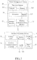
- a vehicle 1 is provided with a power management device 2 according to an embodiment of this disclosure.
- the vehicle 1 may be a motorcycle, a scooter, a car, an all-terrain vehicle (ATV), a utility vehicle (UV), or any transportation equipment.
- ATV all-terrain vehicle
- UV utility vehicle
- the vehicle 1 includes a vehicle body 10, and the power management device 2 is disposed in the vehicle body 10.
- the power management device 2 includes an electrical system 20, a processor 21, a wireless communication module 22 and a storage module 23.
- the electrical system 20 includes a power switch 201 (i.e., a main switch of the vehicle 1), and a battery 202 electrically connected to the power switch 201.
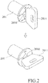
- the power switch 201 has a key hole 2010 that is paired with a key 2011, and is operable to switch between a conductive state (see the upper part of Figure 2 ) and a non-conductive state (see the lower part of Figure 2 ) .
- the user can insert the key 2011 into the key hole 2010, and turn the key 2011 clockwise to an "ON" position so that the power switch 201 is in the conductive state. To the contrary, the user can turn the key 2011 counterclockwise to an "OFF" position so that the power switch 201 is in the non-conductive state.
- the power switch 201 may be a press button, or a keyless main switch paired with a smart key, but is not limited thereto.
- the battery 202 of the electrical system 20 supplies electric power to the vehicle 1.
- the battery 202 does not supply electric power to most components of the vehicle 1 (e.g., a stereo system and headlights that are not shown in the Figures), except at least the processor 21, at least for a period of time.
- the processor 21 is electrically connected to the electrical system 20.
- the wireless communication module 22 is electrically connected to the processor 21, and is capable of establishing a wireless connection with a portable electronic device 3.
- the storage module 23 is electrically connected to the processor 21, and stores firmware causing the processor 21 to implement a power management method when executed by the processor 21.
- the wireless communication module 22 is a Bluetooth® device, and the storage module 23 may be a read-only memory, a flash memory or a solid state drive.
- the portable electronic device 3 may be a smart phone or a tablet, and includes a mobile processor 31, a storage unit 32, a wireless communication element 33, a display unit 34 and an input unit 35.
- the wireless communication element 33 is compatible with the wireless communication module 22 and is used to establish the wireless connection with the wireless communication module 22.
- the wireless communication element 33 is a Bluetooth® device.
- step S51 the processor 21 determines whether the power switch 201 is switched from the conductive state to the non-conductive state. It should be noted that the determination made in step S51 may be implemented by known approaches. For example, the processor 21 may detect any change in an electric current between the electrical system 20 and an engine (not shown in the Figures) of the vehicle 1. When it is determined that the power switch 201 is not switched from the conductive state to the non-conductive state, step S51 is repeated. Otherwise, the flow will proceed to step S52.
- the processor 21 controls the electrical system 20 to temporarily supply the wireless communication module 22 with electric power from the battery 202, so that the wireless communication module 22 is in a standby state and is capable of establishing or maintaining the wireless connection with the portable electronic device 3.
- the battery 202 of the electrical system 20 does not supply electric power to most components of the vehicle 1 (e.g., a stereo system and headlights that are not shown in the Figures), except the processor 21, which implements the power management method to selectively control supply of electric power to the wireless communication module 22, as will become apparent after the method has been fully described.
- the processor 21 controlling the supply of electric power to the wireless communication module 22, even when the user parks the vehicle 1 and switches the power switch 201 to the non-conductive state, for at least a period of time, the user can still operate the portable electronic device 3 to establish the wireless connection with the wireless communication module 22.
- the wireless communication module 22 may continuously detect a wireless signal transmitted by the portable electronic device 3 that is paired with the wireless communication module 22 in advance.
- the processor 21 may control, for example, turn-signal lights (not shown in the Figures) to emit a flashing light as an indication of a position of the vehicle 1 for the approaching user.
- the processor 21 further activates a timer 213 to start timing and controls the wireless communication module 22 to transmit a key-off signal to the portable electronic device 3.
- the portable electronic device 3 displays on the display unit 34 a timing interface showing a timing result of the timer 213 according to the key-off signal.
- the processor 21 activates the timer 213 to count down a predetermined duration, and the timing interface indicates countdown of the predetermined duration.
- the predetermined duration is a duration for which the wireless communication module 22 is to remain in the standby state .
- the user of the portable electronic device 3 can know the remaining time the wireless communication module 22 will be in the standby state from the timing interface shown on the display unit 34.
- the predetermined duration is forty-eight hours and can be modified by the user using an application software (APP) 321 stored in the storage unit 32 (e.g., a solid-state drive) of the portable electronic device 3 when the wireless connection is established.
- APP application software
- the display unit 34 and the input unit 35 may be integrated as a touch screen, and the user can modify the predetermined duration by operating the application software 321 on the touch screen.
- step S53 the processor 21 determines whether the timer 213 has counted down to zero. In other words, essentially, the processor 21 determines whether a period of electric power supply to the wireless communication module 22 after the power switch 201 is switched to the non-conductive state (i.e., an elapsed time after the timer 213 starts timing, also referred to as a supply duration) has reached the predetermined duration according to the timer 213.
- the flow goes to step S54 when it is determined that the timer 213 has counted down to zero (i.e., that the supply duration has reached the predetermined duration), and goes to step S55 when otherwise.
- step S54 the processor 21 controls the electrical system 20 to stop supplying electric power to the wireless communication module 22.
- the processor 21 may subsequently shut down supply of electric power from the battery 202 thereto. Accordingly, after step S54, the battery 202 outputs no electric power until the power switch 201 is switched to the conductive state, and the method is terminated.
- step S55 the processor 21 further determines whether the the power switch 201 is switched from the non-conductive state to the conductive state. When it is determined that the the power switch 201 is not switched from the non-conductive state to the conductive state, the flow will go back to step S53 and the wireless communication module 22 remains in the standby state; the flow will proceed to step S56 when otherwise.
- step S56 the processor 21 controls the timer 213 to stop timing the predetermined duration and resets the timer 213, and then, the method is terminated. It should be noted that, since the power switch 201 is switched from the non-conductive state to the conductive state as determined in step S55, the vehicle 1 is activated now, and the processor 21 will implement the power management method again by starting step S51.
- the power management device 2 allows the wireless communication module 22 to keep working for the predetermined duration upon the vehicle 1 being inactivated (i.e., the power switch 201 being switched from the conductive state to the non-conductive state) .
- the wireless communication module 22 can not only establish the wireless connection with the portable electronic device 3, but also perform specific functions (e.g., controlling the turn-signal lights to emit the flashing light as an indication upon detecting the wireless signal from the portable electronic device 3).
- the electrical power supply from the battery 202 to the wireless communication module 22 will be cut off, so that the battery 202 is prevented from depletion.
- the wireless communication module 22 can still function for the predetermined duration after the engine of the vehicle 1 is turned off and the battery 202 will not be depleted even if the engine is turned off for a long time. For example, when the user is going to take an airplane to go abroad for a week and parks the vehicle 1 at a parking lot of an airport, the wireless communication module 22 keeps working for, and only for, the predetermined duration (e.g., 48 hours) after the power switch 201 is turned to the non-conductive state, and then the battery 202 stops supplying electric power after the predetermined duration has elapsed. Therefore, when the user comes back to the parking lot and switches the power switch 201 to the conductive state, the battery 202 will still have enough electrical power to turn on the engine and to activate the vehicle 1.
- the predetermined duration e.g. 48 hours
- the wireless communication module 22 can transmit the key-off signal to make the portable electronic device 3 display the timing interface on the display unit 34 to show the remaining time before the predetermined duration ends. Accordingly, the user can know whether the wireless communication module 22 is still functional with the portable electronic device 3.
Landscapes
- Engineering & Computer Science (AREA)
- Mechanical Engineering (AREA)
- Human Computer Interaction (AREA)
- Computer Networks & Wireless Communication (AREA)
- Signal Processing (AREA)
- Charge And Discharge Circuits For Batteries Or The Like (AREA)
- Secondary Cells (AREA)
- Fittings On The Vehicle Exterior For Carrying Loads, And Devices For Holding Or Mounting Articles (AREA)
- Telephonic Communication Services (AREA)
Applications Claiming Priority (1)
| Application Number | Priority Date | Filing Date | Title |
|---|---|---|---|
| TW105133151A TWI616046B (zh) | 2016-10-14 | 2016-10-14 | 智慧型車輛電源管理方法及裝置 |
Publications (2)
| Publication Number | Publication Date |
|---|---|
| EP3309016A1 true EP3309016A1 (fr) | 2018-04-18 |
| EP3309016B1 EP3309016B1 (fr) | 2021-04-07 |
Family
ID=60190553
Family Applications (1)
| Application Number | Title | Priority Date | Filing Date |
|---|---|---|---|
| EP17195688.1A Active EP3309016B1 (fr) | 2016-10-14 | 2017-10-10 | Procédé et dispositif de gestion de puissance |
Country Status (6)
| Country | Link |
|---|---|
| US (1) | US10640064B2 (fr) |
| EP (1) | EP3309016B1 (fr) |
| JP (1) | JP2018062336A (fr) |
| ES (1) | ES2874591T3 (fr) |
| PH (1) | PH12017000286B1 (fr) |
| TW (1) | TWI616046B (fr) |
Citations (4)
| Publication number | Priority date | Publication date | Assignee | Title |
|---|---|---|---|---|
| EP1965565A2 (fr) * | 2006-04-13 | 2008-09-03 | Honda Motor Co., Ltd | Système de gestion de l'alimentation de véhicule à moteur |
| EP2769884A1 (fr) * | 2011-10-20 | 2014-08-27 | Honda Motor Co., Ltd. | Dispositif de commande de véhicule |
| WO2016051227A1 (fr) * | 2014-09-29 | 2016-04-07 | Pismo Labs Technology Limited | Procédés et systèmes destinés à la gestion d'une alimentation électrique au niveau d'un dispositif |
| US20160288744A1 (en) * | 2015-03-30 | 2016-10-06 | Parallel Wireless, Inc. | Power Management for Vehicle-Mounted Base Station |
Family Cites Families (16)
| Publication number | Priority date | Publication date | Assignee | Title |
|---|---|---|---|---|
| US8089323B2 (en) * | 2006-08-05 | 2012-01-03 | Min Ming Tarng | Green technology: green circuit and device designs of green chip |
| SE503254C2 (sv) * | 1994-07-04 | 1996-04-29 | Vattenfall Ab | Eldistributionsnät, förfarande och anordning för reglering av elektrisk ström från nätet |
| FR2776460A1 (fr) * | 1998-03-20 | 1999-09-24 | Philips Electronics Nv | Procede et dispositif d'economie d'energie, et equipement electronique embarque |
| WO2001086798A1 (fr) * | 2000-05-05 | 2001-11-15 | Advanced Materials Corporation | Systeme de commande moteur pour moteurs alimentes par batteries |
| US20040201365A1 (en) * | 2001-04-05 | 2004-10-14 | Electrovaya Inc. | Energy storage device for loads having variable power rates |
| US7610035B2 (en) * | 2002-12-31 | 2009-10-27 | Temic Automotive Of North America, Inc. | System and method for controlling the power in a wireless client device |
| JP4240016B2 (ja) * | 2004-08-24 | 2009-03-18 | 株式会社デンソー | 車両用受信装置 |
| US9170986B2 (en) * | 2009-11-06 | 2015-10-27 | City University Of Hong Kong | Power quality meter and method of waveform anaylsis and compression |
| DE102011008675A1 (de) * | 2011-01-15 | 2012-07-19 | Daimler Ag | Verfahren zum Aufladen einer Batterie eines Fahrzeuges |
| JP5312557B2 (ja) * | 2011-11-10 | 2013-10-09 | 三菱電機株式会社 | 電源管理装置、電源管理方法、および、電源管理システム |
| JP2014069592A (ja) * | 2012-09-27 | 2014-04-21 | Mitsubishi Motors Corp | 車載機器の遠隔操作システム |
| JP2014087036A (ja) * | 2012-10-26 | 2014-05-12 | Secom Co Ltd | 通信装置、センタ装置、通信システム、通信制御方法及び通信制御プログラム |
| TWI526815B (zh) * | 2014-09-10 | 2016-03-21 | 秦祖敬 | 智慧電源監控系統及其實施方法 |
| TWM514152U (zh) * | 2015-07-03 | 2015-12-11 | Jing Feng Technology Co Ltd | 車輛用之備用電源裝置 |
| US10543754B2 (en) * | 2016-07-05 | 2020-01-28 | Hyundai Motor Company | Charging control apparatus and method for electric vehicle and billing system using the same |
| US10230198B2 (en) * | 2016-09-29 | 2019-03-12 | Schneider Electric USA, Inc. | EVSE energy management system retrofit coupling |
-
2016
- 2016-10-14 TW TW105133151A patent/TWI616046B/zh active
-
2017
- 2017-10-06 PH PH12017000286A patent/PH12017000286B1/en unknown
- 2017-10-06 US US15/726,914 patent/US10640064B2/en active Active
- 2017-10-10 EP EP17195688.1A patent/EP3309016B1/fr active Active
- 2017-10-10 ES ES17195688T patent/ES2874591T3/es active Active
- 2017-10-11 JP JP2017197438A patent/JP2018062336A/ja active Pending
Patent Citations (4)
| Publication number | Priority date | Publication date | Assignee | Title |
|---|---|---|---|---|
| EP1965565A2 (fr) * | 2006-04-13 | 2008-09-03 | Honda Motor Co., Ltd | Système de gestion de l'alimentation de véhicule à moteur |
| EP2769884A1 (fr) * | 2011-10-20 | 2014-08-27 | Honda Motor Co., Ltd. | Dispositif de commande de véhicule |
| WO2016051227A1 (fr) * | 2014-09-29 | 2016-04-07 | Pismo Labs Technology Limited | Procédés et systèmes destinés à la gestion d'une alimentation électrique au niveau d'un dispositif |
| US20160288744A1 (en) * | 2015-03-30 | 2016-10-06 | Parallel Wireless, Inc. | Power Management for Vehicle-Mounted Base Station |
Also Published As
| Publication number | Publication date |
|---|---|
| ES2874591T3 (es) | 2021-11-05 |
| TW201815017A (zh) | 2018-04-16 |
| JP2018062336A (ja) | 2018-04-19 |
| PH12017000286A1 (en) | 2019-01-28 |
| TWI616046B (zh) | 2018-02-21 |
| PH12017000286B1 (en) | 2019-01-28 |
| EP3309016B1 (fr) | 2021-04-07 |
| US10640064B2 (en) | 2020-05-05 |
| US20180105127A1 (en) | 2018-04-19 |
Similar Documents
| Publication | Publication Date | Title |
|---|---|---|
| US20200186757A1 (en) | Vehicle camera peripheral | |
| US20180108186A1 (en) | Method for updating firmware of a vehicle and a vehicle system | |
| RU2017105458A (ru) | Управление световым индикатором зарядки | |
| US10123401B2 (en) | Method and indicating system for a vehicle | |
| JP2001223773A (ja) | 移動体通信端末機のディスプレイ装置の動作状態に依存した制御に基づくエネルギー節減回路 | |
| JP6098216B2 (ja) | タイマ備忘装置 | |
| WO2014177064A1 (fr) | Appareil doté d'une interface | |
| US10640064B2 (en) | Power management method and device | |
| KR20190062986A (ko) | 스위치 점멸 장치 | |
| CN104037889A (zh) | 新型防滑带蓝牙及手电功能双线汽车应急点火电源 | |
| US10279689B2 (en) | Battery rescue activating reset device | |
| CN103762668A (zh) | 一种新型带充电及蓝牙功能便携式汽车应急点火电源 | |
| CN104065131A (zh) | 新型防滑带mp3及充电功能双线汽车应急点火电源 | |
| CN104608740B (zh) | 一种无钥匙启动装置 | |
| JP6349766B2 (ja) | 車載装置、及び車両用通信システム | |
| JP2006026147A (ja) | 電動ミシン | |
| KR100648333B1 (ko) | 휴대폰의 충전방법 | |
| CN104300627A (zh) | 新型防滑带充电及mp3功能双线汽车应急点火电源 | |
| JP2006129353A (ja) | 近距離無線伝送装置 | |
| CN104037908A (zh) | 新型带蓝牙及充电功能双线汽车应急点火电源 | |
| CN103779944A (zh) | 新型防滑带充电及蓝牙功能便携式汽车应急点火电源 | |
| CN104283280A (zh) | 新型防滑带充电及蓝牙功能双线汽车应急点火电源 | |
| KR20240053103A (ko) | 운전자 편의 기능 설정을 위한 장치 및 방법 | |
| CN103762656A (zh) | 一种新型带充电及mp3功能便携式汽车应急点火电源 | |
| CN104052126A (zh) | 一种新型带充电及蓝牙功能双线汽车应急点火电源 |
Legal Events
| Date | Code | Title | Description |
|---|---|---|---|
| PUAI | Public reference made under article 153(3) epc to a published international application that has entered the european phase |
Free format text: ORIGINAL CODE: 0009012 |
|
| STAA | Information on the status of an ep patent application or granted ep patent |
Free format text: STATUS: THE APPLICATION HAS BEEN PUBLISHED |
|
| AK | Designated contracting states |
Kind code of ref document: A1 Designated state(s): AL AT BE BG CH CY CZ DE DK EE ES FI FR GB GR HR HU IE IS IT LI LT LU LV MC MK MT NL NO PL PT RO RS SE SI SK SM TR |
|
| AX | Request for extension of the european patent |
Extension state: BA ME |
|
| STAA | Information on the status of an ep patent application or granted ep patent |
Free format text: STATUS: REQUEST FOR EXAMINATION WAS MADE |
|
| 17P | Request for examination filed |
Effective date: 20181012 |
|
| RBV | Designated contracting states (corrected) |
Designated state(s): AL AT BE BG CH CY CZ DE DK EE ES FI FR GB GR HR HU IE IS IT LI LT LU LV MC MK MT NL NO PL PT RO RS SE SI SK SM TR |
|
| GRAP | Despatch of communication of intention to grant a patent |
Free format text: ORIGINAL CODE: EPIDOSNIGR1 |
|
| STAA | Information on the status of an ep patent application or granted ep patent |
Free format text: STATUS: GRANT OF PATENT IS INTENDED |
|
| INTG | Intention to grant announced |
Effective date: 20201021 |
|
| RIN1 | Information on inventor provided before grant (corrected) |
Inventor name: TSAI, YI-YANG Inventor name: CHEN, LI-HUI Inventor name: LIU, TE-CHUAN Inventor name: HSU, CHI-HUI Inventor name: YEH, NAI-KUN Inventor name: SU, PING-CHEN Inventor name: LIN, CHEN-SHENG |
|
| GRAS | Grant fee paid |
Free format text: ORIGINAL CODE: EPIDOSNIGR3 |
|
| GRAA | (expected) grant |
Free format text: ORIGINAL CODE: 0009210 |
|
| STAA | Information on the status of an ep patent application or granted ep patent |
Free format text: STATUS: THE PATENT HAS BEEN GRANTED |
|
| AK | Designated contracting states |
Kind code of ref document: B1 Designated state(s): AL AT BE BG CH CY CZ DE DK EE ES FI FR GB GR HR HU IE IS IT LI LT LU LV MC MK MT NL NO PL PT RO RS SE SI SK SM TR |
|
| REG | Reference to a national code |
Ref country code: GB Ref legal event code: FG4D |
|
| REG | Reference to a national code |
Ref country code: AT Ref legal event code: REF Ref document number: 1379296 Country of ref document: AT Kind code of ref document: T Effective date: 20210415 Ref country code: CH Ref legal event code: EP |
|
| REG | Reference to a national code |
Ref country code: DE Ref legal event code: R096 Ref document number: 602017036068 Country of ref document: DE |
|
| REG | Reference to a national code |
Ref country code: IE Ref legal event code: FG4D |
|
| REG | Reference to a national code |
Ref country code: LT Ref legal event code: MG9D |
|
| REG | Reference to a national code |
Ref country code: NL Ref legal event code: MP Effective date: 20210407 Ref country code: AT Ref legal event code: MK05 Ref document number: 1379296 Country of ref document: AT Kind code of ref document: T Effective date: 20210407 |
|
| PG25 | Lapsed in a contracting state [announced via postgrant information from national office to epo] |
Ref country code: NL Free format text: LAPSE BECAUSE OF FAILURE TO SUBMIT A TRANSLATION OF THE DESCRIPTION OR TO PAY THE FEE WITHIN THE PRESCRIBED TIME-LIMIT Effective date: 20210407 Ref country code: HR Free format text: LAPSE BECAUSE OF FAILURE TO SUBMIT A TRANSLATION OF THE DESCRIPTION OR TO PAY THE FEE WITHIN THE PRESCRIBED TIME-LIMIT Effective date: 20210407 Ref country code: AT Free format text: LAPSE BECAUSE OF FAILURE TO SUBMIT A TRANSLATION OF THE DESCRIPTION OR TO PAY THE FEE WITHIN THE PRESCRIBED TIME-LIMIT Effective date: 20210407 Ref country code: BG Free format text: LAPSE BECAUSE OF FAILURE TO SUBMIT A TRANSLATION OF THE DESCRIPTION OR TO PAY THE FEE WITHIN THE PRESCRIBED TIME-LIMIT Effective date: 20210707 Ref country code: FI Free format text: LAPSE BECAUSE OF FAILURE TO SUBMIT A TRANSLATION OF THE DESCRIPTION OR TO PAY THE FEE WITHIN THE PRESCRIBED TIME-LIMIT Effective date: 20210407 Ref country code: LT Free format text: LAPSE BECAUSE OF FAILURE TO SUBMIT A TRANSLATION OF THE DESCRIPTION OR TO PAY THE FEE WITHIN THE PRESCRIBED TIME-LIMIT Effective date: 20210407 |
|
| REG | Reference to a national code |
Ref country code: ES Ref legal event code: FG2A Ref document number: 2874591 Country of ref document: ES Kind code of ref document: T3 Effective date: 20211105 |
|
| PG25 | Lapsed in a contracting state [announced via postgrant information from national office to epo] |
Ref country code: GR Free format text: LAPSE BECAUSE OF FAILURE TO SUBMIT A TRANSLATION OF THE DESCRIPTION OR TO PAY THE FEE WITHIN THE PRESCRIBED TIME-LIMIT Effective date: 20210708 Ref country code: IS Free format text: LAPSE BECAUSE OF FAILURE TO SUBMIT A TRANSLATION OF THE DESCRIPTION OR TO PAY THE FEE WITHIN THE PRESCRIBED TIME-LIMIT Effective date: 20210807 Ref country code: LV Free format text: LAPSE BECAUSE OF FAILURE TO SUBMIT A TRANSLATION OF THE DESCRIPTION OR TO PAY THE FEE WITHIN THE PRESCRIBED TIME-LIMIT Effective date: 20210407 Ref country code: NO Free format text: LAPSE BECAUSE OF FAILURE TO SUBMIT A TRANSLATION OF THE DESCRIPTION OR TO PAY THE FEE WITHIN THE PRESCRIBED TIME-LIMIT Effective date: 20210707 Ref country code: PL Free format text: LAPSE BECAUSE OF FAILURE TO SUBMIT A TRANSLATION OF THE DESCRIPTION OR TO PAY THE FEE WITHIN THE PRESCRIBED TIME-LIMIT Effective date: 20210407 Ref country code: PT Free format text: LAPSE BECAUSE OF FAILURE TO SUBMIT A TRANSLATION OF THE DESCRIPTION OR TO PAY THE FEE WITHIN THE PRESCRIBED TIME-LIMIT Effective date: 20210809 Ref country code: RS Free format text: LAPSE BECAUSE OF FAILURE TO SUBMIT A TRANSLATION OF THE DESCRIPTION OR TO PAY THE FEE WITHIN THE PRESCRIBED TIME-LIMIT Effective date: 20210407 Ref country code: SE Free format text: LAPSE BECAUSE OF FAILURE TO SUBMIT A TRANSLATION OF THE DESCRIPTION OR TO PAY THE FEE WITHIN THE PRESCRIBED TIME-LIMIT Effective date: 20210407 |
|
| REG | Reference to a national code |
Ref country code: DE Ref legal event code: R097 Ref document number: 602017036068 Country of ref document: DE |
|
| PG25 | Lapsed in a contracting state [announced via postgrant information from national office to epo] |
Ref country code: SM Free format text: LAPSE BECAUSE OF FAILURE TO SUBMIT A TRANSLATION OF THE DESCRIPTION OR TO PAY THE FEE WITHIN THE PRESCRIBED TIME-LIMIT Effective date: 20210407 Ref country code: SK Free format text: LAPSE BECAUSE OF FAILURE TO SUBMIT A TRANSLATION OF THE DESCRIPTION OR TO PAY THE FEE WITHIN THE PRESCRIBED TIME-LIMIT Effective date: 20210407 Ref country code: CZ Free format text: LAPSE BECAUSE OF FAILURE TO SUBMIT A TRANSLATION OF THE DESCRIPTION OR TO PAY THE FEE WITHIN THE PRESCRIBED TIME-LIMIT Effective date: 20210407 Ref country code: EE Free format text: LAPSE BECAUSE OF FAILURE TO SUBMIT A TRANSLATION OF THE DESCRIPTION OR TO PAY THE FEE WITHIN THE PRESCRIBED TIME-LIMIT Effective date: 20210407 Ref country code: DK Free format text: LAPSE BECAUSE OF FAILURE TO SUBMIT A TRANSLATION OF THE DESCRIPTION OR TO PAY THE FEE WITHIN THE PRESCRIBED TIME-LIMIT Effective date: 20210407 Ref country code: RO Free format text: LAPSE BECAUSE OF FAILURE TO SUBMIT A TRANSLATION OF THE DESCRIPTION OR TO PAY THE FEE WITHIN THE PRESCRIBED TIME-LIMIT Effective date: 20210407 |
|
| PLBE | No opposition filed within time limit |
Free format text: ORIGINAL CODE: 0009261 |
|
| STAA | Information on the status of an ep patent application or granted ep patent |
Free format text: STATUS: NO OPPOSITION FILED WITHIN TIME LIMIT |
|
| 26N | No opposition filed |
Effective date: 20220110 |
|
| REG | Reference to a national code |
Ref country code: DE Ref legal event code: R119 Ref document number: 602017036068 Country of ref document: DE |
|
| REG | Reference to a national code |
Ref country code: CH Ref legal event code: PL |
|
| PG25 | Lapsed in a contracting state [announced via postgrant information from national office to epo] |
Ref country code: IS Free format text: LAPSE BECAUSE OF FAILURE TO SUBMIT A TRANSLATION OF THE DESCRIPTION OR TO PAY THE FEE WITHIN THE PRESCRIBED TIME-LIMIT Effective date: 20210807 Ref country code: AL Free format text: LAPSE BECAUSE OF FAILURE TO SUBMIT A TRANSLATION OF THE DESCRIPTION OR TO PAY THE FEE WITHIN THE PRESCRIBED TIME-LIMIT Effective date: 20210407 |
|
| REG | Reference to a national code |
Ref country code: BE Ref legal event code: MM Effective date: 20211031 |
|
| GBPC | Gb: european patent ceased through non-payment of renewal fee |
Effective date: 20211010 |
|
| PG25 | Lapsed in a contracting state [announced via postgrant information from national office to epo] |
Ref country code: MC Free format text: LAPSE BECAUSE OF FAILURE TO SUBMIT A TRANSLATION OF THE DESCRIPTION OR TO PAY THE FEE WITHIN THE PRESCRIBED TIME-LIMIT Effective date: 20210407 |
|
| PG25 | Lapsed in a contracting state [announced via postgrant information from national office to epo] |
Ref country code: LU Free format text: LAPSE BECAUSE OF NON-PAYMENT OF DUE FEES Effective date: 20211010 Ref country code: GB Free format text: LAPSE BECAUSE OF NON-PAYMENT OF DUE FEES Effective date: 20211010 Ref country code: DE Free format text: LAPSE BECAUSE OF NON-PAYMENT OF DUE FEES Effective date: 20220503 Ref country code: BE Free format text: LAPSE BECAUSE OF NON-PAYMENT OF DUE FEES Effective date: 20211031 |
|
| PG25 | Lapsed in a contracting state [announced via postgrant information from national office to epo] |
Ref country code: LI Free format text: LAPSE BECAUSE OF NON-PAYMENT OF DUE FEES Effective date: 20211031 Ref country code: CH Free format text: LAPSE BECAUSE OF NON-PAYMENT OF DUE FEES Effective date: 20211031 |
|
| PG25 | Lapsed in a contracting state [announced via postgrant information from national office to epo] |
Ref country code: FR Free format text: LAPSE BECAUSE OF NON-PAYMENT OF DUE FEES Effective date: 20211031 |
|
| PG25 | Lapsed in a contracting state [announced via postgrant information from national office to epo] |
Ref country code: IE Free format text: LAPSE BECAUSE OF NON-PAYMENT OF DUE FEES Effective date: 20211010 |
|
| REG | Reference to a national code |
Ref country code: ES Ref legal event code: FD2A Effective date: 20221125 |
|
| PG25 | Lapsed in a contracting state [announced via postgrant information from national office to epo] |
Ref country code: ES Free format text: LAPSE BECAUSE OF NON-PAYMENT OF DUE FEES Effective date: 20211011 |
|
| PG25 | Lapsed in a contracting state [announced via postgrant information from national office to epo] |
Ref country code: HU Free format text: LAPSE BECAUSE OF FAILURE TO SUBMIT A TRANSLATION OF THE DESCRIPTION OR TO PAY THE FEE WITHIN THE PRESCRIBED TIME-LIMIT; INVALID AB INITIO Effective date: 20171010 |
|
| PG25 | Lapsed in a contracting state [announced via postgrant information from national office to epo] |
Ref country code: CY Free format text: LAPSE BECAUSE OF FAILURE TO SUBMIT A TRANSLATION OF THE DESCRIPTION OR TO PAY THE FEE WITHIN THE PRESCRIBED TIME-LIMIT Effective date: 20210407 |
|
| PGFP | Annual fee paid to national office [announced via postgrant information from national office to epo] |
Ref country code: IT Payment date: 20231018 Year of fee payment: 7 |
|
| PG25 | Lapsed in a contracting state [announced via postgrant information from national office to epo] |
Ref country code: MK Free format text: LAPSE BECAUSE OF FAILURE TO SUBMIT A TRANSLATION OF THE DESCRIPTION OR TO PAY THE FEE WITHIN THE PRESCRIBED TIME-LIMIT Effective date: 20210407 |