EP3308004B1 - Système et procédé pour le démarrage d'une installation de production d'énergie - Google Patents
Système et procédé pour le démarrage d'une installation de production d'énergie Download PDFInfo
- Publication number
- EP3308004B1 EP3308004B1 EP16738244.9A EP16738244A EP3308004B1 EP 3308004 B1 EP3308004 B1 EP 3308004B1 EP 16738244 A EP16738244 A EP 16738244A EP 3308004 B1 EP3308004 B1 EP 3308004B1
- Authority
- EP
- European Patent Office
- Prior art keywords
- oxidant
- stream
- compressor
- turbine
- recycle
- Prior art date
- Legal status (The legal status is an assumption and is not a legal conclusion. Google has not performed a legal analysis and makes no representation as to the accuracy of the status listed.)
- Active
Links
- 238000004519 manufacturing process Methods 0.000 title claims description 37
- 238000000034 method Methods 0.000 title claims description 25
- 239000007800 oxidant agent Substances 0.000 claims description 76
- 230000001590 oxidative effect Effects 0.000 claims description 76
- 238000002485 combustion reaction Methods 0.000 claims description 33
- 210000004907 gland Anatomy 0.000 claims description 23
- 239000000446 fuel Substances 0.000 claims description 17
- XLYOFNOQVPJJNP-UHFFFAOYSA-N water Substances O XLYOFNOQVPJJNP-UHFFFAOYSA-N 0.000 claims description 11
- 239000000203 mixture Substances 0.000 claims description 7
- 238000001816 cooling Methods 0.000 claims description 2
- CURLTUGMZLYLDI-UHFFFAOYSA-N Carbon dioxide Chemical compound O=C=O CURLTUGMZLYLDI-UHFFFAOYSA-N 0.000 description 88
- 229910002092 carbon dioxide Inorganic materials 0.000 description 82
- 239000007789 gas Substances 0.000 description 16
- QVGXLLKOCUKJST-UHFFFAOYSA-N atomic oxygen Chemical compound [O] QVGXLLKOCUKJST-UHFFFAOYSA-N 0.000 description 14
- 229910052760 oxygen Inorganic materials 0.000 description 14
- 239000001301 oxygen Substances 0.000 description 14
- 239000012530 fluid Substances 0.000 description 9
- VNWKTOKETHGBQD-UHFFFAOYSA-N methane Chemical compound C VNWKTOKETHGBQD-UHFFFAOYSA-N 0.000 description 7
- 239000001569 carbon dioxide Substances 0.000 description 6
- 239000002737 fuel gas Substances 0.000 description 5
- 238000010438 heat treatment Methods 0.000 description 5
- 239000002803 fossil fuel Substances 0.000 description 4
- 230000003647 oxidation Effects 0.000 description 4
- 238000007254 oxidation reaction Methods 0.000 description 4
- 239000007787 solid Substances 0.000 description 4
- MYMOFIZGZYHOMD-UHFFFAOYSA-N Dioxygen Chemical compound O=O MYMOFIZGZYHOMD-UHFFFAOYSA-N 0.000 description 3
- 230000008901 benefit Effects 0.000 description 3
- 239000003245 coal Substances 0.000 description 3
- 230000006835 compression Effects 0.000 description 3
- 238000007906 compression Methods 0.000 description 3
- 239000000356 contaminant Substances 0.000 description 3
- 239000012535 impurity Substances 0.000 description 3
- 239000003345 natural gas Substances 0.000 description 3
- 230000005068 transpiration Effects 0.000 description 3
- 239000000654 additive Substances 0.000 description 2
- 230000000996 additive effect Effects 0.000 description 2
- 230000001276 controlling effect Effects 0.000 description 2
- 238000010586 diagram Methods 0.000 description 2
- 239000003077 lignite Substances 0.000 description 2
- 239000007788 liquid Substances 0.000 description 2
- 238000012986 modification Methods 0.000 description 2
- 230000004048 modification Effects 0.000 description 2
- 239000002006 petroleum coke Substances 0.000 description 2
- 238000010791 quenching Methods 0.000 description 2
- 238000000926 separation method Methods 0.000 description 2
- 238000011144 upstream manufacturing Methods 0.000 description 2
- 239000002028 Biomass Substances 0.000 description 1
- 239000010426 asphalt Substances 0.000 description 1
- 230000009286 beneficial effect Effects 0.000 description 1
- 238000006243 chemical reaction Methods 0.000 description 1
- 239000000470 constituent Substances 0.000 description 1
- 230000001627 detrimental effect Effects 0.000 description 1
- 229910001882 dioxygen Inorganic materials 0.000 description 1
- 230000005611 electricity Effects 0.000 description 1
- 238000010348 incorporation Methods 0.000 description 1
- 239000002245 particle Substances 0.000 description 1
- 238000010248 power generation Methods 0.000 description 1
- 230000003134 recirculating effect Effects 0.000 description 1
- 230000001105 regulatory effect Effects 0.000 description 1
- 230000009919 sequestration Effects 0.000 description 1
- 239000004449 solid propellant Substances 0.000 description 1
- 150000003464 sulfur compounds Chemical class 0.000 description 1
- 230000007704 transition Effects 0.000 description 1
Images
Classifications
-
- F—MECHANICAL ENGINEERING; LIGHTING; HEATING; WEAPONS; BLASTING
- F01—MACHINES OR ENGINES IN GENERAL; ENGINE PLANTS IN GENERAL; STEAM ENGINES
- F01K—STEAM ENGINE PLANTS; STEAM ACCUMULATORS; ENGINE PLANTS NOT OTHERWISE PROVIDED FOR; ENGINES USING SPECIAL WORKING FLUIDS OR CYCLES
- F01K25/00—Plants or engines characterised by use of special working fluids, not otherwise provided for; Plants operating in closed cycles and not otherwise provided for
- F01K25/08—Plants or engines characterised by use of special working fluids, not otherwise provided for; Plants operating in closed cycles and not otherwise provided for using special vapours
- F01K25/10—Plants or engines characterised by use of special working fluids, not otherwise provided for; Plants operating in closed cycles and not otherwise provided for using special vapours the vapours being cold, e.g. ammonia, carbon dioxide, ether
- F01K25/103—Carbon dioxide
-
- F—MECHANICAL ENGINEERING; LIGHTING; HEATING; WEAPONS; BLASTING
- F02—COMBUSTION ENGINES; HOT-GAS OR COMBUSTION-PRODUCT ENGINE PLANTS
- F02C—GAS-TURBINE PLANTS; AIR INTAKES FOR JET-PROPULSION PLANTS; CONTROLLING FUEL SUPPLY IN AIR-BREATHING JET-PROPULSION PLANTS
- F02C3/00—Gas-turbine plants characterised by the use of combustion products as the working fluid
- F02C3/34—Gas-turbine plants characterised by the use of combustion products as the working fluid with recycling of part of the working fluid, i.e. semi-closed cycles with combustion products in the closed part of the cycle
-
- F—MECHANICAL ENGINEERING; LIGHTING; HEATING; WEAPONS; BLASTING
- F01—MACHINES OR ENGINES IN GENERAL; ENGINE PLANTS IN GENERAL; STEAM ENGINES
- F01K—STEAM ENGINE PLANTS; STEAM ACCUMULATORS; ENGINE PLANTS NOT OTHERWISE PROVIDED FOR; ENGINES USING SPECIAL WORKING FLUIDS OR CYCLES
- F01K13/00—General layout or general methods of operation of complete plants
- F01K13/02—Controlling, e.g. stopping or starting
-
- F—MECHANICAL ENGINEERING; LIGHTING; HEATING; WEAPONS; BLASTING
- F02—COMBUSTION ENGINES; HOT-GAS OR COMBUSTION-PRODUCT ENGINE PLANTS
- F02C—GAS-TURBINE PLANTS; AIR INTAKES FOR JET-PROPULSION PLANTS; CONTROLLING FUEL SUPPLY IN AIR-BREATHING JET-PROPULSION PLANTS
- F02C1/00—Gas-turbine plants characterised by the use of hot gases or unheated pressurised gases, as the working fluid
- F02C1/04—Gas-turbine plants characterised by the use of hot gases or unheated pressurised gases, as the working fluid the working fluid being heated indirectly
- F02C1/08—Semi-closed cycles
-
- F—MECHANICAL ENGINEERING; LIGHTING; HEATING; WEAPONS; BLASTING
- F02—COMBUSTION ENGINES; HOT-GAS OR COMBUSTION-PRODUCT ENGINE PLANTS
- F02C—GAS-TURBINE PLANTS; AIR INTAKES FOR JET-PROPULSION PLANTS; CONTROLLING FUEL SUPPLY IN AIR-BREATHING JET-PROPULSION PLANTS
- F02C7/00—Features, components parts, details or accessories, not provided for in, or of interest apart form groups F02C1/00 - F02C6/00; Air intakes for jet-propulsion plants
- F02C7/08—Heating air supply before combustion, e.g. by exhaust gases
-
- F—MECHANICAL ENGINEERING; LIGHTING; HEATING; WEAPONS; BLASTING
- F23—COMBUSTION APPARATUS; COMBUSTION PROCESSES
- F23L—SUPPLYING AIR OR NON-COMBUSTIBLE LIQUIDS OR GASES TO COMBUSTION APPARATUS IN GENERAL ; VALVES OR DAMPERS SPECIALLY ADAPTED FOR CONTROLLING AIR SUPPLY OR DRAUGHT IN COMBUSTION APPARATUS; INDUCING DRAUGHT IN COMBUSTION APPARATUS; TOPS FOR CHIMNEYS OR VENTILATING SHAFTS; TERMINALS FOR FLUES
- F23L7/00—Supplying non-combustible liquids or gases, other than air, to the fire, e.g. oxygen, steam
- F23L7/007—Supplying oxygen or oxygen-enriched air
-
- F—MECHANICAL ENGINEERING; LIGHTING; HEATING; WEAPONS; BLASTING
- F05—INDEXING SCHEMES RELATING TO ENGINES OR PUMPS IN VARIOUS SUBCLASSES OF CLASSES F01-F04
- F05D—INDEXING SCHEME FOR ASPECTS RELATING TO NON-POSITIVE-DISPLACEMENT MACHINES OR ENGINES, GAS-TURBINES OR JET-PROPULSION PLANTS
- F05D2210/00—Working fluids
- F05D2210/10—Kind or type
- F05D2210/12—Kind or type gaseous, i.e. compressible
-
- F—MECHANICAL ENGINEERING; LIGHTING; HEATING; WEAPONS; BLASTING
- F05—INDEXING SCHEMES RELATING TO ENGINES OR PUMPS IN VARIOUS SUBCLASSES OF CLASSES F01-F04
- F05D—INDEXING SCHEME FOR ASPECTS RELATING TO NON-POSITIVE-DISPLACEMENT MACHINES OR ENGINES, GAS-TURBINES OR JET-PROPULSION PLANTS
- F05D2220/00—Application
- F05D2220/70—Application in combination with
- F05D2220/75—Application in combination with equipment using fuel having a low calorific value, e.g. low BTU fuel, waste end, syngas, biomass fuel or flare gas
-
- F—MECHANICAL ENGINEERING; LIGHTING; HEATING; WEAPONS; BLASTING
- F05—INDEXING SCHEMES RELATING TO ENGINES OR PUMPS IN VARIOUS SUBCLASSES OF CLASSES F01-F04
- F05D—INDEXING SCHEME FOR ASPECTS RELATING TO NON-POSITIVE-DISPLACEMENT MACHINES OR ENGINES, GAS-TURBINES OR JET-PROPULSION PLANTS
- F05D2260/00—Function
- F05D2260/60—Fluid transfer
- F05D2260/606—Bypassing the fluid
-
- F—MECHANICAL ENGINEERING; LIGHTING; HEATING; WEAPONS; BLASTING
- F05—INDEXING SCHEMES RELATING TO ENGINES OR PUMPS IN VARIOUS SUBCLASSES OF CLASSES F01-F04
- F05D—INDEXING SCHEME FOR ASPECTS RELATING TO NON-POSITIVE-DISPLACEMENT MACHINES OR ENGINES, GAS-TURBINES OR JET-PROPULSION PLANTS
- F05D2260/00—Function
- F05D2260/85—Starting
Definitions
- the presently disclosed subject matter relates to power production plants. Particularly, system configurations and methods are provided for startup of a power product plant.
- US 2014/000271 discloses a system for controlling the oxidant feed in low emission turbine systems to maintain stoichiometric or a substantially stoichiometric combustion conditions. Such control is achieved by diverting a portion of the recirculating exhaust gas and combining it with the oxidant feed to maintain a constant oxygen level in the combined oxidant-exhaust stream fed through the combustion chamber.
- US 4,434,613 discloses a combined cycle system to produce one or more chemically useful products, said cycle system employing a gas turbine. Selected exhaust gases are fed back into the gas turbine compressor so as to establish a stable mixture of working fluid constituents to for the gas turbine.
- US 5,724,805 discloses a power plant including an air separation unit arranged to separate oxygen from air and produce a stream of substantially pure liquid oxygen.
- a gas turbine is arranged to combust a fuel in the presence of substantially pure oxygen gas and carbon dioxide gas, and to produce an exhaust gas comprising water and carbon dioxide.
- a carbon dioxide removal unit is provided to recover carbon dioxide gas from the exhaust gas, recycle a portion of the recovered carbon dioxide gas for passage through the gas turbine, and liquefy the remainder of the recovered carbon dioxide gas for removal from the plant.
- US 2013/0269356 A1 discloses a S-EGR process that yields an exhaust stream that includes a relatively high concentration of a desirable gas and is also substantially oxygen-free.
- US 2013/0269311 A1 discloses a power plant configured to include a recirculation loop about which a working fluid is recirculated, the recirculation loop comprising a plurality of components configured to accept an outflow of working fluid from a neighboring upstream component and provide an inflow of working fluid to a neighboring downstream component.
- the present disclosure provides configurations that may be applied to a power production plant so that startup of the plant may proceed under a broader set of conditions that may otherwise be possible.
- the present disclosure enables startup of a combustion cycle power plant with combustor ignition below a turbine threshold speed that would otherwise be possible.
- the present disclosure relates to startup of power plants implementing a combustion cycle wherein CO 2 is utilized as a working fluid and wherein CO 2 formed in combustion may be captured.
- Examples of systems and methods for power production under such conditions are provided in U.S. Patent Nos. 8,596,075 to Allam et al., 8,776,532 to Allam et al. , 8,869,889 to Palmer et al. , 8,959,887 to Allam et al. , and 8,986,002 to Palmer et al. , as well as U.S. Patent Publication Nos. 2012/0067056 to Palmer et al. , 2012/0237881 to Allam et al. , 2013/0104525 to Allam et al ., and 2013/0118145 to Palmer et al.
- power production can be achieved utilizing a closed cycle or partially closed cycle system in which CO 2 is utilized as the working fluid.
- a fossil fuel or a fuel derived from a fossil fuel e.g., syngas derived from coal or other solid carbonaceous fuel
- an oxidant e.g., oxygen
- the oxygen may be mixed with CO 2 .
- the molar concentration of O 2 in the combined O 2 /CO 2 stream can be about 10% to about 50%, about 15% to about 40%, or about 20% to about 30%.
- Solid fossil fuels such as coal, lignite, or petroleum coke, that contain non-combustible ash may be converted to a gaseous fuel by partial oxidation in a single stage or multi-stage system.
- Such system may comprise a partial oxidation reactor.
- such system may comprise a partial oxidation reactor and an ash and volatile inorganic component removal system.
- Such systems further comprise combustion of the fuel gas with oxygen in the combustor of the power production system.
- a preheated recycle CO 2 stream is mixed in the combustor with the combustion products in the formed fuel gas.
- Any combustor adapted for operation under conditions otherwise described herein may be used, and the recycle CO 2 stream may be introduced to the combustor by any means to be further heated by the combustion and, if desired, to quench and thereby control the temperature of the exit stream.
- one or both of a POX reactor and the combustor may utilize, for purposes of example only, a transpiration cooled wall surrounding the reaction or combustion space, and the preheated recycle CO 2 stream may pass through the wall to both cool the wall and to quench and thereby control the temperature of the exit stream.
- the transpiration flow promotes good mixing between the recycle CO 2 and the hot combusted fuel gas streams.
- combustors may also be used, and the present disclosure is not limited to the use of transpiration cooled combustors.
- the combined combustion products and preheated recycle CO 2 leaving the combustor are at the temperature required for the inlet to a power-producing turbine.
- the hot turbine exhaust can be cooled in an economizing heat exchanger, which in turn preheats the high pressure CO 2 recycle stream.
- the power production systems and methods may be operated under a combined set of conditions that may be characterized as the "normal” or “standard” operating parameters.
- Each condition e.g., combustion temperature, turbine speed, compression ratios, etc.
- Each condition e.g., combustion temperature, turbine speed, compression ratios, etc.
- the "normal” or “standard” operating parameters may be defined in relation to operation of the power production system or method in its power producing state.
- a power production plant cannot go from idle conditions to full operational mode instantaneously. Rather, the components of the power production plant must be brought up to normal operating parameters according to a particular algorithm. For example, in a power production system wherein a turbine and a compressor are provided on a common shaft, compressor output is limited by turbine speed, and combustion may not begin until the compressor is providing sufficient flow of the CO 2 recycle stream to appropriately mediate combustion temperature. Accordingly, combustor ignition may not be possible until the turbine reaches a certain threshold speed.
- the shaft-driven compressor may not be capable of generating the required flow volume and flow pressure below a shaft speed that is about 85% of the final shaft speed ⁇ i.e., the shaft speed when the turbine is operating at its normal power production parameter. According to the present disclosure, however, systems and methods are provided wherein combustor ignition is possible below the turbine threshold value.
- the present disclosure thus provides a power production system as defined in claim 1.
- a power production system as defined in claim 1.
- Such system comprises: a combustor; a turbine including a gland seal and an air input; a first compressor, which is a shaft-driven compressor on a common shaft with the turbine; an oxidant compressor, which may be a motor-driven compressor; an exhaust flow line configured for passage of a turbine exhaust stream from the turbine to the first compressor; a recycle flow line configured for passage of a CO 2 recycle stream from the first compressor to the combustor; an oxidant flow line configured for passage of an oxidant stream from the oxidant compressor to the turbine; a bypass line configured for controllable passage of at least a portion of the oxidant stream from the oxidant flow lines to the recycle flow lines; and a gland seal compressor configured to receive and compress a stream of air and turbine exhaust from the gland seal.
- the system may be defined by one or more of the following statements, which may be utilized in any combination and number.
- the bypass line can include a valve.
- the bypass line valve can be configured to be open below a first turbine threshold speed.
- the bypass line valve can be configured to be closed above a second turbine threshold speed.
- the power production system can comprise a recuperative heat exchanger.
- the exhaust flow line, the recycle flow line, and the oxidant flow line can be configured for passage of their respective streams through the recuperative heat exchanger.
- the oxidant compressor can be a motor-driven compressor.
- the power production system further can comprise a vent in arrangement with the gland seal compressor and a vent line between the gland seal compressor and the vent.
- vent line between gland seal and the vent can be in a flow arrangement with the exhaust flow line, and the vent line and the exhaust flow line can be arranged relative to the vent for preferential flow to the vent from the respective lines.
- the present disclosure can provide methods for startup of a power production plant.
- such method according to the invention and as defined in claim 9 can comprise the following: pressurizing an oxidant stream in an oxidant compressor that is motor-driven, the oxidant entering the oxidant compressor being air; passing pressurized oxidant from the oxidant compressor to a combustor through an oxidant flow line; combusting a fuel with the oxidant in the combustor; expanding a combustion product stream from the combustor in a turbine that includes a gland seal, and air input, and a gland seal compressor configured to receive and compress a stream of air and turbine exhaust from the glad seal; cooling a turbine exhaust stream from the turbine in a recuperative heat exchanger; removing water from the turbine exhaust stream to form a CO 2 recycle stream; and compressing the CO 2 recycle stream in a shaft-driven compressor on a common shaft with the turbine to form a compressed CO 2 recycle stream for passage to the combustor in a recycle flow line; wherein
- the defined threshold speed can be about 85% of the normal operation speed.
- the oxidant entering the oxidant compressor can be a mixture of O 2 and CO 2 .
- substantially none of the compressed CO 2 recycle stream is passed to the combustor through the recycle flow line until the turbine reaches the defined threshold speed.
- substantially none specifically can mean completely none or only a de minimis volume.
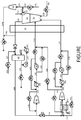
- FIGURE shows a flow diagram of a power production system and method according to an exemplary embodiment of the present disclosure including a bypass line configured for passage of compressed oxidant to the recycle flow line during a startup stage, said flow being configured for shut-off once desired operating parameters are achieved.
- the present disclosure relates to systems and methods that provide power generation using predominantly CO 2 as a working fluid.
- the process uses a high pressure/low pressure ratio turbine that expands a mixture of a high pressure recycle CO 2 stream and combustion products arising from combustion of the fuel.
- Any fossil fuel particularly carbonaceous fuels, may be used.
- Non-limiting examples include natural gas, compressed gases, fuel gases (e.g., comprising one or more of H 2 , CO, CH 4 , H 2 S, and NH 3 ) and like combustible gases.
- Solid fuels ⁇ e.g., coal, lignite, petroleum coke, bitumen, biomass, and the like, or viscous liquid fuels may be used as well with incorporation of necessary system elements.
- a partial oxidation combustor can be used to convert the solid or viscous liquid fuel to a fuel gas that is substantially free of solid particles.
- All fuel and combustion derived impurities such as sulfur compounds, NO, NO 2 , CO 2 , H 2 O, Hg, and the like can be separated for disposal with substantially or completely no emissions to the atmosphere. Pure oxygen can be used as the oxidant in the combustion process.
- the hot turbine exhaust is used to partially preheat the high pressure recycle CO 2 stream.
- the recycle CO 2 stream can be further heated using additive heating that can be derived from a variety of sources (e.g., from an air separation unit or from the compression energy of a CO 2 compressor).
- a power production method can comprise passing a compressed, heated recycle CO 2 stream into a combustor.
- the compressed, heated recycle CO 2 stream can be formed as further described below.
- a fuel can be combusted with oxygen (e.g., at least 98% or at least 99% pure O 2 ) in the presence of the recycle CO 2 stream to produce a CO 2 containing stream.
- the CO 2 containing stream from the combustor can have a temperature of about 500 °C or greater (e.g., about 500 °C to about 1,700 °C) and a pressure of about 150 bar (15 MPa) or greater (e.g., about 150 bar (15 MPa) to about 500 bar (50 MPa).
- the CO 2 containing stream can be passed through a turbine to expand the CO 2 containing stream, generate power, and form a turbine exhaust stream comprising CO 2 .
- the CO 2 containing stream can be expanded across the turbine at a desired pressure ratio.
- the turbine exhaust stream can be processed to remove combustion products and any net CO 2 produced by combustion of the fuel.
- the turbine exhaust stream can be cooled by passage through a heat exchanger.
- Any suitable heat exchanger suitable for use under the temperature and pressure conditions described herein can be utilized.
- the heat exchanger can comprise a series of at least two, at least three, or even more economizer heat exchangers.
- a single heat exchanger with at least two sections, at least three sections (or even more sections) can be used.
- the heat exchanger may be described has having at least three heat exchange sections operating across different temperature ranges. Withdrawn heat from the turbine exhaust stream can be utilized for heating the recycle CO 2 stream as described below.
- the turbine exhaust stream can be divided into two or more portions.
- the first portion can comprise 50% or greater, 70% or greater, or 90% or greater (but less than 100%) of the total mass flow of the turbine exhaust stream. All or a portion of the turbine exhaust stream can be passed through a separator to remove water and can be further treated to remove other combustion products or impurities.
- the resulting stream can be described as a main recycle CO 2 stream.
- a portion of the main recycle CO 2 stream can be combined with oxygen to form the oxidant stream, which can be compressed in one or more stages to the desired combustor input pressure.
- a portion of the main recycle CO 2 stream can be compressed such as in a multi-stage compressor with intercooling between the stages.
- the main recycle CO 2 stream (alone or combined with the oxygen) is compressed to a pressure of about 40 bar (4 MPa) to about 400 bar (40 MPa), about 80 bar (8 MPa) to about 200 bar (20 MPa), or about 100 bar (10 MPa) to about 150 bar (15 MPa).
- the compressed recycle CO 2 stream is then passed back through the heat exchangers to be heated.
- the compressed recycle CO 2 stream is heated using the heat withdrawn from the turbine exhaust stream (which can be characterized as the heat of combustion that remains in the turbine exhaust stream).
- additional heat e.g., heat of compression
- the use of the additive heating can be beneficial to reduce temperature differential between the turbine exhaust stream and the heated, compressed recycle CO 2 stream leaving the heat exchanger and entering the combustor to about 30 °C or less, about 25 °C or less, or about 20 °C or less, such as about 2 °C to about 20 °C, or about 2 °C to about 10 °C.
- FIG. 1 illustrates a flow diagram of a power production system and method according to the present disclosure wherein a bypass line is included.
- the bypass line provides for passage of compressed oxidant to the recycle flow line, such bypass flow being controllable via one or more valves such that the flow can be turned on during startup and turned off once desired operating parameters are achieved.
- flow of CO 2 recycle stream from the shaft-driven compressor can be shut off so that the CO 2 recycle stream is not passing into the recycle flow line.
- the CO 2 recycle stream may be exhausted during startup, or this flow may be allowed to recycle around the shaft-driven compressor to allow the compressor to move from idle to a point to within its operational range.
- Such configuration during startup is desirable because the shaft-driven compressor that is utilized to compress the CO 2 recycle stream cannot provide the required flow volume and flow pressure to properly regulate the combustion temperature in the combustor until the speed of the shaft shared by the compressor and the turbine is functioning at the turbine threshold speed or greater.
- the oxidant compressor can be a motor-driven compressor and, as such, may be operated so as to provide the required flow volume and flow pressure for input to the combustor, even during the startup time wherein the shaft speed is below the turbine threshold speed.
- combustion chemistry during this startup stage would be different than the combustion chemistry during normal power production operation. This is because a greater percentage of oxidant is being utilized in the combustor than would be present if the CO 2 recycle stream was being flowed to the combustor. Since the startup stage is sufficiently short in duration, the difference in combustion chemistry is not detrimental to the overall system and methods. In addition, this chemistry is quickly diluted once the system is operating under normal operating parameters.
- the bypass line can be closed, and flow of the CO 2 recycle stream can begin to pass through the recycle flow line to the combustor for normal operation.
- the turbine threshold speed can be about 50% or greater of the speed at which the turbine operates in the normal, power production mode. In further embodiments, the turbine threshold speed can be about 60% or greater, about 70% or greater, about 80% or greater, about 85% or greater, or about 90% or greater of the speed at which the turbine operates in the normal, power production mode.
- the bypass line can be closed.
- a valve in the line may be closed.
- the flow controller for the CO 2 recycle stream compressor will cause the CO 2 recycle stream to begin to flow into and through the recycle flow line and to the combustor. In this manner, the flow regulating the combustion temperature is continuous even though the chemistry may be changing as the oxidant stream is replaced by the CO 2 recycle stream.
- natural gas (NG) fuel passes through valve 1 and line 120 into the combustor 15 where it is combusted with oxygen in the presence of CO 2 to form a combustion product stream that is expanded in the turbine 20 to produce turbine exhaust stream 126.
- Air from air source 22a passes through the gland seal 21 to combine with exhaust from the turbine escaping around the gland seal and form stream 122, which becomes stream 123, and which is compressed in the gland seal compressor 23 to form stream 124a.
- valve 2 is opened and air from air source 22b exits valve 2 as air stream 121, which air stream mixes with stream 122 to form stream 123, which stream can contain a large fraction of air.
- the system can be configured for preferential flow of one or more streams through one or more valves.
- line 124a and line 126 (after exiting the heat exchanger 30) can be configured relative to valve 3 such that line 124a is closer to the valve than line 126. This allows the vent flow through valve 3 to preferentially use the flow from line 124a, instead of the flow from line 126.
- the configuration can be adjusted to provide desired flow mixtures as desired. Because of this, any contaminants which enter the system from air ingress 22a or 22b can be minimized since the contaminants can be preferentially sent to the vent (valve 3).
- operation of gland seal compressor 23 can also minimize air leakage and therefore contaminants entering the system.
- the turbine exhaust stream 126 is cooled in the heat exchanger 30, and any portion of stream 124a not vented through valve 3 can be combined with the cooled turbine exhaust stream 126 through stream 124b.
- CO 2 from CO 2 source 115 passes through valve 4 and line 127 and is combined with the cooled turbine exhaust stream 126 before passage through the separator 40.
- Water stream 125 from the separator 40 can be drawn off through valve 6 and/or compressed in pump 90 to form stream 147, which is cooled in water cooler 101 to form stream 148 that is recycled into the separator.
- Substantially pure CO 2 exits the separator 40 as a recycle stream in line 128 and is compressed in main compressor 50 to form compressed CO 2 recycle stream 130 that is cooled in water cooler 102 to form stream 131 that passes through main pump 60 and is directed to the combustor 15 in recycle line 133 passing through valve 13.
- a portion of stream 130 may pass through valve 8 and line 135 for recirculation through the main compressor 50.
- a portion of the compressed CO 2 recycle stream from recycle line 133 may be drawn off in line 134 upstream of valve 13 and passed through valve 9 for recirculation through the water cooler 102.
- the CO 2 recycle stream in line 131 may bypass the pump 60 in pump bypass line 132 which includes the exit valve 12 for the main compressor 50.
- a portion of the CO 2 recycle stream from line 128 may pass through valve 7 to line 136 to combine with oxygen from oxygen source 205 through valve 5 and line 137 to form oxidant stream 138.
- the oxidant stream 138 (a O 2 /CO 2 mixture) is passed through heat exchanger 103 to form stream 139, which is compressed in the oxidant compressor 70 and exits in line 140.
- a portion of the compressed oxidant stream from line 140 may pass in line 141 through valve 10 for recirculation through the heat exchanger 103.
- the oxidant stream 138 may be heated or cooled.
- input 201 may be a cold water stream that exits as heated output 202 such that oxidant stream 139 is cooled relative to stream 138.
- input 201 may be a hot water stream that exits as cooled output 202 such that oxidant stream 139 is heated relative to stream 138.
- Compressed oxidant in line 140 passes through water cooler 104 to form stream 142, which passes through O 2 /CO 2 pump 80 and valve 16 before the oxidant passes through oxidant line 144 to the combustor 15 for combustion of the fuel therein.
- Oxidant can bypass the pump 80 in oxidant bypass line 143 through the oxidant exhaust valve 17.
- Startup bypass line 146 interconnects line 141 and pump bypass line 132 and includes valve 14.
- the exit valve 12 for the main compressor 50 is closed (as are valve 9 in lines 134 and valve 13 in recycle line 133).
- the CO 2 recycle stream 128 does not pass for recycle to the combustor 15.
- Oxygen flowing through valve 5 and line 137 (and mixing with recycled CO 2 from line 136) is cooled (or heated) in heat exchanger 103 and compressed in oxidant compressor 70 (which can be a motor-driven compressor).
- a portion of the compressed oxidant (mixed O 2 /CO 2 ) from line 140 is cooled in cooler 104 and bypasses pump 80 in pump bypass line 143 (with valve 17 open and valve 16 closed) to pass through oxidant line 144 to the combustor.
- a portion of the compressed oxidant from line 140 also passes through line 141 to the startup bypass line 146. Since the exit valve 12 for the main compressor is closed, the oxidant that would otherwise combine with the CO 2 passing through the pump bypass line 132 passes through the recycle line 133 to the combustor 15. Operation proceeds in this fashion until the turbine has achieved the turbine threshold value and the shaft for the shaft-driven compressor 50 is thus working at a sufficient speed for the shaft-driven compressor 50 to provide the CO 2 recycle stream at a sufficient flow volume and flow pressure. At that point, the bypass line valve 14 is closed, and the exit valve 12 for the main compressor is opened. Oxidant no longer passes through the recycle line 133 and only passes through the oxidant line 144. With the turbine operating at a speed above the threshold speed, the compressor 50 provides the CO 2 recycle stream through recycle line 133 at the required flow volume and flow pressure for input to the combustor 15.
- two different turbine threshold speeds may be utilized to provide a gradual changeover from the startup stage to the normal power production stage.
- a first turbine threshold speed may be utilized to trigger closing of the bypass line valve (and thus opening of the main compressor exhaust valve). Closing and opening of the valves may not be immediate.
- a second turbine threshold may be achieved at which point the bypass line valve may be completely closed.
- the oxygen supply to the oxidant compressor 70 can be supplied to the compressor via the air ingress at stream 121 instead of through the oxygen supply at stream 137.
- gland seal compressor 23 will effectively fill the plant with air while valves 4 and 5 are closed.
- Oxidant compressor 70 will still supply the turbine with an oxidant flow (air, in such embodiments) through stream 144 and through the bypass via stream 133.
- CO 2 from the CO 2 supply 115 entering through valve 4 and stream 127 can be connected to the suction of gland seal compressor 23.
- valve 4 will be open while air will pass through valve 2.
- the plant will fill with an air and CO 2 mixture with oxidant compressor 70 still controlling the supply of fluids through streams 144 and 133.
Landscapes
- Engineering & Computer Science (AREA)
- Chemical & Material Sciences (AREA)
- Combustion & Propulsion (AREA)
- Mechanical Engineering (AREA)
- General Engineering & Computer Science (AREA)
- Life Sciences & Earth Sciences (AREA)
- Sustainable Development (AREA)
- Chemical Kinetics & Catalysis (AREA)
- Engine Equipment That Uses Special Cycles (AREA)
- Control Of Turbines (AREA)
- Physics & Mathematics (AREA)
- Thermal Sciences (AREA)
Claims (11)
- Système de production d'énergie comprenant :une chambre de combustion (15) ;une turbine (20) ;un premier compresseur (50) sur un arbre commun avec la turbine (20) ;un compresseur d'oxydant (70) ;une conduite d'écoulement d'échappement (126, 128) configurée pour le passage d'un flux d'échappement de turbine depuis la turbine (20) jusqu'au premier compresseur (50) ;une conduite d'écoulement de recyclage (133) configurée pour le passage d'un flux de recyclage de CO2 depuis le premier compresseur (50) jusqu'à la chambre de combustion (15) ;une conduite d'écoulement d'oxydant (140, 142, 144) configurée pour le passage d'un flux d'oxydant depuis le compresseur d'oxydant (70) jusqu'à la chambre de combustion (15) ;une conduite de dérivation (141, 146) configurée pour un passage contrôlable d'au moins une portion du flux d'oxydant depuis la conduite d'écoulement d'oxydant (140, 142, 144) jusqu'à la conduite d'écoulement de recyclage (133) ;caractérisé en ce que la turbine (20) inclut un presse-étoupe d'étanchéité (21) et une entrée d'air ; etun compresseur de presse-étoupe d'étanchéité (23) configuré pour recevoir et compresser un flux d'air et un échappement de turbine depuis le presse-étoupe d'étanchéité (21).
- Système de production d'énergie selon la revendication 1, dans lequel la conduite de dérivation (146) inclut une vanne (14).
- Système de production d'énergie selon la revendication 2, dans lequel la vanne de conduite de dérivation (14) est configurée pour être ouverte au-dessous d'une première vitesse seuil de turbine, ou dans lequel la vanne de conduite de dérivation (14) est configurée pour être fermée au-dessus d'une seconde vitesse seuil de turbine.
- Système de production d'énergie selon la revendication 1, comprenant en outre un échangeur de chaleur à récupération (30).
- Système de production d'énergie selon la revendication 4, dans lequel la conduite d'écoulement d'échappement (126, 128), la conduite d'écoulement de recyclage (133) et la conduite d'écoulement d'oxydant (140, 142, 144) sont configurées pour le passage de leurs flux respectifs à travers l'échangeur de chaleur à récupération (30).
- Système de production d'énergie selon la revendication 1, dans lequel l'une ou les deux des conditions suivantes sont remplies :le premier compresseur (50) est un compresseur entraîné par arbre ;le compresseur d'oxydant (70) est un compresseur entraîné par moteur.
- Système de production d'énergie selon la revendication 1, comprenant en outre un évent (3) dans un agencement avec le compresseur de presse-étoupe d'étanchéité (23) et une conduite d'évent (124a) entre le compresseur de presse-étoupe d'étanchéité (23) et l'évent (3).
- Système de production d'énergie selon la revendication 7, dans lequel la conduite d'évent (124a) entre le compresseur de presse-étoupe d'étanchéité (23) et l'évent (3) est dans un agencement d'écoulement avec la conduite d'écoulement d'échappement (126, 128), et dans lequel la conduite d'évent (124a) et la conduite d'écoulement d'échappement (126, 128) sont agencées par rapport à l'évent (3) pour un écoulement préférentiel jusqu'à l'évent (3) depuis les conduites respectives.
- Méthode de démarrage d'une installation de production d'énergie, la méthode comprenant :la pressurisation d'un flux d'oxydant dans un compresseur d'oxydant (70) qui est entraîné par moteur, l'oxydant entrant dans le compresseur d'oxydant (70) étant de l'air ;le passage de l'oxydant pressurisé depuis le compresseur d'oxydant (70) jusqu'à une chambre de combustion (15) à travers une conduite d'écoulement d'oxydant (140, 142, 144) ;la combustion d'un combustible avec l'oxydant dans la chambre de combustion (15) ;la dilatation du flux de produit de combustion depuis la chambre de combustion (15) dans une turbine (20) qui inclut un presse-étoupe d'étanchéité (21), une entrée d'air (22a), et un compresseur de presse-étoupe d'étanchéité (23) configuré pour recevoir et compresser un flux d'air et un échappement de turbine depuis le presse-étoupe d'étanchéité (21) ;le refroidissement d'un flux d'échappement de turbine depuis la turbine (20) dans un échangeur de chaleur à récupération (30) ;l'enlèvement de l'eau du flux d'échappement de turbine pour former un flux de recyclage de CO2 ; etla compression du flux de recyclage de CO2 dans un compresseur entraîné par arbre (50) sur un arbre commun avec la turbine (20) pour former un flux de recyclage de CO2 compressé configuré pour passer dans la chambre à combustion (15) dans une conduite d'écoulement de recyclage (130, 131, 133) ;dans laquelle le flux de recyclage de CO2 compressé est fait recirculer et un oxydant provenant du compresseur d'oxydant entraîné par moteur (70) est fait passer à travers la conduite d'écoulement de recyclage (130, 131, 133) jusqu'à la chambre à combustion (15) jusqu'à ce que la turbine (20) atteigne une vitesse seuil prédéfinie.
- Méthode selon la revendication 9, dans laquelle l'une ou les deux des conditions suivantes sont remplies :la vitesse seuil définie est environ 85 % de la vitesse normale de fonctionnement ;sensiblement pas de flux de recyclage de CO2 compressé n'est fait passer dans la chambre de combustion (15), à travers la conduite d'écoulement de recyclage (130, 131, 133), jusqu'à ce que la turbine (20) atteigne la vitesse seuil définie.
- Méthode selon la revendication 9, dans laquelle l'oxydant entrant dans le compresseur d'oxydant (70) est un mélange d'O2 et de CO2.
Priority Applications (1)
| Application Number | Priority Date | Filing Date | Title |
|---|---|---|---|
| PL16738244T PL3308004T3 (pl) | 2015-06-15 | 2016-06-13 | Układ i sposób uruchamiania elektrowni |
Applications Claiming Priority (2)
| Application Number | Priority Date | Filing Date | Title |
|---|---|---|---|
| US201562175886P | 2015-06-15 | 2015-06-15 | |
| PCT/US2016/037192 WO2016205116A1 (fr) | 2015-06-15 | 2016-06-13 | Système et procédé pour le démarrage d'une installation de production d'énergie |
Publications (2)
| Publication Number | Publication Date |
|---|---|
| EP3308004A1 EP3308004A1 (fr) | 2018-04-18 |
| EP3308004B1 true EP3308004B1 (fr) | 2021-09-29 |
Family
ID=56409142
Family Applications (1)
| Application Number | Title | Priority Date | Filing Date |
|---|---|---|---|
| EP16738244.9A Active EP3308004B1 (fr) | 2015-06-15 | 2016-06-13 | Système et procédé pour le démarrage d'une installation de production d'énergie |
Country Status (15)
| Country | Link |
|---|---|
| US (1) | US10533461B2 (fr) |
| EP (1) | EP3308004B1 (fr) |
| JP (2) | JP6959870B2 (fr) |
| KR (1) | KR102602774B1 (fr) |
| CN (1) | CN107849976B (fr) |
| AU (1) | AU2016277834B2 (fr) |
| BR (1) | BR112017027018B1 (fr) |
| CA (1) | CA2989618A1 (fr) |
| EA (1) | EA036619B1 (fr) |
| ES (1) | ES2898863T3 (fr) |
| MX (1) | MX2017016478A (fr) |
| MY (1) | MY188544A (fr) |
| PL (1) | PL3308004T3 (fr) |
| WO (1) | WO2016205116A1 (fr) |
| ZA (1) | ZA201800183B (fr) |
Families Citing this family (12)
| Publication number | Priority date | Publication date | Assignee | Title |
|---|---|---|---|---|
| US10961920B2 (en) | 2018-10-02 | 2021-03-30 | 8 Rivers Capital, Llc | Control systems and methods suitable for use with power production systems and methods |
| US11686258B2 (en) | 2014-11-12 | 2023-06-27 | 8 Rivers Capital, Llc | Control systems and methods suitable for use with power production systems and methods |
| US10480403B2 (en) * | 2016-02-22 | 2019-11-19 | King Fahd University Of Petroleum And Minerals | Combustor with adjustable swirler and a combustion system |
| MX2018010310A (es) | 2016-02-26 | 2019-05-02 | 8 Rivers Capital Llc | Sistemas y metodos para controlar una planta de energia. |
| FR3052684A1 (fr) * | 2016-06-16 | 2017-12-22 | L'air Liquide Sa Pour L'etude Et L'exploitation Des Procedes Georges Claude | Appareil et procede de separation de co2 a basse temperature comprenant une etape de separation par permeation |
| US11199327B2 (en) | 2017-03-07 | 2021-12-14 | 8 Rivers Capital, Llc | Systems and methods for operation of a flexible fuel combustor |
| EP3438585A3 (fr) * | 2017-08-03 | 2019-04-17 | L'air Liquide, Societe Anonyme Pour L'etude Et L'exploitation Des Procedes Georges Claude | Procédé de dégivrage d'un appareil de séparation d'air par distillation cryogénique et appareil adapté pour être dégivré par ce procédé |
| EP3827163A1 (fr) | 2018-07-23 | 2021-06-02 | 8 Rivers Capital, LLC | Système et procédé de production d'énergie avec une combustion sans flamme |
| MX2022004844A (es) | 2019-10-22 | 2022-05-18 | 8 Rivers Capital Llc | Esquemas de control y metodos para la regulacion termica de sistemas de produccion de energia. |
| JP7371572B2 (ja) | 2020-05-27 | 2023-10-31 | コニカミノルタ株式会社 | 緩衝部材、緩衝部材の製造方法及び梱包体 |
| WO2022160060A1 (fr) * | 2021-01-29 | 2022-08-04 | Industriasys Corp. | Procédés et systèmes de génération d'énergie à émission nulle |
| WO2024012715A1 (fr) * | 2022-07-15 | 2024-01-18 | Nuovo Pignone Tecnologie - S.R.L. | Installation pour conversion à haut rendement de combustible en énergie mécanique |
Family Cites Families (200)
| Publication number | Priority date | Publication date | Assignee | Title |
|---|---|---|---|---|
| US3376706A (en) | 1965-06-28 | 1968-04-09 | Angelino Gianfranco | Method for obtaining mechanical energy from a thermal gas cycle with liquid phase compression |
| US3369361A (en) | 1966-03-07 | 1968-02-20 | Gale M. Craig | Gas turbine power plant with sub-atmospheric spray-cooled turbine discharge into exhaust compressor |
| CH476208A (de) | 1967-07-27 | 1969-07-31 | Sulzer Ag | Gasturbinenanlage mit CO2 als Arbeitsmittel |
| US3544291A (en) | 1968-04-22 | 1970-12-01 | Texaco Inc | Coal gasification process |
| US3736745A (en) | 1971-06-09 | 1973-06-05 | H Karig | Supercritical thermal power system using combustion gases for working fluid |
| US3816595A (en) | 1971-11-15 | 1974-06-11 | Aqua Chem Inc | Method and apparatus for removing nitrogen oxides from a gas stream |
| US3868817A (en) | 1973-12-27 | 1975-03-04 | Texaco Inc | Gas turbine process utilizing purified fuel gas |
| US3971211A (en) | 1974-04-02 | 1976-07-27 | Mcdonnell Douglas Corporation | Thermodynamic cycles with supercritical CO2 cycle topping |
| US3976443A (en) | 1974-12-18 | 1976-08-24 | Texaco Inc. | Synthesis gas from solid carbonaceous fuel |
| US4132065A (en) | 1977-03-28 | 1979-01-02 | Texaco Inc. | Production of H2 and co-containing gas stream and power |
| US4191500A (en) | 1977-07-27 | 1980-03-04 | Rockwell International Corporation | Dense-phase feeder method |
| US4154581A (en) | 1978-01-12 | 1979-05-15 | Battelle Development Corporation | Two-zone fluid bed combustion or gasification process |
| US4206610A (en) | 1978-04-14 | 1980-06-10 | Arthur D. Little, Inc. | Method and apparatus for transporting coal as a coal/liquid carbon dioxide slurry |
| US4193259A (en) | 1979-05-24 | 1980-03-18 | Texaco Inc. | Process for the generation of power from carbonaceous fuels with minimal atmospheric pollution |
| US4702747A (en) | 1981-03-24 | 1987-10-27 | Carbon Fuels Corporation | Coal derived/carbon dioxide fuel slurry and method of manufacture |
| US4434613A (en) * | 1981-09-02 | 1984-03-06 | General Electric Company | Closed cycle gas turbine for gaseous production |
| US4522628A (en) | 1981-12-16 | 1985-06-11 | Mobil Oil Corporation | Method for removing ash mineral matter of coal with liquid carbon dioxide and water |
| US4498289A (en) | 1982-12-27 | 1985-02-12 | Ian Osgerby | Carbon dioxide power cycle |
| US4602483A (en) | 1985-03-08 | 1986-07-29 | Southwestern Public Service Company | Coal slurry system |
| US4765781A (en) | 1985-03-08 | 1988-08-23 | Southwestern Public Service Company | Coal slurry system |
| DE3600432A1 (de) | 1985-05-21 | 1987-02-05 | Gutehoffnungshuette Man | Verfahren zum vergasen eines kohlenstoffhaltigen brennstoffs, insbesondere kohle |
| US4721420A (en) | 1985-09-03 | 1988-01-26 | Arthur D. Little, Inc. | Pipeline transportation of coarse coal-liquid carbon dioxide slurry |
| US4735052A (en) | 1985-09-30 | 1988-04-05 | Kabushiki Kaisha Toshiba | Gas turbine apparatus |
| GB2196016B (en) | 1986-08-29 | 1991-05-15 | Humphreys & Glasgow Ltd | Clean electric power generation process |
| US4999995A (en) | 1986-08-29 | 1991-03-19 | Enserch International Investments Ltd. | Clean electric power generation apparatus |
| US4765143A (en) | 1987-02-04 | 1988-08-23 | Cbi Research Corporation | Power plant using CO2 as a working fluid |
| US4839030A (en) | 1988-05-27 | 1989-06-13 | Hri, Inc. | Coal liquefaction process utilizing coal/CO2 slurry feedstream |
| US4957515A (en) | 1988-11-03 | 1990-09-18 | Air Products And Chemicals, Inc. | Process for sulfur removal and recovery from fuel gas using physical solvent |
| JP2664984B2 (ja) | 1989-02-28 | 1997-10-22 | 三菱重工業株式会社 | 難燃性低発熱量ガスの燃焼装置 |
| US5247791A (en) | 1989-10-25 | 1993-09-28 | Pyong S. Pak | Power generation plant and power generation method without emission of carbon dioxide |
| US5175995A (en) | 1989-10-25 | 1993-01-05 | Pyong-Sik Pak | Power generation plant and power generation method without emission of carbon dioxide |
| JP2954972B2 (ja) | 1990-04-18 | 1999-09-27 | 三菱重工業株式会社 | ガス化ガス燃焼ガスタービン発電プラント |
| US5353721A (en) | 1991-07-15 | 1994-10-11 | Manufacturing And Technology Conversion International | Pulse combusted acoustic agglomeration apparatus and process |
| US5421166A (en) | 1992-02-18 | 1995-06-06 | Air Products And Chemicals, Inc. | Integrated air separation plant-integrated gasification combined cycle power generator |
| EP0642611B1 (fr) | 1992-05-29 | 1998-07-15 | Kvaerner Pulping Ab | Procede de recuperation d'energie dans un gaz combustible |
| US5295350A (en) | 1992-06-26 | 1994-03-22 | Texaco Inc. | Combined power cycle with liquefied natural gas (LNG) and synthesis or fuel gas |
| NL9201179A (nl) | 1992-07-02 | 1994-02-01 | Tno | Werkwijze voor het regeneratief verwijderen van kooldioxide uit gasstromen. |
| CH686525A5 (de) * | 1992-07-02 | 1996-04-15 | Escher Wyss Ag | Turbomaschine . |
| JPH0626362A (ja) | 1992-07-09 | 1994-02-01 | Mitsubishi Heavy Ind Ltd | Co▲2▼ガスタービンサイクル |
| SE9202155L (sv) | 1992-07-13 | 1993-08-16 | Bal Ab | Kombinerad foerbraennings- och avgasreningsanlaeggning |
| US6289666B1 (en) | 1992-10-27 | 2001-09-18 | Ginter Vast Corporation | High efficiency low pollution hybrid Brayton cycle combustor |
| US5937652A (en) | 1992-11-16 | 1999-08-17 | Abdelmalek; Fawzy T. | Process for coal or biomass fuel gasification by carbon dioxide extracted from a boiler flue gas stream |
| US5415673A (en) | 1993-10-15 | 1995-05-16 | Texaco Inc. | Energy efficient filtration of syngas cooling and scrubbing water |
| US5345756A (en) | 1993-10-20 | 1994-09-13 | Texaco Inc. | Partial oxidation process with production of power |
| US5417052A (en) | 1993-11-05 | 1995-05-23 | Midwest Research Institute | Hybrid solar central receiver for combined cycle power plant |
| JP3454372B2 (ja) | 1994-02-04 | 2003-10-06 | 石川島播磨重工業株式会社 | クローズドサイクルガスタービンの燃焼方法及び装置 |
| DE4407619C1 (de) | 1994-03-08 | 1995-06-08 | Entec Recycling Und Industriea | Verfahren zur schadstoffarmen Umwandlung fossiler Brennstoffe in technische Arbeit |
| JPH10505145A (ja) | 1994-08-25 | 1998-05-19 | クリーン エナジー システムズ, インコーポレイテッド | 汚染を減少した動力発生システム及びそのためのガス発生機 |
| DE4435322B4 (de) * | 1994-10-01 | 2005-05-04 | Alstom | Verfahren und Vorrichtung zur Wellendichtung und zur Kühlung auf der Abgasseite einer axialdurchströmten Gasturbine |
| GB9425691D0 (en) | 1994-12-20 | 1995-02-22 | Boc Group Plc | A combustion apparatus |
| US5595059A (en) | 1995-03-02 | 1997-01-21 | Westingthouse Electric Corporation | Combined cycle power plant with thermochemical recuperation and flue gas recirculation |
| US6170264B1 (en) | 1997-09-22 | 2001-01-09 | Clean Energy Systems, Inc. | Hydrocarbon combustion power generation system with CO2 sequestration |
| US5724805A (en) | 1995-08-21 | 1998-03-10 | University Of Massachusetts-Lowell | Power plant with carbon dioxide capture and zero pollutant emissions |
| US5906806A (en) | 1996-10-16 | 1999-05-25 | Clark; Steve L. | Reduced emission combustion process with resource conservation and recovery options "ZEROS" zero-emission energy recycling oxidation system |
| EP0859136A1 (fr) | 1997-02-17 | 1998-08-19 | N.V. Kema | Turbine à gaz à récupération d'énergie |
| NO308400B1 (no) | 1997-06-06 | 2000-09-11 | Norsk Hydro As | Kraftgenereringsprosess omfattende en forbrenningsprosess |
| EP0939199B1 (fr) | 1998-02-25 | 2004-03-31 | ALSTOM Technology Ltd | Centrale d'énergie et procédé de fonctionnement d'une centrale d'énergie avec un cycle de CO2 |
| EP0949405B1 (fr) | 1998-04-07 | 2006-05-31 | Mitsubishi Heavy Industries, Ltd. | Centrale à turbines |
| DK0953748T3 (da) | 1998-04-28 | 2004-06-07 | Alstom Switzerland Ltd | Kraftværksanlæg med en CO2-proces |
| US6148602A (en) | 1998-08-12 | 2000-11-21 | Norther Research & Engineering Corporation | Solid-fueled power generation system with carbon dioxide sequestration and method therefor |
| JP2000120447A (ja) | 1998-10-12 | 2000-04-25 | Toshiba Corp | 火力発電プラント |
| US6064122A (en) * | 1998-11-05 | 2000-05-16 | Alliedsignal Power Systems Inc. | Microturbine power of generating system including a battery source for supplying startup power |
| US6199364B1 (en) | 1999-01-22 | 2001-03-13 | Alzeta Corporation | Burner and process for operating gas turbines with minimal NOx emissions |
| US6209307B1 (en) | 1999-05-05 | 2001-04-03 | Fpl Energy, Inc. | Thermodynamic process for generating work using absorption and regeneration |
| JP2001041007A (ja) * | 1999-05-26 | 2001-02-13 | Mitsubishi Heavy Ind Ltd | タービン設備 |
| JP2000337107A (ja) | 1999-05-27 | 2000-12-05 | Mitsubishi Heavy Ind Ltd | クローズドガスタービンプラント |
| US6202574B1 (en) | 1999-07-09 | 2001-03-20 | Abb Alstom Power Inc. | Combustion method and apparatus for producing a carbon dioxide end product |
| JP4094185B2 (ja) | 1999-08-24 | 2008-06-04 | 三井造船株式会社 | 冷熱利用発電システム |
| NL1013804C2 (nl) | 1999-12-09 | 2001-06-12 | Wouter Willem Van De Waal | Milieuvriendelijke werkwijze voor het opwekken van energie uit aardgas. |
| US6196000B1 (en) | 2000-01-14 | 2001-03-06 | Thermo Energy Power Systems, Llc | Power system with enhanced thermodynamic efficiency and pollution control |
| DE10016079A1 (de) | 2000-03-31 | 2001-10-04 | Alstom Power Nv | Verfahren zum Entfernen von Kohlendioxid aus dem Abgas einer Gasturbinenanlage sowie Vorrichtung zur Durchführung des Verfahrens |
| WO2001090548A1 (fr) | 2000-05-12 | 2001-11-29 | Clean Energy Systems, Inc. | Systemes de generation d'energie par turbine a gaz a cycle de brayton semi-ferme |
| SE518487C2 (sv) | 2000-05-31 | 2002-10-15 | Norsk Hydro As | Metod att driva en förbränningsanläggning samt en förbränningsanläggning |
| US6333015B1 (en) | 2000-08-08 | 2001-12-25 | Arlin C. Lewis | Synthesis gas production and power generation with zero emissions |
| DE10064270A1 (de) | 2000-12-22 | 2002-07-11 | Alstom Switzerland Ltd | Verfahren zum Betrieb einer Gasturbinenanlage sowie eine diesbezügliche Gasturbinenanlage |
| FR2819584B1 (fr) | 2001-01-12 | 2003-03-07 | Air Liquide | Procede integre de separation d'air et de generation d'energie et installation pour la mise en oeuvre d'un tel procede |
| FR2819583B1 (fr) | 2001-01-12 | 2003-03-07 | Air Liquide | Procede integre de separation d'air et de generation d'energie et installation pour la mise en oeuvre d'un tel procede |
| US6532743B1 (en) | 2001-04-30 | 2003-03-18 | Pratt & Whitney Canada Corp. | Ultra low NOx emissions combustion system for gas turbine engines |
| US20030221409A1 (en) | 2002-05-29 | 2003-12-04 | Mcgowan Thomas F. | Pollution reduction fuel efficient combustion turbine |
| DE50207526D1 (de) | 2001-10-01 | 2006-08-24 | Alstom Technology Ltd | Verfahren und vorrichtung zum anfahren von emissionsfreien gasturbinenkraftwerken |
| WO2003049122A2 (fr) | 2001-12-03 | 2003-06-12 | Clean Energy Systems, Inc. | Systemes de production alimente en charbon et en gaz de synthese a emission atmospherique zero |
| JP3814206B2 (ja) | 2002-01-31 | 2006-08-23 | 三菱重工業株式会社 | 二酸化炭素回収プロセスの排熱利用方法 |
| US7284362B2 (en) | 2002-02-11 | 2007-10-23 | L'Air Liquide, Société Anonyme à Directoire et Conseil de Surveillance pour l'Étude et l'Exploitation des Procedes Georges Claude | Integrated air separation and oxygen fired power generation system |
| US6871502B2 (en) | 2002-02-15 | 2005-03-29 | America Air Liquide, Inc. | Optimized power generation system comprising an oxygen-fired combustor integrated with an air separation unit |
| US6532745B1 (en) | 2002-04-10 | 2003-03-18 | David L. Neary | Partially-open gas turbine cycle providing high thermal efficiencies and ultra-low emissions |
| NO20023050L (no) | 2002-06-21 | 2003-12-22 | Fleischer & Co | Fremgangsmåte samt anlegg for utf degree relse av fremgangsmåten |
| US20040011057A1 (en) | 2002-07-16 | 2004-01-22 | Siemens Westinghouse Power Corporation | Ultra-low emission power plant |
| US6820689B2 (en) | 2002-07-18 | 2004-11-23 | Production Resources, Inc. | Method and apparatus for generating pollution free electrical energy from hydrocarbons |
| US6775987B2 (en) | 2002-09-12 | 2004-08-17 | The Boeing Company | Low-emission, staged-combustion power generation |
| US6802178B2 (en) | 2002-09-12 | 2004-10-12 | The Boeing Company | Fluid injection and injection method |
| AU2003260832A1 (en) | 2002-09-17 | 2004-04-08 | Foster Wheeler Energy Corporation | Advanced hybrid coal gasification cycle utilizing a recycled working fluid |
| US7303597B2 (en) | 2002-10-15 | 2007-12-04 | Pratt & Whitney Rocketdyne, Inc. | Method and apparatus for continuously feeding and pressurizing a solid material into a high pressure system |
| CA2505354C (fr) | 2002-11-08 | 2012-04-03 | Alstom Technology Ltd. | Centrale electrique a turbines a gaz et procede pour l'exploiter |
| US7191587B2 (en) | 2002-11-13 | 2007-03-20 | American Air Liquide, Inc. | Hybrid oxygen-fired power generation system |
| US6945029B2 (en) | 2002-11-15 | 2005-09-20 | Clean Energy Systems, Inc. | Low pollution power generation system with ion transfer membrane air separation |
| US6898936B1 (en) | 2002-12-04 | 2005-05-31 | The United States Of America As Represented By The United States Department Of Energy | Compression stripping of flue gas with energy recovery |
| US7007474B1 (en) | 2002-12-04 | 2006-03-07 | The United States Of America As Represented By The United States Department Of Energy | Energy recovery during expansion of compressed gas using power plant low-quality heat sources |
| EP1429000A1 (fr) | 2002-12-09 | 2004-06-16 | Siemens Aktiengesellschaft | Procédé et dispositif pour l'opération d'une turbine à gaz avec une chambre de combustion du combustible fossilisé |
| US6993912B2 (en) | 2003-01-23 | 2006-02-07 | Pratt & Whitney Canada Corp. | Ultra low Nox emissions combustion system for gas turbine engines |
| US7021063B2 (en) | 2003-03-10 | 2006-04-04 | Clean Energy Systems, Inc. | Reheat heat exchanger power generation systems |
| US7074033B2 (en) | 2003-03-22 | 2006-07-11 | David Lloyd Neary | Partially-open fired heater cycle providing high thermal efficiencies and ultra-low emissions |
| US7007486B2 (en) | 2003-03-26 | 2006-03-07 | The Boeing Company | Apparatus and method for selecting a flow mixture |
| GB2401403B (en) | 2003-05-08 | 2006-05-31 | Rolls Royce Plc | Carbon dioxide recirculation |
| DE10325111A1 (de) * | 2003-06-02 | 2005-01-05 | Alstom Technology Ltd | Verfahren zur Erzeugung von Energie in einer eine Gasturbine umfassende Energieerzeugungsanlage sowie Energieerzeugungsanlage zur Durchführung des Verfahrens |
| US7192569B2 (en) | 2003-06-30 | 2007-03-20 | Pratt & Whitney | Hydrogen generation with efficient byproduct recycle |
| EP1687518A1 (fr) | 2003-09-30 | 2006-08-09 | BHP Billiton Innovation Pty Ltd | Generation de puissance |
| US7469544B2 (en) | 2003-10-10 | 2008-12-30 | Pratt & Whitney Rocketdyne | Method and apparatus for injecting a fuel into a combustor assembly |
| US7017329B2 (en) | 2003-10-10 | 2006-03-28 | United Technologies Corporation | Method and apparatus for mixing substances |
| US7124589B2 (en) | 2003-12-22 | 2006-10-24 | David Neary | Power cogeneration system and apparatus means for improved high thermal efficiencies and ultra-low emissions |
| DE10360951A1 (de) | 2003-12-23 | 2005-07-28 | Alstom Technology Ltd | Wärmekraftanlage mit sequentieller Verbrennung und reduziertem CO2-Ausstoß sowie Verfahren zum Betreiben einer derartigen Anlage |
| US7111463B2 (en) | 2004-01-23 | 2006-09-26 | Pratt & Whitney Rocketdyne Inc. | Combustion wave ignition for combustors |
| FR2867463B1 (fr) | 2004-03-15 | 2007-05-11 | Commissariat Energie Atomique | Alimentation en solide de granulometrie variable d'un dispositif sous pression |
| US20050241311A1 (en) | 2004-04-16 | 2005-11-03 | Pronske Keith L | Zero emissions closed rankine cycle power system |
| EP2278222A1 (fr) | 2004-05-19 | 2011-01-26 | Innovative Energy, Inc. | Procédé et appareil de combustion |
| US7360639B2 (en) | 2004-06-16 | 2008-04-22 | Pratt & Whitney Rocketdyne, Inc. | Hot rotary screw pump |
| US7547419B2 (en) | 2004-06-16 | 2009-06-16 | United Technologies Corporation | Two phase injector for fluidized bed reactor |
| DE102004039164A1 (de) | 2004-08-11 | 2006-03-02 | Alstom Technology Ltd | Verfahren zur Erzeugung von Energie in einer eine Gasturbine umfassenden Energieerzeugungsanlage sowie Energieerzeugungsanlage zur Durchführung des Verfahrens |
| US7459131B2 (en) | 2004-08-16 | 2008-12-02 | United Technologies Corporation | Reduced temperature regernerating/calcining apparatus for hydrogen generation |
| US7402188B2 (en) | 2004-08-31 | 2008-07-22 | Pratt & Whitney Rocketdyne, Inc. | Method and apparatus for coal gasifier |
| JP2006125767A (ja) | 2004-10-29 | 2006-05-18 | Tokyo Institute Of Technology | 熱交換器 |
| US7736599B2 (en) | 2004-11-12 | 2010-06-15 | Applied Materials, Inc. | Reactor design to reduce particle deposition during process abatement |
| EP1657409A1 (fr) | 2004-11-15 | 2006-05-17 | Elsam A/S | Procédé et dispositif pour la production de l'électricité |
| EP1669572A1 (fr) | 2004-12-08 | 2006-06-14 | Vrije Universiteit Brussel | Procédé et installation de production d'énergie électrique |
| CA2590394A1 (fr) | 2004-12-13 | 2006-06-22 | F. Hoffmann-La Roche Ag | Polymorphisme a simple nucleotide (snp) |
| JP3110114U (ja) | 2005-01-31 | 2005-06-16 | 旭文 廖 | 防水型led発光装置 |
| US7269952B2 (en) | 2005-03-02 | 2007-09-18 | General Electric Company | Method and apparatus for gas turbine dry low NOx combustor corrected parameter control |
| US7547423B2 (en) | 2005-03-16 | 2009-06-16 | Pratt & Whitney Rocketdyne | Compact high efficiency gasifier |
| WO2006107209A1 (fr) | 2005-04-05 | 2006-10-12 | Sargas As | Centrale thermique avec une basse teneur en co2 |
| US8196848B2 (en) | 2005-04-29 | 2012-06-12 | Pratt & Whitney Rocketdyne, Inc. | Gasifier injector |
| US7717046B2 (en) | 2005-04-29 | 2010-05-18 | Pratt & Whitney Rocketdyne, Inc. | High pressure dry coal slurry extrusion pump |
| NO332159B1 (no) | 2006-01-13 | 2012-07-09 | Nebb Technology As | Fremgangsmate og anlegg for energieffektiv oppfanging og utskillelse av CO2 fra en gassfase |
| US7950243B2 (en) | 2006-01-16 | 2011-05-31 | Gurin Michael H | Carbon dioxide as fuel for power generation and sequestration system |
| US8075646B2 (en) | 2006-02-09 | 2011-12-13 | Siemens Energy, Inc. | Advanced ASU and HRSG integration for improved integrated gasification combined cycle efficiency |
| US7665291B2 (en) | 2006-04-04 | 2010-02-23 | General Electric Company | Method and system for heat recovery from dirty gaseous fuel in gasification power plants |
| US7827797B2 (en) | 2006-09-05 | 2010-11-09 | General Electric Company | Injection assembly for a combustor |
| US7387197B2 (en) | 2006-09-13 | 2008-06-17 | Pratt & Whitney Rocketdyne, Inc. | Linear tractor dry coal extrusion pump |
| US7722690B2 (en) | 2006-09-29 | 2010-05-25 | Kellogg Brown & Root Llc | Methods for producing synthesis gas |
| US7827778B2 (en) * | 2006-11-07 | 2010-11-09 | General Electric Company | Power plants that utilize gas turbines for power generation and processes for lowering CO2 emissions |
| US20080115500A1 (en) | 2006-11-15 | 2008-05-22 | Scott Macadam | Combustion of water borne fuels in an oxy-combustion gas generator |
| US7966829B2 (en) | 2006-12-11 | 2011-06-28 | General Electric Company | Method and system for reducing CO2 emissions in a combustion stream |
| CN102637886B (zh) | 2006-12-16 | 2014-10-15 | 克里斯多佛·J·帕皮雷 | 由碳氢化合物沉积物发电同时捕获二氧化碳 |
| US7740671B2 (en) | 2006-12-18 | 2010-06-22 | Pratt & Whitney Rocketdyne, Inc. | Dump cooled gasifier |
| US7934383B2 (en) | 2007-01-04 | 2011-05-03 | Siemens Energy, Inc. | Power generation system incorporating multiple Rankine cycles |
| US7553463B2 (en) | 2007-01-05 | 2009-06-30 | Bert Zauderer | Technical and economic optimization of combustion, nitrogen oxides, sulfur dioxide, mercury, carbon dioxide, coal ash and slag and coal slurry use in coal fired furnaces/boilers |
| AT504863B1 (de) | 2007-01-15 | 2012-07-15 | Siemens Vai Metals Tech Gmbh | Verfahren und anlage zur erzeugung von elektrischer energie in einem gas- und dampfturbinen (gud) - kraftwerk |
| US8088196B2 (en) | 2007-01-23 | 2012-01-03 | Air Products And Chemicals, Inc. | Purification of carbon dioxide |
| US7731783B2 (en) | 2007-01-24 | 2010-06-08 | Pratt & Whitney Rocketdyne, Inc. | Continuous pressure letdown system |
| US8771604B2 (en) | 2007-02-06 | 2014-07-08 | Aerojet Rocketdyne Of De, Inc. | Gasifier liner |
| US20080190214A1 (en) | 2007-02-08 | 2008-08-14 | Pratt & Whitney Rocketdyne, Inc. | Cut-back flow straightener |
| US7826054B2 (en) | 2007-05-04 | 2010-11-02 | Pratt & Whitney Rocketdyne, Inc. | Fuel cell instrumentation system |
| US7874140B2 (en) | 2007-06-08 | 2011-01-25 | Foster Wheeler North America Corp. | Method of and power plant for generating power by oxyfuel combustion |
| US8850789B2 (en) | 2007-06-13 | 2014-10-07 | General Electric Company | Systems and methods for power generation with exhaust gas recirculation |
| US8424281B2 (en) * | 2007-08-29 | 2013-04-23 | General Electric Company | Method and apparatus for facilitating cooling of a steam turbine component |
| WO2009038777A1 (fr) | 2007-09-18 | 2009-03-26 | Vast Power Portfolio, Llc | Récupération d'huiles lourdes avec de l'eau fluide et du dioxyde de carbone |
| JPWO2009041617A1 (ja) | 2007-09-28 | 2011-01-27 | 財団法人電力中央研究所 | タービン設備及び発電設備 |
| US20090260585A1 (en) | 2008-04-22 | 2009-10-22 | Foster Wheeler Energy Corporation | Oxyfuel Combusting Boiler System and a Method of Generating Power By Using the Boiler System |
| US20090301054A1 (en) | 2008-06-04 | 2009-12-10 | Simpson Stanley F | Turbine system having exhaust gas recirculation and reheat |
| US8910684B2 (en) * | 2008-07-03 | 2014-12-16 | Bridgestone Corporation | Tire innerliner with improved resistance to air permeability |
| US20100018218A1 (en) | 2008-07-25 | 2010-01-28 | Riley Horace E | Power plant with emissions recovery |
| US8806849B2 (en) | 2008-07-30 | 2014-08-19 | The University Of Wyoming | System and method of operating a power generation system with an alternative working fluid |
| US20100024378A1 (en) | 2008-07-30 | 2010-02-04 | John Frederick Ackermann | System and method of operating a gas turbine engine with an alternative working fluid |
| US20100024433A1 (en) | 2008-07-30 | 2010-02-04 | John Frederick Ackermann | System and method of operating a gas turbine engine with an alternative working fluid |
| US20100064656A1 (en) * | 2008-09-18 | 2010-03-18 | Honeywell International Inc. | Engines and methods of operating the same |
| US10018115B2 (en) | 2009-02-26 | 2018-07-10 | 8 Rivers Capital, Llc | System and method for high efficiency power generation using a carbon dioxide circulating working fluid |
| EP2411736B1 (fr) | 2009-02-26 | 2019-06-05 | 8 Rivers Capital, LLC | Appareil et procédé de combustion d'un combustible à haute pression et haute température, et système et dispositif associés |
| US8986002B2 (en) | 2009-02-26 | 2015-03-24 | 8 Rivers Capital, Llc | Apparatus for combusting a fuel at high pressure and high temperature, and associated system |
| US8596075B2 (en) | 2009-02-26 | 2013-12-03 | Palmer Labs, Llc | System and method for high efficiency power generation using a carbon dioxide circulating working fluid |
| US9068743B2 (en) | 2009-02-26 | 2015-06-30 | 8 Rivers Capital, LLC & Palmer Labs, LLC | Apparatus for combusting a fuel at high pressure and high temperature, and associated system |
| US20100326084A1 (en) | 2009-03-04 | 2010-12-30 | Anderson Roger E | Methods of oxy-combustion power generation using low heating value fuel |
| US8631639B2 (en) * | 2009-03-30 | 2014-01-21 | General Electric Company | System and method of cooling turbine airfoils with sequestered carbon dioxide |
| JP5145461B2 (ja) | 2009-06-09 | 2013-02-20 | 三菱重工業株式会社 | 太陽熱受熱器 |
| JP2010285965A (ja) | 2009-06-15 | 2010-12-24 | Mitsubishi Heavy Ind Ltd | 太陽熱ガスタービン発電装置 |
| US7973705B2 (en) | 2009-07-17 | 2011-07-05 | Garmin Switzerland Gmbh | Marine bump map display |
| US8685120B2 (en) | 2009-08-11 | 2014-04-01 | General Electric Company | Method and apparatus to produce synthetic gas |
| SG186084A1 (en) * | 2010-07-02 | 2013-01-30 | Exxonmobil Upstream Res Co | Low emission triple-cycle power generation systems and methods |
| CA2801494C (fr) * | 2010-07-02 | 2018-04-17 | Exxonmobil Upstream Research Company | Combustion stoechiometrique d'air enrichi avec recirculation de gaz d'echappement |
| US8220248B2 (en) | 2010-09-13 | 2012-07-17 | Membrane Technology And Research, Inc | Power generation process with partial recycle of carbon dioxide |
| US20120067054A1 (en) | 2010-09-21 | 2012-03-22 | Palmer Labs, Llc | High efficiency power production methods, assemblies, and systems |
| US8869889B2 (en) | 2010-09-21 | 2014-10-28 | Palmer Labs, Llc | Method of using carbon dioxide in recovery of formation deposits |
| US9410481B2 (en) | 2010-09-21 | 2016-08-09 | 8 Rivers Capital, Llc | System and method for high efficiency power generation using a nitrogen gas working fluid |
| US9546814B2 (en) | 2011-03-16 | 2017-01-17 | 8 Rivers Capital, Llc | Cryogenic air separation method and system |
| TWI563165B (en) * | 2011-03-22 | 2016-12-21 | Exxonmobil Upstream Res Co | Power generation system and method for generating power |
| TWI564474B (zh) * | 2011-03-22 | 2017-01-01 | 艾克頌美孚上游研究公司 | 於渦輪系統中控制化學計量燃燒的整合系統和使用彼之產生動力的方法 |
| US8334011B1 (en) * | 2011-08-15 | 2012-12-18 | General Electric Company | Method for regenerating oxide coatings on gas turbine components by addition of oxygen into SEGR system |
| BR112014010651B1 (pt) | 2011-11-02 | 2021-02-09 | 8 Rivers Capital, Llc | sistema de geração de energia e método correspondente |
| US20130118145A1 (en) | 2011-11-11 | 2013-05-16 | 8 River Capital, LLC | Hybrid fossil fuel and solar heated supercritical carbon dioxide power generating system and method |
| PL2812417T3 (pl) | 2012-02-11 | 2018-01-31 | 8 Rivers Capital Llc | Reakcja częściowego utleniania z szybkim oziębianiem w obiegu zamkniętym |
| CH706151A1 (de) * | 2012-02-29 | 2013-08-30 | Alstom Technology Ltd | Verfahren zum Betrieb einer Gasturbine sowie Gasturbinenkraftwerk mit Zuführung von sauerstoffreduziertem Gas, insbesondere Abgas. |
| US8539749B1 (en) * | 2012-04-12 | 2013-09-24 | General Electric Company | Systems and apparatus relating to reheat combustion turbine engines with exhaust gas recirculation |
| US20130269355A1 (en) * | 2012-04-12 | 2013-10-17 | General Electric Company | Method and system for controlling an extraction pressure and temperature of a stoichiometric egr system |
| US20130269357A1 (en) * | 2012-04-12 | 2013-10-17 | General Electric Company | Method and system for controlling a secondary flow system |
| US20130269356A1 (en) * | 2012-04-12 | 2013-10-17 | General Electric Company | Method and system for controlling a stoichiometric egr system on a regenerative reheat system |
| US9353682B2 (en) * | 2012-04-12 | 2016-05-31 | General Electric Company | Methods, systems and apparatus relating to combustion turbine power plants with exhaust gas recirculation |
| US9476365B2 (en) * | 2012-05-17 | 2016-10-25 | Ford Global Technologies, Llc | Coordination of cam timing and blow-through air delivery |
| JP5850253B2 (ja) * | 2012-06-07 | 2016-02-03 | 8 リバーズ キャピタル,エルエルシー | 軸シール装置及び発電システム |
| WO2014009524A1 (fr) * | 2012-07-13 | 2014-01-16 | Alstom Technology Ltd | Centrale électrique à turbine à gaz ayant une recirculation de gaz de carneau |
| JP6220589B2 (ja) * | 2013-07-26 | 2017-10-25 | 8 リバーズ キャピタル,エルエルシー | ガスタービン設備 |
| US10041448B2 (en) * | 2014-06-17 | 2018-08-07 | Ford Global Technologies, Llc | Systems and methods for boost control |
| TWI691644B (zh) * | 2014-07-08 | 2020-04-21 | 美商八河資本有限公司 | 具改良效率之功率生產方法及系統 |
| US9869247B2 (en) * | 2014-12-31 | 2018-01-16 | General Electric Company | Systems and methods of estimating a combustion equivalence ratio in a gas turbine with exhaust gas recirculation |
-
2016
- 2016-06-13 CN CN201680043493.4A patent/CN107849976B/zh active Active
- 2016-06-13 AU AU2016277834A patent/AU2016277834B2/en active Active
- 2016-06-13 CA CA2989618A patent/CA2989618A1/fr active Pending
- 2016-06-13 JP JP2017565310A patent/JP6959870B2/ja active Active
- 2016-06-13 PL PL16738244T patent/PL3308004T3/pl unknown
- 2016-06-13 KR KR1020187001247A patent/KR102602774B1/ko active IP Right Grant
- 2016-06-13 US US15/180,330 patent/US10533461B2/en active Active
- 2016-06-13 BR BR112017027018-8A patent/BR112017027018B1/pt not_active IP Right Cessation
- 2016-06-13 WO PCT/US2016/037192 patent/WO2016205116A1/fr active Application Filing
- 2016-06-13 MX MX2017016478A patent/MX2017016478A/es unknown
- 2016-06-13 EA EA201890029A patent/EA036619B1/ru not_active IP Right Cessation
- 2016-06-13 EP EP16738244.9A patent/EP3308004B1/fr active Active
- 2016-06-13 ES ES16738244T patent/ES2898863T3/es active Active
- 2016-06-13 MY MYPI2017704809A patent/MY188544A/en unknown
-
2018
- 2018-01-10 ZA ZA2018/00183A patent/ZA201800183B/en unknown
-
2021
- 2021-05-17 JP JP2021083235A patent/JP7149372B2/ja active Active
Also Published As
| Publication number | Publication date |
|---|---|
| BR112017027018A2 (fr) | 2018-08-21 |
| WO2016205116A1 (fr) | 2016-12-22 |
| BR112017027018B1 (pt) | 2022-12-20 |
| JP2018522158A (ja) | 2018-08-09 |
| EA036619B1 (ru) | 2020-11-30 |
| KR20180017176A (ko) | 2018-02-20 |
| ES2898863T3 (es) | 2022-03-09 |
| EA201890029A1 (ru) | 2018-07-31 |
| CA2989618A1 (fr) | 2016-12-22 |
| JP7149372B2 (ja) | 2022-10-06 |
| ZA201800183B (en) | 2021-07-28 |
| US20160363009A1 (en) | 2016-12-15 |
| PL3308004T3 (pl) | 2022-01-31 |
| JP6959870B2 (ja) | 2021-11-05 |
| CN107849976B (zh) | 2021-11-02 |
| AU2016277834B2 (en) | 2020-04-09 |
| KR102602774B1 (ko) | 2023-11-15 |
| JP2021120573A (ja) | 2021-08-19 |
| AU2016277834A1 (en) | 2018-02-01 |
| EP3308004A1 (fr) | 2018-04-18 |
| MY188544A (en) | 2021-12-21 |
| CN107849976A (zh) | 2018-03-27 |
| US10533461B2 (en) | 2020-01-14 |
| MX2017016478A (es) | 2018-05-17 |
Similar Documents
| Publication | Publication Date | Title |
|---|---|---|
| EP3308004B1 (fr) | Système et procédé pour le démarrage d'une installation de production d'énergie | |
| US20220298969A1 (en) | Method and system for power production with improved efficiency | |
| JP6147725B2 (ja) | 低エミッションタービンシステムにおける二酸化炭素捕捉及び動力発生のためのシステム及び方法 | |
| CN102953818B (zh) | 功率设备和操作方法 | |
| JP5883125B2 (ja) | エネルギー変換システムとのインターフェースのための二酸化炭素回収を伴う高圧化石燃料酸素燃焼システム | |
| US9273607B2 (en) | Generating power using an ion transport membrane | |
| US20190024583A1 (en) | System and method for power production with solid fuel combustion and carbon capture | |
| US8850825B2 (en) | Generating power using an ion transport membrane | |
| CA3155211A1 (fr) | Schemas de commande pour la gestion thermique de systemes et procedes de production d'energie |
Legal Events
| Date | Code | Title | Description |
|---|---|---|---|
| STAA | Information on the status of an ep patent application or granted ep patent |
Free format text: STATUS: THE INTERNATIONAL PUBLICATION HAS BEEN MADE |
|
| PUAI | Public reference made under article 153(3) epc to a published international application that has entered the european phase |
Free format text: ORIGINAL CODE: 0009012 |
|
| STAA | Information on the status of an ep patent application or granted ep patent |
Free format text: STATUS: REQUEST FOR EXAMINATION WAS MADE |
|
| 17P | Request for examination filed |
Effective date: 20180109 |
|
| AK | Designated contracting states |
Kind code of ref document: A1 Designated state(s): AL AT BE BG CH CY CZ DE DK EE ES FI FR GB GR HR HU IE IS IT LI LT LU LV MC MK MT NL NO PL PT RO RS SE SI SK SM TR |
|
| AX | Request for extension of the european patent |
Extension state: BA ME |
|
| DAV | Request for validation of the european patent (deleted) | ||
| STAA | Information on the status of an ep patent application or granted ep patent |
Free format text: STATUS: EXAMINATION IS IN PROGRESS |
|
| 17Q | First examination report despatched |
Effective date: 20200929 |
|
| STAA | Information on the status of an ep patent application or granted ep patent |
Free format text: STATUS: EXAMINATION IS IN PROGRESS |
|
| GRAP | Despatch of communication of intention to grant a patent |
Free format text: ORIGINAL CODE: EPIDOSNIGR1 |
|
| STAA | Information on the status of an ep patent application or granted ep patent |
Free format text: STATUS: GRANT OF PATENT IS INTENDED |
|
| RIC1 | Information provided on ipc code assigned before grant |
Ipc: F02C 7/08 20060101ALI20210329BHEP Ipc: F02C 1/08 20060101ALI20210329BHEP Ipc: F01K 25/10 20060101ALI20210329BHEP Ipc: F01K 13/02 20060101ALI20210329BHEP Ipc: F02C 3/34 20060101ALI20210329BHEP Ipc: F02C 3/22 20060101AFI20210329BHEP |
|
| INTG | Intention to grant announced |
Effective date: 20210430 |
|
| GRAS | Grant fee paid |
Free format text: ORIGINAL CODE: EPIDOSNIGR3 |
|
| GRAA | (expected) grant |
Free format text: ORIGINAL CODE: 0009210 |
|
| STAA | Information on the status of an ep patent application or granted ep patent |
Free format text: STATUS: THE PATENT HAS BEEN GRANTED |
|
| AK | Designated contracting states |
Kind code of ref document: B1 Designated state(s): AL AT BE BG CH CY CZ DE DK EE ES FI FR GB GR HR HU IE IS IT LI LT LU LV MC MK MT NL NO PL PT RO RS SE SI SK SM TR |
|
| REG | Reference to a national code |
Ref country code: GB Ref legal event code: FG4D |
|
| REG | Reference to a national code |
Ref country code: DE Ref legal event code: R096 Ref document number: 602016064305 Country of ref document: DE |
|
| REG | Reference to a national code |
Ref country code: CH Ref legal event code: EP Ref country code: AT Ref legal event code: REF Ref document number: 1434385 Country of ref document: AT Kind code of ref document: T Effective date: 20211015 |
|
| REG | Reference to a national code |
Ref country code: IE Ref legal event code: FG4D |
|
| REG | Reference to a national code |
Ref country code: SE Ref legal event code: TRGR |
|
| REG | Reference to a national code |
Ref country code: NL Ref legal event code: FP |
|
| REG | Reference to a national code |
Ref country code: LT Ref legal event code: MG9D |
|
| PG25 | Lapsed in a contracting state [announced via postgrant information from national office to epo] |
Ref country code: RS Free format text: LAPSE BECAUSE OF FAILURE TO SUBMIT A TRANSLATION OF THE DESCRIPTION OR TO PAY THE FEE WITHIN THE PRESCRIBED TIME-LIMIT Effective date: 20210929 Ref country code: BG Free format text: LAPSE BECAUSE OF FAILURE TO SUBMIT A TRANSLATION OF THE DESCRIPTION OR TO PAY THE FEE WITHIN THE PRESCRIBED TIME-LIMIT Effective date: 20211229 Ref country code: LT Free format text: LAPSE BECAUSE OF FAILURE TO SUBMIT A TRANSLATION OF THE DESCRIPTION OR TO PAY THE FEE WITHIN THE PRESCRIBED TIME-LIMIT Effective date: 20210929 Ref country code: HR Free format text: LAPSE BECAUSE OF FAILURE TO SUBMIT A TRANSLATION OF THE DESCRIPTION OR TO PAY THE FEE WITHIN THE PRESCRIBED TIME-LIMIT Effective date: 20210929 Ref country code: FI Free format text: LAPSE BECAUSE OF FAILURE TO SUBMIT A TRANSLATION OF THE DESCRIPTION OR TO PAY THE FEE WITHIN THE PRESCRIBED TIME-LIMIT Effective date: 20210929 |
|
| REG | Reference to a national code |
Ref country code: NO Ref legal event code: T2 Effective date: 20210929 |
|
| REG | Reference to a national code |
Ref country code: AT Ref legal event code: MK05 Ref document number: 1434385 Country of ref document: AT Kind code of ref document: T Effective date: 20210929 |
|
| PG25 | Lapsed in a contracting state [announced via postgrant information from national office to epo] |
Ref country code: LV Free format text: LAPSE BECAUSE OF FAILURE TO SUBMIT A TRANSLATION OF THE DESCRIPTION OR TO PAY THE FEE WITHIN THE PRESCRIBED TIME-LIMIT Effective date: 20210929 Ref country code: GR Free format text: LAPSE BECAUSE OF FAILURE TO SUBMIT A TRANSLATION OF THE DESCRIPTION OR TO PAY THE FEE WITHIN THE PRESCRIBED TIME-LIMIT Effective date: 20211230 |
|
| REG | Reference to a national code |
Ref country code: ES Ref legal event code: FG2A Ref document number: 2898863 Country of ref document: ES Kind code of ref document: T3 Effective date: 20220309 |
|
| PG25 | Lapsed in a contracting state [announced via postgrant information from national office to epo] |
Ref country code: AT Free format text: LAPSE BECAUSE OF FAILURE TO SUBMIT A TRANSLATION OF THE DESCRIPTION OR TO PAY THE FEE WITHIN THE PRESCRIBED TIME-LIMIT Effective date: 20210929 |
|
| PG25 | Lapsed in a contracting state [announced via postgrant information from national office to epo] |
Ref country code: IS Free format text: LAPSE BECAUSE OF FAILURE TO SUBMIT A TRANSLATION OF THE DESCRIPTION OR TO PAY THE FEE WITHIN THE PRESCRIBED TIME-LIMIT Effective date: 20220129 Ref country code: SK Free format text: LAPSE BECAUSE OF FAILURE TO SUBMIT A TRANSLATION OF THE DESCRIPTION OR TO PAY THE FEE WITHIN THE PRESCRIBED TIME-LIMIT Effective date: 20210929 Ref country code: RO Free format text: LAPSE BECAUSE OF FAILURE TO SUBMIT A TRANSLATION OF THE DESCRIPTION OR TO PAY THE FEE WITHIN THE PRESCRIBED TIME-LIMIT Effective date: 20210929 Ref country code: PT Free format text: LAPSE BECAUSE OF FAILURE TO SUBMIT A TRANSLATION OF THE DESCRIPTION OR TO PAY THE FEE WITHIN THE PRESCRIBED TIME-LIMIT Effective date: 20220131 Ref country code: EE Free format text: LAPSE BECAUSE OF FAILURE TO SUBMIT A TRANSLATION OF THE DESCRIPTION OR TO PAY THE FEE WITHIN THE PRESCRIBED TIME-LIMIT Effective date: 20210929 Ref country code: CZ Free format text: LAPSE BECAUSE OF FAILURE TO SUBMIT A TRANSLATION OF THE DESCRIPTION OR TO PAY THE FEE WITHIN THE PRESCRIBED TIME-LIMIT Effective date: 20210929 Ref country code: AL Free format text: LAPSE BECAUSE OF FAILURE TO SUBMIT A TRANSLATION OF THE DESCRIPTION OR TO PAY THE FEE WITHIN THE PRESCRIBED TIME-LIMIT Effective date: 20210929 |
|
| REG | Reference to a national code |
Ref country code: DE Ref legal event code: R097 Ref document number: 602016064305 Country of ref document: DE |
|
| PG25 | Lapsed in a contracting state [announced via postgrant information from national office to epo] |
Ref country code: DK Free format text: LAPSE BECAUSE OF FAILURE TO SUBMIT A TRANSLATION OF THE DESCRIPTION OR TO PAY THE FEE WITHIN THE PRESCRIBED TIME-LIMIT Effective date: 20210929 |
|
| PLBE | No opposition filed within time limit |
Free format text: ORIGINAL CODE: 0009261 |
|
| STAA | Information on the status of an ep patent application or granted ep patent |
Free format text: STATUS: NO OPPOSITION FILED WITHIN TIME LIMIT |
|
| 26N | No opposition filed |
Effective date: 20220630 |
|
| PG25 | Lapsed in a contracting state [announced via postgrant information from national office to epo] |
Ref country code: SI Free format text: LAPSE BECAUSE OF FAILURE TO SUBMIT A TRANSLATION OF THE DESCRIPTION OR TO PAY THE FEE WITHIN THE PRESCRIBED TIME-LIMIT Effective date: 20210929 |
|
| PG25 | Lapsed in a contracting state [announced via postgrant information from national office to epo] |
Ref country code: MC Free format text: LAPSE BECAUSE OF FAILURE TO SUBMIT A TRANSLATION OF THE DESCRIPTION OR TO PAY THE FEE WITHIN THE PRESCRIBED TIME-LIMIT Effective date: 20210929 |
|
| REG | Reference to a national code |
Ref country code: CH Ref legal event code: PL |
|
| REG | Reference to a national code |
Ref country code: BE Ref legal event code: MM Effective date: 20220630 |
|
| PG25 | Lapsed in a contracting state [announced via postgrant information from national office to epo] |
Ref country code: LU Free format text: LAPSE BECAUSE OF NON-PAYMENT OF DUE FEES Effective date: 20220613 Ref country code: LI Free format text: LAPSE BECAUSE OF NON-PAYMENT OF DUE FEES Effective date: 20220630 Ref country code: IE Free format text: LAPSE BECAUSE OF NON-PAYMENT OF DUE FEES Effective date: 20220613 Ref country code: CH Free format text: LAPSE BECAUSE OF NON-PAYMENT OF DUE FEES Effective date: 20220630 |
|
| PG25 | Lapsed in a contracting state [announced via postgrant information from national office to epo] |
Ref country code: BE Free format text: LAPSE BECAUSE OF NON-PAYMENT OF DUE FEES Effective date: 20220630 |
|
| P01 | Opt-out of the competence of the unified patent court (upc) registered |
Effective date: 20230522 |
|
| PGFP | Annual fee paid to national office [announced via postgrant information from national office to epo] |
Ref country code: NO Payment date: 20230622 Year of fee payment: 8 Ref country code: NL Payment date: 20230620 Year of fee payment: 8 Ref country code: FR Payment date: 20230628 Year of fee payment: 8 Ref country code: DE Payment date: 20230620 Year of fee payment: 8 |
|
| PGFP | Annual fee paid to national office [announced via postgrant information from national office to epo] |
Ref country code: TR Payment date: 20230612 Year of fee payment: 8 Ref country code: SE Payment date: 20230620 Year of fee payment: 8 Ref country code: PL Payment date: 20230523 Year of fee payment: 8 |
|
| PGFP | Annual fee paid to national office [announced via postgrant information from national office to epo] |
Ref country code: IT Payment date: 20230623 Year of fee payment: 8 Ref country code: GB Payment date: 20230622 Year of fee payment: 8 Ref country code: ES Payment date: 20230830 Year of fee payment: 8 |
|
| PG25 | Lapsed in a contracting state [announced via postgrant information from national office to epo] |
Ref country code: HU Free format text: LAPSE BECAUSE OF FAILURE TO SUBMIT A TRANSLATION OF THE DESCRIPTION OR TO PAY THE FEE WITHIN THE PRESCRIBED TIME-LIMIT; INVALID AB INITIO Effective date: 20160613 |
|
| PG25 | Lapsed in a contracting state [announced via postgrant information from national office to epo] |
Ref country code: SM Free format text: LAPSE BECAUSE OF FAILURE TO SUBMIT A TRANSLATION OF THE DESCRIPTION OR TO PAY THE FEE WITHIN THE PRESCRIBED TIME-LIMIT Effective date: 20210929 Ref country code: MK Free format text: LAPSE BECAUSE OF FAILURE TO SUBMIT A TRANSLATION OF THE DESCRIPTION OR TO PAY THE FEE WITHIN THE PRESCRIBED TIME-LIMIT Effective date: 20210929 Ref country code: CY Free format text: LAPSE BECAUSE OF FAILURE TO SUBMIT A TRANSLATION OF THE DESCRIPTION OR TO PAY THE FEE WITHIN THE PRESCRIBED TIME-LIMIT Effective date: 20210929 |