EP3307997B1 - Système de traitement de gaz d'échappement - Google Patents
Système de traitement de gaz d'échappement Download PDFInfo
- Publication number
- EP3307997B1 EP3307997B1 EP16808420.0A EP16808420A EP3307997B1 EP 3307997 B1 EP3307997 B1 EP 3307997B1 EP 16808420 A EP16808420 A EP 16808420A EP 3307997 B1 EP3307997 B1 EP 3307997B1
- Authority
- EP
- European Patent Office
- Prior art keywords
- catalyst
- exhaust gas
- ammonia generating
- treatment system
- scr
- Prior art date
- Legal status (The legal status is an assumption and is not a legal conclusion. Google has not performed a legal analysis and makes no representation as to the accuracy of the status listed.)
- Active
Links
- QGZKDVFQNNGYKY-UHFFFAOYSA-N Ammonia Chemical compound N QGZKDVFQNNGYKY-UHFFFAOYSA-N 0.000 claims description 278
- 239000003054 catalyst Substances 0.000 claims description 259
- 229910021529 ammonia Inorganic materials 0.000 claims description 120
- BASFCYQUMIYNBI-UHFFFAOYSA-N platinum Chemical compound [Pt] BASFCYQUMIYNBI-UHFFFAOYSA-N 0.000 claims description 118
- KDLHZDBZIXYQEI-UHFFFAOYSA-N Palladium Chemical compound [Pd] KDLHZDBZIXYQEI-UHFFFAOYSA-N 0.000 claims description 111
- 239000000758 substrate Substances 0.000 claims description 94
- 239000000463 material Substances 0.000 claims description 68
- PNEYBMLMFCGWSK-UHFFFAOYSA-N aluminium oxide Inorganic materials [O-2].[O-2].[O-2].[Al+3].[Al+3] PNEYBMLMFCGWSK-UHFFFAOYSA-N 0.000 claims description 63
- 239000002808 molecular sieve Substances 0.000 claims description 52
- URGAHOPLAPQHLN-UHFFFAOYSA-N sodium aluminosilicate Chemical compound [Na+].[Al+3].[O-][Si]([O-])=O.[O-][Si]([O-])=O URGAHOPLAPQHLN-UHFFFAOYSA-N 0.000 claims description 52
- 229910052697 platinum Inorganic materials 0.000 claims description 45
- 229910052763 palladium Inorganic materials 0.000 claims description 43
- 238000003860 storage Methods 0.000 claims description 32
- CETPSERCERDGAM-UHFFFAOYSA-N ceric oxide Chemical compound O=[Ce]=O CETPSERCERDGAM-UHFFFAOYSA-N 0.000 claims description 30
- 229910000422 cerium(IV) oxide Inorganic materials 0.000 claims description 30
- GWEVSGVZZGPLCZ-UHFFFAOYSA-N Titan oxide Chemical compound O=[Ti]=O GWEVSGVZZGPLCZ-UHFFFAOYSA-N 0.000 claims description 26
- 238000011144 upstream manufacturing Methods 0.000 claims description 26
- MCMNRKCIXSYSNV-UHFFFAOYSA-N Zirconium dioxide Chemical compound O=[Zr]=O MCMNRKCIXSYSNV-UHFFFAOYSA-N 0.000 claims description 25
- VYPSYNLAJGMNEJ-UHFFFAOYSA-N Silicium dioxide Chemical compound O=[Si]=O VYPSYNLAJGMNEJ-UHFFFAOYSA-N 0.000 claims description 22
- 229910044991 metal oxide Inorganic materials 0.000 claims description 22
- 150000004706 metal oxides Chemical class 0.000 claims description 22
- 229910052751 metal Inorganic materials 0.000 claims description 21
- 239000002184 metal Substances 0.000 claims description 21
- 239000003870 refractory metal Substances 0.000 claims description 20
- 238000006243 chemical reaction Methods 0.000 claims description 15
- 238000000034 method Methods 0.000 claims description 15
- 229910052788 barium Inorganic materials 0.000 claims description 11
- 239000000377 silicon dioxide Substances 0.000 claims description 11
- DSAJWYNOEDNPEQ-UHFFFAOYSA-N barium atom Chemical compound [Ba] DSAJWYNOEDNPEQ-UHFFFAOYSA-N 0.000 claims description 10
- 230000003647 oxidation Effects 0.000 claims description 10
- 238000007254 oxidation reaction Methods 0.000 claims description 10
- BVKZGUZCCUSVTD-UHFFFAOYSA-L Carbonate Chemical compound [O-]C([O-])=O BVKZGUZCCUSVTD-UHFFFAOYSA-L 0.000 claims description 9
- 238000010531 catalytic reduction reaction Methods 0.000 claims description 8
- XEEYBQQBJWHFJM-UHFFFAOYSA-N iron Substances [Fe] XEEYBQQBJWHFJM-UHFFFAOYSA-N 0.000 claims description 8
- 239000011777 magnesium Substances 0.000 claims description 7
- 239000011575 calcium Substances 0.000 claims description 5
- 229910052759 nickel Inorganic materials 0.000 claims description 5
- 229910052784 alkaline earth metal Inorganic materials 0.000 claims description 4
- 229910052792 caesium Inorganic materials 0.000 claims description 4
- 229910052791 calcium Inorganic materials 0.000 claims description 4
- 229910052802 copper Inorganic materials 0.000 claims description 4
- 229910052749 magnesium Inorganic materials 0.000 claims description 4
- 229910052712 strontium Inorganic materials 0.000 claims description 4
- OYPRJOBELJOOCE-UHFFFAOYSA-N Calcium Chemical compound [Ca] OYPRJOBELJOOCE-UHFFFAOYSA-N 0.000 claims description 3
- 229910052684 Cerium Inorganic materials 0.000 claims description 3
- FYYHWMGAXLPEAU-UHFFFAOYSA-N Magnesium Chemical compound [Mg] FYYHWMGAXLPEAU-UHFFFAOYSA-N 0.000 claims description 3
- TVFDJXOCXUVLDH-UHFFFAOYSA-N caesium atom Chemical compound [Cs] TVFDJXOCXUVLDH-UHFFFAOYSA-N 0.000 claims description 3
- 229910052742 iron Inorganic materials 0.000 claims description 3
- 229910052746 lanthanum Inorganic materials 0.000 claims description 3
- 229910052748 manganese Inorganic materials 0.000 claims description 3
- 229910052709 silver Inorganic materials 0.000 claims description 3
- CIOAGBVUUVVLOB-UHFFFAOYSA-N strontium atom Chemical compound [Sr] CIOAGBVUUVVLOB-UHFFFAOYSA-N 0.000 claims description 3
- 239000003513 alkali Substances 0.000 claims description 2
- 150000001342 alkaline earth metals Chemical class 0.000 claims description 2
- 229910052720 vanadium Inorganic materials 0.000 claims description 2
- MWUXSHHQAYIFBG-UHFFFAOYSA-N nitrogen oxide Inorganic materials O=[N] MWUXSHHQAYIFBG-UHFFFAOYSA-N 0.000 description 138
- 239000007789 gas Substances 0.000 description 50
- 229910000069 nitrogen hydride Inorganic materials 0.000 description 38
- 230000003197 catalytic effect Effects 0.000 description 25
- 238000011068 loading method Methods 0.000 description 22
- 239000010457 zeolite Substances 0.000 description 21
- HNPSIPDUKPIQMN-UHFFFAOYSA-N dioxosilane;oxo(oxoalumanyloxy)alumane Chemical compound O=[Si]=O.O=[Al]O[Al]=O HNPSIPDUKPIQMN-UHFFFAOYSA-N 0.000 description 18
- 230000015572 biosynthetic process Effects 0.000 description 17
- 229910052593 corundum Inorganic materials 0.000 description 17
- 239000000446 fuel Substances 0.000 description 17
- 239000000203 mixture Substances 0.000 description 17
- 229910001845 yogo sapphire Inorganic materials 0.000 description 17
- -1 specifically Substances 0.000 description 16
- 239000011148 porous material Substances 0.000 description 14
- 239000001301 oxygen Substances 0.000 description 13
- 229910052760 oxygen Inorganic materials 0.000 description 13
- QVGXLLKOCUKJST-UHFFFAOYSA-N atomic oxygen Chemical compound [O] QVGXLLKOCUKJST-UHFFFAOYSA-N 0.000 description 12
- IJGRMHOSHXDMSA-UHFFFAOYSA-N Atomic nitrogen Chemical compound N#N IJGRMHOSHXDMSA-UHFFFAOYSA-N 0.000 description 11
- 229910021536 Zeolite Inorganic materials 0.000 description 11
- QVQLCTNNEUAWMS-UHFFFAOYSA-N barium oxide Chemical compound [Ba]=O QVQLCTNNEUAWMS-UHFFFAOYSA-N 0.000 description 11
- AYJRCSIUFZENHW-UHFFFAOYSA-L barium carbonate Chemical compound [Ba+2].[O-]C([O-])=O AYJRCSIUFZENHW-UHFFFAOYSA-L 0.000 description 10
- 239000010949 copper Substances 0.000 description 10
- 238000002485 combustion reaction Methods 0.000 description 9
- 229910000323 aluminium silicate Inorganic materials 0.000 description 8
- PXHVJJICTQNCMI-UHFFFAOYSA-N nickel Substances [Ni] PXHVJJICTQNCMI-UHFFFAOYSA-N 0.000 description 8
- 230000009467 reduction Effects 0.000 description 8
- 238000006722 reduction reaction Methods 0.000 description 8
- 230000004323 axial length Effects 0.000 description 7
- 238000001354 calcination Methods 0.000 description 7
- 230000007704 transition Effects 0.000 description 7
- XSQUKJJJFZCRTK-UHFFFAOYSA-N Urea Chemical compound NC(N)=O XSQUKJJJFZCRTK-UHFFFAOYSA-N 0.000 description 6
- 230000032683 aging Effects 0.000 description 6
- 239000004202 carbamide Substances 0.000 description 6
- 230000000694 effects Effects 0.000 description 6
- 239000000243 solution Substances 0.000 description 6
- 239000004071 soot Substances 0.000 description 6
- CURLTUGMZLYLDI-UHFFFAOYSA-N Carbon dioxide Chemical compound O=C=O CURLTUGMZLYLDI-UHFFFAOYSA-N 0.000 description 5
- UGFAIRIUMAVXCW-UHFFFAOYSA-N Carbon monoxide Chemical compound [O+]#[C-] UGFAIRIUMAVXCW-UHFFFAOYSA-N 0.000 description 5
- AYJRCSIUFZENHW-DEQYMQKBSA-L barium(2+);oxomethanediolate Chemical compound [Ba+2].[O-][14C]([O-])=O AYJRCSIUFZENHW-DEQYMQKBSA-L 0.000 description 5
- 229910002091 carbon monoxide Inorganic materials 0.000 description 5
- 150000001768 cations Chemical class 0.000 description 5
- 229930195733 hydrocarbon Natural products 0.000 description 5
- 150000002430 hydrocarbons Chemical class 0.000 description 5
- 238000002347 injection Methods 0.000 description 5
- 239000007924 injection Substances 0.000 description 5
- 239000011572 manganese Substances 0.000 description 5
- 229910052757 nitrogen Inorganic materials 0.000 description 5
- 239000013618 particulate matter Substances 0.000 description 5
- 238000002360 preparation method Methods 0.000 description 5
- 229910001868 water Inorganic materials 0.000 description 5
- 229910052782 aluminium Inorganic materials 0.000 description 4
- 125000004429 atom Chemical group 0.000 description 4
- 229910002092 carbon dioxide Inorganic materials 0.000 description 4
- 239000001569 carbon dioxide Substances 0.000 description 4
- 150000004649 carbonic acid derivatives Chemical class 0.000 description 4
- 239000002131 composite material Substances 0.000 description 4
- 239000012530 fluid Substances 0.000 description 4
- 229910001387 inorganic aluminate Inorganic materials 0.000 description 4
- 229910052909 inorganic silicate Inorganic materials 0.000 description 4
- 150000002739 metals Chemical class 0.000 description 4
- GPNDARIEYHPYAY-UHFFFAOYSA-N palladium(ii) nitrate Chemical compound [Pd+2].[O-][N+]([O-])=O.[O-][N+]([O-])=O GPNDARIEYHPYAY-UHFFFAOYSA-N 0.000 description 4
- XLYOFNOQVPJJNP-UHFFFAOYSA-N water Substances O XLYOFNOQVPJJNP-UHFFFAOYSA-N 0.000 description 4
- 229910003158 γ-Al2O3 Inorganic materials 0.000 description 4
- 239000004215 Carbon black (E152) Substances 0.000 description 3
- 229910045601 alloy Inorganic materials 0.000 description 3
- 239000000956 alloy Substances 0.000 description 3
- XAGFODPZIPBFFR-UHFFFAOYSA-N aluminium Chemical compound [Al] XAGFODPZIPBFFR-UHFFFAOYSA-N 0.000 description 3
- 230000008901 benefit Effects 0.000 description 3
- 239000003638 chemical reducing agent Substances 0.000 description 3
- 239000011248 coating agent Substances 0.000 description 3
- 238000000576 coating method Methods 0.000 description 3
- 150000001875 compounds Chemical class 0.000 description 3
- 238000010586 diagram Methods 0.000 description 3
- 238000005516 engineering process Methods 0.000 description 3
- 239000007788 liquid Substances 0.000 description 3
- CPLXHLVBOLITMK-UHFFFAOYSA-N magnesium oxide Inorganic materials [Mg]=O CPLXHLVBOLITMK-UHFFFAOYSA-N 0.000 description 3
- 229910052703 rhodium Inorganic materials 0.000 description 3
- 239000010948 rhodium Substances 0.000 description 3
- MHOVAHRLVXNVSD-UHFFFAOYSA-N rhodium atom Chemical compound [Rh] MHOVAHRLVXNVSD-UHFFFAOYSA-N 0.000 description 3
- 229910052710 silicon Inorganic materials 0.000 description 3
- 239000007787 solid Substances 0.000 description 3
- 238000012360 testing method Methods 0.000 description 3
- 229910052845 zircon Inorganic materials 0.000 description 3
- GFQYVLUOOAAOGM-UHFFFAOYSA-N zirconium(iv) silicate Chemical compound [Zr+4].[O-][Si]([O-])([O-])[O-] GFQYVLUOOAAOGM-UHFFFAOYSA-N 0.000 description 3
- 241000269350 Anura Species 0.000 description 2
- VYZAMTAEIAYCRO-UHFFFAOYSA-N Chromium Chemical compound [Cr] VYZAMTAEIAYCRO-UHFFFAOYSA-N 0.000 description 2
- RYGMFSIKBFXOCR-UHFFFAOYSA-N Copper Chemical compound [Cu] RYGMFSIKBFXOCR-UHFFFAOYSA-N 0.000 description 2
- UFHFLCQGNIYNRP-UHFFFAOYSA-N Hydrogen Chemical compound [H][H] UFHFLCQGNIYNRP-UHFFFAOYSA-N 0.000 description 2
- 229910016978 MnOx Inorganic materials 0.000 description 2
- 229910019142 PO4 Inorganic materials 0.000 description 2
- 230000001464 adherent effect Effects 0.000 description 2
- AZDRQVAHHNSJOQ-UHFFFAOYSA-N alumane Chemical group [AlH3] AZDRQVAHHNSJOQ-UHFFFAOYSA-N 0.000 description 2
- 239000011449 brick Substances 0.000 description 2
- 239000000919 ceramic Substances 0.000 description 2
- 229910052729 chemical element Inorganic materials 0.000 description 2
- 229910052804 chromium Inorganic materials 0.000 description 2
- 239000011651 chromium Substances 0.000 description 2
- 230000000052 comparative effect Effects 0.000 description 2
- 238000010276 construction Methods 0.000 description 2
- 229910052878 cordierite Inorganic materials 0.000 description 2
- 239000002178 crystalline material Substances 0.000 description 2
- JSKIRARMQDRGJZ-UHFFFAOYSA-N dimagnesium dioxido-bis[(1-oxido-3-oxo-2,4,6,8,9-pentaoxa-1,3-disila-5,7-dialuminabicyclo[3.3.1]nonan-7-yl)oxy]silane Chemical compound [Mg++].[Mg++].[O-][Si]([O-])(O[Al]1O[Al]2O[Si](=O)O[Si]([O-])(O1)O2)O[Al]1O[Al]2O[Si](=O)O[Si]([O-])(O1)O2 JSKIRARMQDRGJZ-UHFFFAOYSA-N 0.000 description 2
- 238000009826 distribution Methods 0.000 description 2
- 239000003344 environmental pollutant Substances 0.000 description 2
- 239000001257 hydrogen Substances 0.000 description 2
- 229910052739 hydrogen Inorganic materials 0.000 description 2
- 229910052741 iridium Inorganic materials 0.000 description 2
- GKOZUEZYRPOHIO-UHFFFAOYSA-N iridium atom Chemical compound [Ir] GKOZUEZYRPOHIO-UHFFFAOYSA-N 0.000 description 2
- 238000005304 joining Methods 0.000 description 2
- MRELNEQAGSRDBK-UHFFFAOYSA-N lanthanum(3+);oxygen(2-) Chemical compound [O-2].[O-2].[O-2].[La+3].[La+3] MRELNEQAGSRDBK-UHFFFAOYSA-N 0.000 description 2
- 239000000395 magnesium oxide Substances 0.000 description 2
- 238000005259 measurement Methods 0.000 description 2
- 229910001092 metal group alloy Inorganic materials 0.000 description 2
- 150000002823 nitrates Chemical class 0.000 description 2
- 230000001590 oxidative effect Effects 0.000 description 2
- 125000004430 oxygen atom Chemical group O* 0.000 description 2
- 239000002245 particle Substances 0.000 description 2
- 231100000719 pollutant Toxicity 0.000 description 2
- 239000000047 product Substances 0.000 description 2
- 239000010703 silicon Substances 0.000 description 2
- 239000002002 slurry Substances 0.000 description 2
- 238000001179 sorption measurement Methods 0.000 description 2
- 239000003381 stabilizer Substances 0.000 description 2
- 238000003786 synthesis reaction Methods 0.000 description 2
- GHOKWGTUZJEAQD-ZETCQYMHSA-N (D)-(+)-Pantothenic acid Chemical compound OCC(C)(C)[C@@H](O)C(=O)NCCC(O)=O GHOKWGTUZJEAQD-ZETCQYMHSA-N 0.000 description 1
- 229910000505 Al2TiO5 Inorganic materials 0.000 description 1
- OKTJSMMVPCPJKN-UHFFFAOYSA-N Carbon Chemical compound [C] OKTJSMMVPCPJKN-UHFFFAOYSA-N 0.000 description 1
- 229910015370 FeAl2 Inorganic materials 0.000 description 1
- 229910005451 FeTiO3 Inorganic materials 0.000 description 1
- 238000005033 Fourier transform infrared spectroscopy Methods 0.000 description 1
- PWHULOQIROXLJO-UHFFFAOYSA-N Manganese Chemical compound [Mn] PWHULOQIROXLJO-UHFFFAOYSA-N 0.000 description 1
- 229910017676 MgTiO3 Inorganic materials 0.000 description 1
- GQPLMRYTRLFLPF-UHFFFAOYSA-N Nitrous Oxide Chemical class [O-][N+]#N GQPLMRYTRLFLPF-UHFFFAOYSA-N 0.000 description 1
- BPQQTUXANYXVAA-UHFFFAOYSA-N Orthosilicate Chemical compound [O-][Si]([O-])([O-])[O-] BPQQTUXANYXVAA-UHFFFAOYSA-N 0.000 description 1
- OAICVXFJPJFONN-UHFFFAOYSA-N Phosphorus Chemical compound [P] OAICVXFJPJFONN-UHFFFAOYSA-N 0.000 description 1
- KJTLSVCANCCWHF-UHFFFAOYSA-N Ruthenium Chemical compound [Ru] KJTLSVCANCCWHF-UHFFFAOYSA-N 0.000 description 1
- 229910052581 Si3N4 Inorganic materials 0.000 description 1
- BQCADISMDOOEFD-UHFFFAOYSA-N Silver Chemical compound [Ag] BQCADISMDOOEFD-UHFFFAOYSA-N 0.000 description 1
- 229910000288 alkali metal carbonate Inorganic materials 0.000 description 1
- 229910000272 alkali metal oxide Inorganic materials 0.000 description 1
- 229910000287 alkaline earth metal oxide Inorganic materials 0.000 description 1
- HEHRHMRHPUNLIR-UHFFFAOYSA-N aluminum;hydroxy-[hydroxy(oxo)silyl]oxy-oxosilane;lithium Chemical compound [Li].[Al].O[Si](=O)O[Si](O)=O.O[Si](=O)O[Si](O)=O HEHRHMRHPUNLIR-UHFFFAOYSA-N 0.000 description 1
- CNLWCVNCHLKFHK-UHFFFAOYSA-N aluminum;lithium;dioxido(oxo)silane Chemical compound [Li+].[Al+3].[O-][Si]([O-])=O.[O-][Si]([O-])=O CNLWCVNCHLKFHK-UHFFFAOYSA-N 0.000 description 1
- 125000000129 anionic group Chemical group 0.000 description 1
- 238000013459 approach Methods 0.000 description 1
- 239000010953 base metal Substances 0.000 description 1
- 239000006227 byproduct Substances 0.000 description 1
- UNYSKUBLZGJSLV-UHFFFAOYSA-L calcium;1,3,5,2,4,6$l^{2}-trioxadisilaluminane 2,4-dioxide;dihydroxide;hexahydrate Chemical compound O.O.O.O.O.O.[OH-].[OH-].[Ca+2].O=[Si]1O[Al]O[Si](=O)O1.O=[Si]1O[Al]O[Si](=O)O1 UNYSKUBLZGJSLV-UHFFFAOYSA-L 0.000 description 1
- 229910052799 carbon Inorganic materials 0.000 description 1
- BVKZGUZCCUSVTD-UHFFFAOYSA-N carbonic acid Chemical compound OC(O)=O BVKZGUZCCUSVTD-UHFFFAOYSA-N 0.000 description 1
- GWXLDORMOJMVQZ-UHFFFAOYSA-N cerium Chemical compound [Ce] GWXLDORMOJMVQZ-UHFFFAOYSA-N 0.000 description 1
- 229910000420 cerium oxide Inorganic materials 0.000 description 1
- 229910052676 chabazite Inorganic materials 0.000 description 1
- 229910017052 cobalt Inorganic materials 0.000 description 1
- 239000010941 cobalt Substances 0.000 description 1
- GUTLYIVDDKVIGB-UHFFFAOYSA-N cobalt atom Chemical compound [Co] GUTLYIVDDKVIGB-UHFFFAOYSA-N 0.000 description 1
- 239000000470 constituent Substances 0.000 description 1
- 150000004696 coordination complex Chemical class 0.000 description 1
- 238000000354 decomposition reaction Methods 0.000 description 1
- 230000003247 decreasing effect Effects 0.000 description 1
- 230000003111 delayed effect Effects 0.000 description 1
- 238000003795 desorption Methods 0.000 description 1
- IQDXNHZDRQHKEF-UHFFFAOYSA-N dialuminum;dicalcium;dioxido(oxo)silane Chemical compound [Al+3].[Al+3].[Ca+2].[Ca+2].[O-][Si]([O-])=O.[O-][Si]([O-])=O.[O-][Si]([O-])=O.[O-][Si]([O-])=O.[O-][Si]([O-])=O IQDXNHZDRQHKEF-UHFFFAOYSA-N 0.000 description 1
- 229910001873 dinitrogen Inorganic materials 0.000 description 1
- KZHJGOXRZJKJNY-UHFFFAOYSA-N dioxosilane;oxo(oxoalumanyloxy)alumane Chemical compound O=[Si]=O.O=[Si]=O.O=[Al]O[Al]=O.O=[Al]O[Al]=O.O=[Al]O[Al]=O KZHJGOXRZJKJNY-UHFFFAOYSA-N 0.000 description 1
- 239000006185 dispersion Substances 0.000 description 1
- AEBZCFFCDTZXHP-UHFFFAOYSA-N europium(3+);oxygen(2-) Chemical compound [O-2].[O-2].[O-2].[Eu+3].[Eu+3] AEBZCFFCDTZXHP-UHFFFAOYSA-N 0.000 description 1
- 238000011156 evaluation Methods 0.000 description 1
- 238000002474 experimental method Methods 0.000 description 1
- 239000000835 fiber Substances 0.000 description 1
- 238000001914 filtration Methods 0.000 description 1
- 239000006260 foam Substances 0.000 description 1
- 238000009472 formulation Methods 0.000 description 1
- 230000008014 freezing Effects 0.000 description 1
- 238000007710 freezing Methods 0.000 description 1
- 239000005431 greenhouse gas Substances 0.000 description 1
- 239000012535 impurity Substances 0.000 description 1
- 238000011065 in-situ storage Methods 0.000 description 1
- 229910052500 inorganic mineral Inorganic materials 0.000 description 1
- FZLIPJUXYLNCLC-UHFFFAOYSA-N lanthanum atom Chemical compound [La] FZLIPJUXYLNCLC-UHFFFAOYSA-N 0.000 description 1
- 229910052744 lithium Inorganic materials 0.000 description 1
- HCWCAKKEBCNQJP-UHFFFAOYSA-N magnesium orthosilicate Chemical compound [Mg+2].[Mg+2].[O-][Si]([O-])([O-])[O-] HCWCAKKEBCNQJP-UHFFFAOYSA-N 0.000 description 1
- 239000000391 magnesium silicate Substances 0.000 description 1
- 229910052919 magnesium silicate Inorganic materials 0.000 description 1
- 235000019792 magnesium silicate Nutrition 0.000 description 1
- 238000004519 manufacturing process Methods 0.000 description 1
- 239000011707 mineral Substances 0.000 description 1
- 238000012986 modification Methods 0.000 description 1
- 230000004048 modification Effects 0.000 description 1
- 229910052863 mullite Inorganic materials 0.000 description 1
- PLDDOISOJJCEMH-UHFFFAOYSA-N neodymium(3+);oxygen(2-) Chemical compound [O-2].[O-2].[O-2].[Nd+3].[Nd+3] PLDDOISOJJCEMH-UHFFFAOYSA-N 0.000 description 1
- QJGQUHMNIGDVPM-UHFFFAOYSA-N nitrogen group Chemical group [N] QJGQUHMNIGDVPM-UHFFFAOYSA-N 0.000 description 1
- 229910052762 osmium Inorganic materials 0.000 description 1
- SYQBFIAQOQZEGI-UHFFFAOYSA-N osmium atom Chemical compound [Os] SYQBFIAQOQZEGI-UHFFFAOYSA-N 0.000 description 1
- 239000007800 oxidant agent Substances 0.000 description 1
- BMMGVYCKOGBVEV-UHFFFAOYSA-N oxo(oxoceriooxy)cerium Chemical compound [Ce]=O.O=[Ce]=O BMMGVYCKOGBVEV-UHFFFAOYSA-N 0.000 description 1
- 239000008188 pellet Substances 0.000 description 1
- 230000000737 periodic effect Effects 0.000 description 1
- 229910052670 petalite Inorganic materials 0.000 description 1
- 125000002467 phosphate group Chemical group [H]OP(=O)(O[H])O[*] 0.000 description 1
- 229910052698 phosphorus Inorganic materials 0.000 description 1
- 239000011574 phosphorus Substances 0.000 description 1
- 229910052700 potassium Inorganic materials 0.000 description 1
- 239000000843 powder Substances 0.000 description 1
- 230000008569 process Effects 0.000 description 1
- AABBHSMFGKYLKE-SNAWJCMRSA-N propan-2-yl (e)-but-2-enoate Chemical compound C\C=C\C(=O)OC(C)C AABBHSMFGKYLKE-SNAWJCMRSA-N 0.000 description 1
- 229910001404 rare earth metal oxide Inorganic materials 0.000 description 1
- 239000011819 refractory material Substances 0.000 description 1
- 125000006413 ring segment Chemical group 0.000 description 1
- 229910052701 rubidium Inorganic materials 0.000 description 1
- 229910052707 ruthenium Inorganic materials 0.000 description 1
- FKTOIHSPIPYAPE-UHFFFAOYSA-N samarium(iii) oxide Chemical compound [O-2].[O-2].[O-2].[Sm+3].[Sm+3] FKTOIHSPIPYAPE-UHFFFAOYSA-N 0.000 description 1
- 229910010271 silicon carbide Inorganic materials 0.000 description 1
- HBMJWWWQQXIZIP-UHFFFAOYSA-N silicon carbide Chemical compound [Si+]#[C-] HBMJWWWQQXIZIP-UHFFFAOYSA-N 0.000 description 1
- HQVNEWCFYHHQES-UHFFFAOYSA-N silicon nitride Chemical compound N12[Si]34N5[Si]62N3[Si]51N64 HQVNEWCFYHHQES-UHFFFAOYSA-N 0.000 description 1
- 229910052851 sillimanite Inorganic materials 0.000 description 1
- 239000004332 silver Substances 0.000 description 1
- 229910052708 sodium Inorganic materials 0.000 description 1
- 239000002594 sorbent Substances 0.000 description 1
- 241000894007 species Species 0.000 description 1
- 229910052642 spodumene Inorganic materials 0.000 description 1
- 229910052645 tectosilicate Inorganic materials 0.000 description 1
- WFKWXMTUELFFGS-UHFFFAOYSA-N tungsten Chemical compound [W] WFKWXMTUELFFGS-UHFFFAOYSA-N 0.000 description 1
- 229910052721 tungsten Inorganic materials 0.000 description 1
- 239000010937 tungsten Substances 0.000 description 1
- LEONUFNNVUYDNQ-UHFFFAOYSA-N vanadium atom Chemical compound [V] LEONUFNNVUYDNQ-UHFFFAOYSA-N 0.000 description 1
- RUDFQVOCFDJEEF-UHFFFAOYSA-N yttrium(III) oxide Inorganic materials [O-2].[O-2].[O-2].[Y+3].[Y+3] RUDFQVOCFDJEEF-UHFFFAOYSA-N 0.000 description 1
- 229910052649 zeolite group Inorganic materials 0.000 description 1
Images


Classifications
-
- F—MECHANICAL ENGINEERING; LIGHTING; HEATING; WEAPONS; BLASTING
- F01—MACHINES OR ENGINES IN GENERAL; ENGINE PLANTS IN GENERAL; STEAM ENGINES
- F01N—GAS-FLOW SILENCERS OR EXHAUST APPARATUS FOR MACHINES OR ENGINES IN GENERAL; GAS-FLOW SILENCERS OR EXHAUST APPARATUS FOR INTERNAL COMBUSTION ENGINES
- F01N3/00—Exhaust or silencing apparatus having means for purifying, rendering innocuous, or otherwise treating exhaust
- F01N3/08—Exhaust or silencing apparatus having means for purifying, rendering innocuous, or otherwise treating exhaust for rendering innocuous
- F01N3/10—Exhaust or silencing apparatus having means for purifying, rendering innocuous, or otherwise treating exhaust for rendering innocuous by thermal or catalytic conversion of noxious components of exhaust
- F01N3/103—Oxidation catalysts for HC and CO only
-
- F—MECHANICAL ENGINEERING; LIGHTING; HEATING; WEAPONS; BLASTING
- F01—MACHINES OR ENGINES IN GENERAL; ENGINE PLANTS IN GENERAL; STEAM ENGINES
- F01N—GAS-FLOW SILENCERS OR EXHAUST APPARATUS FOR MACHINES OR ENGINES IN GENERAL; GAS-FLOW SILENCERS OR EXHAUST APPARATUS FOR INTERNAL COMBUSTION ENGINES
- F01N3/00—Exhaust or silencing apparatus having means for purifying, rendering innocuous, or otherwise treating exhaust
- F01N3/08—Exhaust or silencing apparatus having means for purifying, rendering innocuous, or otherwise treating exhaust for rendering innocuous
- F01N3/10—Exhaust or silencing apparatus having means for purifying, rendering innocuous, or otherwise treating exhaust for rendering innocuous by thermal or catalytic conversion of noxious components of exhaust
- F01N3/24—Exhaust or silencing apparatus having means for purifying, rendering innocuous, or otherwise treating exhaust for rendering innocuous by thermal or catalytic conversion of noxious components of exhaust characterised by constructional aspects of converting apparatus
- F01N3/28—Construction of catalytic reactors
- F01N3/2803—Construction of catalytic reactors characterised by structure, by material or by manufacturing of catalyst support
-
- B—PERFORMING OPERATIONS; TRANSPORTING
- B01—PHYSICAL OR CHEMICAL PROCESSES OR APPARATUS IN GENERAL
- B01D—SEPARATION
- B01D53/00—Separation of gases or vapours; Recovering vapours of volatile solvents from gases; Chemical or biological purification of waste gases, e.g. engine exhaust gases, smoke, fumes, flue gases, aerosols
- B01D53/34—Chemical or biological purification of waste gases
- B01D53/92—Chemical or biological purification of waste gases of engine exhaust gases
- B01D53/94—Chemical or biological purification of waste gases of engine exhaust gases by catalytic processes
- B01D53/9404—Removing only nitrogen compounds
- B01D53/9409—Nitrogen oxides
- B01D53/9413—Processes characterised by a specific catalyst
- B01D53/9418—Processes characterised by a specific catalyst for removing nitrogen oxides by selective catalytic reduction [SCR] using a reducing agent in a lean exhaust gas
-
- B—PERFORMING OPERATIONS; TRANSPORTING
- B01—PHYSICAL OR CHEMICAL PROCESSES OR APPARATUS IN GENERAL
- B01D—SEPARATION
- B01D53/00—Separation of gases or vapours; Recovering vapours of volatile solvents from gases; Chemical or biological purification of waste gases, e.g. engine exhaust gases, smoke, fumes, flue gases, aerosols
- B01D53/34—Chemical or biological purification of waste gases
- B01D53/92—Chemical or biological purification of waste gases of engine exhaust gases
- B01D53/94—Chemical or biological purification of waste gases of engine exhaust gases by catalytic processes
- B01D53/9404—Removing only nitrogen compounds
- B01D53/9409—Nitrogen oxides
- B01D53/9413—Processes characterised by a specific catalyst
- B01D53/9422—Processes characterised by a specific catalyst for removing nitrogen oxides by NOx storage or reduction by cyclic switching between lean and rich exhaust gases (LNT, NSC, NSR)
-
- B—PERFORMING OPERATIONS; TRANSPORTING
- B01—PHYSICAL OR CHEMICAL PROCESSES OR APPARATUS IN GENERAL
- B01D—SEPARATION
- B01D53/00—Separation of gases or vapours; Recovering vapours of volatile solvents from gases; Chemical or biological purification of waste gases, e.g. engine exhaust gases, smoke, fumes, flue gases, aerosols
- B01D53/34—Chemical or biological purification of waste gases
- B01D53/92—Chemical or biological purification of waste gases of engine exhaust gases
- B01D53/94—Chemical or biological purification of waste gases of engine exhaust gases by catalytic processes
- B01D53/9445—Simultaneously removing carbon monoxide, hydrocarbons or nitrogen oxides making use of three-way catalysts [TWC] or four-way-catalysts [FWC]
- B01D53/945—Simultaneously removing carbon monoxide, hydrocarbons or nitrogen oxides making use of three-way catalysts [TWC] or four-way-catalysts [FWC] characterised by a specific catalyst
-
- B—PERFORMING OPERATIONS; TRANSPORTING
- B01—PHYSICAL OR CHEMICAL PROCESSES OR APPARATUS IN GENERAL
- B01D—SEPARATION
- B01D53/00—Separation of gases or vapours; Recovering vapours of volatile solvents from gases; Chemical or biological purification of waste gases, e.g. engine exhaust gases, smoke, fumes, flue gases, aerosols
- B01D53/34—Chemical or biological purification of waste gases
- B01D53/92—Chemical or biological purification of waste gases of engine exhaust gases
- B01D53/94—Chemical or biological purification of waste gases of engine exhaust gases by catalytic processes
- B01D53/9459—Removing one or more of nitrogen oxides, carbon monoxide, or hydrocarbons by multiple successive catalytic functions; systems with more than one different function, e.g. zone coated catalysts
- B01D53/9463—Removing one or more of nitrogen oxides, carbon monoxide, or hydrocarbons by multiple successive catalytic functions; systems with more than one different function, e.g. zone coated catalysts with catalysts positioned on one brick
- B01D53/9472—Removing one or more of nitrogen oxides, carbon monoxide, or hydrocarbons by multiple successive catalytic functions; systems with more than one different function, e.g. zone coated catalysts with catalysts positioned on one brick in different zones
-
- B—PERFORMING OPERATIONS; TRANSPORTING
- B01—PHYSICAL OR CHEMICAL PROCESSES OR APPARATUS IN GENERAL
- B01D—SEPARATION
- B01D53/00—Separation of gases or vapours; Recovering vapours of volatile solvents from gases; Chemical or biological purification of waste gases, e.g. engine exhaust gases, smoke, fumes, flue gases, aerosols
- B01D53/34—Chemical or biological purification of waste gases
- B01D53/92—Chemical or biological purification of waste gases of engine exhaust gases
- B01D53/94—Chemical or biological purification of waste gases of engine exhaust gases by catalytic processes
- B01D53/9459—Removing one or more of nitrogen oxides, carbon monoxide, or hydrocarbons by multiple successive catalytic functions; systems with more than one different function, e.g. zone coated catalysts
- B01D53/9477—Removing one or more of nitrogen oxides, carbon monoxide, or hydrocarbons by multiple successive catalytic functions; systems with more than one different function, e.g. zone coated catalysts with catalysts positioned on separate bricks, e.g. exhaust systems
-
- B—PERFORMING OPERATIONS; TRANSPORTING
- B01—PHYSICAL OR CHEMICAL PROCESSES OR APPARATUS IN GENERAL
- B01J—CHEMICAL OR PHYSICAL PROCESSES, e.g. CATALYSIS OR COLLOID CHEMISTRY; THEIR RELEVANT APPARATUS
- B01J23/00—Catalysts comprising metals or metal oxides or hydroxides, not provided for in group B01J21/00
- B01J23/02—Catalysts comprising metals or metal oxides or hydroxides, not provided for in group B01J21/00 of the alkali- or alkaline earth metals or beryllium
-
- B—PERFORMING OPERATIONS; TRANSPORTING
- B01—PHYSICAL OR CHEMICAL PROCESSES OR APPARATUS IN GENERAL
- B01J—CHEMICAL OR PHYSICAL PROCESSES, e.g. CATALYSIS OR COLLOID CHEMISTRY; THEIR RELEVANT APPARATUS
- B01J23/00—Catalysts comprising metals or metal oxides or hydroxides, not provided for in group B01J21/00
- B01J23/38—Catalysts comprising metals or metal oxides or hydroxides, not provided for in group B01J21/00 of noble metals
- B01J23/40—Catalysts comprising metals or metal oxides or hydroxides, not provided for in group B01J21/00 of noble metals of the platinum group metals
- B01J23/42—Platinum
-
- B—PERFORMING OPERATIONS; TRANSPORTING
- B01—PHYSICAL OR CHEMICAL PROCESSES OR APPARATUS IN GENERAL
- B01J—CHEMICAL OR PHYSICAL PROCESSES, e.g. CATALYSIS OR COLLOID CHEMISTRY; THEIR RELEVANT APPARATUS
- B01J23/00—Catalysts comprising metals or metal oxides or hydroxides, not provided for in group B01J21/00
- B01J23/38—Catalysts comprising metals or metal oxides or hydroxides, not provided for in group B01J21/00 of noble metals
- B01J23/40—Catalysts comprising metals or metal oxides or hydroxides, not provided for in group B01J21/00 of noble metals of the platinum group metals
- B01J23/44—Palladium
-
- B—PERFORMING OPERATIONS; TRANSPORTING
- B01—PHYSICAL OR CHEMICAL PROCESSES OR APPARATUS IN GENERAL
- B01J—CHEMICAL OR PHYSICAL PROCESSES, e.g. CATALYSIS OR COLLOID CHEMISTRY; THEIR RELEVANT APPARATUS
- B01J35/00—Catalysts, in general, characterised by their form or physical properties
- B01J35/50—Catalysts, in general, characterised by their form or physical properties characterised by their shape or configuration
- B01J35/56—Foraminous structures having flow-through passages or channels, e.g. grids or three-dimensional monoliths
-
- C—CHEMISTRY; METALLURGY
- C01—INORGANIC CHEMISTRY
- C01C—AMMONIA; CYANOGEN; COMPOUNDS THEREOF
- C01C1/00—Ammonia; Compounds thereof
- C01C1/02—Preparation, purification or separation of ammonia
-
- F—MECHANICAL ENGINEERING; LIGHTING; HEATING; WEAPONS; BLASTING
- F01—MACHINES OR ENGINES IN GENERAL; ENGINE PLANTS IN GENERAL; STEAM ENGINES
- F01N—GAS-FLOW SILENCERS OR EXHAUST APPARATUS FOR MACHINES OR ENGINES IN GENERAL; GAS-FLOW SILENCERS OR EXHAUST APPARATUS FOR INTERNAL COMBUSTION ENGINES
- F01N3/00—Exhaust or silencing apparatus having means for purifying, rendering innocuous, or otherwise treating exhaust
- F01N3/08—Exhaust or silencing apparatus having means for purifying, rendering innocuous, or otherwise treating exhaust for rendering innocuous
- F01N3/0807—Exhaust or silencing apparatus having means for purifying, rendering innocuous, or otherwise treating exhaust for rendering innocuous by using absorbents or adsorbents
- F01N3/0814—Exhaust or silencing apparatus having means for purifying, rendering innocuous, or otherwise treating exhaust for rendering innocuous by using absorbents or adsorbents combined with catalytic converters, e.g. NOx absorption/storage reduction catalysts
-
- F—MECHANICAL ENGINEERING; LIGHTING; HEATING; WEAPONS; BLASTING
- F01—MACHINES OR ENGINES IN GENERAL; ENGINE PLANTS IN GENERAL; STEAM ENGINES
- F01N—GAS-FLOW SILENCERS OR EXHAUST APPARATUS FOR MACHINES OR ENGINES IN GENERAL; GAS-FLOW SILENCERS OR EXHAUST APPARATUS FOR INTERNAL COMBUSTION ENGINES
- F01N3/00—Exhaust or silencing apparatus having means for purifying, rendering innocuous, or otherwise treating exhaust
- F01N3/08—Exhaust or silencing apparatus having means for purifying, rendering innocuous, or otherwise treating exhaust for rendering innocuous
- F01N3/0807—Exhaust or silencing apparatus having means for purifying, rendering innocuous, or otherwise treating exhaust for rendering innocuous by using absorbents or adsorbents
- F01N3/0828—Exhaust or silencing apparatus having means for purifying, rendering innocuous, or otherwise treating exhaust for rendering innocuous by using absorbents or adsorbents characterised by the absorbed or adsorbed substances
- F01N3/0842—Nitrogen oxides
-
- F—MECHANICAL ENGINEERING; LIGHTING; HEATING; WEAPONS; BLASTING
- F01—MACHINES OR ENGINES IN GENERAL; ENGINE PLANTS IN GENERAL; STEAM ENGINES
- F01N—GAS-FLOW SILENCERS OR EXHAUST APPARATUS FOR MACHINES OR ENGINES IN GENERAL; GAS-FLOW SILENCERS OR EXHAUST APPARATUS FOR INTERNAL COMBUSTION ENGINES
- F01N3/00—Exhaust or silencing apparatus having means for purifying, rendering innocuous, or otherwise treating exhaust
- F01N3/08—Exhaust or silencing apparatus having means for purifying, rendering innocuous, or otherwise treating exhaust for rendering innocuous
- F01N3/10—Exhaust or silencing apparatus having means for purifying, rendering innocuous, or otherwise treating exhaust for rendering innocuous by thermal or catalytic conversion of noxious components of exhaust
- F01N3/101—Three-way catalysts
-
- F—MECHANICAL ENGINEERING; LIGHTING; HEATING; WEAPONS; BLASTING
- F01—MACHINES OR ENGINES IN GENERAL; ENGINE PLANTS IN GENERAL; STEAM ENGINES
- F01N—GAS-FLOW SILENCERS OR EXHAUST APPARATUS FOR MACHINES OR ENGINES IN GENERAL; GAS-FLOW SILENCERS OR EXHAUST APPARATUS FOR INTERNAL COMBUSTION ENGINES
- F01N3/00—Exhaust or silencing apparatus having means for purifying, rendering innocuous, or otherwise treating exhaust
- F01N3/08—Exhaust or silencing apparatus having means for purifying, rendering innocuous, or otherwise treating exhaust for rendering innocuous
- F01N3/10—Exhaust or silencing apparatus having means for purifying, rendering innocuous, or otherwise treating exhaust for rendering innocuous by thermal or catalytic conversion of noxious components of exhaust
- F01N3/18—Exhaust or silencing apparatus having means for purifying, rendering innocuous, or otherwise treating exhaust for rendering innocuous by thermal or catalytic conversion of noxious components of exhaust characterised by methods of operation; Control
- F01N3/20—Exhaust or silencing apparatus having means for purifying, rendering innocuous, or otherwise treating exhaust for rendering innocuous by thermal or catalytic conversion of noxious components of exhaust characterised by methods of operation; Control specially adapted for catalytic conversion ; Methods of operation or control of catalytic converters
- F01N3/2066—Selective catalytic reduction [SCR]
- F01N3/2073—Selective catalytic reduction [SCR] with means for generating a reducing substance from the exhaust gases
-
- B—PERFORMING OPERATIONS; TRANSPORTING
- B01—PHYSICAL OR CHEMICAL PROCESSES OR APPARATUS IN GENERAL
- B01D—SEPARATION
- B01D2255/00—Catalysts
- B01D2255/10—Noble metals or compounds thereof
- B01D2255/102—Platinum group metals
- B01D2255/1021—Platinum
-
- B—PERFORMING OPERATIONS; TRANSPORTING
- B01—PHYSICAL OR CHEMICAL PROCESSES OR APPARATUS IN GENERAL
- B01D—SEPARATION
- B01D2255/00—Catalysts
- B01D2255/10—Noble metals or compounds thereof
- B01D2255/102—Platinum group metals
- B01D2255/1023—Palladium
-
- B—PERFORMING OPERATIONS; TRANSPORTING
- B01—PHYSICAL OR CHEMICAL PROCESSES OR APPARATUS IN GENERAL
- B01D—SEPARATION
- B01D2255/00—Catalysts
- B01D2255/20—Metals or compounds thereof
- B01D2255/204—Alkaline earth metals
- B01D2255/2042—Barium
-
- B—PERFORMING OPERATIONS; TRANSPORTING
- B01—PHYSICAL OR CHEMICAL PROCESSES OR APPARATUS IN GENERAL
- B01D—SEPARATION
- B01D2255/00—Catalysts
- B01D2255/90—Physical characteristics of catalysts
- B01D2255/903—Multi-zoned catalysts
- B01D2255/9032—Two zones
-
- B—PERFORMING OPERATIONS; TRANSPORTING
- B01—PHYSICAL OR CHEMICAL PROCESSES OR APPARATUS IN GENERAL
- B01D—SEPARATION
- B01D2255/00—Catalysts
- B01D2255/90—Physical characteristics of catalysts
- B01D2255/91—NOx-storage component incorporated in the catalyst
-
- B—PERFORMING OPERATIONS; TRANSPORTING
- B01—PHYSICAL OR CHEMICAL PROCESSES OR APPARATUS IN GENERAL
- B01D—SEPARATION
- B01D2255/00—Catalysts
- B01D2255/90—Physical characteristics of catalysts
- B01D2255/915—Catalyst supported on particulate filters
- B01D2255/9155—Wall flow filters
-
- F—MECHANICAL ENGINEERING; LIGHTING; HEATING; WEAPONS; BLASTING
- F01—MACHINES OR ENGINES IN GENERAL; ENGINE PLANTS IN GENERAL; STEAM ENGINES
- F01N—GAS-FLOW SILENCERS OR EXHAUST APPARATUS FOR MACHINES OR ENGINES IN GENERAL; GAS-FLOW SILENCERS OR EXHAUST APPARATUS FOR INTERNAL COMBUSTION ENGINES
- F01N2240/00—Combination or association of two or more different exhaust treating devices, or of at least one such device with an auxiliary device, not covered by indexing codes F01N2230/00 or F01N2250/00, one of the devices being
- F01N2240/25—Combination or association of two or more different exhaust treating devices, or of at least one such device with an auxiliary device, not covered by indexing codes F01N2230/00 or F01N2250/00, one of the devices being an ammonia generator
-
- F—MECHANICAL ENGINEERING; LIGHTING; HEATING; WEAPONS; BLASTING
- F01—MACHINES OR ENGINES IN GENERAL; ENGINE PLANTS IN GENERAL; STEAM ENGINES
- F01N—GAS-FLOW SILENCERS OR EXHAUST APPARATUS FOR MACHINES OR ENGINES IN GENERAL; GAS-FLOW SILENCERS OR EXHAUST APPARATUS FOR INTERNAL COMBUSTION ENGINES
- F01N2510/00—Surface coverings
- F01N2510/06—Surface coverings for exhaust purification, e.g. catalytic reaction
- F01N2510/068—Surface coverings for exhaust purification, e.g. catalytic reaction characterised by the distribution of the catalytic coatings
- F01N2510/0682—Surface coverings for exhaust purification, e.g. catalytic reaction characterised by the distribution of the catalytic coatings having a discontinuous, uneven or partially overlapping coating of catalytic material, e.g. higher amount of material upstream than downstream or vice versa
-
- F—MECHANICAL ENGINEERING; LIGHTING; HEATING; WEAPONS; BLASTING
- F01—MACHINES OR ENGINES IN GENERAL; ENGINE PLANTS IN GENERAL; STEAM ENGINES
- F01N—GAS-FLOW SILENCERS OR EXHAUST APPARATUS FOR MACHINES OR ENGINES IN GENERAL; GAS-FLOW SILENCERS OR EXHAUST APPARATUS FOR INTERNAL COMBUSTION ENGINES
- F01N2510/00—Surface coverings
- F01N2510/06—Surface coverings for exhaust purification, e.g. catalytic reaction
- F01N2510/068—Surface coverings for exhaust purification, e.g. catalytic reaction characterised by the distribution of the catalytic coatings
- F01N2510/0684—Surface coverings for exhaust purification, e.g. catalytic reaction characterised by the distribution of the catalytic coatings having more than one coating layer, e.g. multi-layered coatings
-
- F—MECHANICAL ENGINEERING; LIGHTING; HEATING; WEAPONS; BLASTING
- F01—MACHINES OR ENGINES IN GENERAL; ENGINE PLANTS IN GENERAL; STEAM ENGINES
- F01N—GAS-FLOW SILENCERS OR EXHAUST APPARATUS FOR MACHINES OR ENGINES IN GENERAL; GAS-FLOW SILENCERS OR EXHAUST APPARATUS FOR INTERNAL COMBUSTION ENGINES
- F01N2570/00—Exhaust treating apparatus eliminating, absorbing or adsorbing specific elements or compounds
- F01N2570/14—Nitrogen oxides
-
- F—MECHANICAL ENGINEERING; LIGHTING; HEATING; WEAPONS; BLASTING
- F01—MACHINES OR ENGINES IN GENERAL; ENGINE PLANTS IN GENERAL; STEAM ENGINES
- F01N—GAS-FLOW SILENCERS OR EXHAUST APPARATUS FOR MACHINES OR ENGINES IN GENERAL; GAS-FLOW SILENCERS OR EXHAUST APPARATUS FOR INTERNAL COMBUSTION ENGINES
- F01N2610/00—Adding substances to exhaust gases
- F01N2610/02—Adding substances to exhaust gases the substance being ammonia or urea
-
- Y—GENERAL TAGGING OF NEW TECHNOLOGICAL DEVELOPMENTS; GENERAL TAGGING OF CROSS-SECTIONAL TECHNOLOGIES SPANNING OVER SEVERAL SECTIONS OF THE IPC; TECHNICAL SUBJECTS COVERED BY FORMER USPC CROSS-REFERENCE ART COLLECTIONS [XRACs] AND DIGESTS
- Y02—TECHNOLOGIES OR APPLICATIONS FOR MITIGATION OR ADAPTATION AGAINST CLIMATE CHANGE
- Y02T—CLIMATE CHANGE MITIGATION TECHNOLOGIES RELATED TO TRANSPORTATION
- Y02T10/00—Road transport of goods or passengers
- Y02T10/10—Internal combustion engine [ICE] based vehicles
- Y02T10/12—Improving ICE efficiencies
Definitions
- the present invention relates generally to the field of gasoline engine exhaust after-treatment systems.
- Exhaust gas from vehicles powered by gasoline engines is typically treated with one or more three-way conversion (TWC) automotive catalysts, which are effective to abate nitrogen oxides (NO x ), carbon monoxide (CO), and hydrocarbon (HC) pollutants in the exhaust gas of engines operated at or near stoichiometric air/fuel conditions.
- TWC three-way conversion
- NO x nitrogen oxides
- CO carbon monoxide
- HC hydrocarbon pollutants
- An air-to-fuel (A/F) ratio is stoichiometric when complete combustion of a hydrocarbon fuel, such as gasoline, to carbon dioxide (CO 2 ) and water occurs.
- Gasoline engines having electronic fuel injection systems provide a constantly varying air-fuel mixture that quickly and continually cycles between lean and rich exhaust.
- gasoline-fueled engine are being designed to operate under lean conditions.
- Lean conditions refers to maintaining the ratio of air to fuel in the combustion mixtures supplied to such engines above the stoichiometric ratio so that the resulting exhaust gases are "lean," i.e., the exhaust gases are relatively high in oxygen content.
- Lean burn gasoline direct injection (GDI) engines offer fuel efficiency benefits that can contribute to a reduction in greenhouse gas emissions, carrying out fuel combustion in excess air.
- a major by-product of lean combustion is NO x , the after-treatment of which remains a major challenge.
- TWC catalysts typically comprise a platinum group metal supported on an oxygen storage component and/or a refractory metal oxide support, and, optionally, an additional platinum group metal component supported on a second refractory metal oxide support or a second oxygen storage component.
- TWC catalysts are not effective for reducing NO x emissions when the gasoline engine runs lean because of excessive oxygen in the exhaust gas.
- Two of the most promising technologies for reducing NO x under an oxygen-rich environment are urea selective catalytic reduction (SCR) and the lean NO x trap (LNT).
- SCR selective catalytic reduction
- LNT lean NO x trap
- Urea SCR systems require a secondary fluid tank with an injection system, resulting in added system complexity.
- Other concerns for urea SCR include urea infrastructure, the potential freezing of urea solution, and the need for drivers to periodically fill the urea solution reservoir.
- Gasoline engines particularly lean-burn gasoline engines, offer significant potential for improving fuel efficiency and reducing CO 2 emissions.
- NO x reduction in lean-burn gasoline engines presents significant challenges.
- One of the exhaust architectures for lean-gasoline applications is the passive NH 3 -SCR system, which involves the use of an upstream catalyst to generate ammonia (NH 3 ) (during fuel-rich conditions) for use by a downstream NH 3 -SCR for NO x reduction.
- Generation of NH 3 over the upstream catalyst is the most important aspect of the passive NH 3 approach, and increasing the conversion efficiency of engine-out NO x to NH 3 is the key factor for improved NO x reduction efficiency. Maximizing engine-out NO x to NH 3 conversion is also critical for improved fuel efficiency because NH 3 generation consumes fuel.
- US2014/0248200 A1 discloses an emissions treatment system for exhaust gas of a diesel engine or a lean burn gasoline engine comprising an in-situ ammonia generating component such as a NOx storage reduction catalyst or a lean NOx trap catalyst and an SCR catalyst disposed downstream of the ammonia generating catalyst.
- an in-situ ammonia generating component such as a NOx storage reduction catalyst or a lean NOx trap catalyst
- SCR catalyst disposed downstream of the ammonia generating catalyst.
- TWC Three-way conversion
- NH 3 -formation catalysts for NH 3 -SCR applications.
- Such TWC catalysts do not store NO x in lean operation, and, thus, the lean NO x cannot be utilized for NH 3 formation.
- Lean NO x trap (LNT) technologies store NO x in lean periods, but the oxygen storage component (OSC) that is present in LNTs consumes fuel during lean to rich transitions, which reduces NH 3 formation efficiency.
- OSC oxygen storage component
- an exhaust gas treatment system comprises: an ammonia generating catalyst comprising a NO x storage component, a refractory metal oxide support, a platinum component, and a palladium component, wherein the platinum component and the palladium components are present in a platinum to palladium ratio of greater than 1 to 1, and wherein there is less than 1 weight-% of ceria in the ammonia generating catalyst; and an ammonia selective catalytic reduction (SCR) catalyst downstream of the ammonia generating catalyst.
- SCR selective catalytic reduction
- the system of the first embodiment is modified, wherein the NO x storage component is selected from an oxide or carbonate of an alkali or alkaline earth metal.
- the system of the first and second embodiments is modified, wherein the NO x storage component is selected from an oxide or carbonate of one or more of cesium, barium, magnesium, calcium, and strontium.
- the system of the first through third embodiments is modified, wherein the NO x storage component is selected from an oxide or carbonate of barium present in an amount in a range of 5% to 30% by weight on an oxide basis, based on the total weight of the ammonia generating catalyst.
- the system of the first through fourth embodiments is modified, wherein the refractory metal oxide support is selected from alumina, silica, titania, zirconia and combinations thereof.
- the system of the first through fifth embodiments is modified, wherein the Pt/Pd ratio is in the range of about 2/1 to about 100/1.
- the system of the first through sixth embodiments is modified, wherein the Pt/Pd ratio is in the range of about 4/1 to about 20/1.
- the system of the first through seventh embodiments is modified, wherein the ammonia generating catalyst and the SCR catalyst are on separate substrates.
- the system of the first through eighth embodiments is modified, wherein the ammonia generating catalyst and the SCR catalyst are on a single substrate.
- the system of the first through ninth embodiments is modified, wherein the ammonia generating catalyst comprises barium, alumina, platinum, and palladium.
- the system of the first through tenth embodiments is modified, wherein the SCR catalyst comprises one or more of a molecular sieve material, and a mixed oxide.
- the system of the eleventh embodiment is modified, wherein the molecular sieve material has a double six-ring (d6r) unit.
- the system of the eleventh and twelfth embodiments is modified, wherein the molecular sieve material is selected from framework types AEI, CHA, and AFX.
- the system of the eleventh through thirteenth embodiments is modified, wherein the molecular sieve material has the CHA framework type.
- the system of the eleventh through fourteenth embodiments is modified, wherein the molecular sieve material has a silica to alumina ratio in the range of about 2 to about 100.
- the system of the eleventh through fifteenth embodiments is modified, wherein the molecular sieve material is promoted with a metal selected from Cu, Fe, Co, Ni, La, Ce, Mn, V, Ag, and combinations thereof.
- the system of the first through sixteenth embodiments is modified, wherein the SCR catalyst is disposed on a wall-flow filter.
- the system of the first through sixteenth embodiments is modified, wherein the SCR catalyst is disposed on a flow-through substrate.
- the system of the first through eighteenth embodiments is modified, wherein a wall flow filter is disposed upstream from the SCR catalyst, the filter having a three-way conversion catalyst and the ammonia generating catalyst thereon.
- the system of the ninth embodiment is modified, wherein the substrate comprises a wall-flow filter having inlet passages and outlet passages, and wherein the ammonia generating catalyst is on the inlet passages and the SCR catalyst is on the outlet passages.
- the system of the first through twentieth embodiments is modified, further comprising a three-way conversion (TWC) catalyst.
- TWC three-way conversion
- the system of the twenty-first embodiment is modified, wherein the TWC catalyst is upstream of the ammonia generating catalyst.
- the system of the twenty-first embodiment is modified, wherein the TWC catalyst is downstream of the ammonia generating catalyst.
- the system of the first through twenty-third embodiments is modified, further comprising an ammonia oxidation catalyst downstream of the SCR catalyst.
- the system of the twenty-first through twenty-fourth embodiments is modified, wherein the TWC catalyst comprises a TWC catalyst on a filter.
- the platinum component and the palladium components are present in a platinum to palladium ratio of greater than 2 to 1; and the ammonia selective catalytic reduction (SCR) catalyst comprises a molecular sieve material having a double six-ring (d6r) unit downstream of the ammonia generating catalyst.
- SCR selective catalytic reduction
- a second aspect of the invention is directed to a method of treating an engine exhaust gas stream of a gasoline engine according to appended claim 15.
- a method of treating an engine exhaust gas stream of a gasoline engine comprises: flowing the engine exhaust gas stream over an ammonia generating catalyst; and directing the exhaust gas stream through a downstream SCR catalyst, wherein there is less than 1 weight-% of ceria in the ammonia generating catalyst and the ammonia generating catalyst comprises a NO x storage component, a refractory metal oxide support, a platinum component, and a palladium component, wherein the platinum component and the palladium components are present in a platinum to palladium ratio of greater than 1 to 1.
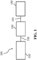
- FIG. 1 shows an engine exhaust system configuration used in gasoline engines according to one or more embodiments.
- FIG. 1 shows an engine exhaust system 100 comprising an ammonia generating catalyst 120 downstream from a gasoline engine 110 via an exhaust conduit 115, and a SCR catalytic article 130 downstream from the ammonia generating catalyst 120 via an exhaust conduit 125.
- the performance of the downstream SCR catalytic article 130 depends on the ammonia formation efficiency of the upstream ammonia generating catalyst 120.
- an exhaust gas system for treatment of a gasoline engine exhaust gas stream comprising: an ammonia generating catalyst comprising a NO x storage component, a refractory metal oxide support, a platinum component, and a palladium component, wherein the platinum component and the palladium component are present in a platinum to palladium ratio of greater than 1 to 1, and wherein the ammonia generating catalyst is substantially free of ceria; and an ammonia selective catalytic reduction (SCR) catalyst downstream of the ammonia generating catalyst.
- SCR selective catalytic reduction
- catalyst or “catalyst material” or “catalytic material” refer to a material that promotes a reaction.
- a catalytic article refers to an element that is used to promote a desired reaction.
- a catalytic article may comprise a washcoat containing a catalytic species, e.g., a catalyst composition, on a substrate, e.g., a honeycomb substrate.
- the terms “layer” and “layered” refer to a structure that is supported on a surface, e.g. a substrate.
- gasoline engine refers to any internal combustion engine with spark-ignition designed to run on gasoline.
- the engine is a lean gasoline direct injection engine.
- Gasoline direct injection (GDI) engines can have lean burn conditions and stratified combustion resulting in the generation of particulates. In contrast to particulates generated by diesel lean burn engines, the particulates generated by GDI engines tend to be finer and in lesser quantities.
- washcoat has its usual meaning in the art of a thin, adherent coating of a catalytic or other material applied to a carrier substrate material, such as a honeycomb-type carrier member, which is sufficiently porous to permit the passage of the gas stream being treated.
- a washcoat is obtained from a dispersion of particles in slurry, which is applied to a substrate, dried and calcined to provide the porous washcoat.
- gas stream broadly refers to any combination of flowing gas that may contain solid or liquid particulate matter.
- gaseous stream or “exhaust gas stream” means a stream of gaseous constituents, such as the exhaust of an engine, which may contain entrained non-gaseous components such as liquid droplets, solid particulates, and the like.
- the exhaust gas stream of an engine typically further comprises combustion products, products of incomplete combustion, oxides of nitrogen, combustible and/or carbonaceous particulate matter (soot), and un-reacted oxygen and nitrogen.
- the ammonia generating catalyst comprises a NO x storage component, a refractory metal oxide support, a platinum component, and a palladium component, wherein the platinum component and the palladium components are present in a platinum to palladium ratio of greater than 1 to 1, and wherein the ammonia generating catalyst is substantially free of ceria.
- the NO x storage (sorbent) component includes one or more alkaline earth metal oxides or carbonates, such as oxides or carbonates of Mg, Ca, Sr, and Ba, and alkali metal oxides or carbonates such as oxides or carbonates of Li, Na, K, Rb, and Cs.
- the NO x storage component is selected from an oxide or carbonate of one or more of cesium, barium, magnesium, calcium, and strontium.
- barium oxide is usually preferred because it forms nitrates at lean engine operation and releases the nitrates relatively easily under rich conditions.
- the NO x storage component is selected from an oxide or carbonate of barium.
- the NO x storage component is present in an amount in the range of about 5 to about 30 wt. %, including about 5 to about 25 wt. %, about 5 to about 20 wt. %, about 10 to about 25 wt. %, about 10 to about 20 wt. %, about 15 to about 25 wt. %, about 15 to about 20 wt. %, and about 20 to about 25 wt. %, on an oxide basis, based on the total weight of the ammonia generating catalyst.
- the NO x storage component comprises an oxide or carbonate of barium, and the barium is present in an amount in the range of about 5 to about 30 wt. %, including about 5 to about 25 wt. %, about 5 to about 20 wt. %, about 10 to about 25 wt. %, about 10 to about 20 wt. %, about 15 to about 25 wt. %, about 15 to about 20 wt. %, and about 20 to about 25 wt.%, on an oxide basis, based on the total weight of the ammonia generating catalyst.
- refractory metal oxide support and “support” refer to the underlying high surface area material upon which additional chemical compounds or elements are carried.
- the support particles have pores larger than 20 ⁇ and a wide pore distribution.
- such supports e.g., metal oxide supports, exclude molecular sieves, specifically, zeolites.
- high surface area refractory metal oxide supports can be utilized, e.g., alumina support materials, also referred to as “gamma alumina” or “activated alumina,” which typically exhibit a BET surface area in excess of 60 square meters per gram (“m2/g”), often up to about 200 m2/g or higher.
- Such activated alumina is usually a mixture of the gamma and delta phases of alumina, but may also contain substantial amounts of eta, kappa, and theta alumina phases.
- Refractory metal oxides other than activated alumina can be used as a support for at least some of the catalytic components in a given catalyst. For example, bulk ceria, zirconia, alpha alumina, silica, titania, and other materials are known for such use.
- One or more embodiments of the present invention include a refractory metal oxide support comprising an activated compound selected from the group consisting of alumina, zirconia, alumina-zirconia, lanthana-alumina, lanthana-zirconia-alumina, baria-alumina, baria-lanthana-alumina, baria-lanthana-neodymia-alumina, alumina-chromia, and combinations thereof. Although many of these materials suffer from the disadvantage of having a considerably lower BET surface area than activated alumina, that disadvantage tends to be offset by a greater durability or performance enhancement of the resulting catalyst.
- BET surface area has its usual meaning of referring to the Brunauer, Emmett, Teller method for determining surface area by N 2 adsorption. Pore diameter and pore volume can also be determined using BET-type N 2 adsorption or desorption experiments.
- the refractory metal oxide supports independently comprise a compound that is activated, stabilized, or both, selected from the group consisting of alumina, zirconia, alumina-zirconia, lanthana-alumina, lanthana-zirconia-alumina, baria-alumina, baria-lanthana-alumina, baria-lanthana-neodymia-alumina, alumina-chromia, and combinations thereof. It is noted that when the refractory metal oxide support is stabilized with ceria, the ceria stabilizer is present in an amount less than 1 wt.%, based on the weight of the ammonia generating catalyst.
- the refractory metal oxide support comprises less than 1 wt.% of a ceria stabilizer, including less than 0.75 wt.%, less than 0.5 wt.%, less than 0.25 wt. %, and less than 0.1 wt. %. In one or more specific embodiments, the refractory metal oxide support comprises alumina.
- oxygen storage component refers to an entity that has a multivalence state and can actively react with reductants such as carbon monoxide (CO) or hydrogen under reduction conditions and then react with oxidants such as oxygen or nitrous oxides under oxidative conditions.
- reductants such as carbon monoxide (CO) or hydrogen under reduction conditions
- oxidants such as oxygen or nitrous oxides under oxidative conditions.
- oxygen storage components include rare earth oxides, particularly ceria, lanthana, praseodymia, neodymia, niobia, europia, samaria, ytterbia, yttria, zirconia, and mixtures thereof in addition to ceria.
- the ammonia generating catalyst is substantially free of ceria.
- substantially free of ceria means that there is generally less than about 1 wt. %, including less than about 0.75 wt.%, less than about 0.5 wt. %, less than about 0.25 wt. %, or less than about 0.1 wt. %, of ceria in the ammonia generating catalyst. In some embodiments, no ceria has been intentionally added to the ammonia generating catalyst.
- trace amounts of ceria may migrate from one washcoat component to another, such that trace amounts of ceria can be present in the ammonia generating catalyst.
- substantially free of ceria includes “free of ceria.”
- the term "platinum group metal” or “PGM” refers to one or more chemical elements defined in the Periodic Table of Elements, including platinum (Pt), palladium, rhodium, osmium, iridium, and ruthenium, and mixtures thereof.
- the ammonia generating catalyst comprises a platinum component and a palladium component supported on the refractory metal oxide support. Generally, there are no specific restrictions as far as the palladium and platinum content of the ammonia generating catalyst is concerned.
- the platinum loading is in the range of about 1 g/ft 3 to about 300 g/ft 3 , including about 10m g/ft 3 to about 300 g/ft 3 , and about 10 g/ft 3 to about 100 g/ft 3
- the palladium loading is in the range of 0 g/ft 3 to about 150 g/ft 3 , including about 1 g/ft 3 to about 100 g/ft 3 , and 0 to about 30 g/ft 3 .
- platinum group metal component refers to the respective platinum group metal compound, complex, or the like which, upon calcination or use of the catalyst decomposes or otherwise converts to a catalytically active form, usually, the metal or the metal oxide.
- the platinum component and palladium component are present in a platinum to palladium ratio of greater than 1 to 1. In some embodiments, there is no palladium present. As will be appreciated by one skilled in the art, the platinum and/or palladium can be in an alloy form.
- the Pt/Pd ratio is in the range of about 2/1 to about 100/1, including the ranges of about 2/1 to about 50/1, about 2/1 to about 25/1, about 2/1 to about 20/1, 3/1 to 100/1, 3/1 to 50/1, about 3/1 to about 25/1, about 3/1 to 20/1, 4/1 to 100/1, 4/1 to 50/1, 4/1 to 25/1, about 4/1 to about 20/1, 5/1 to about 100/1, about 5/1 to about 50/1, about 5/1 to about 25/1, about 5/1 to 20/1, about 6/1 to about 100/1, about 6/1 to about 50/1, about 6/1 to about 25/1, about 7/1 to about 100/1, about 7/1 to about 50/1, about 7/1 to about 25/1, about 8/1 to about 100/1, about 8/1 to about 50/1, about 8/1 to about 25/1, about 9/1 to about 100/1, about 9/1 to about 50/1, about 9/1 to about 25/1, about 10/1 to about 100/1, about 10/1 to about 50/1, and about 10/1, 5/1 to about 50
- the ammonia generating catalyst is upstream of a selective-catalytic reduction (SCR) catalyst.
- SCR selective-catalytic reduction
- upstream and downstream refer to relative directions according to the flow of an engine exhaust gas stream from an engine towards a tailpipe, with the engine in an upstream location and the tailpipe and any pollution abatement articles such as filters and catalysts being downstream from the engine.
- a catalyst or catalyst zone is “downstream” or “upstream” from another catalyst or zone, it may be on a different substrate or brick or on a different region of the same substrate or brick.
- the ammonia generating catalyst is immediately upstream of the SCR catalyst.
- the term "immediately upstream” refers to the relative direction according to the flow of an engine exhaust gas stream from an engine towards a tailpipe and means that there is no other catalytic material between the ammonia generating catalyst and the SCR catalyst.
- SCR selective catalytic reduction
- nitrogen oxides and “NO x” designate the oxides of nitrogen.
- the SCR catalyst can be a mixed oxide, a molecular sieve or combinations thereof.
- the term "mixed oxide” refers to an oxide that contains cations of more than one chemical element or cations of a single element in several states of oxidation.
- the mixed oxide is selected from Fe/titania (e.g. FeTiO 3 ), Fe/alumina (e.g. FeAl 2 O 3 ), Mg/titania (e.g. MgTiO 3 ), Mg/alumina (e.g. MgAl 2 O 3 ), Mn/alumina, Mn/titania (e.g. MnO x /TiO 2 ) (e.g.
- the mixed oxide comprises vanadia/titania.
- the vanadia/titania oxide can be activated or stabilized with tungsten (e.g., WO 3 ) to provide V 2 O 5 /TiO 2 /WO 3 .
- molecular sieve refers to framework materials such as zeolites and other framework materials (e.g., isomorphously substituted materials), which may in particulate form in combination with one or more promoter metals be used as catalysts.
- Molecular sieves are materials based on an extensive three-dimensional network of oxygen ions containing generally tetrahedral type sites and having a substantially uniform pore distribution, with the average pore size being no larger than 20 ⁇ . The pore sizes are defined by the ring size.
- zeolite refers to a specific example of a molecular sieve, including silicon and aluminum atoms.
- the molecular sieves by their framework type, it is intended to include the framework type and any and all isotypic framework materials such as SAPO, ALPO and MeAPO materials having the same framework type as the zeolite materials.
- aluminosilicate zeolite excludes aluminophosphate materials such as SAPO, ALPO, and MeAPO materials, and the broader term "zeolite” is intended to include aluminosilicates and aluminophosphates.
- Zeolites are crystalline materials having rather uniform pore sizes which, depending upon the type of zeolite and the type and amount of cations included in the zeolite lattice, range from about 3 to about 10 Angstroms in diameter. Zeolites generally comprise silica to alumina (SAR) molar ratios of 2 or greater.
- aluminophosphates refers to another specific example of a molecular sieve, including aluminum and phosphate atoms. Aluminophosphates are crystalline materials having rather uniform pore sizes.
- molecular sieves e.g., zeolites
- zeolites are defined as aluminosilicates with open 3-dimensional framework structures composed of corner-sharing TO 4 tetrahedra, where T is Al or Si, or optionally P.
- Cations that balance the charge of the anionic framework are loosely associated with the framework oxygens, and the remaining pore volume is filled with water molecules.
- the non-framework cations are generally exchangeable, and the water molecules removable.
- the molecular sieve materials independently, comprise SiO 4 /AlO 4 tetrahedra and are linked by common oxygen atoms to form a three-dimensional network. In other embodiments, the molecular sieve materials comprise SiO 4 /AlO 4 /PO 4 tetrahedra.
- the molecular sieve materials of one or more embodiments can be differentiated mainly according to the geometry of the voids which are formed by the rigid network of the (SiO 4 )/AlO 4 , or SiO 4 /AlO 4 /PO 4 , tetrahedra.
- the entrances to the voids are formed from 6, 8, 10, or 12 ring atoms with respect to the atoms which form the entrance opening. In one or more embodiments, the molecular sieve materials comprise ring sizes of no larger than 12, including 6, 8, 10, and 12.
- the molecular sieve materials can be based on the framework topology by which the structures are identified.
- any framework type of zeolite can be used, such as framework types of ABW, ACO, AEI, AEL, AEN, AET, AFG, AFI, AFN, AFO, AFR, AFS, AFT, AFX, AFY, AHT, ANA, APC, APD, AST, ASV, ATN, ATO, ATS, ATT, ATV, AWO, AWW, BCT, BEA, BEC, BIK, BOG, BPH, BRE, CAN, CAS, SCO, CFI, SGF, CGS, CHA, CHI, CLO, CON, CZP, DAC, DDR, DFO, DFT, DOH, DON, EAB, EDI, EMT, EON, EPI, ERI, ESV, ETR, EUO, FAU, FER, FRA, GIS, GIU
- the molecular sieve materials comprise an 8-ring small pore aluminosilicate zeolite.
- small pore refers to pore openings, which are smaller than about 5 Angstroms, for example on the order of -3.8 Angstroms.
- the phrase "8-ring" zeolites refers to zeolites having 8-ring pore openings and double-six ring secondary building units and having a cage like structure resulting from the connection of double six-ring building units by 4 rings.
- Zeolites are comprised of secondary building units (SBU) and composite building units (CBU), and appear in many different framework structures. Secondary building units contain up to 16 tetrahedral atoms and are non-chiral.
- Composite building units are not required to be achiral, and cannot necessarily be used to build the entire framework.
- a group of zeolites have a single 4-ring (s4r) composite building unit in their framework structure.
- the "4" denotes the positions of tetrahedral silicon and aluminum atoms, and the oxygen atoms are located in between tetrahedral atoms.
- Other composite building units include, for example, a single 6-ring (s6r) unit, a double 4-ring (d4r) unit, and a double 6-ring (d6r) unit.
- the d4r unit is created by joining two s4r units.
- the d6r unit is created by joining two s6r units.
- Zeolitic framework types that have a d6r secondary building unit include AEI, AFT, AFX, CHA, EAB, EMT, ERI, FAU, GME, JSR, KFI, LEV, LTL, LTN, MOZ, MSO, MWW, OFF, SAS, SAT, SAV, SBS, SBT, SFW, SSF, SZR, TSC, and WEN.
- the molecular sieve materials comprise a d6r unit.
- the molecular sieve materials have a framework type selected from AEI, AFT, AFX, CHA, EAB, EMT, ERI, FAU, GME, JSR, KFI, LEV, LTL, LTN, MOZ, MSO, MWW, OFF, SAS, SAT, SAV, SBS, SBT, SFW, SSF, SZR, TSC, WEN, and combinations thereof.
- the molecular sieve materials have a framework type selected from the group consisting of CHA, AEI, AFX, ERI, KFI, LEV, and combinations thereof.
- the molecular sieve materials have a framework type selected from CHA, AEI, and AFX.
- the molecular sieve materials have the CHA framework type.
- Zeolitic CHA-framework type molecular sieves includes a naturally occurring tectosilicate mineral of a zeolite group with approximate formula: (Ca,Na 2 ,K 2 ,Mg)Al 2 Si 4 O 12 ⁇ 6H 2 O (e.g., hydrated calcium aluminum silicate).
- Three synthetic forms of zeolitic CHA-framework type molecular sieves are described in " Zeolite Molecular Sieves," by D. W. Breck, published in 1973 by John Wiley & Sons , which is hereby incorporated by reference. The three synthetic forms reported by Breck are Zeolite K-G, described in J. Chem. Soc., p.
- the molecular sieve materials can include all aluminosilicate, borosilicate, gallosilicate, MeAPSO, and MeAPO compositions. These include, but are not limited to SSZ-13, SSZ-62, natural chabazite, zeolite K-G, Linde D, Linde R, LZ-218, LZ-235. LZ-236, ZK-14, SAPO-34, SAPO-44, SAPO-47, ZYT-6, CuSAPO-34, CuSAPO-44, and CuSAPO-47.
- the ratio of silica to alumina of an aluminosilicate molecular sieve component can vary over a wide range.
- the molecular sieve materials have a silica to alumina molar ratio (SAR) in the range of 2 to 300, including 5 to 250; 5 to 200; 5 to 100; and 5 to 50.
- the molecular sieve materials have a silica to alumina molar ratio (SAR) in the range of 10 to 200, 10 to 100, 10 to 75, 10 to 60, and 10 to 50; 15 to 100, 15 to 75, 15 to 60, and 15 to 50; 20 to 100, 20 to 75, 20 to 60, and 20 to 50.
- the term "promoted” refers to a component that is intentionally added to the molecular sieve material, as opposed to impurities inherent in the molecular sieve.
- a promoter is intentionally added to enhance activity of a catalyst compared to a catalyst that does not have promoter intentionally added.
- suitable metal(s) is independently exchanged into the molecular sieve.
- the molecular sieve is promoted with one or more of copper (Cu), iron (Fe), cobalt (Co), nickel (Ni), lanthanum (La), cerium (Ce), manganese (Mn), vanadium (V), or silver (Ag).
- the molecular sieve is promoted with one or more of copper (Cu) or iron (Fe).
- the molecular sieve is promoted with Cu.
- the promoter metal content of the catalyst, calculated as the oxide is, in one or more embodiments, at least about 0.1 wt. %, reported on a volatile-free basis.
- the promoter metal content, calculated as the oxide is in the range of 0.1 wt. % up to about 10 wt. %, including 9, 8, 7, 6, 5, 4, 3, 2, 1, 0.5, 0.25, and 0.1 wt. %, in each case based on the total weight of the calcined molecular sieve reported on a volatile free basis.
- the promoter metal comprises Cu
- the Cu content, calculated as CuO is in the range of 0.1 wt. % up to about 5 wt. %, including about 5, about 4, about 3, about 2, about 1, about 0.5, about 0.25, and about 0.1 wt. %, in each case based on the total weight of the calcined molecular sieve reported on a volatile free basis.
- the Cu content of the molecular sieve, calculated as CuO is in the range of about 2 to about 5 wt.%.
- the exhaust gas treatment system further comprises an ammonia oxidation (AMOx) catalyst downstream of the SCR catalyst.
- the ammonia oxidation catalyst may be provided downstream of the SCR catalyst to remove any slipped ammonia from upstream components of the exhaust gas treatment system.
- the SCR catalyst is on a substrate having an inlet and an outlet, and includes an ammonia oxidation (AMOx) catalyst at the outlet.
- the AMOx catalyst may comprise a platinum group metal such as platinum, palladium, rhodium, or combinations thereof.
- the AMOx catalyst may comprise a bottom coat with one or more PGM components and a top coat with SCR functionality.
- Such AMOx catalysts are useful in exhaust gas treatment systems including an SCR catalyst.
- a gaseous stream containing oxygen, nitrogen oxides, and ammonia can be sequentially passed through first and second catalysts, the first catalyst favoring reduction of nitrogen oxides and the second catalyst favoring the oxidation or other decomposition of excess ammonia.
- the first catalyst can be the SCR catalyst
- the second catalyst can be an AMOx catalyst and/or SCR+AMOx integrated catalyst, optionally comprising a zeolite.
- AMOx catalyst composition(s) can be coated on a flow through substrate or wall-flow filter substrate. If a wall flow filter substrate is utilized, the resulting system will be able to remove particulate matter along with gaseous pollutants.
- the wall-flow filter substrate can be made from materials commonly known in the art, such as cordierite, aluminum titanate or silicon carbide. It will be understood that the loading of the catalytic composition on a wall flow filter substrate will depend on substrate properties such as porosity and wall thickness, and typically will be lower than loading on a flow through substrate.
- Substrate In one or more embodiments, the ammonia generating catalyst and the SCR catalyst are located on separate substrates.
- the term "substrate” refers to the monolithic material onto which the catalyst material is placed, typically in the form of a washcoat.
- a washcoat is formed by preparing a slurry containing a specified solids content (e.g., 30-90% by weight) of catalyst in a liquid, which is then coated onto a substrate and dried to provide a washcoat layer.
- washcoat has its usual meaning in the art of a thin, adherent coating of a catalytic or other material applied to a substrate material, such as a honeycomb-type carrier member, which is sufficiently porous to permit the passage of the gas stream being treated.
- the substrate is selected from one or more of a flow-through honeycomb monolith, or a particulate filter, and the catalytic material(s) are applied to the substrate as a washcoat.
- the substrate is a ceramic or metal substrate having a honeycomb structure.
- Any suitable substrate may be employed, such as a monolithic substrate of the type having fine, parallel gas flow passages extending therethrough from an inlet or an outlet face of the substrate such that passages are open to fluid flow therethrough.
- the passages which are essentially straight paths from their fluid inlet to their fluid outlet, are defined by walls on which the catalytic material is coated as a washcoat so that the gases flowing through the passages contact the catalytic material.
- the flow passages of the monolithic substrate are thin-walled channels, which can be of any suitable cross-sectional shape and size such as trapezoidal, rectangular, square, sinusoidal, hexagonal, oval, circular, etc.
- Such structures may contain from about 60 to about 900 or more gas inlet openings (i.e. cells) per square inch of cross section.
- a metallic substrate may include any metallic substrate, such as those with openings or "punch-outs" in the channel walls.
- a ceramic substrate may be made of any suitable refractory material, e.g., cordierite, cordierite- ⁇ -alumina, silicon nitride, zircon mullite, spodumene, alumina-silica-magnesia, zircon silicate, sillimanite, a magnesium silicate, zircon, petalite, ⁇ -alumina, an aluminosilicate and the like.
- the substrates useful for the catalyst materials of embodiments of the present invention may also be metallic in nature and be composed of one or more metals or metal alloys.
- the metallic substrates may be employed in various shapes such as pellets, corrugated sheet or monolithic form.
- Specific examples of metallic substrates include the heat-resistant, base-metal alloys, especially those in which iron is a substantial or major component.
- Such alloys may contain one or more of nickel, chromium, and aluminum, and the total of these metals may advantageously comprise at least about 15 wt. % of the alloy, for instance, about 10 to about 25 wt. % chromium, about 1 to about 8 wt. % of aluminum, and 0 to about 20 wt. % of nickel.
- the particulate filter can be selected from a gasoline particulate filter or a soot filter.
- Particulate filter or “soot filter” refer to a filter designed to remove particulate matter from an exhaust gas stream such as soot.
- Particulate filters include, but are not limited to honeycomb wall flow filters, partial filtration filter, a wire mesh filter, wound fiber filters, sintered metal filters, and foam filters.
- the particulate filter is a catalyzed soot filter (CSF).
- CSF catalyzed soot filter
- the catalyzed CSF comprises a substrate coated with a washcoat layer containing a platinum group metal for burning off trapped soot and/or oxidizing NO to NO 2 .
- the catalyzed CSF is coated with a platinum group metal and one or more high surface area refractory metal oxide supports (e.g., alumina, silica, silica alumina, zirconia, zirconia alumina, and ceria-zirconia) for the combustion of unburned hydrocarbons and, to some degree, particulate matter.
- alumina, silica, silica alumina, zirconia, zirconia alumina, and ceria-zirconia e.g., alumina, silica, silica alumina, zirconia, zirconia alumina, and
- Wall flow substrates useful for supporting the catalyst material of one or more embodiments have a plurality of fine, substantially parallel gas flow passages extending along the longitudinal axis of the substrate. Typically, each passage is blocked at one end of the substrate body, with alternate passages blocked at opposite end-faces.
- Such monolithic substrates may contain up to about 900 or more flow passages (or "cells") per square inch of cross section, although far fewer may be used.
- the substrate may have from about 7 to 600, more usually from about 100 to 400, cells per square inch (“cpsi").
- the porous wall flow filter used in embodiments of the invention can be catalyzed in that the wall of said element has thereon or contained therein a platinum group metal.
- Catalytic materials may be present on the inlet side of the element wall alone, the outlet side alone, both the inlet and outlet sides, or the wall itself may consist all, or in part, of the catalytic material.
- this invention may include the use of one or more washcoat layers of catalytic materials and combinations of one or more washcoat layers of catalytic materials on the inlet and/or outlet walls of the element.
- FIG. 2 illustrates a wall flow filter substrate 50 which has a plurality of passages 52.
- the passages are tubularly enclosed by the channel walls 53 of the filter substrate.
- the substrate has an inlet end 54 and an outlet end 56. Alternate passages are plugged at the inlet end with inlet plugs 58, and at the outlet end with outlet plugs 60 to form opposing checkerboard patterns at the inlet end 54 and outlet end 56.
- a gas stream 62 enters through the unplugged channel inlet 64, is stopped by outlet plug 60 and diffuses through channel walls 53 (which are porous) to the outlet side 66. The gas cannot pass back to the inlet side of walls because of inlet plugs 58.
- the ammonia generating catalyst and the SCR catalyst are located on separate substrates.
- the ammonia generating catalyst can be located on a flow through substrate and the SCR catalyst can be located on a separate flow through substrate; the ammonia generating catalyst can be located on a flow through substrate; and the SCR catalyst can be located on a wall flow filter (i.e., SCR on a filter); or the ammonia generating catalyst can be located on a particulate filter and the SCR catalyst can be located on a flow through substrate.
- the SCR catalyst is disposed on a wall-flow filter. In other embodiments, the SCR catalyst is disposed on a flow-through substrate.
- Embodiments where the ammonia generating catalyst and the SCR catalyst are on separate substrates are more specifically illustrated in FIG. 3 .
- part of the exhaust gas treatment system 300 shown is an axially zoned arrangement where the ammonia generating catalyst 320 is located upstream of the SCR catalyst 330 and these catalysts are on separate substrates, a first substrate 305 and a second substrate 315.
- the ammonia generating catalyst 320 is disposed on a first substrate 305
- the SCR catalyst 330 is disposed on a separate second substrate 315.
- the first and second substrates 305 and 315 can be comprised of the same material or a different material.
- the first substrate 305 has an inlet end 325 and an outlet end 335 defining an axial length L1.
- the second substrate 315 has an inlet end 326 and an outlet end 336 defining an axial length L2.
- the first and second substrates 305 and 315 generally comprise a plurality of channels 350 of a honeycomb substrate, of which only one channel is shown in cross-section for clarity.
- the ammonia generating catalyst 320 extends from the inlet end 325 of the first substrate 305 through the entire axial length L1 of the first substrate 305 to the outlet end 335.
- the length of the ammonia generating catalyst 320 is denoted as first zone length 305a in FIG. 3 .
- the SCR catalyst 330 extends from the outlet end 336 of the second substrate 315 through the entire axial length L2 of the second substrate 315 to the inlet end 326.
- the SCR catalyst 330 defines a second zone length 315a in FIG. 3 . It will be appreciated that the lengths of substrate 305a and the length of substrate 315a can be varied.
- the ammonia generating and SCR catalyst can be located on a single substrate.
- the designs can include zoned and layered systems.
- the ammonia generating catalyst and the SCR catalyst are on single substrate in a layered relationship
- the ammonia generating catalyst can be coated on a substrate to form a first layer (or bottom coat), and the SCR catalyst is washcoated on top of the first layer to form a second layer (or top coat).
- the top coat/second layer of the SCR catalyst is downstream of the bottom coat/first layer of the ammonia generating catalyst.
- the ammonia generating catalyst and the SCR catalyst are arranged in an axially zoned configuration on a single substrate.
- axially zoned refers to the location of the upstream zone and downstream zone relative to one another. Axially means side-by-side such that the upstream zone and the downstream zone are located one beside the other.
- FIG. 4 an exemplary embodiment of an axially zoned system 400 is shown.
- the ammonia generating catalyst 420 is located upstream of the SCR catalyst 430 on a common substrate 405.
- the substrate 405 has an inlet end 425 and an outlet end 435 defining an axial length L.
- the substrate 405 generally comprises a plurality of channels 450 of a honeycomb substrate, of which only one channel is shown in cross-section for clarity.
- the ammonia generating catalyst 420 extends from the inlet end 425 of the substrate 405 through less than the entire axial length L of the substrate 405.
- the length of the ammonia generating catalyst 420 is denoted as first zone length 420a in FIG. 4 .
- the SCR catalyst 430 extends from the outlet end 435 of the substrate 405 through less than the entire axial length L of the substrate 405.
- the length of the SCR catalyst 430 is denoted as the second zone length 430a in FIG. 4 .
- the ammonia generating catalyst 420 is directly abutting the SCR catalyst 430. In still further embodiments, there may be a gap between the ammonia generating catalyst 420 and the SCR catalyst 430 (not illustrated). It will be appreciated by one skilled in the art that the ammonia generating catalyst 420 and SCR catalyst 430 can be at least partially overlapping (not illustrated). In one or more embodiments the ammonia generating catalyst 420 is at least partially overlapping the SCR catalyst 430. In other embodiments, the SCR catalyst 430 is at least partially overlapping the ammonia generating catalyst 420.
- the ammonia generating catalyst and the SCR catalyst are on a single substrate, which comprises a wall flow filter.
- the ammonia generating catalyst is coated on the inlet passages of the wall flow filter, and the SCR catalyst is coated on the outlet passages of the wall flow filter.
- the engine exhaust system of one or more embodiments can further comprise a three-way conversion (TWC) catalyst upstream or downstream from the ammonia generating catalyst. Additionally, in one or more embodiments, the engine exhaust system can further comprises an ammonia oxidation catalyst disposed downstream of the SCR catalyst to address any slipped ammonia.
- FIG. 5 shows an engine exhaust system 500 comprising an ammonia generating catalyst 530 downstream from a gasoline engine 510 via an exhaust conduit 515, an optional TWC catalyst 540 downstream from the ammonia generating catalyst 530 via an exhaust conduit 535, and a SCR catalytic article 550 downstream from the ammonia generating catalyst 530 and the optional TWC catalyst 540 via an exhaust conduit 545.
- the exhaust gas system 500 further comprises an optional ammonia oxidation catalyst 560 disposed downstream of the SCR catalyst 550 via an exhaust conduit 555.
- the gasoline engine exhaust system 500 comprises an ammonia generating catalyst 530 downstream from a gasoline engine 510 via an exhaust conduit 515, an optional TWC catalyst 520 upstream from the ammonia generating catalyst 530 via an exhaust conduit 525, and a SCR catalytic article 550 downstream from the ammonia generating catalyst 530 and the optional TWC catalyst 520 via an exhaust conduit 545.
- the exhaust gas system 500 further comprises an optional ammonia oxidation catalyst 560 disposed downstream of the SCR catalyst 550 via an exhaust conduit 555.
- one or more of the ammonia generating catalyst 530, the SCR catalyst 550, or either of the optional TWC catalysts 520 and 540 can be on a filter.
- the engine exhaust gas treatment system of one or more embodiments can further comprises a wall flow filter disposed upstream of the SCR catalyst.
- FIG. 6 shows an engine exhaust system 600 comprising an ammonia generating catalyst 620 downstream from a gasoline engine 610 via an exhaust conduit 615, an optional wall flow filter 630 upstream from the ammonia generating catalyst 620 via an optional exhaust conduit 625, and a SCR catalytic article 640 downstream from the ammonia generating catalyst 620 via an exhaust conduit 635.
- the wall flow filter 630 has a three-way conversion (TWC) catalyst disposed thereon.
- the wall flow filter 630 has a TWC catalyst disposed thereon, as well as the ammonia generating catalyst disposed thereon.
- the optional exhaust conduit 625 is absent from the engine exhaust system 600.
- Table 1 presents various system configurations of one or more embodiments. It is noted that each component is connected to the next component via exhaust conduits such that the engine is upstream of component A, which is upstream of component B, which is upstream of component C, which is upstream of component D.
- Table 1 System Configurations Component A Component B Component C Component D Ammonia generating catalyst TWC SCR Optional AMOx Ammonia generating catalyst TWC SCR on a filter Optional AMOx Ammonia generating catalyst on a filter TWC SCR Optional AMOx TWC Ammonia generating catalyst SCR Optional AMOx TWC Ammonia generating catalyst on a filter SCR Optional AMOx TWC Ammonia generating catalyst SCR on a filter Optional AMOx TWC Ammonia generating catalyst SCR Optional AMOx Ammonia generating catalyst TWC on a filter SCR Optional AMOx Ammonia generating catalyst TWC on a filter SCR Optional AMOx Ammonia generating catalyst TWC on a filter SCR Optional AMOx Ammonia generating catalyst TWC on a filter SCR Optional AMOx
- a method for treatment of an engine exhaust gas stream of a gasoline engine comprises flowing the engine exhaust gas stream over an ammonia generating catalyst; and directing the exhaust gas stream containing ammonia through a SCR catalyst.
- Example 1 samples were measured by H 2 TPR. Prior to measurement, samples were treated at 450 °C in 4% O 2 /He for 20 min, and then cooled down to -50 °C in He (g). TPR was measured in the presence of 1% H 2 /N 2 with temperature ramping up from -50 to 700 °C at a rate of 10 °C/min. The volumes of H 2 consumed to reduce per gram of each sample were plotted in Figures 7A and 7B Each samples were measured after degreening at 750 °C for 2.5 hours ( Figure 7A ) and also after aging at 950 °C for 40 hours ( Figure 7B ), in 2% O 2 and 10% H 2 O balanced with N 2 .
- Volumes of H 2 consumed by the degreened Pd/Al 2 O 3 , Pt/Pd/Al 2 O 3 at 1/1 and 1/4 are similar to the calculated H 2 consumption volumes based on the assumption that all PdO is reduced to Pd. Volumes of H 2 consumed by the aged Pd/Al 2 O 3 and Pt/Pd/Al 2 O 3 at 1/4 are lower than the calculated values, but they are significantly higher than those of the Pt/Pd/Al 2 O 3 rich in Pt, and the H 2 consumption linearly increases with Pd loading increasing.
- the catalyst contains an activated ⁇ -alumina, barium carbonate, platinum, and palladium at concentrations of approximately 68%, 23%, 8%, and 0.8%, respectively, based on the calcined weight of the catalyst.
- Pd in the form of palladium nitrate and Pt in the form of platinum amine solution were introduced onto the BaCO 3 / ⁇ -Al 2 O 3 by conventional incipient wetness techniques.
- This catalyst was coated onto a flow-through monolith substrate carrier having a cell density of 900 cells per square inch (cpsi) and a 2.5 mil wall thickness.
- the total washcoat loading after 550 °C calcination for one hour in air was about 1.8 g/in 3 .
- This two layer formulation which comprises an undercoat washcoat layer and a top washcoat layer, was coated onto a flow-through monolith substrate carrier having a cell density of 400 cells per square inch (cpsi) and a 4 mil wall thickness, the top washcoat layer being coated over the undercoat washcoat layer.
- the catalyst has a total 180 g/ft 3 PGM nominal loading with a Pt/Pd ratio of 63/117.
- the first layer (undercoat washcoat layer) contains an activated ⁇ -alumina, cerium oxide, barium carbonate, magnesia, zirconia, platinum, and palladium at concentrations of approximately 55%, 23%, 10%, 7.1%, 3.5%, 1.1% and 0.12%, respectively, based on the calcined weight of the catalyst.
- the total washcoat loading of the first layer after 550 °C calcination for one hour in air was about 3.4 g/in 3 .
- the second layer (top washcoat layer) was disposed on the first layer.
- the second layer contains an activated ⁇ -alumina, OSC material (CeO 2 /ZrO 2 ) with promoters, barium carbonate, zirconia, palladium at concentrations of approximately 9.2%, 78%, 8.7%, 2.3%, 3%, respectively, based on the calcined weight of the catalyst.
- the second trap layer was coated over the entire first layer.
- the total washcoat of the second layer after 550 °C calcination was about 2.2 g/in 3 .
- Example 3 and Example 4 were evaluated after degreening the catalysts at 750 °C for 2.5 hours and after aging at 950 °C for 40 hours.
- the catalysts were evaluated on a reactor test rig with FTIR analytical apparatus. The evaluations were conducted with cycles of a 60 seconds lean gas exposure followed by a 60 seconds rich gas exposure.
- the feeding gases contained hydrocarbons, CO, CO 2 , H 2 O and N 2 . NO was only included in the lean gas feed.
- the rich gas lambda is 0.953.
- the temperature was 355 °C in lean operation and 450 °C in rich operation.
- Figures 8A and 8B present the NO x and NH 3 concentrations of Example 3 and Example 4 tested after 950 °C aging.
- Example 3 showed NO x storage in lean exposure, as evidenced by the decreased outlet NO x concentration relative to the inlet NO x concentration. After transition to rich gas, a sharp NH 3 peak up to 1150 ppm was observed. Because NO x was not fed in the rich gas, the formed NH 3 originated from the stored lean NO x .
- Example 4 showed even higher NO x storage than Example 3 in lean exposure. However, after transition to rich, only a very small amount of NH 3 formed (less than 100 ppm), and the NH 3 formation showed a significant delay.
- Example 3 and Example 4 were evaluated in the same condition as Example 5, except NO was also included in the rich gas feed.
- Figures 9A and 9B present the NO x and NH 3 concentrations of Example 3 and Example 4 tested after 950 °C aging.
- NH 3 concentrations are far above the rich feed NO x , indicating the catalyst efficiently converted the stored lean NO x and the rich NO x to NH 3 .
- NH 3 formation appeared soon after the lean to rich transition only with a short delay, because the catalyst did not contain OSC and the Pt/Pd ratio was 245/25.
- the NH 3 concentrations were below the rich feed NO x concentration.
- NH 3 formation appeared much latter after lean to rich transition, due to the reductant consumption by OSC and PdO.
- Various catalysts were prepared, comprising alumina, barium carbonate, platinum, and palladium at concentrations listed in Table 3, based on the calcined weight of the catalyst.
- Pd in the form of palladium nitrate and Pt in the form of platinum amine solution were introduced onto BaCO 3 / ⁇ -Al 2 O 3 by conventional incipient wetness techniques.
- This catalyst was coated onto a flow-through monolith substrate carrier having a cell density of 900 cells per square inch (cpsi) and a 2.5 mil wall thickness.
- the total washcoat loading after 550 °C calcination for one hour in air was about 1.7 g/in 3 .
- Table 3 Catalyst Compositions with Different BaO Loadings Sample ID BaCO 3 wt.% alumina wt.% Pt wt.% Pd wt.% 7A 12.1 83.4 4.1 0.4 7B 24.3 71.2 4.1 0.4 7C 32.2 63.3 4.1 0.4 7D 38.6 56.9 4.1 0.4
- FIGS. 10A and 10B present the NO x concentrations in lean operation and the NH 3 concentrations in rich operation of Example 7A to 7D tested after aging at 950 °C for 40 hours.
- Figure 10A shows the outlet NO x concentrations decrease with increased BaO loading from 10 to 25%, indicating that higher BaO loading provided higher NO x storage capacity. Further increasing the BaO loading to 30% did not show benefit.
- Figure 10B shows the NH 3 concentrations increase with increased BaO loading from 10 to 25%, indicating that the higher NO x storage capacity resulted from higher BaO loading increased NH 3 formation. Further increasing the BaO loading to 30% did not show benefit.
- the catalyst contains ceria, alumina, barium carbonate, platinum, and palladium at concentrations listed in Table 4, based on the calcined weight of the catalyst.
- Pd in the form of palladium nitrate and Pt in the form of platinum amine solution were introduced onto the BaCO 3 / ⁇ -Al 2 O 3 by conventional incipient wetness techniques.
- This catalyst was coated onto a flow-through monolith substrate carrier having a cell density of 900 cells per square inch (cpsi) and a 2.5 mil wall thickness.
- the total washcoat loading after 550 °C calcination for one hour in air was included in Table 4.
- Sample IDs 7B, 8A, 8B and 8C were tested in the same condition as described in EXAMPLE 6, to demonstrate the negative impact of ceria on NH 3 formation activity.
- Figure 11 presents the outlet NH 3 concentrations of these catalysts, tested after aging at 950 °C for 40 hours.
- Sample ID 8A which contains 1% of ceria, did not delay the NH 3 formation, as compared to Sample ID 7B which is substantially free of ceria.
Landscapes
- Chemical & Material Sciences (AREA)
- Engineering & Computer Science (AREA)
- Chemical Kinetics & Catalysis (AREA)
- Combustion & Propulsion (AREA)
- Health & Medical Sciences (AREA)
- Mechanical Engineering (AREA)
- General Engineering & Computer Science (AREA)
- Toxicology (AREA)
- Analytical Chemistry (AREA)
- Organic Chemistry (AREA)
- Materials Engineering (AREA)
- Biomedical Technology (AREA)
- Environmental & Geological Engineering (AREA)
- General Chemical & Material Sciences (AREA)
- Oil, Petroleum & Natural Gas (AREA)
- Inorganic Chemistry (AREA)
- Catalysts (AREA)
- Exhaust Gas Treatment By Means Of Catalyst (AREA)
- Exhaust Gas After Treatment (AREA)
Claims (15)
- Système de traitement de gaz d'échappement comprenant :un catalyseur de génération d'ammoniac comprenant un composant de stockage de NOx, un support d'oxyde métallique réfractaire, un composant de platine, et un composant de palladium, le composant de platine et les composants de palladium étant présents selon un rapport de platine sur palladium supérieur à 1 sur 1, et le catalyseur de génération d'ammoniac contenant moins de 1 % en poids d'oxyde de cérium ; etun catalyseur de réduction catalytique sélective (SCR) d'ammoniac situé en aval du catalyseur de génération d'ammoniac.
- Système de traitement de gaz d'échappement selon la revendication 1, le composant de stockage de NOx étant choisi parmi un oxyde et un carbonate d'un métal alcalin ou alcalinoterreux, préférablement le composant de stockage de NOx étant choisi parmi un oxyde et un carbonate d'un ou plusieurs métaux choisis parmi le césium, le baryum, le magnésium, la calcium et le strontium, plus préférablement le composant de stockage de NOx étant choisi parmi un oxyde et un carbonate de baryum présent en une quantité dans une plage de 5 % à 30 % en poids sur une base d'oxyde, sur la base du poids total du catalyseur de génération d'ammoniac.
- Système de traitement de gaz d'échappement selon la revendication 1, le support d'oxyde métallique réfractaire étant choisi parmi l'alumine, la silice, l'oxyde de titane, l'oxyde de zirconium et des combinaisons correspondantes.
- Système de traitement de gaz d'échappement selon la revendication 1, le rapport Pt/Pd se situant dans la plage de 2/1 à 100/1, préférablement le rapport Pt/Pd se situant dans la plage de 4/1 à 20/1.
- Système de traitement de gaz d'échappement selon la revendication 1, le catalyseur de génération d'ammoniac et le catalyseur SCR se trouvant sur des substrats distincts, ou le catalyseur de génération d'ammoniac et le catalyseur SCR se trouvant sur un seul substrat, préférablement le substrat comprenant un filtre à écoulement sur les parois possédant des passages d'entrée et des passages de sortie, et le catalyseur de génération d'ammoniac se trouvant sur les passages d'entrée et le catalyseur SCR se trouvant sur les passages de sortie.
- Système de traitement de gaz d'échappement selon la revendication 1, le catalyseur de génération d'ammoniac comprenant du baryum, de l'alumine, du platine et du palladium.
- Système de traitement de gaz d'échappement selon la revendication 1, le catalyseur SCR comprenant un ou plusieurs parmi un matériau de tamis moléculaire, et un oxyde mixte, préférablement le matériau de tamis moléculaire possédant une unité à double cycle à six chaînons (d6r), plus préférablement le matériau de tamis moléculaire étant choisi parmi des types de structure AEI, CHA, et AFX, plus préférablement le matériau de tamis moléculaire possédant le type de structure CHA.
- Système de traitement de gaz d'échappement selon la revendication 7, le matériau de tamis moléculaire possédant un rapport silice sur alumine dans la plage de 2 à 100.
- Système de traitement de gaz d'échappement selon la revendication 7, le matériau de tamis moléculaire étant promu avec un métal choisi parmi Cu, Fe, Co, Ni, La, Ce, Mn, V, Ag, et des combinaisons correspondantes.
- Système de traitement de gaz d'échappement selon la revendication 1, le catalyseur SCR étant disposé sur un filtre à écoulement sur les parois, ou le catalyseur SCR étant disposé sur un substrat à écoulement traversant.
- Système de traitement de gaz d'échappement selon la revendication 1, un filtre à écoulement sur les parois étant disposé en amont du catalyseur SCR, le filtre possédant un catalyseur de conversion à trois voies (TWC) et le catalyseur de génération d'ammoniac sur celui-ci.
- Système de traitement de gaz d'échappement selon la revendication 1, comprenant en outre un catalyseur de conversion à trois voies (TWC), préférablement le catalyseur TWC se trouvant en amont du catalyseur de génération d'ammoniac, plus préférablement le catalyseur TWC comprenant un catalyseur TWC sur un filtre, ou le catalyseur TWC se trouvant en aval du catalyseur de génération d'ammoniac.
- Système de traitement de gaz d'échappement selon la revendication 1, comprenant en outre un catalyseur d'oxydation d'ammoniac en aval du catalyseur SCR.
- Système de traitement de gaz d'échappement selon la revendication 1, le composant de platine et les composants de palladium étant présents selon un rapport de platine sur palladium supérieur à 2 sur 1 ; et le catalyseur de réduction catalytique sélective (SCR) d'ammoniac comprenant un matériau de tamis moléculaire possédant une unité à double cycle à six chaînons (d6r).
- Procédé de traitement d'un flux de gaz d'échappement de moteur d'un moteur à essence, le procédé comprenant l'écoulement du flux de gaz d'échappement de moteur sur un catalyseur de génération d'ammoniac ; et la conduite du flux de gaz d'échappement à travers un catalyseur SCR situé en aval, le catalyseur de génération d'ammoniac contenant moins de 1 % en poids d'oxyde de cérium et le catalyseur de génération d'ammoniac comprenant un composant de stockage de NOx, un support d'oxyde métallique réfractaire, un composant de platine, et un composant de palladium, le composant de platine et le composant de palladium étant présents selon un rapport de platine sur palladium supérieur à 1 sur 1.
Priority Applications (1)
| Application Number | Priority Date | Filing Date | Title |
|---|---|---|---|
| PL16808420T PL3307997T3 (pl) | 2015-06-12 | 2016-06-10 | Układ oczyszczania gazów spalinowych |
Applications Claiming Priority (2)
| Application Number | Priority Date | Filing Date | Title |
|---|---|---|---|
| US201562174856P | 2015-06-12 | 2015-06-12 | |
| PCT/US2016/036980 WO2016201295A1 (fr) | 2015-06-12 | 2016-06-10 | Système de traitement de gaz d'échappement |
Publications (3)
| Publication Number | Publication Date |
|---|---|
| EP3307997A1 EP3307997A1 (fr) | 2018-04-18 |
| EP3307997A4 EP3307997A4 (fr) | 2018-12-05 |
| EP3307997B1 true EP3307997B1 (fr) | 2020-03-18 |
Family
ID=57504428
Family Applications (1)
| Application Number | Title | Priority Date | Filing Date |
|---|---|---|---|
| EP16808420.0A Active EP3307997B1 (fr) | 2015-06-12 | 2016-06-10 | Système de traitement de gaz d'échappement |
Country Status (12)
| Country | Link |
|---|---|
| US (1) | US11473471B2 (fr) |
| EP (1) | EP3307997B1 (fr) |
| JP (1) | JP6934818B2 (fr) |
| KR (1) | KR20180008866A (fr) |
| CN (1) | CN107923286B (fr) |
| CA (1) | CA2989133C (fr) |
| ES (1) | ES2789424T3 (fr) |
| MX (1) | MX2017016112A (fr) |
| PL (1) | PL3307997T3 (fr) |
| RU (1) | RU2732441C2 (fr) |
| WO (1) | WO2016201295A1 (fr) |
| ZA (1) | ZA201800086B (fr) |
Families Citing this family (7)
| Publication number | Priority date | Publication date | Assignee | Title |
|---|---|---|---|---|
| US11473471B2 (en) | 2015-06-12 | 2022-10-18 | Basf Corporation | Exhaust gas treatment system |
| RU2759670C2 (ru) * | 2017-03-30 | 2021-11-16 | Джонсон Мэтти Паблик Лимитед Компани | Одноблочный, вплотную соединенный катализатор scr/asc/pna/doc |
| US10914217B2 (en) * | 2019-01-31 | 2021-02-09 | Hyundai Motor Company | Ammonia production catalyst and after treatment system |
| US11187127B2 (en) * | 2019-06-28 | 2021-11-30 | Deere & Company | Exhaust gas treatment system and method with four-way catalyzed filter element |
| FR3103117A1 (fr) * | 2019-11-20 | 2021-05-21 | Psa Automobiles Sa | Procédé de traitement des NOx par l’ammoniac produit in-situ dans un filtre à particules de véhicule automobile et dispositif pour la mise en œuvre du procédé |
| JP2021154184A (ja) * | 2020-03-25 | 2021-10-07 | トヨタ自動車株式会社 | 排ガス浄化装置 |
| CN115006991A (zh) * | 2022-05-23 | 2022-09-06 | 陕西一山环保科技有限公司 | 一种高转化率车用尿素溶液及其制备方法 |
Family Cites Families (53)
| Publication number | Priority date | Publication date | Assignee | Title |
|---|---|---|---|---|
| FR2793163B1 (fr) * | 1999-05-07 | 2001-08-10 | Ecia Equip Composants Ind Auto | Composition d'epuration avec traitement des nox des gaz d'echappement d'un moteur a combustion interne |
| KR100368441B1 (ko) * | 2000-01-17 | 2003-01-24 | 희성엥겔하드주식회사 | 휘발성 유기화합물 및 일산화탄소 제거용 산화촉매 조성물 |
| US20060168949A1 (en) * | 2005-02-02 | 2006-08-03 | Lifeng Xu | Alumina-based lean NOx trap system and method of use in dual-mode HCCI engines |
| JP5108236B2 (ja) * | 2006-02-08 | 2012-12-26 | 本田技研工業株式会社 | モータ用ロータ |
| JP4155320B2 (ja) * | 2006-09-06 | 2008-09-24 | トヨタ自動車株式会社 | 内燃機関の排気浄化装置 |
| US8173574B2 (en) * | 2006-09-20 | 2012-05-08 | Basf Corporation | Catalysts to reduce NOx in an exhaust gas stream and methods of preparation |
| US20080085231A1 (en) * | 2006-10-05 | 2008-04-10 | Frederic Vitse | System and method for reducing nitrogen oxides emissions |
| ATE464458T1 (de) * | 2007-02-23 | 2010-04-15 | Umicore Ag & Co Kg | Katalytisch aktiviertes dieselpartikelfilter mit ammoniak-sperrwirkung |
| US9993771B2 (en) * | 2007-12-12 | 2018-06-12 | Basf Corporation | Emission treatment catalysts, systems and methods |
| EP2072773A1 (fr) * | 2007-12-21 | 2009-06-24 | Umicore AG & Co. KG | Procédé de traitement NOx de gaz d'échappement et systeme |
| GB2457651A (en) * | 2008-01-23 | 2009-08-26 | Johnson Matthey Plc | Catalysed wall-flow filter |
| US8302379B2 (en) * | 2008-05-02 | 2012-11-06 | GM Global Technology Operations LLC | Passive ammonia-selective catalytic reduction for NOx control in internal combustion engines |
| US8392091B2 (en) * | 2008-08-22 | 2013-03-05 | GM Global Technology Operations LLC | Using GPS/map/traffic info to control performance of aftertreatment (AT) devices |
| US8474249B2 (en) * | 2008-09-08 | 2013-07-02 | Ford Global Technologies, Llc | Optimization of soot distribution in a diesel particulate filter |
| GB0903262D0 (en) * | 2009-02-26 | 2009-04-08 | Johnson Matthey Plc | Filter |
| US8920759B2 (en) * | 2009-03-02 | 2014-12-30 | GM Global Technology Operations LLC | Method and apparatus for reducing NOx emissions from a lean burning hydrocarbon fueled power source |
| US9662611B2 (en) | 2009-04-03 | 2017-05-30 | Basf Corporation | Emissions treatment system with ammonia-generating and SCR catalysts |
| GB2507006B (en) * | 2009-04-17 | 2014-11-19 | Johnson Matthey Plc | Small pore molecular sieve supported copper catalysts durable against lean/rich aging for the reduction of nitrogen oxides |
| US8557203B2 (en) * | 2009-11-03 | 2013-10-15 | Umicore Ag & Co. Kg | Architectural diesel oxidation catalyst for enhanced NO2 generator |
| JP5649945B2 (ja) * | 2009-12-25 | 2015-01-07 | 日本碍子株式会社 | 表面捕集層付き担体及び触媒担持表面捕集層付き担体 |
| DE102011010103A1 (de) * | 2010-02-01 | 2011-08-04 | Johnson Matthey Public Ltd. Co. | NOx-Absorber-Katalysatoren |
| RU2485333C1 (ru) * | 2010-03-15 | 2013-06-20 | Тойота Дзидося Кабусики Кайся | Система очистки выхлопных газов двигателя внутреннего сгорания |
| JP4893876B2 (ja) * | 2010-03-15 | 2012-03-07 | トヨタ自動車株式会社 | 内燃機関の排気浄化装置 |
| JP5505339B2 (ja) * | 2010-03-15 | 2014-05-28 | トヨタ自動車株式会社 | 内燃機関の排気浄化装置 |
| US9347354B2 (en) * | 2010-04-14 | 2016-05-24 | Umicore Ag & Co. Kg | Reduction-catalyst-coated diesel particle filter having improved characteristics |
| US20120134909A1 (en) | 2010-08-20 | 2012-05-31 | Aerogel Technologies, Llc | Porous nanostructured polyimide networks and methods of manufacture |
| BR112013005099B1 (pt) * | 2010-09-02 | 2019-04-30 | Basf Se | Catalisador, método para produzir um catalisador, processo para o tratamento de uma corrente de gás, e, uso do catalisador |
| DE112011103996T8 (de) * | 2010-12-02 | 2013-12-19 | Johnson Matthey Public Limited Company | Metall-enthaltender Zeolithkatalysator |
| CN103269773B (zh) * | 2010-12-14 | 2016-02-10 | 尤米科尔股份公司及两合公司 | 用于增强的no2发生器的构造式柴油氧化催化剂 |
| GB201021649D0 (en) * | 2010-12-21 | 2011-02-02 | Johnson Matthey Plc | NOx Absorber catalyst |
| EP2699345A4 (fr) * | 2011-04-18 | 2015-05-06 | Pq Corp | Chabazite exempte de matière organique, à grands cristaux, et ses procédés de fabrication et d'utilisation |
| GB2492175B (en) * | 2011-06-21 | 2018-06-27 | Johnson Matthey Plc | Exhaust system for internal combustion engine comprising catalysed filter substrate |
| US8756917B2 (en) * | 2011-08-29 | 2014-06-24 | GM Global Technology Operations LLC | Control apparatus for temperature excursions within an exhaust gas treatment system |
| CN104160123B (zh) | 2012-03-07 | 2016-08-17 | 丰田自动车株式会社 | 内燃机的排气净化装置 |
| US9138686B2 (en) | 2012-03-30 | 2015-09-22 | GM Global Technology Operations LLC | Carbon monoxide-selective oxidation catalysts |
| GB2513364B (en) * | 2013-04-24 | 2019-06-19 | Johnson Matthey Plc | Positive ignition engine and exhaust system comprising catalysed zone-coated filter substrate |
| JP6040232B2 (ja) * | 2012-05-14 | 2016-12-07 | エヌ・イーケムキャット株式会社 | 排気ガス浄化装置 |
| US9636667B2 (en) * | 2012-06-04 | 2017-05-02 | Basf Se | CHA-type zeolite materials and methods for their preparation using cycloalkyammonium compounds |
| EP2674584B2 (fr) * | 2012-06-14 | 2020-04-29 | Umicore AG & Co. KG | Utilisation d'un catalyseur à oxydation pour la prévention de la contamination d'un catalyseur SCR avec platine |
| EP3330504B1 (fr) * | 2012-11-07 | 2022-09-21 | Johnson Matthey Public Limited Company | Substrat catalysé |
| GB201220912D0 (en) * | 2012-11-21 | 2013-01-02 | Johnson Matthey Plc | Oxidation catalyst for treating the exhaust gas of a compression ignition engine |
| GB201221025D0 (en) * | 2012-11-22 | 2013-01-09 | Johnson Matthey Plc | Zoned catalysed substrate monolith |
| US9068491B2 (en) * | 2012-11-27 | 2015-06-30 | Ford Global Technologies, Llc | SCR catalyst diagnostics |
| US20140166126A1 (en) * | 2012-12-17 | 2014-06-19 | Deere & Company | Reductant delivery system |
| MX2015012364A (es) | 2013-03-13 | 2016-04-25 | Basf Corp | Catalizador de almacenamiento de nox con conversion de nox y estabilidad hidrotermica mejorada. |
| US9333490B2 (en) * | 2013-03-14 | 2016-05-10 | Basf Corporation | Zoned catalyst for diesel applications |
| BR112015022271A2 (pt) * | 2013-03-14 | 2019-09-10 | Basf Corp | sistema catalisador de redução catalítica seletiva |
| RU2018143245A (ru) * | 2013-07-30 | 2019-01-10 | Джонсон Мэтти Паблик Лимитед Компани | Катализатор обработки проскочившего аммиака |
| KR102277783B1 (ko) * | 2013-09-16 | 2021-07-15 | 존슨 맛쎄이 퍼블릭 리미티드 컴파니 | 변형된 희박 NOx 트랩을 갖는 배기 시스템 |
| US9517448B2 (en) * | 2013-10-22 | 2016-12-13 | SDCmaterials, Inc. | Compositions of lean NOx trap (LNT) systems and methods of making and using same |
| GB2520776A (en) | 2013-12-02 | 2015-06-03 | Johnson Matthey Plc | Wall-flow filter comprising catalytic washcoat |
| US10350543B2 (en) * | 2014-08-12 | 2019-07-16 | Noram Engineering And Constructors Ltd. | Gas treatment process and apparatus |
| US11473471B2 (en) | 2015-06-12 | 2022-10-18 | Basf Corporation | Exhaust gas treatment system |
-
2016
- 2016-06-10 US US15/735,491 patent/US11473471B2/en active Active
- 2016-06-10 MX MX2017016112A patent/MX2017016112A/es unknown
- 2016-06-10 RU RU2018100808A patent/RU2732441C2/ru active
- 2016-06-10 JP JP2017564466A patent/JP6934818B2/ja active Active
- 2016-06-10 CN CN201680047330.3A patent/CN107923286B/zh active Active
- 2016-06-10 EP EP16808420.0A patent/EP3307997B1/fr active Active
- 2016-06-10 PL PL16808420T patent/PL3307997T3/pl unknown
- 2016-06-10 WO PCT/US2016/036980 patent/WO2016201295A1/fr active Application Filing
- 2016-06-10 ES ES16808420T patent/ES2789424T3/es active Active
- 2016-06-10 KR KR1020187000670A patent/KR20180008866A/ko not_active Application Discontinuation
- 2016-06-10 CA CA2989133A patent/CA2989133C/fr active Active
-
2018
- 2018-01-05 ZA ZA2018/00086A patent/ZA201800086B/en unknown
Non-Patent Citations (1)
| Title |
|---|
| None * |
Also Published As
| Publication number | Publication date |
|---|---|
| MX2017016112A (es) | 2018-02-21 |
| PL3307997T3 (pl) | 2020-08-24 |
| CN107923286A (zh) | 2018-04-17 |
| RU2018100808A (ru) | 2019-07-12 |
| US11473471B2 (en) | 2022-10-18 |
| ZA201800086B (en) | 2022-04-28 |
| WO2016201295A1 (fr) | 2016-12-15 |
| JP6934818B2 (ja) | 2021-09-15 |
| KR20180008866A (ko) | 2018-01-24 |
| JP2018525555A (ja) | 2018-09-06 |
| EP3307997A4 (fr) | 2018-12-05 |
| CN107923286B (zh) | 2021-08-24 |
| CA2989133C (fr) | 2023-12-05 |
| RU2732441C2 (ru) | 2020-09-16 |
| CA2989133A1 (fr) | 2016-12-15 |
| US20180163597A1 (en) | 2018-06-14 |
| RU2018100808A3 (fr) | 2019-11-27 |
| EP3307997A1 (fr) | 2018-04-18 |
| ES2789424T3 (es) | 2020-10-26 |
Similar Documents
| Publication | Publication Date | Title |
|---|---|---|
| US10253667B2 (en) | Exhaust gas treatment system | |
| US10906032B2 (en) | Exhaust gas treatment catalysts | |
| JP6618911B2 (ja) | マンガン含有ディーゼル酸化触媒 | |
| EP3307997B1 (fr) | Système de traitement de gaz d'échappement | |
| EP3307996B1 (fr) | Système de traitement de gaz d'échappement | |
| JP2020515766A (ja) | 統合された排出制御システム |
Legal Events
| Date | Code | Title | Description |
|---|---|---|---|
| STAA | Information on the status of an ep patent application or granted ep patent |
Free format text: STATUS: THE INTERNATIONAL PUBLICATION HAS BEEN MADE |
|
| PUAI | Public reference made under article 153(3) epc to a published international application that has entered the european phase |
Free format text: ORIGINAL CODE: 0009012 |
|
| STAA | Information on the status of an ep patent application or granted ep patent |
Free format text: STATUS: REQUEST FOR EXAMINATION WAS MADE |
|
| 17P | Request for examination filed |
Effective date: 20180112 |
|
| AK | Designated contracting states |
Kind code of ref document: A1 Designated state(s): AL AT BE BG CH CY CZ DE DK EE ES FI FR GB GR HR HU IE IS IT LI LT LU LV MC MK MT NL NO PL PT RO RS SE SI SK SM TR |
|
| AX | Request for extension of the european patent |
Extension state: BA ME |
|
| DAV | Request for validation of the european patent (deleted) | ||
| DAX | Request for extension of the european patent (deleted) | ||
| A4 | Supplementary search report drawn up and despatched |
Effective date: 20181030 |
|
| RIC1 | Information provided on ipc code assigned before grant |
Ipc: F01N 13/00 20100101ALI20181024BHEP Ipc: B01J 23/02 20060101ALI20181024BHEP Ipc: F01N 3/28 20060101ALI20181024BHEP Ipc: F01N 3/10 20060101AFI20181024BHEP Ipc: F01N 3/20 20060101ALI20181024BHEP Ipc: F01N 3/08 20060101ALI20181024BHEP Ipc: B01J 23/42 20060101ALI20181024BHEP Ipc: B01J 35/04 20060101ALI20181024BHEP Ipc: C01C 1/02 20060101ALI20181024BHEP Ipc: B01J 23/44 20060101ALI20181024BHEP Ipc: B01D 53/94 20060101ALI20181024BHEP |
|
| GRAP | Despatch of communication of intention to grant a patent |
Free format text: ORIGINAL CODE: EPIDOSNIGR1 |
|
| STAA | Information on the status of an ep patent application or granted ep patent |
Free format text: STATUS: GRANT OF PATENT IS INTENDED |
|
| INTG | Intention to grant announced |
Effective date: 20190627 |
|
| GRAS | Grant fee paid |
Free format text: ORIGINAL CODE: EPIDOSNIGR3 |
|
| GRAA | (expected) grant |
Free format text: ORIGINAL CODE: 0009210 |
|
| STAA | Information on the status of an ep patent application or granted ep patent |
Free format text: STATUS: THE PATENT HAS BEEN GRANTED |
|
| AK | Designated contracting states |
Kind code of ref document: B1 Designated state(s): AL AT BE BG CH CY CZ DE DK EE ES FI FR GB GR HR HU IE IS IT LI LT LU LV MC MK MT NL NO PL PT RO RS SE SI SK SM TR |
|
| REG | Reference to a national code |
Ref country code: GB Ref legal event code: FG4D |
|
| REG | Reference to a national code |
Ref country code: DE Ref legal event code: R096 Ref document number: 602016032192 Country of ref document: DE |
|
| REG | Reference to a national code |
Ref country code: AT Ref legal event code: REF Ref document number: 1246139 Country of ref document: AT Kind code of ref document: T Effective date: 20200415 Ref country code: IE Ref legal event code: FG4D |
|
| REG | Reference to a national code |
Ref country code: NL Ref legal event code: FP |
|
| REG | Reference to a national code |
Ref country code: SE Ref legal event code: TRGR |
|
| PG25 | Lapsed in a contracting state [announced via postgrant information from national office to epo] |
Ref country code: FI Free format text: LAPSE BECAUSE OF FAILURE TO SUBMIT A TRANSLATION OF THE DESCRIPTION OR TO PAY THE FEE WITHIN THE PRESCRIBED TIME-LIMIT Effective date: 20200318 Ref country code: NO Free format text: LAPSE BECAUSE OF FAILURE TO SUBMIT A TRANSLATION OF THE DESCRIPTION OR TO PAY THE FEE WITHIN THE PRESCRIBED TIME-LIMIT Effective date: 20200618 Ref country code: RS Free format text: LAPSE BECAUSE OF FAILURE TO SUBMIT A TRANSLATION OF THE DESCRIPTION OR TO PAY THE FEE WITHIN THE PRESCRIBED TIME-LIMIT Effective date: 20200318 |
|
| PG25 | Lapsed in a contracting state [announced via postgrant information from national office to epo] |
Ref country code: HR Free format text: LAPSE BECAUSE OF FAILURE TO SUBMIT A TRANSLATION OF THE DESCRIPTION OR TO PAY THE FEE WITHIN THE PRESCRIBED TIME-LIMIT Effective date: 20200318 Ref country code: GR Free format text: LAPSE BECAUSE OF FAILURE TO SUBMIT A TRANSLATION OF THE DESCRIPTION OR TO PAY THE FEE WITHIN THE PRESCRIBED TIME-LIMIT Effective date: 20200619 Ref country code: LV Free format text: LAPSE BECAUSE OF FAILURE TO SUBMIT A TRANSLATION OF THE DESCRIPTION OR TO PAY THE FEE WITHIN THE PRESCRIBED TIME-LIMIT Effective date: 20200318 Ref country code: BG Free format text: LAPSE BECAUSE OF FAILURE TO SUBMIT A TRANSLATION OF THE DESCRIPTION OR TO PAY THE FEE WITHIN THE PRESCRIBED TIME-LIMIT Effective date: 20200618 |
|
| REG | Reference to a national code |
Ref country code: LT Ref legal event code: MG4D |
|
| REG | Reference to a national code |
Ref country code: ES Ref legal event code: FG2A Ref document number: 2789424 Country of ref document: ES Kind code of ref document: T3 Effective date: 20201026 |
|
| PG25 | Lapsed in a contracting state [announced via postgrant information from national office to epo] |
Ref country code: LT Free format text: LAPSE BECAUSE OF FAILURE TO SUBMIT A TRANSLATION OF THE DESCRIPTION OR TO PAY THE FEE WITHIN THE PRESCRIBED TIME-LIMIT Effective date: 20200318 Ref country code: CZ Free format text: LAPSE BECAUSE OF FAILURE TO SUBMIT A TRANSLATION OF THE DESCRIPTION OR TO PAY THE FEE WITHIN THE PRESCRIBED TIME-LIMIT Effective date: 20200318 Ref country code: RO Free format text: LAPSE BECAUSE OF FAILURE TO SUBMIT A TRANSLATION OF THE DESCRIPTION OR TO PAY THE FEE WITHIN THE PRESCRIBED TIME-LIMIT Effective date: 20200318 Ref country code: IS Free format text: LAPSE BECAUSE OF FAILURE TO SUBMIT A TRANSLATION OF THE DESCRIPTION OR TO PAY THE FEE WITHIN THE PRESCRIBED TIME-LIMIT Effective date: 20200718 Ref country code: SK Free format text: LAPSE BECAUSE OF FAILURE TO SUBMIT A TRANSLATION OF THE DESCRIPTION OR TO PAY THE FEE WITHIN THE PRESCRIBED TIME-LIMIT Effective date: 20200318 Ref country code: PT Free format text: LAPSE BECAUSE OF FAILURE TO SUBMIT A TRANSLATION OF THE DESCRIPTION OR TO PAY THE FEE WITHIN THE PRESCRIBED TIME-LIMIT Effective date: 20200812 Ref country code: SM Free format text: LAPSE BECAUSE OF FAILURE TO SUBMIT A TRANSLATION OF THE DESCRIPTION OR TO PAY THE FEE WITHIN THE PRESCRIBED TIME-LIMIT Effective date: 20200318 Ref country code: EE Free format text: LAPSE BECAUSE OF FAILURE TO SUBMIT A TRANSLATION OF THE DESCRIPTION OR TO PAY THE FEE WITHIN THE PRESCRIBED TIME-LIMIT Effective date: 20200318 |
|
| REG | Reference to a national code |
Ref country code: AT Ref legal event code: MK05 Ref document number: 1246139 Country of ref document: AT Kind code of ref document: T Effective date: 20200318 |
|
| REG | Reference to a national code |
Ref country code: DE Ref legal event code: R097 Ref document number: 602016032192 Country of ref document: DE |
|
| PLBE | No opposition filed within time limit |
Free format text: ORIGINAL CODE: 0009261 |
|
| STAA | Information on the status of an ep patent application or granted ep patent |
Free format text: STATUS: NO OPPOSITION FILED WITHIN TIME LIMIT |
|
| PG25 | Lapsed in a contracting state [announced via postgrant information from national office to epo] |
Ref country code: DK Free format text: LAPSE BECAUSE OF FAILURE TO SUBMIT A TRANSLATION OF THE DESCRIPTION OR TO PAY THE FEE WITHIN THE PRESCRIBED TIME-LIMIT Effective date: 20200318 Ref country code: AT Free format text: LAPSE BECAUSE OF FAILURE TO SUBMIT A TRANSLATION OF THE DESCRIPTION OR TO PAY THE FEE WITHIN THE PRESCRIBED TIME-LIMIT Effective date: 20200318 Ref country code: MC Free format text: LAPSE BECAUSE OF FAILURE TO SUBMIT A TRANSLATION OF THE DESCRIPTION OR TO PAY THE FEE WITHIN THE PRESCRIBED TIME-LIMIT Effective date: 20200318 |
|
| REG | Reference to a national code |
Ref country code: CH Ref legal event code: PL |
|
| 26N | No opposition filed |
Effective date: 20201221 |
|
| PG25 | Lapsed in a contracting state [announced via postgrant information from national office to epo] |
Ref country code: LU Free format text: LAPSE BECAUSE OF NON-PAYMENT OF DUE FEES Effective date: 20200610 |
|
| PG25 | Lapsed in a contracting state [announced via postgrant information from national office to epo] |
Ref country code: IE Free format text: LAPSE BECAUSE OF NON-PAYMENT OF DUE FEES Effective date: 20200610 Ref country code: CH Free format text: LAPSE BECAUSE OF NON-PAYMENT OF DUE FEES Effective date: 20200630 Ref country code: LI Free format text: LAPSE BECAUSE OF NON-PAYMENT OF DUE FEES Effective date: 20200630 |
|
| PG25 | Lapsed in a contracting state [announced via postgrant information from national office to epo] |
Ref country code: SI Free format text: LAPSE BECAUSE OF FAILURE TO SUBMIT A TRANSLATION OF THE DESCRIPTION OR TO PAY THE FEE WITHIN THE PRESCRIBED TIME-LIMIT Effective date: 20200318 |
|
| PGFP | Annual fee paid to national office [announced via postgrant information from national office to epo] |
Ref country code: FR Payment date: 20210625 Year of fee payment: 6 Ref country code: NL Payment date: 20210628 Year of fee payment: 6 Ref country code: IT Payment date: 20210622 Year of fee payment: 6 Ref country code: DE Payment date: 20210628 Year of fee payment: 6 |
|
| PGFP | Annual fee paid to national office [announced via postgrant information from national office to epo] |
Ref country code: GB Payment date: 20210625 Year of fee payment: 6 Ref country code: PL Payment date: 20210514 Year of fee payment: 6 Ref country code: SE Payment date: 20210622 Year of fee payment: 6 Ref country code: BE Payment date: 20210628 Year of fee payment: 6 |
|
| PGFP | Annual fee paid to national office [announced via postgrant information from national office to epo] |
Ref country code: MK Payment date: 20210527 Year of fee payment: 6 |
|
| PGFP | Annual fee paid to national office [announced via postgrant information from national office to epo] |
Ref country code: ES Payment date: 20210709 Year of fee payment: 6 |
|
| PG25 | Lapsed in a contracting state [announced via postgrant information from national office to epo] |
Ref country code: TR Free format text: LAPSE BECAUSE OF FAILURE TO SUBMIT A TRANSLATION OF THE DESCRIPTION OR TO PAY THE FEE WITHIN THE PRESCRIBED TIME-LIMIT Effective date: 20200318 Ref country code: MT Free format text: LAPSE BECAUSE OF FAILURE TO SUBMIT A TRANSLATION OF THE DESCRIPTION OR TO PAY THE FEE WITHIN THE PRESCRIBED TIME-LIMIT Effective date: 20200318 Ref country code: CY Free format text: LAPSE BECAUSE OF FAILURE TO SUBMIT A TRANSLATION OF THE DESCRIPTION OR TO PAY THE FEE WITHIN THE PRESCRIBED TIME-LIMIT Effective date: 20200318 |
|
| PG25 | Lapsed in a contracting state [announced via postgrant information from national office to epo] |
Ref country code: AL Free format text: LAPSE BECAUSE OF FAILURE TO SUBMIT A TRANSLATION OF THE DESCRIPTION OR TO PAY THE FEE WITHIN THE PRESCRIBED TIME-LIMIT Effective date: 20200318 |
|
| REG | Reference to a national code |
Ref country code: DE Ref legal event code: R119 Ref document number: 602016032192 Country of ref document: DE |
|
| REG | Reference to a national code |
Ref country code: SE Ref legal event code: EUG |
|
| REG | Reference to a national code |
Ref country code: NL Ref legal event code: MM Effective date: 20220701 |
|
| REG | Reference to a national code |
Ref country code: BE Ref legal event code: MM Effective date: 20220630 |
|
| GBPC | Gb: european patent ceased through non-payment of renewal fee |
Effective date: 20220610 |
|
| PG25 | Lapsed in a contracting state [announced via postgrant information from national office to epo] |
Ref country code: NL Free format text: LAPSE BECAUSE OF NON-PAYMENT OF DUE FEES Effective date: 20220701 |
|
| PG25 | Lapsed in a contracting state [announced via postgrant information from national office to epo] |
Ref country code: SE Free format text: LAPSE BECAUSE OF NON-PAYMENT OF DUE FEES Effective date: 20220611 Ref country code: FR Free format text: LAPSE BECAUSE OF NON-PAYMENT OF DUE FEES Effective date: 20220630 |
|
| PG25 | Lapsed in a contracting state [announced via postgrant information from national office to epo] |
Ref country code: GB Free format text: LAPSE BECAUSE OF NON-PAYMENT OF DUE FEES Effective date: 20220610 Ref country code: DE Free format text: LAPSE BECAUSE OF NON-PAYMENT OF DUE FEES Effective date: 20230103 Ref country code: BE Free format text: LAPSE BECAUSE OF NON-PAYMENT OF DUE FEES Effective date: 20220630 |
|
| REG | Reference to a national code |
Ref country code: ES Ref legal event code: FD2A Effective date: 20230728 |
|
| PG25 | Lapsed in a contracting state [announced via postgrant information from national office to epo] |
Ref country code: IT Free format text: LAPSE BECAUSE OF NON-PAYMENT OF DUE FEES Effective date: 20220610 |
|
| PG25 | Lapsed in a contracting state [announced via postgrant information from national office to epo] |
Ref country code: ES Free format text: LAPSE BECAUSE OF NON-PAYMENT OF DUE FEES Effective date: 20220611 |
|
| PG25 | Lapsed in a contracting state [announced via postgrant information from national office to epo] |
Ref country code: PL Free format text: LAPSE BECAUSE OF NON-PAYMENT OF DUE FEES Effective date: 20220610 |