EP3307629B1 - Method and machine for filling and sealing bottles, cartridges, syringes and the like - Google Patents
Method and machine for filling and sealing bottles, cartridges, syringes and the like Download PDFInfo
- Publication number
- EP3307629B1 EP3307629B1 EP16730292.6A EP16730292A EP3307629B1 EP 3307629 B1 EP3307629 B1 EP 3307629B1 EP 16730292 A EP16730292 A EP 16730292A EP 3307629 B1 EP3307629 B1 EP 3307629B1
- Authority
- EP
- European Patent Office
- Prior art keywords
- container
- filling
- nest
- crimp
- station
- Prior art date
- Legal status (The legal status is an assumption and is not a legal conclusion. Google has not performed a legal analysis and makes no representation as to the accuracy of the status listed.)
- Active
Links
Images


Classifications
-
- B—PERFORMING OPERATIONS; TRANSPORTING
- B65—CONVEYING; PACKING; STORING; HANDLING THIN OR FILAMENTARY MATERIAL
- B65B—MACHINES, APPARATUS OR DEVICES FOR, OR METHODS OF, PACKAGING ARTICLES OR MATERIALS; UNPACKING
- B65B31/00—Packaging articles or materials under special atmospheric or gaseous conditions; Adding propellants to aerosol containers
- B65B31/02—Filling, closing, or filling and closing, containers or wrappers in chambers maintained under vacuum or superatmospheric pressure or containing a special atmosphere, e.g. of inert gas
- B65B31/025—Filling, closing, or filling and closing, containers or wrappers in chambers maintained under vacuum or superatmospheric pressure or containing a special atmosphere, e.g. of inert gas specially adapted for rigid or semi-rigid containers
- B65B31/027—Filling, closing, or filling and closing, containers or wrappers in chambers maintained under vacuum or superatmospheric pressure or containing a special atmosphere, e.g. of inert gas specially adapted for rigid or semi-rigid containers closed by a stopper
-
- B—PERFORMING OPERATIONS; TRANSPORTING
- B65—CONVEYING; PACKING; STORING; HANDLING THIN OR FILAMENTARY MATERIAL
- B65B—MACHINES, APPARATUS OR DEVICES FOR, OR METHODS OF, PACKAGING ARTICLES OR MATERIALS; UNPACKING
- B65B1/00—Packaging fluent solid material, e.g. powders, granular or loose fibrous material, loose masses of small articles, in individual containers or receptacles, e.g. bags, sacks, boxes, cartons, cans, or jars
- B65B1/30—Devices or methods for controlling or determining the quantity or quality or the material fed or filled
- B65B1/46—Check-weighing of filled containers or receptacles
-
- B—PERFORMING OPERATIONS; TRANSPORTING
- B65—CONVEYING; PACKING; STORING; HANDLING THIN OR FILAMENTARY MATERIAL
- B65B—MACHINES, APPARATUS OR DEVICES FOR, OR METHODS OF, PACKAGING ARTICLES OR MATERIALS; UNPACKING
- B65B3/00—Packaging plastic material, semiliquids, liquids or mixed solids and liquids, in individual containers or receptacles, e.g. bags, sacks, boxes, cartons, cans, or jars
- B65B3/003—Filling medical containers such as ampoules, vials, syringes or the like
-
- B—PERFORMING OPERATIONS; TRANSPORTING
- B65—CONVEYING; PACKING; STORING; HANDLING THIN OR FILAMENTARY MATERIAL
- B65B—MACHINES, APPARATUS OR DEVICES FOR, OR METHODS OF, PACKAGING ARTICLES OR MATERIALS; UNPACKING
- B65B31/00—Packaging articles or materials under special atmospheric or gaseous conditions; Adding propellants to aerosol containers
- B65B31/02—Filling, closing, or filling and closing, containers or wrappers in chambers maintained under vacuum or superatmospheric pressure or containing a special atmosphere, e.g. of inert gas
- B65B31/025—Filling, closing, or filling and closing, containers or wrappers in chambers maintained under vacuum or superatmospheric pressure or containing a special atmosphere, e.g. of inert gas specially adapted for rigid or semi-rigid containers
-
- B—PERFORMING OPERATIONS; TRANSPORTING
- B65—CONVEYING; PACKING; STORING; HANDLING THIN OR FILAMENTARY MATERIAL
- B65B—MACHINES, APPARATUS OR DEVICES FOR, OR METHODS OF, PACKAGING ARTICLES OR MATERIALS; UNPACKING
- B65B55/00—Preserving, protecting or purifying packages or package contents in association with packaging
- B65B55/02—Sterilising, e.g. of complete packages
- B65B55/027—Packaging in aseptic chambers
-
- B—PERFORMING OPERATIONS; TRANSPORTING
- B65—CONVEYING; PACKING; STORING; HANDLING THIN OR FILAMENTARY MATERIAL
- B65B—MACHINES, APPARATUS OR DEVICES FOR, OR METHODS OF, PACKAGING ARTICLES OR MATERIALS; UNPACKING
- B65B7/00—Closing containers or receptacles after filling
- B65B7/16—Closing semi-rigid or rigid containers or receptacles not deformed by, or not taking-up shape of, contents, e.g. boxes or cartons
- B65B7/161—Sealing filled ampoules
-
- B—PERFORMING OPERATIONS; TRANSPORTING
- B65—CONVEYING; PACKING; STORING; HANDLING THIN OR FILAMENTARY MATERIAL
- B65B—MACHINES, APPARATUS OR DEVICES FOR, OR METHODS OF, PACKAGING ARTICLES OR MATERIALS; UNPACKING
- B65B7/00—Closing containers or receptacles after filling
- B65B7/16—Closing semi-rigid or rigid containers or receptacles not deformed by, or not taking-up shape of, contents, e.g. boxes or cartons
- B65B7/168—Closing semi-rigid or rigid containers or receptacles not deformed by, or not taking-up shape of, contents, e.g. boxes or cartons by applying and securing double closures
Landscapes
- Engineering & Computer Science (AREA)
- Mechanical Engineering (AREA)
- Chemical & Material Sciences (AREA)
- Dispersion Chemistry (AREA)
- Quality & Reliability (AREA)
- Basic Packing Technique (AREA)
- Filling Of Jars Or Cans And Processes For Cleaning And Sealing Jars (AREA)
- Vacuum Packaging (AREA)
- Sealing Of Jars (AREA)
Description
- The present invention relates to a method for filling and sealing bottles, cartridges, syringes and the like, and a machine adapted to apply such method.
- In the pharmaceutical sector, products and substances that take liquid and/or powdered form can be efficaciously packaged in dedicated containers, which are often adapted to contain a single dose, so as to facilitate the operations of administration thereof to the patient.
- Such products and substances are therefore packaged in specific bottles, phials, cartridges (such as for example the carpules used in syringes for administering local anesthetics), syringes (such as the ready-to-use syringes used for many and varied applications) and the like.
- The conventional methods for filling containers such as bottles, cartridges, syringes and the like involve providing tubs that accommodate adapted nests within which the individual containers are arranged in an orderly fashion (s. e.g. document
US 2012/0090268 ) - The tubs, the nests and the containers are of standard type, produced by corresponding suppliers who are usually different from the suppliers who fill them, and constitute the largest dimensional and structural constraint to which a method of filling and closing needs to conform, as well as a machine for carrying out such operations.
- The conventional processes involve picking up the nest, in which a plurality of empty and sterile containers is stored, from the corresponding tub and transferring it to an operating area from where at least one individual container at a time is picked up, filled with the specific substances desired, and the opening thereof is closed in order to isolate the contents from the external environment.
- It is necessary that such operations be performed in a sterile environment (in order to prevent the pharmaceutical substances, the active ingredients and the like from being contaminated): however, some steps of the method involve processes that can generate dust and/or volatile substances, which can lead to contamination of the containers, which are still empty, in the nest.
- In relation to the necessary sterility of the environment in which the pharmaceutical substances are packaged, the possible deposit of these contaminants on the containers is a major problem, which becomes more acute for pharmaceutical substances that are particularly reactive and/or unstable, for which any contact with contaminants of any type or nature must be avoided at all costs.
- It follows from this that the industrial processes of filling and closing containers such as bottles, cartridges, syringes and the like are for the most part subject to risks of contamination of such containers, before the introduction therein of the pharmaceutical substance is begun, owing to processing residues generated during the process of closing one of the containers that was earlier filled and closed.
- In particular, one of the closure operations of a individual container is the arrangement of a metallic crimp cap on the neck of the container, which locks a closure stopper (usually made of polymeric or elastomeric material and the like) that was previously inserted into the mouth of the container (through which the pharmaceutical substance had earlier been introduced).
- The metallic crimp cap is subjected to plastic deformations, after its juxtaposition against the top of the container, in order to render it integral with an end lip of the neck of the container.
- Such plastic deformations, which are carried out by specific utensils, can determine the formation of dust which, swirling around inside the machine for filling and closing, could be deposited on (and therefore could contaminate) the containers present in the nest, for example while waiting to be filled, while waiting to be plugged and/or while waiting to be crimp capped.
- The aim of the present invention is to solve the above mentioned drawbacks, by providing a method for filling and sealing bottles, cartridges, syringes and the like which prevents the contamination of containers of the type of bottles, cartridges, syringes and the like with suspended dust and/or volatile substances generated during the closing steps.
- Within this aim, an object of the invention is to devise a method for filling and sealing bottles, cartridges, syringes and the like which ensures a high standard of quality of the phials, bottles, cartridges, syringes and the like, filled and closed, which are obtained by applying such method.
- Another object of the invention is to devise a machine for filling and sealing bottles, cartridges, syringes and the like which is adapted to prevent the contamination of the containers of the type of bottles, cartridges, syringes and the like with suspended dust and/or volatile substances generated during the closing steps by the devices for closing them.
- Another object of the invention is to devise a machine for filling and sealing bottles, cartridges, syringes and the like which is particularly versatile, and therefore adapted to work interchangeably on bottles, cartridges, syringes and the like, by introducing a specific quantity of pharmaceutical substance and adopting the most suitable type of closure for each specific case.
- Another object of the invention is to devise a machine for filling and sealing bottles, cartridges, syringes and the like which is similar, even partially, to conventional ones, by adopting an alternative technical and structural architecture to that of conventional packaging machines.
- Another object of the present invention is to devise a method and a machine for filling and sealing bottles, cartridges, syringes and the like which is low cost, easily and practically implemented, and safe in use.
- This aim and these and other objects are achieved by method for filling and sealing bottles, cartridges, syringes and the like, wherein said bottles, cartridges, syringes and the like, generally termed containers, said containers being accommodated individually within respective seats of a first nest which in turn is contained in a first transport tub, which consists in:
- supplying said containers which are accommodated individually within respective seats of said first nest which in turn is associated with said first transport tub,
- extracting at least one individual container at a time from the first nest and transferring it to a filling station in order to fill said at least one container with a substance;
- transferring said at least one filled container to a crimp capping station, passing through a separating partition;
- crimp capping said at least one container at said crimp capping station;
- inserting said at least one crimp capped container in a respective seat of a second nest.
- These objects are also achieved by a machine for filling and sealing bottles, cartridges, syringes and the like, generally termed containers, said containers being accommodated individually within respective seats of a first nest which in turn is contained in a first transport tub, characterized in that it comprises a filling station and a crimp capping station, between which a separating partition is interposed, said filling station comprising a first selective handling unit designed to extract at least one individual container at a time from said first nest, align it with a dispenser for filling it, and juxtapose it against a transfer device in said crimp capping station, said crimp capping station comprising, beyond said partition, a second selective handling unit for picking up said at least one container from said transfer device, aligning the container with a crimp capping unit for coupling a crimp cap to the top of said container, and delivering the crimp capped container to a seat of a second nest.
- In a preferred embodiment the container is aligned with a crimp cap distributor in order to juxtapose a crimp cap against the top of said container, supplying the container surmounted by a respective crimp cap to a presser for deforming the crimp cap to shape-mate with the portion of container on which it is arranged and delivering the crimp capped product to a seat of a second nest.
- Further characteristics and advantages of the invention will become better apparent from the detailed description of a preferred, but not exclusive, embodiment of the machine for filling and sealing bottles, cartridges, syringes and the like according to the invention, which is illustrated by way of non-limiting example in the accompanying drawings, wherein:
-
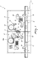
Figure 1 is a view from above of a possible embodiment of a machine for filling and sealing bottles, cartridges, syringes and the like, according to the invention; -
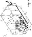
Figure 2 is a partially cutaway perspective view from the front of a first portion of the machine inFigure 1 ; -
Figure 3 is a partially cutaway perspective view from the rear of a first portion of the machine inFigure 1 ; -
Figure 4 is a partially cutaway perspective view from the front of a second portion of the machine inFigure 1 ; -
Figure 5 is a partially cutaway perspective view from the rear of a second portion of the machine inFigure 1 ; -
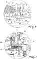
Figure 6 is a perspective view of an enlarged detail of a first portion of the machine inFigure 1 in the step of delivering the crimp-capped containers to a second nest; -
Figure 7 is a perspective view of an enlarged detail of a second portion of the machine inFigure 1 in the step of picking up the empty containers from a first nest; -
Figure 8 is a perspective view of an enlarged detail of a third portion of the machine inFigure 1 in the step of filling the empty containers; -
Figure 9 is a perspective view of an enlarged detail of a fourth portion of the machine inFigure 1 in the step of weighing the containers. - With reference to the figures, the
reference numeral 1 generally designates a machine for filling and sealing bottles, cartridges, syringes and the like, which are generally termed containers A. - The method according to the invention is adapted to fill and seal containers A (which, as indicated previously, can be interchangeably bottles, cartridges, syringes and the like) which are accommodated individually within respective seats of a first nest B which in turn is contained in a first transport tub C.
- Firstly it is necessary to supply the containers A (which will be empty and sterile) which are accommodated individually in the respective seats of the first nest B.
- Then comes the extraction of at least one individual container A at a time from the first nest B and its transfer to a
filling station 2 in order to fill such at least one container A with a substance. - The filling substance can be any, usually in liquid or powder form, and the quantity of substance introduced can be regulated according to the specific requirements and the capacity of the container A being processed.
- Then comes a step of transferring the at least one filled container A to a
crimp capping station 3, passing through a separatingpartition 4. - Once it has reached the
crimp capping station 3 it will be possible to crimp cap the container A at thatstation 3. - The container A fitted with the crimp cap F which is conveniently locked onto the neck of the container so as to define a closing seal, can then be inserted in a respective seat of a second nest D.
- In order to verify the exact weight of the empty container A (in order to carry out successive checks on the correct filling), after having extracted it from the first nest B and before filling it, each container A is weighed when it is empty.
- In order to verify that the right quantity of filling substance is introduced into the container A it is further necessary to weigh the at least one individual container A after filling it: a management and control unit will be able to determine the weight of the introduced substance (from the difference between the weight of the full container A and the weight of the same container A when empty) and verify its correspondence to the preset standards. If an incorrect quantity of the introduced substance is found, it will be possible to identify the specific container A in order to discard it or subject it to intervention by an operator.
- In order to prevent the introduced substance in the container A from being contaminated through contact with dust and/or the like (for example present in suspension in the air) it is advisable, immediately after each container A has been filled, to juxtapose a closure stopper (actually this is a protective stopper that, although not coupled stably to the corresponding container A and therefore not adapted to completely close it, is placed as barrier against any contaminants that may be present in the working environment) against the opening of the at least one container A. In this manner any exchange is avoided between the external environment and the inside of the container A, in which the introduced substance is present.
- Moreover, the placing of a stopper is extremely advantageous because of the fact that some substances (in use in the pharmaceutical, chemical and biotechnological sectors) are highly volatile and therefore the presence of the stopper ensures that they are not dispersed into the environment before the sealing.
- For the purpose of preventing the entry of dust or other contaminants into the
filling station 2, a higher pressure is established in thefilling station 2, which is located upstream of the separatingpartition 4, with respect to thecrimp capping station 3, which is located downstream of the separating partition 4 (with respect to the direction of advancement of the containers A inside the machine 1). - This condition can be ensured by using a conveyed air circuit which is already present in the installation area of the
machine 1, or by providing specific compressors or other, similar devices adapted to achieving this end. - The
machine 1 for filling and sealing containers A will therefore comprise afilling station 2 and acrimp capping station 3 between which the aforementioned separatingpartition 4 is interposed. - Both
stations partition 4 will be supported by aconventional frame 5 placed on the ground and connected to respective power supply circuits (for example there will be a connection to the mains electricity supply and, optionally, there will be a connection to at least one data network and to a circuit for supplying conveyed/compressed air). - The
filling station 2, according to the invention, comprises, mainly, a firstselective handling unit 6 which is designed to extract at least one individual container A at a time from the first nest B. - Once the container A has been extracted, the first
selective handling unit 6 will align it with adispenser 7 for filling the container A with the desired substance. - The
dispenser 7 will comprise at least one nozzle which can be inserted (at least partially) into the container A, in order to release the substance. - The
dispenser 7 will preferably comprise an internal dosage measurer which is designed to control the quantity of substance introduced into the container A at each dispensing: the dosage measurer will be programmable so as to define in each instance the appropriate quantity of substance as a function of the capacity of the containers A with which to work and according to the specific packaging requirements of the particular pharmaceutical, chemical and/or biological/biotechnological substance. - The first
selective handling unit 6 will then therefore provide to juxtapose the container A against atransfer device 8 in thecrimp capping station 3, beyond thepartition 4. - The
crimp capping station 3, according to the invention, comprises, mainly, a secondselective handling unit 9 for picking up the at least one container A from thetransfer device 8 and aligning it with acrimp capping unit 10 in order to juxtapose and fix a crimp cap F against the top of the container A. - Upstream of the
crimp capping unit 10 there is preferably adistributor 11 of crimp caps F which deposits a crimp cap F on the top of each container A, so that the containers A arrive at thecrimp capping unit 10 already topped by a respective crimp cap F, thus speeding up the sealing of the container A with such crimp cap F. - The
distributor 11 can preferably be of the "break-off' type in which the container A passes below a region of thedistributor 11, brushing against a crimp cap F protruding from that region and picking it up during such passage. - The crimp caps F arrive conveniently aligned with the
distributor 11 by way of an automatic vibratingorientator 12 of the type comprising a substantially cylindrical collector drum on the side walls of which there is a track for the ordered conveyance of the crimp caps F. - The second
selective handling unit 9 lastly delivers the crimp capped container A in a seat of a second nest D. - It should be noted that the first
selective handling unit 6 and the secondselective handling unit 9 can advantageously be constituted by anthropomorphic robots, articulated arms and/or multi-axis movers, of substantially known type. - According to a particular embodiment of undoubted practical and applicative interest, the
machine 1 comprises, further, aconveyor belt 13 for the transport tubs C and E, which contain the nests B and D. - The
conveyor belt 13 affects theentire machine 1, defining a path along one side thereof for the tubs C and E: the tubs C and E, along theline 13, can move from a position of alignment with afirst grip element 14, which is designed to transfer the first nest B from the respective tub C arranged on theconveyor belt 13 to the firstselective handling unit 6, to a second position of alignment with asecond grip element 14 for the transfer of the second nest D from the secondselective handling unit 9 to theconveyor belt 13. - The
conveyor belt 13 can be simply constituted by a conveyor belt on which the tubs C and E are resting, in such case there will be moveable appendages for stopping the tubs C and E in preset positions; alternatively, the possibility exists of providing thebelt 13 by way of conveyor chains provided with "drawers" (in general, with dedicated receptacles) through which to control the position of each tub C and E instant by instant. - The
machine 1, in order to prevent the entry into the fillingstation 2 of contaminants (from the external environment and/or from the crimp capping station 3), comprises, in thefirst filling station 2, pneumatic elements for injecting gas (conveyed air) in order to maintain, inside thestation 2, a pressure higher than the ambient pressure and than the pressure present in thecrimp capping station 3. - In this manner the circulation of gas (air) can occur only from the inside of the filling
station 2 outwardly, thus preventing the reverse direction of circulation which could permit the entry of contaminants. - The presence of the separating
partition 4 and the establishment of an overpressure inside the fillingstation 2 ensure that the substance introduced into the containers A cannot be subjected to contamination, in conformance with the requirements of the pharmaceutical, chemical and biological/biotechnological industries. - In particular, in the pharmaceutical sector regulations require measures to be taken which are aimed at minimizing contamination. Conventional machines, in fact, adopt technical solutions that reduce the risk of contamination, but none of these is capable of rendering it almost negligible, as can be achieved with the
machine 1 according to the invention. - The isolation of the environments defined inside the filling
station 2 and thecrimp capping station 3, which is obtained by way of thepartition 4, is safeguarded thanks to the presence of atransfer device 8 which comprises a rotating carousel affected by thepartition 4 substantially at its centerline. - The carousel is provided with respective substantially perimetric seats for the temporary accommodation of the containers A.
- A rotation of the carousel is therefore adapted to transfer the containers A that are in the seats arranged in the filling
station 2 beyond thepartition 4, to thecrimp capping station 3. - According to a possible embodiment that involves the adoption of optional components (which can contribute to a better operation of the
machine 1 according to the invention but which are not essential for that operation) the carousel and thepartition 4 will be shaped so as to have dividers, either fixed or moveable (usually closed): moveable dividers can temporarily open, allowing the passage through of the containers A. - In the short period for which the moveable dividers will be open, the overpressure present in the filling
station 2 will ensure that the flow of air that will be established through the open gaps will be directed from the fillingstation 2 to thecrimp capping station 3, thus preventing reverse-direction flows that could result in the entry of contaminants into the fillingstation 2. - For fixed dividers, the slit left open by them will allow the limited passage of air: such limitation, combined with the presence of the overpressure in the filling
station 2, will prevent the entry of contaminants into the station 2 (the speed of the flow of air that passes through the slits to flow into thecrimp capping station 3 will be such as to prevent any contaminants from being able to ascend against the current). - In order to have an exact verification of the quantity of substance introduced into each container A, the filling
station 2 comprises at least oneload cell 15 for detecting the weight of the container A in either the configuration of empty container A, before introducing the filling substance, or the configuration of full container A, after introducing the filling substance, or both configurations. - The
load cell 15 is arranged along the path of the firstselective handling unit 6, between the region for extracting at least one individual container A at a time from the first nest B and the at least one fillingdispenser 7. - Preferably the
load cell 15 will carry out a weighing of the empty container A, before this is aligned with thedispenser 7 for introducing the filling substance, in order to determine the weight of the container A (tare weight) on which themachine 1 is operating at that moment. - After the container A has been filled, it will be sent to the
load cell 15 again for its weighing, thus detecting the overall weight, constituted by the sum of the weight of the container A alone and the weight of the filling substance introduced into it. - In this manner, by way of a processor adapted to process the data from the readings of the
load cell 15, it will be possible to detect with precision the quantity of substance introduced into each container A, so controlling any filling errors and/or overruns with respect to the tolerances envisaged. The processor will be capable of keeping track of the container A that may contain an incorrect quantity of substance in order to eliminate it (subsequently, outside the machine 1) from the production batch. - As already amply shown previously, the
machine 1 achieves the aim of preventing the contamination of the substance introduced into the containers A and/or the contamination of the containers A (when they are still empty and accommodated in the first nest B). - In order to prevent the contamination of the substance present inside the containers A, it should be noted that the
machine 1 further comprises, downstream of the dispenser 7 (for filling) and upstream of thetransfer device 8, an automaticstopper fitting machine 16 for applying a stopper in the opening of at least one container A, thus isolating its contents from the external environment. - This embodiment makes it possible to provide the
transfer device 8 only with stoppered containers A: these therefore will arrive at the crimp capping station 3 (passing through the partition 4) stoppered, a condition that reduces to the minimum the possibility of contamination through dust in suspension (while noting that the containers A will be considered stably closed only after the crimp cap F has been deposited). - This is particularly relevant if we consider that the
crimp capping unit 10 makes plastic deformations in the crimp caps F and therefore it certainly generates a certain quantity of dust, against which it is necessary to protect contents of each container A. - The stoppers will be supplied to the automatic
stopper fitting machine 16 in a configuration of orderly mutual alignment by anorientator 16a which is entirely similar to the automatic vibratingorientator 12 operating on the crimp caps F which was described previously. - It should conveniently be noted that the first
selective handling unit 6 is functionally associated with afirst structure 17, for supporting the first nest B. - The
structure 17 will preferably be able to move on a horizontal plane. - Below the latter there will be at least one
first pusher 18 for lifting at least one container A at a time from the first nest B and delivering it to the firstselective handling unit 6. - In particular the
movable structure 17 will shift the nest B (while keeping it horizontal), progressively causing the alignment of at least one container A with the at least onefirst pusher 18. - Once alignment is achieved, the
pusher 18 will lift, translating the respective container A upwardly and enabling the firstselective handling unit 6 to grasp it. - In order to prevent misalignments of the containers A lifted by the
first pusher 18, there is a sucker on the top of thepusher 18, which is adapted to retain the container A, preserving its vertical orientation (the alignment in general). - Similarly, the second
selective handling unit 9 is functionally associated with asecond structure 19, for supporting the second nest D. - The
second structure 19 will also be moveable on a horizontal plane, and it also will surmount at least onesecond pusher 20 which is designed to receive at least one container A at a time from the secondselective handling unit 9 and to deposit it in a respective seat of the second nest D. - As illustrated previously for what happens in the filling
station 2, in thecrimp capping station 3 themovable structure 19 will shift the nest D (while keeping it horizontal), progressively causing the alignment of at least one container A with the at least onesecond pusher 20. - Once the alignment is achieved, the
pusher 20 will lift by translating upwardly in order to retrieve the at least one container A held by the secondselective handling unit 9. - In order to prevent misalignments of the containers A retrieved by the
second pusher 20, there is a sucker on the top of thepusher 20, which is adapted to retain the container A, preserving its vertical orientation (the alignment in general). - Effectively the present invention solves the above mentioned problems, by providing a method for filling and sealing bottles, cartridges, syringes and the like which is capable of preventing the contamination of processed containers A of the type of bottles, cartridges, syringes and the like with suspended dust and/or volatile substances generated during the closing steps.
- In particular the containers A will not be subjected to the dust generated by the
crimp capping unit 10 which, by making plastic deformations on the metallic material that constitutes the crimp caps F, can put such dust contaminants in suspension in the air present within thecrimp capping station 3. As has been seen, the containers A will reach thecrimp capping station 3 after having been subjected to stoppering and therefore their contents will be protected, from contaminants present in the air, when they are in thecrimp capping station 3. By contrast, when the containers A (still empty or full but without stopper) are located in the fillingstation 2, they cannot be contaminated because the separatingpartition 4 and the presence of an overpressure prevent the entry of contaminants into the fillingstation 2. - Advantageously, the method according to the invention ensures a high qualitative standard of the phials, bottles, cartridges, syringes and the like, filled and closed, that are obtained by the application thereof.
- In fact, although the principal objective of the method according to the invention is to prevent any possible contamination of the containers A and of their contents, it ensures the execution of all the operations envisaged by the most advanced and rigorous conventional methods, thus obtaining a sealed container A that conforms to the highest qualitative standards, the content of which is free from contamination.
- Conveniently, the
machine 1 for filling and sealing bottles, cartridges, syringes and the like is adapted to prevent the contamination of the containers A that are processed by it with suspended dust and/or volatile substances generated by the devices for closing them. - Positively the
machine 1 according to the invention is particularly versatile, and therefore adapted to work interchangeably on bottles, cartridges, syringes and the like, by introducing a specific quantity of pharmaceutical (and/or chemical and/or biological, etc.) substance and adopting the most suitable type of closure for each specific case. - Conveniently the
machine 1 according to the invention, although partially similar to those of the conventional type, adopts an alternative technical and structural architecture to that of conventional packaging machines. - Advantageously, the method and the
machine 1 for filling and sealing bottles, cartridges, syringes and the like can be implemented at low cost, being relatively simple to execute and practical and safe in use. - The invention, thus conceived, is susceptible of numerous modifications and variations, all of which are within the scope of the appended claims. Moreover, all the details may be substituted by other, technically equivalent elements.
- In the embodiments illustrated, individual characteristics shown in relation to specific examples may in reality be interchanged with other, different characteristics, existing in other embodiments.
- In practice, the materials employed, as well as the dimensions, may be any according to requirements and to the state of the art.
- Where technical features mentioned in any claim are followed by reference signs, those reference signs have been included for the sole purpose of increasing the intelligibility of the claims and accordingly, such reference signs do not have any limiting effect on the interpretation of each element identified by way of example by such reference signs.
Claims (11)
- A method for filling and sealing bottles, cartridges, syringes and the like, wherein said bottles, cartridges, syringes and the like, generally termed containers (A), said containers (A) being accommodated individually within respective seats of a first nest (B) which in turn is contained in a first transport tub (C), which consists in:- supplying said containers (A) which are accommodated individually within respective seats of said first nest (B) which in turn is associated with said first transport tub (C);- extracting at least one individual container (A) at a time from the first nest (B) and transferring it to a filling station (2) in order to fill said at least one container (A) with a substance;- transferring said at least one filled container (A) to a crimp capping station (3), passing through a separating partition (4);- crimp capping said at least one container (A) at said crimp capping station (3);- inserting said at least one crimp capped container (A) in a respective seat of a second nest (D);- juxtaposing, before the transfer of said at least one filled container (A) to a crimp capping station (3), passing through a separating partition (4), a closure stopper against an opening of said at least one container (A).
- The method according to claim 1, characterized in that it consists in:- weighing, after the extraction of the at least one individual container (A) from the first nest (B) and before its filling, said at least one container (A).
- The method according to claim 1, characterized in that it consists in:- weighing, after the filling of the at least one individual container (A), said at least one container (A).
- The method according to claim 1, characterized in that it consists in:- establishing a higher pressure in said filling station (2), arranged upstream of said separating partition (4), with respect to the crimp capping station (3), arranged downstream of said separating partition (4).
- A machine for filling and sealing bottles, cartridges, syringes and the like, generally termed containers, said containers (A) being accommodated individually within respective seats of a first nest (B) which in turn is contained in a first transport tub (C), characterized in that it comprises a filling station (2) and a crimp capping station (3), between which a separating partition (4) is interposed, said filling station (2) comprising a first selective handling unit (6) designed to extract at least one individual container (A) at a time from said first nest (B), align it with a dispenser (7) for filling it, and juxtapose it against a transfer device (8) in said crimp capping station (3), said crimp capping station (3) comprising, beyond said partition (4), a second selective handling unit (9) for picking up said at least one container (A) from said transfer device (8), aligning the container (A) with a crimp capping unit (10) for coupling a crimp cap (F) to the top of said container (A), and delivering the crimp capped container (A) to a seat of a second nest (D), and in that it comprises, downstream of said filling dispenser (7) and upstream of said transfer device (8), an automatic stopper fitting machine (16) for applying a stopper in the opening of said at least one container (A).
- The machine according to claim 5, characterized in that it comprises a conveyor belt (13) for said transport tubs (C, E), which contain said nests (B, D), from a position of alignment with a first grip element (14), which is designed to transfer said first nest (B) from the respective tub (C) arranged on the conveyor belt (13) to said first selective handling unit (6), to a second position of alignment with a second grip element (14), for transferring said second nest (D) from said second selective handling unit (9) to said conveyor belt (13).
- The machine according to claim 5, characterized in that said filling station (2) comprises pneumatic elements for injecting conveyed/compressed gas in order to maintain, within said filling station (2), a pressure higher than the ambient pressure and than the pressure present in said crimp capping station (3).
- The machine according to claim 5, characterized in that said transfer device (8) comprises a rotating carousel affected by said partition (4) substantially at its centerline, said carousel being provided with respective substantially perimetric seats for the temporary accommodation of said containers (A), a rotation of said carousel transferring the containers (A) present in the seats arranged in said filling station (2) beyond said partition (4), to said crimp capping station (3).
- The machine according to one or more of the preceding claims, characterized in that said filling station (2) comprises at least one load cell (15) for detecting the weight of the container (A) in either the configuration of empty container (A), before introducing the filling substance, or the configuration of full container (A), after introducing the filling substance, said load cell (15) being arranged along the path of said first selective handling unit (6), substantially between said region for extracting at least one individual container (A) at a time from said first nest (B) and said at least one filling dispenser (7).
- The machine according to one or more of the preceding claims, characterized in that said first selective handling unit (6) is functionally associated with a first structure (17), for supporting said first nest (B), which can move on a horizontal plane, and with at least one first pusher (18), arranged below said first structure (17), for lifting at least one container (A) at a time from said first nest (B) and delivering it to said first selective handling unit (6).
- The machine according to one or more of the preceding claims, characterized in that said second selective handling unit (9) is functionally associated with a second structure (19), for supporting said second nest (D), which can move on a horizontal plane, and with at least one second pusher (20), arranged below said second structure (19), for receiving at least one container (A) at a time from said second selective handling unit (9) and depositing it in a respective seat of said second nest (D).
Applications Claiming Priority (2)
| Application Number | Priority Date | Filing Date | Title |
|---|---|---|---|
| ITUB20151052 | 2015-06-11 | ||
| PCT/EP2016/062880 WO2016198391A1 (en) | 2015-06-11 | 2016-06-07 | Method and machine for filling and sealing bottles, cartridges, syringes and the like |
Publications (2)
| Publication Number | Publication Date |
|---|---|
| EP3307629A1 EP3307629A1 (en) | 2018-04-18 |
| EP3307629B1 true EP3307629B1 (en) | 2019-08-07 |
Family
ID=54150530
Family Applications (1)
| Application Number | Title | Priority Date | Filing Date |
|---|---|---|---|
| EP16730292.6A Active EP3307629B1 (en) | 2015-06-11 | 2016-06-07 | Method and machine for filling and sealing bottles, cartridges, syringes and the like |
Country Status (6)
| Country | Link |
|---|---|
| US (1) | US10829252B2 (en) |
| EP (1) | EP3307629B1 (en) |
| JP (1) | JP6911257B2 (en) |
| CN (1) | CN107735321B (en) |
| ES (1) | ES2750816T3 (en) |
| WO (1) | WO2016198391A1 (en) |
Families Citing this family (27)
| Publication number | Priority date | Publication date | Assignee | Title |
|---|---|---|---|---|
| US10081527B2 (en) * | 2012-05-03 | 2018-09-25 | Vanrx Pharmasystems Inc. | Cover removal system for use in controlled environment enclosures |
| JP6911257B2 (en) | 2015-06-11 | 2021-07-28 | アイ.エム.エー. インダストリア マシーン オートマチック エス.ピー.エー. イン シグラ アイエムエー エス.ピー.エー.I.M.A. Industria Macchine Automatiche S.P.A In Sigla Ima S.P.A | Methods and machines for filling and sealing bottles, cartridges, syringes, etc. |
| IT201600074164A1 (en) * | 2016-07-15 | 2018-01-15 | Nuova Ompi Srl | METHOD OF MANIPULATION OF PRIMARY CONTAINERS FOR PHARMACEUTICAL USE TRANSPORTED ALONG A AUTOMATIC TREATMENT LINE OPERATING IN A CONTROLLED ENVIRONMENT |
| DK3335844T3 (en) * | 2016-12-15 | 2020-01-06 | Pharma Integration S R L | CONSTRUCTIVE STRUCTURE OF AN INCLUSION DETERMINED FOR AUTOMATED PRODUCTION OF PHARMACEUTICAL OR BIOTECHNICAL ARTICLES |
| CN106892392B (en) * | 2017-03-06 | 2023-08-15 | 广东中德压力容器有限公司 | Automatic curing agent pouring equipment |
| DE102017207307A1 (en) * | 2017-03-13 | 2018-09-13 | Bausch + Ströbel Maschinenfabrik Ilshofen GmbH + Co. KG | System with alternating filling of containers and method for this |
| CN106864791A (en) * | 2017-04-21 | 2017-06-20 | 山东新华医疗器械股份有限公司 | A kind of precharging type syringe train line bulking system |
| IT201700094800A1 (en) * | 2017-08-21 | 2019-02-21 | Lameplast Spa | PLANT FOR THE PRODUCTION OF CONTAINERS, PARTICULARLY CONTAINERS FOR MEDICAL, PHARMACEUTICAL, COSMETIC, FOOD OR SIMILAR PRODUCTS |
| CA3085289A1 (en) | 2017-12-11 | 2019-06-20 | Glaxosmithkline Intellectual Property Development Limited | Modular aseptic production system |
| IT201800004068A1 (en) * | 2018-03-29 | 2019-09-29 | Marchesini Group Spa | MACHINE FOR FILLING AND CLOSING PHARMACEUTICAL CONTAINERS, SUCH AS SYRINGES, BOTTLES AND SIMILAR |
| IT201800006483A1 (en) * | 2018-06-20 | 2019-12-20 | EQUIPMENT FOR EXTRACTING PHARMACEUTICAL CONTAINERS SUCH AS SYRINGES, CARPULES OR BOTTLES, FROM THE RELATIVE SUPPORT ELEMENTS CONSISTING OF A TUB AND A NEST | |
| IT201800006485A1 (en) * | 2018-06-20 | 2019-12-20 | EQUIPMENT FOR EXTRACTING PHARMACEUTICAL CONTAINERS, SUCH AS BOTTLES, FROM THE RELATIVE SUPPORT ELEMENTS CONSISTING OF A TRAY | |
| CN108862170B (en) * | 2018-06-21 | 2023-10-10 | 湖南爱米家智能科技有限公司 | Intelligent robot for high-end pharmacy, medicine dispensing, packaging, detection and transportation and application method thereof |
| DE102019202726A1 (en) * | 2019-02-28 | 2020-09-03 | Syntegon Technology Gmbh | Device for transporting at least one object, in particular a pharmaceutical container |
| DE102019207282A1 (en) * | 2019-05-18 | 2020-11-19 | Syntegon Technology Gmbh | Machine arrangement and method for filling and closing containers |
| US20210171231A1 (en) * | 2019-12-09 | 2021-06-10 | Revessel Inc | Robotic automated filling and capping system for vape oil cartridges |
| DE102020102768A1 (en) | 2020-02-04 | 2021-08-05 | Groninger & Co. Gmbh | Isolator system for filling a container with a liquid, transfer station for transferring a container and method therefor |
| IT202000008944A1 (en) | 2020-04-24 | 2021-10-24 | Romaco Srl | EQUIPMENT FOR FILLING CONTAINERS WITH A POWDER MATERIAL |
| IT202000008974A1 (en) * | 2020-04-24 | 2021-10-24 | Romaco Srl | EQUIPMENT FOR FILLING CONTAINERS WITH A POWDER MATERIAL |
| FR3117459B1 (en) * | 2020-12-14 | 2022-12-16 | Cenexi Laborathoires Thissen | METHOD FOR ASSEMBLING AND FILLING CONTAINERS FOR A NEEDLELESS INJECTION DEVICE |
| BE1028884B1 (en) * | 2020-12-14 | 2022-07-12 | Cenexi Laborathoires Thissen | METHOD FOR ASSEMBLING AND FILLING CONTAINERS FOR A NEEDLELESS INJECTION DEVICE |
| EP4259527A1 (en) * | 2020-12-14 | 2023-10-18 | Cenexi - Laborathoires Thissen | Method for assembling and filling containers for a needleless injection device |
| DE102020134859A1 (en) * | 2020-12-23 | 2022-06-23 | Bausch + Ströbel Maschinenfabrik Ilshofen GmbH + Co. KG | Device for processing pharmaceutical containers and filling device |
| DE102020134866A1 (en) * | 2020-12-23 | 2022-06-23 | Bausch + Ströbel Maschinenfabrik Ilshofen GmbH + Co. KG | Device for filling pharmaceutical containers |
| IT202100000311A1 (en) * | 2021-01-11 | 2022-07-11 | Pharma Integration S R L | DEVICE FOR MOVING CONTAINERS, APPARATUS AND METHOD FOR PRODUCING PHARMACEUTICAL OR BIOTECHNOLOGICAL ITEMS |
| CN114408487B (en) * | 2022-01-20 | 2023-11-10 | 东富龙科技集团股份有限公司 | Device for removing bottles from honeycomb containers |
| CN114715448B (en) * | 2022-06-09 | 2022-08-26 | 北京先通国际医药科技股份有限公司 | Radiopharmaceutical subpackage system, method and application thereof |
Citations (7)
| Publication number | Priority date | Publication date | Assignee | Title |
|---|---|---|---|---|
| US20030056466A1 (en) | 2001-09-27 | 2003-03-27 | Shigenori Muneyasu | Solution filling and plugging system to a container |
| DE10345338A1 (en) | 2003-09-21 | 2005-04-14 | Inova Pharma Systems Gmbh | Method and device for controlled filling |
| DE102004005342A1 (en) | 2004-02-04 | 2005-09-01 | Khs Maschinen- Und Anlagenbau Ag | Plant for the aseptic filling of a liquid filling material |
| US20060136095A1 (en) | 2004-12-22 | 2006-06-22 | Rob Ronald H | Automated pharmacy admixture system (APAS) |
| DE102008001287A1 (en) | 2008-04-21 | 2009-10-22 | Robert Bosch Gmbh | Filling and closing machine for containers |
| DE102009041215A1 (en) | 2009-09-11 | 2011-03-24 | Krones Ag | Method and apparatus for stretch blow molding or blow molding and filling sterile containers |
| DE102011113358A1 (en) | 2011-09-15 | 2013-03-21 | Groninger & Co. Gmbh | Method and device for filling and closing pharmaceutical objects |
Family Cites Families (22)
| Publication number | Priority date | Publication date | Assignee | Title |
|---|---|---|---|---|
| US6189292B1 (en) * | 1998-03-13 | 2001-02-20 | Becton Dickinson And Company | Method and apparatus for manufacturing, filling and packaging medical devices and medical containers |
| DE19819813C2 (en) * | 1998-05-04 | 2000-11-02 | Olympus Diagnostica Gmbh | Use of a laboratory primary sample distributor for archiving |
| US7707807B2 (en) * | 2004-03-08 | 2010-05-04 | Medical Instill Technologies, Inc. | Apparatus for molding and assembling containers with stoppers and filling same |
| ES2232269B1 (en) * | 2003-01-21 | 2006-03-01 | Grifols, S.A. | PROCEDURE FOR THE STERILE DOSAGE OF ROADS. |
| FR2860978B1 (en) * | 2003-10-20 | 2006-03-03 | Valois Sas | TANK SUPPORT DEVICE AND STERILIZATION ASSEMBLY HAVING SUCH A DEVICE. |
| DE102005026986A1 (en) * | 2005-06-10 | 2006-12-14 | Robert Bosch Gmbh | Device for filling and closing containers |
| ATE396952T1 (en) * | 2005-11-16 | 2008-06-15 | Arol Spa | DEVICE AND METHOD FOR CLOSING CONTAINERS |
| DE102007023400A1 (en) * | 2006-12-12 | 2008-06-19 | Robert Bosch Gmbh | Tactical machine for filling containers |
| JP2008247413A (en) * | 2007-03-29 | 2008-10-16 | House Foods Corp | Conveying apparatus of thin-walled container having neck ring |
| DE102008030268B3 (en) * | 2008-06-19 | 2010-02-04 | Arzneimittel Gmbh Apotheker Vetter & Co. Ravensburg | Method for filling dual-chamber systems in pre-sterilizable carrier systems and pre-sterilisable carrier system |
| IT1390858B1 (en) * | 2008-08-05 | 2011-10-19 | Dachi S R L | "LOADING AND UNLOADING OF BIOLOGICAL MATERIAL CONTAINERS IN AN AUTOMATION SYSTEM" |
| DE102009027452A1 (en) * | 2009-07-03 | 2011-01-05 | Robert Bosch Gmbh | Device for filling and closing pharmaceutical containers |
| EP2464456A2 (en) * | 2009-08-10 | 2012-06-20 | West Pharmaceutical Services, Inc. | Apparatus and method for filling flangeless containers |
| IT1400953B1 (en) * | 2010-06-14 | 2013-07-05 | Marchesini Group Spa | BOTTLE PACKAGING MACHINE |
| US20140034545A1 (en) * | 2012-05-03 | 2014-02-06 | Schott Ag | Holding structure for simultaneously holding a plurality of containers for medical, pharmaceutical or cosmetic applications and transport or packaging container with holding structure |
| CN104272049B (en) * | 2012-05-03 | 2017-04-12 | 肖特公开股份有限公司 | Method for treating containers and substances stored therein for medical, pharmaceutical or cosmetic applications |
| JP5951768B2 (en) * | 2012-06-26 | 2016-07-13 | テルモ株式会社 | Syringe storage container |
| TWI481804B (en) * | 2012-10-03 | 2015-04-21 | Wei Hua Chaing | Automatic rail guided vehicle for manufacturing medicament |
| TW201900137A (en) | 2013-08-16 | 2019-01-01 | 加拿大商凡爾克斯醫藥系統公司 | Method, device and system for filling and lyophilizing drug containers |
| HUE044371T2 (en) * | 2015-04-17 | 2019-10-28 | Schott Kaisha Pvt Ltd | Supporting structure for sealed cartridges, transport or packaging container and process |
| JP6911257B2 (en) | 2015-06-11 | 2021-07-28 | アイ.エム.エー. インダストリア マシーン オートマチック エス.ピー.エー. イン シグラ アイエムエー エス.ピー.エー.I.M.A. Industria Macchine Automatiche S.P.A In Sigla Ima S.P.A | Methods and machines for filling and sealing bottles, cartridges, syringes, etc. |
| CN105540520B (en) * | 2015-12-31 | 2017-08-04 | 楚天科技股份有限公司 | A kind of pre-encapsulated injector bottle placer |
-
2016
- 2016-06-07 JP JP2017563322A patent/JP6911257B2/en active Active
- 2016-06-07 US US15/579,865 patent/US10829252B2/en active Active
- 2016-06-07 WO PCT/EP2016/062880 patent/WO2016198391A1/en active Application Filing
- 2016-06-07 EP EP16730292.6A patent/EP3307629B1/en active Active
- 2016-06-07 ES ES16730292T patent/ES2750816T3/en active Active
- 2016-06-07 CN CN201680034076.3A patent/CN107735321B/en active Active
Patent Citations (7)
| Publication number | Priority date | Publication date | Assignee | Title |
|---|---|---|---|---|
| US20030056466A1 (en) | 2001-09-27 | 2003-03-27 | Shigenori Muneyasu | Solution filling and plugging system to a container |
| DE10345338A1 (en) | 2003-09-21 | 2005-04-14 | Inova Pharma Systems Gmbh | Method and device for controlled filling |
| DE102004005342A1 (en) | 2004-02-04 | 2005-09-01 | Khs Maschinen- Und Anlagenbau Ag | Plant for the aseptic filling of a liquid filling material |
| US20060136095A1 (en) | 2004-12-22 | 2006-06-22 | Rob Ronald H | Automated pharmacy admixture system (APAS) |
| DE102008001287A1 (en) | 2008-04-21 | 2009-10-22 | Robert Bosch Gmbh | Filling and closing machine for containers |
| DE102009041215A1 (en) | 2009-09-11 | 2011-03-24 | Krones Ag | Method and apparatus for stretch blow molding or blow molding and filling sterile containers |
| DE102011113358A1 (en) | 2011-09-15 | 2013-03-21 | Groninger & Co. Gmbh | Method and device for filling and closing pharmaceutical objects |
Also Published As
| Publication number | Publication date |
|---|---|
| JP6911257B2 (en) | 2021-07-28 |
| WO2016198391A1 (en) | 2016-12-15 |
| ES2750816T3 (en) | 2020-03-27 |
| EP3307629A1 (en) | 2018-04-18 |
| CN107735321A (en) | 2018-02-23 |
| CN107735321B (en) | 2020-04-10 |
| US10829252B2 (en) | 2020-11-10 |
| US20180162572A1 (en) | 2018-06-14 |
| JP2018517626A (en) | 2018-07-05 |
Similar Documents
| Publication | Publication Date | Title |
|---|---|---|
| EP3307629B1 (en) | Method and machine for filling and sealing bottles, cartridges, syringes and the like | |
| US11186390B2 (en) | Method for filling pharmaceutical containers | |
| US9156598B2 (en) | Packaging structure for containers for pharmaceutical use | |
| CN107531339A (en) | For closing the method, the supporting construction for supporting case closure member and transport or packing container of box | |
| CN111278737B (en) | Method and device for flexible handling of pharmaceutical packaging | |
| US9283146B2 (en) | Machine and method for the automatic preparation of intravenous medication | |
| US11325736B2 (en) | Extraction assembly of a content from a bag for pharmaceutical and chemical sectors | |
| CA2977087A1 (en) | Packaging structure for containers for pharmaceutical use | |
| US20210253279A1 (en) | An apparatus for extracting pharmaceutical containers, such as syringes, carpules or vials, from relative support elements constituted by a tub and a nest | |
| CN111902342B (en) | Machine for filling and closing pharmaceutical containers, such as syringes, vials and the like | |
| CA3128096A1 (en) | Apparatus for transporting at least one object, in particular a pharmaceutical container | |
| US20230406554A1 (en) | Device for processing pharmaceutical containers, and filling device |
Legal Events
| Date | Code | Title | Description |
|---|---|---|---|
| STAA | Information on the status of an ep patent application or granted ep patent |
Free format text: STATUS: THE INTERNATIONAL PUBLICATION HAS BEEN MADE |
|
| PUAI | Public reference made under article 153(3) epc to a published international application that has entered the european phase |
Free format text: ORIGINAL CODE: 0009012 |
|
| STAA | Information on the status of an ep patent application or granted ep patent |
Free format text: STATUS: REQUEST FOR EXAMINATION WAS MADE |
|
| 17P | Request for examination filed |
Effective date: 20171214 |
|
| AK | Designated contracting states |
Kind code of ref document: A1 Designated state(s): AL AT BE BG CH CY CZ DE DK EE ES FI FR GB GR HR HU IE IS IT LI LT LU LV MC MK MT NL NO PL PT RO RS SE SI SK SM TR |
|
| AX | Request for extension of the european patent |
Extension state: BA ME |
|
| DAV | Request for validation of the european patent (deleted) | ||
| DAX | Request for extension of the european patent (deleted) | ||
| GRAP | Despatch of communication of intention to grant a patent |
Free format text: ORIGINAL CODE: EPIDOSNIGR1 |
|
| STAA | Information on the status of an ep patent application or granted ep patent |
Free format text: STATUS: GRANT OF PATENT IS INTENDED |
|
| INTG | Intention to grant announced |
Effective date: 20181218 |
|
| GRAS | Grant fee paid |
Free format text: ORIGINAL CODE: EPIDOSNIGR3 |
|
| GRAA | (expected) grant |
Free format text: ORIGINAL CODE: 0009210 |
|
| STAA | Information on the status of an ep patent application or granted ep patent |
Free format text: STATUS: THE PATENT HAS BEEN GRANTED |
|
| AK | Designated contracting states |
Kind code of ref document: B1 Designated state(s): AL AT BE BG CH CY CZ DE DK EE ES FI FR GB GR HR HU IE IS IT LI LT LU LV MC MK MT NL NO PL PT RO RS SE SI SK SM TR |
|
| REG | Reference to a national code |
Ref country code: GB Ref legal event code: FG4D |
|
| REG | Reference to a national code |
Ref country code: CH Ref legal event code: EP Ref country code: AT Ref legal event code: REF Ref document number: 1163477 Country of ref document: AT Kind code of ref document: T Effective date: 20190815 |
|
| REG | Reference to a national code |
Ref country code: DE Ref legal event code: R096 Ref document number: 602016018149 Country of ref document: DE |
|
| REG | Reference to a national code |
Ref country code: IE Ref legal event code: FG4D |
|
| REG | Reference to a national code |
Ref country code: NL Ref legal event code: MP Effective date: 20190807 |
|
| REG | Reference to a national code |
Ref country code: LT Ref legal event code: MG4D |
|
| PG25 | Lapsed in a contracting state [announced via postgrant information from national office to epo] |
Ref country code: PT Free format text: LAPSE BECAUSE OF FAILURE TO SUBMIT A TRANSLATION OF THE DESCRIPTION OR TO PAY THE FEE WITHIN THE PRESCRIBED TIME-LIMIT Effective date: 20191209 Ref country code: NO Free format text: LAPSE BECAUSE OF FAILURE TO SUBMIT A TRANSLATION OF THE DESCRIPTION OR TO PAY THE FEE WITHIN THE PRESCRIBED TIME-LIMIT Effective date: 20191107 Ref country code: LT Free format text: LAPSE BECAUSE OF FAILURE TO SUBMIT A TRANSLATION OF THE DESCRIPTION OR TO PAY THE FEE WITHIN THE PRESCRIBED TIME-LIMIT Effective date: 20190807 Ref country code: NL Free format text: LAPSE BECAUSE OF FAILURE TO SUBMIT A TRANSLATION OF THE DESCRIPTION OR TO PAY THE FEE WITHIN THE PRESCRIBED TIME-LIMIT Effective date: 20190807 Ref country code: BG Free format text: LAPSE BECAUSE OF FAILURE TO SUBMIT A TRANSLATION OF THE DESCRIPTION OR TO PAY THE FEE WITHIN THE PRESCRIBED TIME-LIMIT Effective date: 20191107 Ref country code: FI Free format text: LAPSE BECAUSE OF FAILURE TO SUBMIT A TRANSLATION OF THE DESCRIPTION OR TO PAY THE FEE WITHIN THE PRESCRIBED TIME-LIMIT Effective date: 20190807 Ref country code: HR Free format text: LAPSE BECAUSE OF FAILURE TO SUBMIT A TRANSLATION OF THE DESCRIPTION OR TO PAY THE FEE WITHIN THE PRESCRIBED TIME-LIMIT Effective date: 20190807 Ref country code: SE Free format text: LAPSE BECAUSE OF FAILURE TO SUBMIT A TRANSLATION OF THE DESCRIPTION OR TO PAY THE FEE WITHIN THE PRESCRIBED TIME-LIMIT Effective date: 20190807 |
|
| REG | Reference to a national code |
Ref country code: AT Ref legal event code: MK05 Ref document number: 1163477 Country of ref document: AT Kind code of ref document: T Effective date: 20190807 |
|
| PG25 | Lapsed in a contracting state [announced via postgrant information from national office to epo] |
Ref country code: GR Free format text: LAPSE BECAUSE OF FAILURE TO SUBMIT A TRANSLATION OF THE DESCRIPTION OR TO PAY THE FEE WITHIN THE PRESCRIBED TIME-LIMIT Effective date: 20191108 Ref country code: LV Free format text: LAPSE BECAUSE OF FAILURE TO SUBMIT A TRANSLATION OF THE DESCRIPTION OR TO PAY THE FEE WITHIN THE PRESCRIBED TIME-LIMIT Effective date: 20190807 Ref country code: AL Free format text: LAPSE BECAUSE OF FAILURE TO SUBMIT A TRANSLATION OF THE DESCRIPTION OR TO PAY THE FEE WITHIN THE PRESCRIBED TIME-LIMIT Effective date: 20190807 Ref country code: RS Free format text: LAPSE BECAUSE OF FAILURE TO SUBMIT A TRANSLATION OF THE DESCRIPTION OR TO PAY THE FEE WITHIN THE PRESCRIBED TIME-LIMIT Effective date: 20190807 Ref country code: IS Free format text: LAPSE BECAUSE OF FAILURE TO SUBMIT A TRANSLATION OF THE DESCRIPTION OR TO PAY THE FEE WITHIN THE PRESCRIBED TIME-LIMIT Effective date: 20191207 |
|
| REG | Reference to a national code |
Ref country code: ES Ref legal event code: FG2A Ref document number: 2750816 Country of ref document: ES Kind code of ref document: T3 Effective date: 20200327 |
|
| PG25 | Lapsed in a contracting state [announced via postgrant information from national office to epo] |
Ref country code: TR Free format text: LAPSE BECAUSE OF FAILURE TO SUBMIT A TRANSLATION OF THE DESCRIPTION OR TO PAY THE FEE WITHIN THE PRESCRIBED TIME-LIMIT Effective date: 20190807 |
|
| PG25 | Lapsed in a contracting state [announced via postgrant information from national office to epo] |
Ref country code: AT Free format text: LAPSE BECAUSE OF FAILURE TO SUBMIT A TRANSLATION OF THE DESCRIPTION OR TO PAY THE FEE WITHIN THE PRESCRIBED TIME-LIMIT Effective date: 20190807 Ref country code: DK Free format text: LAPSE BECAUSE OF FAILURE TO SUBMIT A TRANSLATION OF THE DESCRIPTION OR TO PAY THE FEE WITHIN THE PRESCRIBED TIME-LIMIT Effective date: 20190807 Ref country code: EE Free format text: LAPSE BECAUSE OF FAILURE TO SUBMIT A TRANSLATION OF THE DESCRIPTION OR TO PAY THE FEE WITHIN THE PRESCRIBED TIME-LIMIT Effective date: 20190807 Ref country code: RO Free format text: LAPSE BECAUSE OF FAILURE TO SUBMIT A TRANSLATION OF THE DESCRIPTION OR TO PAY THE FEE WITHIN THE PRESCRIBED TIME-LIMIT Effective date: 20190807 Ref country code: PL Free format text: LAPSE BECAUSE OF FAILURE TO SUBMIT A TRANSLATION OF THE DESCRIPTION OR TO PAY THE FEE WITHIN THE PRESCRIBED TIME-LIMIT Effective date: 20190807 |
|
| REG | Reference to a national code |
Ref country code: DE Ref legal event code: R026 Ref document number: 602016018149 Country of ref document: DE |
|
| PLBI | Opposition filed |
Free format text: ORIGINAL CODE: 0009260 |
|
| PG25 | Lapsed in a contracting state [announced via postgrant information from national office to epo] |
Ref country code: SK Free format text: LAPSE BECAUSE OF FAILURE TO SUBMIT A TRANSLATION OF THE DESCRIPTION OR TO PAY THE FEE WITHIN THE PRESCRIBED TIME-LIMIT Effective date: 20190807 Ref country code: CZ Free format text: LAPSE BECAUSE OF FAILURE TO SUBMIT A TRANSLATION OF THE DESCRIPTION OR TO PAY THE FEE WITHIN THE PRESCRIBED TIME-LIMIT Effective date: 20190807 Ref country code: IS Free format text: LAPSE BECAUSE OF FAILURE TO SUBMIT A TRANSLATION OF THE DESCRIPTION OR TO PAY THE FEE WITHIN THE PRESCRIBED TIME-LIMIT Effective date: 20200224 Ref country code: SM Free format text: LAPSE BECAUSE OF FAILURE TO SUBMIT A TRANSLATION OF THE DESCRIPTION OR TO PAY THE FEE WITHIN THE PRESCRIBED TIME-LIMIT Effective date: 20190807 |
|
| 26 | Opposition filed |
Opponent name: GRONINGER & CO. GMBH Effective date: 20200505 |
|
| PLAX | Notice of opposition and request to file observation + time limit sent |
Free format text: ORIGINAL CODE: EPIDOSNOBS2 |
|
| PG2D | Information on lapse in contracting state deleted |
Ref country code: IS |
|
| PG25 | Lapsed in a contracting state [announced via postgrant information from national office to epo] |
Ref country code: SI Free format text: LAPSE BECAUSE OF FAILURE TO SUBMIT A TRANSLATION OF THE DESCRIPTION OR TO PAY THE FEE WITHIN THE PRESCRIBED TIME-LIMIT Effective date: 20190807 |
|
| PLBB | Reply of patent proprietor to notice(s) of opposition received |
Free format text: ORIGINAL CODE: EPIDOSNOBS3 |
|
| PG25 | Lapsed in a contracting state [announced via postgrant information from national office to epo] |
Ref country code: MC Free format text: LAPSE BECAUSE OF FAILURE TO SUBMIT A TRANSLATION OF THE DESCRIPTION OR TO PAY THE FEE WITHIN THE PRESCRIBED TIME-LIMIT Effective date: 20190807 |
|
| REG | Reference to a national code |
Ref country code: CH Ref legal event code: PL |
|
| PG25 | Lapsed in a contracting state [announced via postgrant information from national office to epo] |
Ref country code: LU Free format text: LAPSE BECAUSE OF NON-PAYMENT OF DUE FEES Effective date: 20200607 |
|
| REG | Reference to a national code |
Ref country code: BE Ref legal event code: MM Effective date: 20200630 |
|
| PG25 | Lapsed in a contracting state [announced via postgrant information from national office to epo] |
Ref country code: IE Free format text: LAPSE BECAUSE OF NON-PAYMENT OF DUE FEES Effective date: 20200607 Ref country code: CH Free format text: LAPSE BECAUSE OF NON-PAYMENT OF DUE FEES Effective date: 20200630 Ref country code: LI Free format text: LAPSE BECAUSE OF NON-PAYMENT OF DUE FEES Effective date: 20200630 |
|
| PG25 | Lapsed in a contracting state [announced via postgrant information from national office to epo] |
Ref country code: BE Free format text: LAPSE BECAUSE OF NON-PAYMENT OF DUE FEES Effective date: 20200630 |
|
| PLCK | Communication despatched that opposition was rejected |
Free format text: ORIGINAL CODE: EPIDOSNREJ1 |
|
| PG25 | Lapsed in a contracting state [announced via postgrant information from national office to epo] |
Ref country code: MT Free format text: LAPSE BECAUSE OF FAILURE TO SUBMIT A TRANSLATION OF THE DESCRIPTION OR TO PAY THE FEE WITHIN THE PRESCRIBED TIME-LIMIT Effective date: 20190807 Ref country code: CY Free format text: LAPSE BECAUSE OF FAILURE TO SUBMIT A TRANSLATION OF THE DESCRIPTION OR TO PAY THE FEE WITHIN THE PRESCRIBED TIME-LIMIT Effective date: 20190807 |
|
| APBM | Appeal reference recorded |
Free format text: ORIGINAL CODE: EPIDOSNREFNO |
|
| APBP | Date of receipt of notice of appeal recorded |
Free format text: ORIGINAL CODE: EPIDOSNNOA2O |
|
| APAH | Appeal reference modified |
Free format text: ORIGINAL CODE: EPIDOSCREFNO |
|
| PG25 | Lapsed in a contracting state [announced via postgrant information from national office to epo] |
Ref country code: MK Free format text: LAPSE BECAUSE OF FAILURE TO SUBMIT A TRANSLATION OF THE DESCRIPTION OR TO PAY THE FEE WITHIN THE PRESCRIBED TIME-LIMIT Effective date: 20190807 |
|
| APBQ | Date of receipt of statement of grounds of appeal recorded |
Free format text: ORIGINAL CODE: EPIDOSNNOA3O |
|
| P01 | Opt-out of the competence of the unified patent court (upc) registered |
Effective date: 20230426 |
|
| PGFP | Annual fee paid to national office [announced via postgrant information from national office to epo] |
Ref country code: FR Payment date: 20230622 Year of fee payment: 8 Ref country code: DE Payment date: 20230627 Year of fee payment: 8 |
|
| PGFP | Annual fee paid to national office [announced via postgrant information from national office to epo] |
Ref country code: IT Payment date: 20230620 Year of fee payment: 8 Ref country code: GB Payment date: 20230620 Year of fee payment: 8 Ref country code: ES Payment date: 20230721 Year of fee payment: 8 |