EP3307497B1 - Druckvorrichtung - Google Patents
Druckvorrichtung Download PDFInfo
- Publication number
- EP3307497B1 EP3307497B1 EP16739558.1A EP16739558A EP3307497B1 EP 3307497 B1 EP3307497 B1 EP 3307497B1 EP 16739558 A EP16739558 A EP 16739558A EP 3307497 B1 EP3307497 B1 EP 3307497B1
- Authority
- EP
- European Patent Office
- Prior art keywords
- rotor
- cutting means
- rotation
- blade
- printing
- Prior art date
- Legal status (The legal status is an assumption and is not a legal conclusion. Google has not performed a legal analysis and makes no representation as to the accuracy of the status listed.)
- Active
Links
Images


Classifications
-
- B—PERFORMING OPERATIONS; TRANSPORTING
- B26—HAND CUTTING TOOLS; CUTTING; SEVERING
- B26D—CUTTING; DETAILS COMMON TO MACHINES FOR PERFORATING, PUNCHING, CUTTING-OUT, STAMPING-OUT OR SEVERING
- B26D1/00—Cutting through work characterised by the nature or movement of the cutting member or particular materials not otherwise provided for; Apparatus or machines therefor; Cutting members therefor
- B26D1/01—Cutting through work characterised by the nature or movement of the cutting member or particular materials not otherwise provided for; Apparatus or machines therefor; Cutting members therefor involving a cutting member which does not travel with the work
- B26D1/04—Cutting through work characterised by the nature or movement of the cutting member or particular materials not otherwise provided for; Apparatus or machines therefor; Cutting members therefor involving a cutting member which does not travel with the work having a linearly-movable cutting member
- B26D1/06—Cutting through work characterised by the nature or movement of the cutting member or particular materials not otherwise provided for; Apparatus or machines therefor; Cutting members therefor involving a cutting member which does not travel with the work having a linearly-movable cutting member wherein the cutting member reciprocates
- B26D1/08—Cutting through work characterised by the nature or movement of the cutting member or particular materials not otherwise provided for; Apparatus or machines therefor; Cutting members therefor involving a cutting member which does not travel with the work having a linearly-movable cutting member wherein the cutting member reciprocates of the guillotine type
- B26D1/085—Cutting through work characterised by the nature or movement of the cutting member or particular materials not otherwise provided for; Apparatus or machines therefor; Cutting members therefor involving a cutting member which does not travel with the work having a linearly-movable cutting member wherein the cutting member reciprocates of the guillotine type for thin material, e.g. for sheets, strips or the like
-
- B—PERFORMING OPERATIONS; TRANSPORTING
- B41—PRINTING; LINING MACHINES; TYPEWRITERS; STAMPS
- B41J—TYPEWRITERS; SELECTIVE PRINTING MECHANISMS, i.e. MECHANISMS PRINTING OTHERWISE THAN FROM A FORME; CORRECTION OF TYPOGRAPHICAL ERRORS
- B41J11/00—Devices or arrangements of selective printing mechanisms, e.g. ink-jet printers or thermal printers, for supporting or handling copy material in sheet or web form
- B41J11/66—Applications of cutting devices
- B41J11/70—Applications of cutting devices cutting perpendicular to the direction of paper feed
-
- B—PERFORMING OPERATIONS; TRANSPORTING
- B26—HAND CUTTING TOOLS; CUTTING; SEVERING
- B26D—CUTTING; DETAILS COMMON TO MACHINES FOR PERFORATING, PUNCHING, CUTTING-OUT, STAMPING-OUT OR SEVERING
- B26D1/00—Cutting through work characterised by the nature or movement of the cutting member or particular materials not otherwise provided for; Apparatus or machines therefor; Cutting members therefor
- B26D1/01—Cutting through work characterised by the nature or movement of the cutting member or particular materials not otherwise provided for; Apparatus or machines therefor; Cutting members therefor involving a cutting member which does not travel with the work
- B26D1/04—Cutting through work characterised by the nature or movement of the cutting member or particular materials not otherwise provided for; Apparatus or machines therefor; Cutting members therefor involving a cutting member which does not travel with the work having a linearly-movable cutting member
- B26D1/06—Cutting through work characterised by the nature or movement of the cutting member or particular materials not otherwise provided for; Apparatus or machines therefor; Cutting members therefor involving a cutting member which does not travel with the work having a linearly-movable cutting member wherein the cutting member reciprocates
- B26D1/08—Cutting through work characterised by the nature or movement of the cutting member or particular materials not otherwise provided for; Apparatus or machines therefor; Cutting members therefor involving a cutting member which does not travel with the work having a linearly-movable cutting member wherein the cutting member reciprocates of the guillotine type
- B26D1/09—Cutting through work characterised by the nature or movement of the cutting member or particular materials not otherwise provided for; Apparatus or machines therefor; Cutting members therefor involving a cutting member which does not travel with the work having a linearly-movable cutting member wherein the cutting member reciprocates of the guillotine type with a plurality of cutting members
- B26D1/095—Cutting through work characterised by the nature or movement of the cutting member or particular materials not otherwise provided for; Apparatus or machines therefor; Cutting members therefor involving a cutting member which does not travel with the work having a linearly-movable cutting member wherein the cutting member reciprocates of the guillotine type with a plurality of cutting members for thin material, e.g. for sheets, strips or the like
-
- B—PERFORMING OPERATIONS; TRANSPORTING
- B26—HAND CUTTING TOOLS; CUTTING; SEVERING
- B26D—CUTTING; DETAILS COMMON TO MACHINES FOR PERFORATING, PUNCHING, CUTTING-OUT, STAMPING-OUT OR SEVERING
- B26D5/00—Arrangements for operating and controlling machines or devices for cutting, cutting-out, stamping-out, punching, perforating, or severing by means other than cutting
- B26D5/08—Means for actuating the cutting member to effect the cut
- B26D5/086—Electric, magnetic, piezoelectric, electro-magnetic means
-
- B—PERFORMING OPERATIONS; TRANSPORTING
- B26—HAND CUTTING TOOLS; CUTTING; SEVERING
- B26D—CUTTING; DETAILS COMMON TO MACHINES FOR PERFORATING, PUNCHING, CUTTING-OUT, STAMPING-OUT OR SEVERING
- B26D5/00—Arrangements for operating and controlling machines or devices for cutting, cutting-out, stamping-out, punching, perforating, or severing by means other than cutting
- B26D5/20—Arrangements for operating and controlling machines or devices for cutting, cutting-out, stamping-out, punching, perforating, or severing by means other than cutting with interrelated action between the cutting member and work feed
-
- B—PERFORMING OPERATIONS; TRANSPORTING
- B41—PRINTING; LINING MACHINES; TYPEWRITERS; STAMPS
- B41J—TYPEWRITERS; SELECTIVE PRINTING MECHANISMS, i.e. MECHANISMS PRINTING OTHERWISE THAN FROM A FORME; CORRECTION OF TYPOGRAPHICAL ERRORS
- B41J11/00—Devices or arrangements of selective printing mechanisms, e.g. ink-jet printers or thermal printers, for supporting or handling copy material in sheet or web form
- B41J11/006—Means for preventing paper jams or for facilitating their removal
-
- B—PERFORMING OPERATIONS; TRANSPORTING
- B41—PRINTING; LINING MACHINES; TYPEWRITERS; STAMPS
- B41J—TYPEWRITERS; SELECTIVE PRINTING MECHANISMS, i.e. MECHANISMS PRINTING OTHERWISE THAN FROM A FORME; CORRECTION OF TYPOGRAPHICAL ERRORS
- B41J11/00—Devices or arrangements of selective printing mechanisms, e.g. ink-jet printers or thermal printers, for supporting or handling copy material in sheet or web form
- B41J11/66—Applications of cutting devices
- B41J11/70—Applications of cutting devices cutting perpendicular to the direction of paper feed
- B41J11/703—Cutting of tape
-
- B—PERFORMING OPERATIONS; TRANSPORTING
- B65—CONVEYING; PACKING; STORING; HANDLING THIN OR FILAMENTARY MATERIAL
- B65H—HANDLING THIN OR FILAMENTARY MATERIAL, e.g. SHEETS, WEBS, CABLES
- B65H35/00—Delivering articles from cutting or line-perforating machines; Article or web delivery apparatus incorporating cutting or line-perforating devices, e.g. adhesive tape dispensers
- B65H35/04—Delivering articles from cutting or line-perforating machines; Article or web delivery apparatus incorporating cutting or line-perforating devices, e.g. adhesive tape dispensers from or with transverse cutters or perforators
- B65H35/06—Delivering articles from cutting or line-perforating machines; Article or web delivery apparatus incorporating cutting or line-perforating devices, e.g. adhesive tape dispensers from or with transverse cutters or perforators from or with blade, e.g. shear-blade, cutters or perforators
-
- B—PERFORMING OPERATIONS; TRANSPORTING
- B26—HAND CUTTING TOOLS; CUTTING; SEVERING
- B26D—CUTTING; DETAILS COMMON TO MACHINES FOR PERFORATING, PUNCHING, CUTTING-OUT, STAMPING-OUT OR SEVERING
- B26D1/00—Cutting through work characterised by the nature or movement of the cutting member or particular materials not otherwise provided for; Apparatus or machines therefor; Cutting members therefor
- B26D1/0006—Cutting members therefor
- B26D2001/0066—Cutting members therefor having shearing means, e.g. shearing blades, abutting blades
-
- B—PERFORMING OPERATIONS; TRANSPORTING
- B26—HAND CUTTING TOOLS; CUTTING; SEVERING
- B26D—CUTTING; DETAILS COMMON TO MACHINES FOR PERFORATING, PUNCHING, CUTTING-OUT, STAMPING-OUT OR SEVERING
- B26D7/00—Details of apparatus for cutting, cutting-out, stamping-out, punching, perforating, or severing by means other than cutting
- B26D2007/0012—Details, accessories or auxiliary or special operations not otherwise provided for
- B26D2007/005—Details, accessories or auxiliary or special operations not otherwise provided for cutters, e.g. guillotines, used in a label maker or printer
Definitions
- the invention relates to a printing apparatus, in particular for printing documents that are separated from a strip by a motor-driven blade.
- the invention can be applied to dispense printed documents such as for example tickets, payment slips, receipts, coupons, vouchers, etc printed on a strip and then separated from the strip.
- the prior art comprises printing apparatuses provided with a motor-driven cutting device that separates the printed documents from a continuous strip.
- One of the problems of known printing apparatuses is the undesired lock of the apparatus due to a jam of the motor-driven blade. This jam may be due, for example, to the malfunction of the cutting device, to the use of unsuitable paper, an incorrect advancement of the paper, etc.
- the jam may be so persistent as not to be solvable by simple retrograde driving of the electric driving motor for driving the blade.
- the manual intervention of an operator is necessary who, with a finger, moves an emergency wheel that protrudes from the case of the printing apparatus and drives the cutting device backwards to solve the jam.
- EP 0870621 A2 discloses an apparatus as in the preamble of claim 1.
- One object of the invention is to make a printing apparatus that is able to overcome one or more of the aforesaid limits and drawbacks of the prior art.
- One advantage is to devise a printing apparatus with a system for unlocking an undesired arrest situation of a motor-driven cutting device that separates a printed document from a strip.
- One advantage is to solve efficiently a jam situation of the blade of the cutting device used in the printing apparatus.
- One advantage is to provide an automated unlocking system that does not require the manual intervention of an operator.
- One advantage is to provide a constructionally simple and cheap system for solving a jam of the blade.
- a printing apparatus comprises the features as defined in claim 1.
- the printing apparatus 1 may comprise, in particular, a magazine for housing printing paper or any other type of printing support.
- the printing support usable by the printing apparatus 1 in question may be, in particular, paper, for example thermal paper.
- "paper” is defined as any type of printing support that is suitable for printing (in particular with a thermal printing head or inkjet), for example a printable material in the form of a strip, in particular wound on a reel, like a reel for (thermal) paper.
- strip is defined not only as a strip of paper unwound from a reel but also other types of printing supports (of known type) like, for example, a set of sheets in continuous fan-fold format, or a set of sheets (for example labels) arranged in a row on a support in the form of strip, etc.
- the magazine may comprise, in particular, at least one seat arranged for receiving at least one reel 2 of (thermal) paper.
- the magazine may nevertheless comprise other embodiments of paper magazines (also of known type).
- the printing apparatus 1 may comprise, for example, a containing body, or casing, (for example in box form) suitable for containing the various components of the printing apparatus or at least a part thereof.
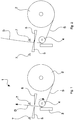
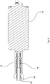
- the printing apparatus 1 may comprise, in particular, a path for feeding a continuous strip S of paper coming from the magazine (in this case a strip S unwound from the reel 2) to a cutting zone of the printed document D.
- the printing apparatus 1 may comprise, in particular, a printing device for printing a document on the strip of paper that advances (unwound from the reel 2).
- the printing device may comprise, for example, a printing head 3 (thermal, inkjet or other) arranged along the path of the paper strip S for printing at least on a first face of the paper (for example a thermally sensitive face).
- a thermal printing head 3 is arranged, but it is possible to provide for the use of an ink jet printing device or of yet another type of printing device.
- a printing roller 4 (paper dragging roller) opposite the printing head 3 may be operationally associated with the printing head 3.
- the printing roller 4 may operate in contact with a second face of the paper (opposite the first printable face).
- the path of the strip S of paper passes, in particular, between the printing head 3 and the printing roller 4.
- the printing roller 4 may be controlled (by a programmable electronic controller, which is not illustrated) in cooperation with the printing head 3, to advance the strip S in a coordinated manner during the step of printing the document D.
- the printing apparatus 1 may comprise, in particular, a cutting device for separating the printed document D from the rest of the strip S when the document D is (stationary) in a cutting zone ( figure 2 ).
- the cutting device may comprise, for example, a motor-driven movable blade 5 cooperating with a stationary blade 6.
- the cutting device may be arranged for adopting at least a first (rest, figures 1 , 3 , 4 ) configuration and at least a second (cutting or work, figures 2 , 5 ) configuration.
- first configuration the movable blade 5 is retracted and distant from the stationary blade 6, leaving free (between the blade 5 and the blade 6) a space for the passage of the printed document D to the cutting zone where the printed document D stops to be separated from the rest of the strip S.
- the movable blade 5 is advanced and partially overlaps the stationary blade 6, obstructing the aforesaid space (between the blade 5 and the blade 6).
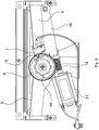
- the printing apparatus 1 may comprise, in particular, sensor means 7 arranged for signalling when the cutting device is in the first (rest) configuration and/or for signalling when the cutting device is in the second (cutting) configuration.
- the sensor means 7 may comprise, as in the embodiment in figures 4 and 5 , a first switch that opens or closes when the cutting device is in the second configuration.
- the sensor means 7 may comprise, as in the embodiment in figures 4 and 5 , a second switch that opens or closes when the cutting device is in the second configuration.
- the second switch may be arranged, in particular, for emitting a signal (for example a closed or open switch electric signal) after the cutting device has separated a document D from the rest of the strip S and before the cutting device returns to a configuration (for example the first rest configuration) that is suitable for permitting the advancement of the strip S for printing a new document D through the space between the blades 5 and 6.
- a signal for example a closed or open switch electric signal
- the first switch may be arranged, in particular, for emitting a signal (for example a closed or open switch electric signal) at the moment in which the cutting device, after separating a document D from the rest of the strip S, has returned to a configuration (for example the first rest configuration) that is suitable for enabling the strip S to advance for the printing of a new document D.
- a signal for example a closed or open switch electric signal
- the cutting device may comprise a first element 8 with rotary motion and a second element 9 with reciprocal motion that receives the motion from the first element 8.
- the second element 9 carries the movable blade 5.
- the first element 8 may be connected to the second element 9 by a mechanism that transforms rotary motion into reciprocal motion, for example a mechanism of the crank and slotted link type with a rocker arm 10 (as in this embodiment), of the connecting rod and crank type or yet another type.
- the cutting device may comprise, as in the embodiments of figures 3 to 9 , an (electric) motor 11 having a rotor connected (coaxially) to a worm screw 12 connected mechanically to the first rotating element 8.
- the sensor means 7 may be operationally associated with the first element 8 (as in this embodiment) and/or with the second element 9 and/or directly with the movable blade 5.
- the sensor means 7 may comprise an elastic element 13 (for example in the shape of an arm) engaged with a cam profile 14 arranged on the first element 8.
- the elastic element 13 may act, as in this case, on a button of an electric contact.
- the sensor means 7 comprises at least one presence or proximity sensor (a switch).
- the sensor means 7 comprises at least one sensor of mechanical type (a switch). It is nevertheless possible to provide for the use of other types of sensor, for example at least one sensor of optical type, of magnetic type, of ultrasound type, etc, which is able to detect when the cutting device is in the first and/or in the second configuration.
- the printing apparatus 1 may comprise, in particular, the aforesaid control means (programmable electronic controller), comprising for example at least one electronic card connected to sensors and actuators of the printing apparatus.
- control means programmable electronic controller
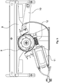
- the sensor means 7 that detects the two configurations (paper path free and paper path occupied) of the cutting device comprises a single (presence or proximity, in particular switch) sensor.
- the sensor may comprise an elastic element 13 (for example in the shape of an arm) engaged with a shaped portion of the first element 8, for example a cam profile 14 arranged on the first element 8.
- the cam profile 14 may be shaped, as in the embodiment of figure 3 , in such a manner as to induce a transition in the sensor (switch) when the cutting device arrives at the first rest configuration (paper path free) and a transition when it arrives at the second cutting configuration (paper path occupied).
- Each transition may comprise, in particular, a transition of the switch from ON to OFF or, vice versa, from OFF to ON.
- the cam profile 14 of the embodiment in figure 3 may have, in particular, a first (greater) diameter for a zone of the profile with an angular size of about half a revolution and a second diameter (less than the first) for the remaining angular size of half a revolution.
- the single sensor In use, when the cutting device reaches the cutting configuration (with the blade 5 advanced that occupies the passage of the paper), the single sensor has a transition that is used as a signal (for the control means) indicating that the cutting configuration has been reached. When the cutting device returns to the rest configuration (with the blade 5 retracted that does not occupy the passage of the paper), the single sensor has another transition that is used as a signal indicating that the rest configuration has been reached.
- an unlocking device for unlocking the cutting device, in particular unlocking a jam of the blade 5.
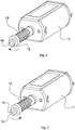
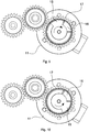
- the rotor of the motor 11 may be reversible with rotation in one direction, for driving the blade 5 in case of normal operation ("forward" rotation, figures 6 and 9 ), and a rotation in the opposite direction (“backward” rotation, figures 7 and 10 ), unlocking the blade, in the case of locking of the blade 5, for example due to jamming.
- the unlocking device may comprise, as in these embodiments, a (reversible) mechanism that connects the rotor of the motor 11 to the blade 5.
- the mechanism may have, in particular, at least a first portion 15 connected (directly) to the rotor and at least one second portion 16 connected (indirectly) to the blade 5.
- the first portion 15 may be coupled (by obstacle, direct contact, or by a kinematic chain) with the second portion 16, whereby the motion can be transmitted to the blade 5.
- the rotor of the motor 11 may be rotated in the opposite direction (backward rotation), by the programmable electronic controller.
- the first portion 15 of the mechanism may be decoupled from the second portion 16, such that the rotor does not drive the second portion 16 and thus the motion is not transmitted to the blade 5.
- the rotor may rotate freely, without obstacle from the second portion 16, without substantially transmitting force to the blade 5, so as to acquire kinetic energy that will be exploited to resolve the jam of the blade 5.
- the first portion 15 couples (by obstacle, in a shock relationship) with the second portion 16, in order that the rotor can also rotate the second portion 16 and thus the (retrograde) motion is transmitted to the blade 5.
- the aforesaid free initial portion (without obstacle or abutment against the second portion 16), during which the rotor can acquire kinetic energy, may extend angularly, in particular, by an angle of at least 5° (sexagesimal degrees), or anyway by an angle of a size that is such as to acquire sufficiently great kinetic energy to generate an impact of the first portion 15 against the second portion 16 that is able to unlock the blade 5.
- the aforesaid initial portion may extend, for example, by an angle of at least 10°, or 20°, or 30°, or 45°, or 90°, or 180°.
- the sensor means 7, which is arranged for detecting the operating configuration of the cutting device, may also be suitable for detecting a situation of locking of the blade, for example a situation in which the blade 5 remains stationary in an advanced position without being able to move back to a rest position.
- the mechanism that connects the motor 11 to the blade 5 may comprise, as said, at least one wheel gear, for example a worm screw 12 (embodiment in figures 6 to 8 ), a straight cylindrical wheel 17 (embodiments in figures 9 to 14 ), a bevel wheel, etc, mounted on a rotating shaft, for example on the rotor of the motor 11, with the interposition of a bearing 18, for example a sliding bearing, mounted (by friction) on the aforesaid shaft.
- a wheel gear for example a worm screw 12 (embodiment in figures 6 to 8 ), a straight cylindrical wheel 17 (embodiments in figures 9 to 14 ), a bevel wheel, etc, mounted on a rotating shaft, for example on the rotor of the motor 11, with the interposition of a bearing 18, for example a sliding bearing, mounted (by friction) on the aforesaid shaft.
- the first portion 15 and the second portion 16 may be, as in these embodiments, integral, respectively, with the bearing 18 and with the wheel gear (12 or 17).
- the bearing 18 may be made of a material with a low friction coefficient, for example of plastics (PTFE), metal (tin-based alloy), etc.
- the wheel gear 12 or 17 may be made of plastics, metal or another material.
- the first portion 15 and/or the second portion 16 may be made of plastics, metal or another material.
- the first portion 15 may comprise, as in these embodiments, at least one first tooth with two opposite sides, each of which engages the second portion 16.
- a side of the first tooth engages the second portion 16 (as an abutment or obstacle) during the forward rotation ( figures 6 and 9 ), whilst the other side of the first tooth engages the second portion 16 (as an abutment or obstacle) during the backward rotation ( figures 7 and 10 ).
- the second portion 16 may comprise, as in these embodiments, at least one second tooth with two opposite sides, each of which engages the first portion 15.
- one side of the second tooth engages the first portion 15 (in an abutment or obstacle relationship) during the forward rotation ( figures 6 and 9 ), whilst the other side of the second tooth engages the first portion 15 (in an abutment or obstacle relationship) during the backward rotation ( figures 7 and 10 ).
- the first portion 15 comprises a tooth and the second portion 16 comprises a tooth.
- the first portion 15 comprises a pair of teeth and the second portion 16 comprises a pair of teeth, in which the teeth of one portion are inserted into the spaces comprised between the teeth of the other portion.
- first portion 15 rotates freely, without being hindered by the second portion 16, as the first portion 15 and the second portion 16 are not mutually engaged (in an abutment or obstacle relationship).
- the first portion 15 and the second portion 16 may be coaxial with one another and be arranged at a certain reciprocal angular distance.
- This angular distance between the first portion 15 and the second portion 16 may enable, at the start of the backward rotation of the rotor, a rotation portion to be obtained in which the first portion 15 is not engaged with the second portion 16, so the motion transmitting mechanism is momentaneously interrupted (for at least 5° of rotation of the rotor) and thus the blade 5 does not substantially receive force from the rotor.
- the first portion 16 may comprise, in particular, first engagement means and the second portion may comprise, in particular, second engagement means.
- the first engagement means may be engaged (in an abutment or obstacle relationship) against a first side of the second engagement means for transmitting the aforesaid forward rotation.
- the first engagement means may be engaged (in an abutment or obstacle relationship) against a second side (opposite the aforesaid first side) of the second engagement means for transmitting the aforesaid backward rotation.
- the first portion 15 may comprise, as in these embodiments, a shaft portion.
- the second portion 16 may comprise, as in these embodiments, a hub portion that is coaxial with the aforesaid shaft portion.
- the first portion 15 may comprise, as in these embodiments, a portion that is rotatable around a rotation axis coinciding with an axis of the rotor of the motor 11.
- the first portion 15 may comprise, as in these embodiments, a rotatable portion that is coaxial with a rotatable portion of the second portion 16.
- the first portion 15 and the second portion 16 work by obstacle and are substantially subjected to a cutting force, with the sides of a portion that adhere to the sides of the other portion, changing sides alternatingly according to the rotating direction of the rotor of the motor 11.
- the blade 5 unlocking device may comprise, as in these embodiments, coupling means between a shaft portion and a hub portion.
- Such coupling means may work, in particular, by obstacle, allowing in a retrograde rotation portion of the shaft portion the coupling means to be disconnected in order that the shaft portion can accumulate kinetic energy.
- the aforesaid coupling means in the embodiments disclosed here, comprises two portions 15 and 16 in the form of protruding teeth that engage one another. It is possible to provide for the use of other coupling means, for example in the form of tab means, grooved profile means, etc.
- the blade 5 unlocking device is applied to a cutting device with a motion transmitting mechanism that comprises a worm screw 12.
- the blade 5 unlocking device is applied to a cutting device with a motion transmitting mechanism that comprises a set of cylindrical wheel gears with straight teeth. It is possible to arrange an unlocking device for unlocking the blade also in other types of cutting devices that are suitable for separating printed documents from a continuous strip in printing apparatuses for payment slips, receipts, tickets, etc.
- the control means operates in such a manner as to perform the following operations.
- the printing apparatus 1 prints a document D on the strip.
- the printed document reaches the cutting zone.
- the cutting device separates the document D (situated in the cutting zone) from the rest of the strip S.
- the sensor means 7 signals to the control means that the blade 5 has not returned to the rest configuration.
- the control means is programmed to reverse the rotating direction of the motor 11 in response to a signal received from the sensor means.
- the rotor of the motor 11 rotates backwards without obstacles by a significant free rotation portion (not less than at least 5°, or 10°, or 30°, or 45°, or 90°, or 180°), until the first portion 15 encounters the second portion 16 (on the opposite side), re-establishing the mechanical connection between the motor 11 and the jammed blade 5.
- a significant free rotation portion not less than at least 5°, or 10°, or 30°, or 45°, or 90°, or 180°
- the printing apparatus 1 may comprise, in particular, programme instructions that are implementable on this programmable controller to run the following steps of a printing method: printing a document on a strip that advances; separating the document from the strip by a cutting device; detecting when the cutting device is in a locked configuration (jam of the blade); driving the cutting device in a reverse manner to solve the lock of the cutting device.
- kinematic motions Some embodiments of kinematic motions have now been disclosed that connect the motor to the blade driven by the motor and some embodiments have now been disclosed of the unlocking devices for unlocking the jam of the blade. It is nevertheless possible to provide other embodiments that are not illustrated of kinematic motions for transferring the kinetic energy of the motor to the blade, for example other types of gear transmissions (other than those disclosed before) or transmissions with mechanical members other than gears such as belts, pulleys, chains, levers, connecting rods etc.
- blade unlocking devices that are arranged for temporarily removing the mechanical connection between the motor and the blade in the initial step of the retrograde motion of the motor to acquire sufficient kinetic energy in order that, when the connection is restored after the initial step of the retrograde motion, a shock is generated that is able to remove the jam: these other embodiments of blade unlocking devices may comprise, in particular, obstacle engaging means associated with two members of the kinematic motion that are other than those already disclosed, for example two non-rotating members, or a pulley and a timing belt, or a pinion and a transmission chain, etc.
Landscapes
- Life Sciences & Earth Sciences (AREA)
- Forests & Forestry (AREA)
- Engineering & Computer Science (AREA)
- Mechanical Engineering (AREA)
- Handling Of Sheets (AREA)
Claims (11)
- Druckvorrichtung (1) mit:- einer Druckeinrichtung, die dazu ausgebildet ist, ein Dokument (D) auf einem Streifen (S) zu drucken, der sich entlang eines Weges vorwärts bewegt- einem Schneidmittel (5), das dazu ausgebildet ist, das Dokument (D) von dem Streifen (S) zu trennen;- einem reversiblen Rotor mit einer Vorwärtsdrehung, um das Schneidmittel (5) bei normaler Betriebsweise anzutreiben, und mit einer Rückwärtsdrehung, um das Schneidmittel im Falle der Blockierung des Schneidmittels (5) zum Beispiel durch Festsitzen wieder zu lösen;- gekennzeichnet durch einen Mechanismus, der den Rotor mit dem Schneidmittel (5) verbindet, wobei der Mechanismus wenigstens einen ersten Teil (15) aufweist, der mit dem Motor verbunden ist und wenigstens einen zweiten Teil (16), der mit dem Schneidmittel (5) verbunden ist;wobei:- bei der Vorwärtsdrehung der erste Teil (15) mit dem zweiten Teil (16) gekoppelt ist, wodurch die Bewegung zu dem Schneidmittel (5) übertragen wird;- in einem anfänglichen Teil der Rückwärtsdrehung der erste Teil (15) von dem zweiten Teil (16) entkoppelt ist, wodurch der Rotor den zweiten Teil (16) nicht antreibt und die Bewegung nicht auf das Schneidmittel (5) übertragen wird;- bei weiterer Rückwärtsdrehung nach dem anfänglichen Teil der Rückwärtsdrehung der erste Teil (15) mit dem zweiten Teil (16) gekoppelt ist, wodurch der Rotor auch den zweiten Teil (16) antreibt und dann die Bewegung auf das Schneidmittel (5) übertragen wird;wobei ein Teil der Rückwärtsdrehung sich über einen Winkel von wenigstens 180° erstreckt, um so eine Einwirkung des ersten Teils (15) gegen den zweiten Teil (16) zu bestimmen, die ausreichend ist, um das Schneidmittel (5) freizugeben.
- Vorrichtung nach Anspruch 1, umfassend ein Sensormittel (7) zum Detektieren eines Blockierzustands des Schneidmittels (5).
- Vorrichtung nach irgendeinem der vorhergehenden Ansprüche, bei der der Mechanismus wenigstens einen Zahnrad aufweist, das auf einer drehbaren Welle unter Zwischenlage eines Lagers (18) auf der Welle aufgenommen ist, wobei einer der ersten und zweiten Teile (15; 16) mit dem Lager (18) einstückig ausgebildet ist und der andere mit dem Zahnrad (12; 17).
- Vorrichtung nach Anspruch 3, bei der die drehbare Welle den Rotor umfasst.
- Vorrichtung nach Anspruch 3 oder 4, bei der das wenigstens eine Zahnrad eine Schneckenschraube (12) oder ein gerades zylindrisches Rad (17) aufweist und das Lager (18) ein Gleitlager aufweist.
- Vorrichtung nach irgendeinem der vorhergehenden Ansprüche, bei der der erste Teil (15) wenigstens ein erstes Eingriffsmittel aufweist, und der zweite Teil (16) ein zweites Eingriffsmittel aufweist, wobei das erste Eingriffsmittel selektiv mit einer ersten Seite des zweiten Eingriffsmittels im Eingriff ist, um die Vorwärtsdrehung durch ein Hindernis zu übertragen, oder mit einer zweiten Seite, die gegenüber der ersten Seite des zweiten Eingriffsmittels ist, um die Rückwärtsdrehung durch ein Hindernis zu übertragen.
- Vorrichtung nach irgendeinem der vorhergehenden Ansprüche, bei der der erste Teil (15) einen Wellenteil aufweist, und bei der der zweite Teil (16) einen Nabenteil aufweist, der koaxial mit dem Wellenteil ist.
- Vorrichtung nach irgendeinem der vorhergehenden Ansprüche, bei der der erste Teil (15) einen Bereich aufweist, der um eine Drehachse drehbar ist, die mit der Achse des Rotors zusammenfällt.
- Vorrichtung nach irgendeinem der vorhergehenden Ansprüche, bei der der erste Teil (15) einen drehbaren Bereich aufweist, der koaxial mit einem drehbaren Bereich des zweiten Teils (16) ist.
- Vorrichtung nach irgendeinem der vorhergehenden Ansprüche, bei der der erste Teil (15) wenigstens einen ersten Zahn mit zwei gegenüberliegenden Seiten aufweist, von denen jeder im Eingriff mit dem zweiten Teil (16) ist, wobei eine Seite in der Vorwärtsdrehung und die andere Seite in der Rückwärtsdrehung ist, und/oder bei der der zweite Teil (16) wenigstens einen zweiten Zahn mit zwei gegenüberliegenden Seiten aufweist, von denen jeder im Eingriff mit dem ersten Teil (15) ist, wobei eine Seite in der Vorwärtsdrehung und die andere Seite in der Rückwärtsdrehung ist.
- Vorrichtung nach irgendeinem der vorhergehenden Ansprüche, bei der der Mechanismus ein Getriebe aufweist, das eine kontinuierliche Drehbewegung des Rotors in eine hin- und hergehende Bewegung einer Schneide des Schneidmittels umsetzt.
Applications Claiming Priority (2)
| Application Number | Priority Date | Filing Date | Title |
|---|---|---|---|
| ITUB20151078 | 2015-06-10 | ||
| PCT/IB2016/053345 WO2016199026A1 (en) | 2015-06-10 | 2016-06-08 | Printing apparatus |
Publications (2)
| Publication Number | Publication Date |
|---|---|
| EP3307497A1 EP3307497A1 (de) | 2018-04-18 |
| EP3307497B1 true EP3307497B1 (de) | 2019-08-28 |
Family
ID=54347612
Family Applications (1)
| Application Number | Title | Priority Date | Filing Date |
|---|---|---|---|
| EP16739558.1A Active EP3307497B1 (de) | 2015-06-10 | 2016-06-08 | Druckvorrichtung |
Country Status (6)
| Country | Link |
|---|---|
| US (1) | US10272702B2 (de) |
| EP (1) | EP3307497B1 (de) |
| CN (1) | CN107709022B (de) |
| ES (1) | ES2758367T3 (de) |
| RU (1) | RU2721693C2 (de) |
| WO (1) | WO2016199026A1 (de) |
Families Citing this family (3)
| Publication number | Priority date | Publication date | Assignee | Title |
|---|---|---|---|---|
| US11241895B2 (en) * | 2019-06-13 | 2022-02-08 | Bixolon Co., Ltd. | Paper cutting device for kiosk printer and kiosk printer equipped with the same |
| JP7443770B2 (ja) | 2020-01-07 | 2024-03-06 | コニカミノルタ株式会社 | 用紙断裁装置 |
| PL3988486T3 (pl) * | 2020-10-21 | 2023-12-27 | Fameccanica.Data S.P.A. | Aparat i sposób do wydawania sekcji dwustronnej taśmy klejącej |
Family Cites Families (6)
| Publication number | Priority date | Publication date | Assignee | Title |
|---|---|---|---|---|
| JP3433995B2 (ja) * | 1993-12-28 | 2003-08-04 | シチズン時計株式会社 | カッター装置およびそれを備えたプリンタ装置 |
| CN1093800C (zh) * | 1995-09-19 | 2002-11-06 | 精工爱普生株式会社 | 带有自动切纸器的打印装置 |
| US5971639A (en) * | 1996-11-11 | 1999-10-26 | Samsung Electro-Mechanics Co., Ltd. | Paper cutting apparatus in a small-sized printer |
| TW371640B (en) * | 1997-04-09 | 1999-10-11 | Seiko Epson Corp | Automatic cutting device, method for controlling the same and printer using thereof |
| US6547464B1 (en) * | 1999-12-01 | 2003-04-15 | Diebòld, Incorporated | Automated transaction machine printer |
| JP5347785B2 (ja) * | 2009-07-13 | 2013-11-20 | セイコーエプソン株式会社 | 切断装置及び切断装置付きプリンター |
-
2016
- 2016-06-08 EP EP16739558.1A patent/EP3307497B1/de active Active
- 2016-06-08 CN CN201680032992.3A patent/CN107709022B/zh active Active
- 2016-06-08 US US15/577,576 patent/US10272702B2/en active Active
- 2016-06-08 ES ES16739558T patent/ES2758367T3/es active Active
- 2016-06-08 RU RU2017145784A patent/RU2721693C2/ru active
- 2016-06-08 WO PCT/IB2016/053345 patent/WO2016199026A1/en not_active Ceased
Non-Patent Citations (1)
| Title |
|---|
| None * |
Also Published As
| Publication number | Publication date |
|---|---|
| CN107709022B (zh) | 2021-06-01 |
| CN107709022A (zh) | 2018-02-16 |
| RU2017145784A (ru) | 2019-07-10 |
| RU2017145784A3 (de) | 2019-10-02 |
| WO2016199026A1 (en) | 2016-12-15 |
| RU2721693C2 (ru) | 2020-05-21 |
| US10272702B2 (en) | 2019-04-30 |
| EP3307497A1 (de) | 2018-04-18 |
| US20180134052A1 (en) | 2018-05-17 |
| ES2758367T3 (es) | 2020-05-05 |
Similar Documents
| Publication | Publication Date | Title |
|---|---|---|
| CN105730031B (zh) | 切割器刀片驱动机构、切割器以及打印机 | |
| EP3307497B1 (de) | Druckvorrichtung | |
| JP5941657B2 (ja) | カッター付きプリンタ | |
| CN101909895B (zh) | 打印机 | |
| US9522552B2 (en) | Cutter and printer | |
| CN103909745B (zh) | 打印机装置 | |
| EP2727736B1 (de) | Drucker mit Präsentationsteil und Schneidvorrichtung mit gemeinsamer Bewegung | |
| JP4218710B2 (ja) | クラッチ装置、被記録材給送装置、記録装置 | |
| CN106994840B (zh) | 一种带故障自动修复功能的打印机及其控制方法 | |
| EP3046770B1 (de) | Druckmechanismus | |
| EP2727737A1 (de) | Druckervorrichtung | |
| CN107538934B (zh) | 印刷装置及切断装置 | |
| CN111522215B (zh) | 显影盒及图像形成装置 | |
| EP2927006B1 (de) | Drucker | |
| US9731524B2 (en) | Cutter blade moving mechanism, cutter, and printer | |
| JP7068571B2 (ja) | プリンタ | |
| JP6452328B2 (ja) | プリンタ装置 | |
| JP6529729B2 (ja) | プリンタ装置及びプリンタ装置の操作方法 | |
| WO2013136920A1 (en) | Printer apparatus and method of controlling printer apparatus | |
| JPH04223940A (ja) | シリアルプリンタ | |
| JP2009250386A (ja) | クラッチ装置、記録装置 |
Legal Events
| Date | Code | Title | Description |
|---|---|---|---|
| STAA | Information on the status of an ep patent application or granted ep patent |
Free format text: STATUS: THE INTERNATIONAL PUBLICATION HAS BEEN MADE |
|
| PUAI | Public reference made under article 153(3) epc to a published international application that has entered the european phase |
Free format text: ORIGINAL CODE: 0009012 |
|
| STAA | Information on the status of an ep patent application or granted ep patent |
Free format text: STATUS: REQUEST FOR EXAMINATION WAS MADE |
|
| 17P | Request for examination filed |
Effective date: 20180110 |
|
| AK | Designated contracting states |
Kind code of ref document: A1 Designated state(s): AL AT BE BG CH CY CZ DE DK EE ES FI FR GB GR HR HU IE IS IT LI LT LU LV MC MK MT NL NO PL PT RO RS SE SI SK SM TR |
|
| AX | Request for extension of the european patent |
Extension state: BA ME |
|
| DAV | Request for validation of the european patent (deleted) | ||
| DAX | Request for extension of the european patent (deleted) | ||
| STAA | Information on the status of an ep patent application or granted ep patent |
Free format text: STATUS: EXAMINATION IS IN PROGRESS |
|
| 17Q | First examination report despatched |
Effective date: 20181002 |
|
| GRAP | Despatch of communication of intention to grant a patent |
Free format text: ORIGINAL CODE: EPIDOSNIGR1 |
|
| STAA | Information on the status of an ep patent application or granted ep patent |
Free format text: STATUS: GRANT OF PATENT IS INTENDED |
|
| INTG | Intention to grant announced |
Effective date: 20190319 |
|
| GRAS | Grant fee paid |
Free format text: ORIGINAL CODE: EPIDOSNIGR3 |
|
| GRAA | (expected) grant |
Free format text: ORIGINAL CODE: 0009210 |
|
| STAA | Information on the status of an ep patent application or granted ep patent |
Free format text: STATUS: THE PATENT HAS BEEN GRANTED |
|
| AK | Designated contracting states |
Kind code of ref document: B1 Designated state(s): AL AT BE BG CH CY CZ DE DK EE ES FI FR GB GR HR HU IE IS IT LI LT LU LV MC MK MT NL NO PL PT RO RS SE SI SK SM TR |
|
| REG | Reference to a national code |
Ref country code: GB Ref legal event code: FG4D |
|
| REG | Reference to a national code |
Ref country code: CH Ref legal event code: EP |
|
| REG | Reference to a national code |
Ref country code: AT Ref legal event code: REF Ref document number: 1171829 Country of ref document: AT Kind code of ref document: T Effective date: 20190915 |
|
| REG | Reference to a national code |
Ref country code: IE Ref legal event code: FG4D |
|
| REG | Reference to a national code |
Ref country code: DE Ref legal event code: R096 Ref document number: 602016019447 Country of ref document: DE |
|
| REG | Reference to a national code |
Ref country code: NL Ref legal event code: MP Effective date: 20190828 |
|
| REG | Reference to a national code |
Ref country code: LT Ref legal event code: MG4D |
|
| PG25 | Lapsed in a contracting state [announced via postgrant information from national office to epo] |
Ref country code: NO Free format text: LAPSE BECAUSE OF FAILURE TO SUBMIT A TRANSLATION OF THE DESCRIPTION OR TO PAY THE FEE WITHIN THE PRESCRIBED TIME-LIMIT Effective date: 20191128 Ref country code: LT Free format text: LAPSE BECAUSE OF FAILURE TO SUBMIT A TRANSLATION OF THE DESCRIPTION OR TO PAY THE FEE WITHIN THE PRESCRIBED TIME-LIMIT Effective date: 20190828 Ref country code: NL Free format text: LAPSE BECAUSE OF FAILURE TO SUBMIT A TRANSLATION OF THE DESCRIPTION OR TO PAY THE FEE WITHIN THE PRESCRIBED TIME-LIMIT Effective date: 20190828 Ref country code: BG Free format text: LAPSE BECAUSE OF FAILURE TO SUBMIT A TRANSLATION OF THE DESCRIPTION OR TO PAY THE FEE WITHIN THE PRESCRIBED TIME-LIMIT Effective date: 20191128 Ref country code: FI Free format text: LAPSE BECAUSE OF FAILURE TO SUBMIT A TRANSLATION OF THE DESCRIPTION OR TO PAY THE FEE WITHIN THE PRESCRIBED TIME-LIMIT Effective date: 20190828 Ref country code: HR Free format text: LAPSE BECAUSE OF FAILURE TO SUBMIT A TRANSLATION OF THE DESCRIPTION OR TO PAY THE FEE WITHIN THE PRESCRIBED TIME-LIMIT Effective date: 20190828 Ref country code: PT Free format text: LAPSE BECAUSE OF FAILURE TO SUBMIT A TRANSLATION OF THE DESCRIPTION OR TO PAY THE FEE WITHIN THE PRESCRIBED TIME-LIMIT Effective date: 20191230 Ref country code: SE Free format text: LAPSE BECAUSE OF FAILURE TO SUBMIT A TRANSLATION OF THE DESCRIPTION OR TO PAY THE FEE WITHIN THE PRESCRIBED TIME-LIMIT Effective date: 20190828 |
|
| PG25 | Lapsed in a contracting state [announced via postgrant information from national office to epo] |
Ref country code: GR Free format text: LAPSE BECAUSE OF FAILURE TO SUBMIT A TRANSLATION OF THE DESCRIPTION OR TO PAY THE FEE WITHIN THE PRESCRIBED TIME-LIMIT Effective date: 20191129 Ref country code: AL Free format text: LAPSE BECAUSE OF FAILURE TO SUBMIT A TRANSLATION OF THE DESCRIPTION OR TO PAY THE FEE WITHIN THE PRESCRIBED TIME-LIMIT Effective date: 20190828 Ref country code: LV Free format text: LAPSE BECAUSE OF FAILURE TO SUBMIT A TRANSLATION OF THE DESCRIPTION OR TO PAY THE FEE WITHIN THE PRESCRIBED TIME-LIMIT Effective date: 20190828 Ref country code: RS Free format text: LAPSE BECAUSE OF FAILURE TO SUBMIT A TRANSLATION OF THE DESCRIPTION OR TO PAY THE FEE WITHIN THE PRESCRIBED TIME-LIMIT Effective date: 20190828 Ref country code: IS Free format text: LAPSE BECAUSE OF FAILURE TO SUBMIT A TRANSLATION OF THE DESCRIPTION OR TO PAY THE FEE WITHIN THE PRESCRIBED TIME-LIMIT Effective date: 20191228 |
|
| REG | Reference to a national code |
Ref country code: AT Ref legal event code: MK05 Ref document number: 1171829 Country of ref document: AT Kind code of ref document: T Effective date: 20190828 |
|
| PG25 | Lapsed in a contracting state [announced via postgrant information from national office to epo] |
Ref country code: TR Free format text: LAPSE BECAUSE OF FAILURE TO SUBMIT A TRANSLATION OF THE DESCRIPTION OR TO PAY THE FEE WITHIN THE PRESCRIBED TIME-LIMIT Effective date: 20190828 |
|
| PG25 | Lapsed in a contracting state [announced via postgrant information from national office to epo] |
Ref country code: AT Free format text: LAPSE BECAUSE OF FAILURE TO SUBMIT A TRANSLATION OF THE DESCRIPTION OR TO PAY THE FEE WITHIN THE PRESCRIBED TIME-LIMIT Effective date: 20190828 Ref country code: DK Free format text: LAPSE BECAUSE OF FAILURE TO SUBMIT A TRANSLATION OF THE DESCRIPTION OR TO PAY THE FEE WITHIN THE PRESCRIBED TIME-LIMIT Effective date: 20190828 Ref country code: EE Free format text: LAPSE BECAUSE OF FAILURE TO SUBMIT A TRANSLATION OF THE DESCRIPTION OR TO PAY THE FEE WITHIN THE PRESCRIBED TIME-LIMIT Effective date: 20190828 Ref country code: RO Free format text: LAPSE BECAUSE OF FAILURE TO SUBMIT A TRANSLATION OF THE DESCRIPTION OR TO PAY THE FEE WITHIN THE PRESCRIBED TIME-LIMIT Effective date: 20190828 Ref country code: PL Free format text: LAPSE BECAUSE OF FAILURE TO SUBMIT A TRANSLATION OF THE DESCRIPTION OR TO PAY THE FEE WITHIN THE PRESCRIBED TIME-LIMIT Effective date: 20190828 |
|
| REG | Reference to a national code |
Ref country code: ES Ref legal event code: FG2A Ref document number: 2758367 Country of ref document: ES Kind code of ref document: T3 Effective date: 20200505 |
|
| PG25 | Lapsed in a contracting state [announced via postgrant information from national office to epo] |
Ref country code: IS Free format text: LAPSE BECAUSE OF FAILURE TO SUBMIT A TRANSLATION OF THE DESCRIPTION OR TO PAY THE FEE WITHIN THE PRESCRIBED TIME-LIMIT Effective date: 20200224 Ref country code: SK Free format text: LAPSE BECAUSE OF FAILURE TO SUBMIT A TRANSLATION OF THE DESCRIPTION OR TO PAY THE FEE WITHIN THE PRESCRIBED TIME-LIMIT Effective date: 20190828 Ref country code: CZ Free format text: LAPSE BECAUSE OF FAILURE TO SUBMIT A TRANSLATION OF THE DESCRIPTION OR TO PAY THE FEE WITHIN THE PRESCRIBED TIME-LIMIT Effective date: 20190828 Ref country code: SM Free format text: LAPSE BECAUSE OF FAILURE TO SUBMIT A TRANSLATION OF THE DESCRIPTION OR TO PAY THE FEE WITHIN THE PRESCRIBED TIME-LIMIT Effective date: 20190828 |
|
| REG | Reference to a national code |
Ref country code: DE Ref legal event code: R097 Ref document number: 602016019447 Country of ref document: DE |
|
| PLBE | No opposition filed within time limit |
Free format text: ORIGINAL CODE: 0009261 |
|
| STAA | Information on the status of an ep patent application or granted ep patent |
Free format text: STATUS: NO OPPOSITION FILED WITHIN TIME LIMIT |
|
| PG2D | Information on lapse in contracting state deleted |
Ref country code: IS |
|
| 26N | No opposition filed |
Effective date: 20200603 |
|
| PG25 | Lapsed in a contracting state [announced via postgrant information from national office to epo] |
Ref country code: SI Free format text: LAPSE BECAUSE OF FAILURE TO SUBMIT A TRANSLATION OF THE DESCRIPTION OR TO PAY THE FEE WITHIN THE PRESCRIBED TIME-LIMIT Effective date: 20190828 |
|
| PG25 | Lapsed in a contracting state [announced via postgrant information from national office to epo] |
Ref country code: MC Free format text: LAPSE BECAUSE OF FAILURE TO SUBMIT A TRANSLATION OF THE DESCRIPTION OR TO PAY THE FEE WITHIN THE PRESCRIBED TIME-LIMIT Effective date: 20190828 |
|
| REG | Reference to a national code |
Ref country code: CH Ref legal event code: PL |
|
| GBPC | Gb: european patent ceased through non-payment of renewal fee |
Effective date: 20200608 |
|
| PG25 | Lapsed in a contracting state [announced via postgrant information from national office to epo] |
Ref country code: LU Free format text: LAPSE BECAUSE OF NON-PAYMENT OF DUE FEES Effective date: 20200608 |
|
| REG | Reference to a national code |
Ref country code: BE Ref legal event code: MM Effective date: 20200630 |
|
| PG25 | Lapsed in a contracting state [announced via postgrant information from national office to epo] |
Ref country code: IE Free format text: LAPSE BECAUSE OF NON-PAYMENT OF DUE FEES Effective date: 20200608 Ref country code: GB Free format text: LAPSE BECAUSE OF NON-PAYMENT OF DUE FEES Effective date: 20200608 Ref country code: LI Free format text: LAPSE BECAUSE OF NON-PAYMENT OF DUE FEES Effective date: 20200630 Ref country code: CH Free format text: LAPSE BECAUSE OF NON-PAYMENT OF DUE FEES Effective date: 20200630 |
|
| PG25 | Lapsed in a contracting state [announced via postgrant information from national office to epo] |
Ref country code: BE Free format text: LAPSE BECAUSE OF NON-PAYMENT OF DUE FEES Effective date: 20200630 |
|
| PG25 | Lapsed in a contracting state [announced via postgrant information from national office to epo] |
Ref country code: MT Free format text: LAPSE BECAUSE OF FAILURE TO SUBMIT A TRANSLATION OF THE DESCRIPTION OR TO PAY THE FEE WITHIN THE PRESCRIBED TIME-LIMIT Effective date: 20190828 Ref country code: CY Free format text: LAPSE BECAUSE OF FAILURE TO SUBMIT A TRANSLATION OF THE DESCRIPTION OR TO PAY THE FEE WITHIN THE PRESCRIBED TIME-LIMIT Effective date: 20190828 |
|
| PG25 | Lapsed in a contracting state [announced via postgrant information from national office to epo] |
Ref country code: MK Free format text: LAPSE BECAUSE OF FAILURE TO SUBMIT A TRANSLATION OF THE DESCRIPTION OR TO PAY THE FEE WITHIN THE PRESCRIBED TIME-LIMIT Effective date: 20190828 |
|
| PGFP | Annual fee paid to national office [announced via postgrant information from national office to epo] |
Ref country code: DE Payment date: 20250627 Year of fee payment: 10 |
|
| PGFP | Annual fee paid to national office [announced via postgrant information from national office to epo] |
Ref country code: FR Payment date: 20250625 Year of fee payment: 10 |
|
| PGFP | Annual fee paid to national office [announced via postgrant information from national office to epo] |
Ref country code: ES Payment date: 20250701 Year of fee payment: 10 |
|
| PGFP | Annual fee paid to national office [announced via postgrant information from national office to epo] |
Ref country code: IT Payment date: 20250625 Year of fee payment: 10 |