EP3307461B1 - Heizsystem für vorrichtung zur handhabung von metallschmelze - Google Patents
Heizsystem für vorrichtung zur handhabung von metallschmelze Download PDFInfo
- Publication number
- EP3307461B1 EP3307461B1 EP16812124.2A EP16812124A EP3307461B1 EP 3307461 B1 EP3307461 B1 EP 3307461B1 EP 16812124 A EP16812124 A EP 16812124A EP 3307461 B1 EP3307461 B1 EP 3307461B1
- Authority
- EP
- European Patent Office
- Prior art keywords
- heater
- molten metal
- inward facing
- heater assembly
- thermal
- Prior art date
- Legal status (The legal status is an assumption and is not a legal conclusion. Google has not performed a legal analysis and makes no representation as to the accuracy of the status listed.)
- Active
Links
Images


Classifications
-
- H—ELECTRICITY
- H05—ELECTRIC TECHNIQUES NOT OTHERWISE PROVIDED FOR
- H05B—ELECTRIC HEATING; ELECTRIC LIGHT SOURCES NOT OTHERWISE PROVIDED FOR; CIRCUIT ARRANGEMENTS FOR ELECTRIC LIGHT SOURCES, IN GENERAL
- H05B6/00—Heating by electric, magnetic or electromagnetic fields
- H05B6/02—Induction heating
- H05B6/36—Coil arrangements
- H05B6/367—Coil arrangements for melting furnaces
-
- B—PERFORMING OPERATIONS; TRANSPORTING
- B22—CASTING; POWDER METALLURGY
- B22D—CASTING OF METALS; CASTING OF OTHER SUBSTANCES BY THE SAME PROCESSES OR DEVICES
- B22D35/00—Equipment for conveying molten metal into beds or moulds
- B22D35/04—Equipment for conveying molten metal into beds or moulds into moulds, e.g. base plates, runners
-
- C—CHEMISTRY; METALLURGY
- C21—METALLURGY OF IRON
- C21B—MANUFACTURE OF IRON OR STEEL
- C21B7/00—Blast furnaces
- C21B7/14—Discharging devices, e.g. for slag
-
- C—CHEMISTRY; METALLURGY
- C21—METALLURGY OF IRON
- C21D—MODIFYING THE PHYSICAL STRUCTURE OF FERROUS METALS; GENERAL DEVICES FOR HEAT TREATMENT OF FERROUS OR NON-FERROUS METALS OR ALLOYS; MAKING METAL MALLEABLE, e.g. BY DECARBURISATION OR TEMPERING
- C21D1/00—General methods or devices for heat treatment, e.g. annealing, hardening, quenching or tempering
- C21D1/06—Surface hardening
- C21D1/09—Surface hardening by direct application of electrical or wave energy; by particle radiation
- C21D1/10—Surface hardening by direct application of electrical or wave energy; by particle radiation by electric induction
-
- F—MECHANICAL ENGINEERING; LIGHTING; HEATING; WEAPONS; BLASTING
- F27—FURNACES; KILNS; OVENS; RETORTS
- F27D—DETAILS OR ACCESSORIES OF FURNACES, KILNS, OVENS OR RETORTS, IN SO FAR AS THEY ARE OF KINDS OCCURRING IN MORE THAN ONE KIND OF FURNACE
- F27D1/00—Casings; Linings; Walls; Roofs
- F27D1/0003—Linings or walls
- F27D1/0006—Linings or walls formed from bricks or layers with a particular composition or specific characteristics
-
- F—MECHANICAL ENGINEERING; LIGHTING; HEATING; WEAPONS; BLASTING
- F27—FURNACES; KILNS; OVENS; RETORTS
- F27D—DETAILS OR ACCESSORIES OF FURNACES, KILNS, OVENS OR RETORTS, IN SO FAR AS THEY ARE OF KINDS OCCURRING IN MORE THAN ONE KIND OF FURNACE
- F27D11/00—Arrangement of elements for electric heating in or on furnaces
- F27D11/02—Ohmic resistance heating
-
- F—MECHANICAL ENGINEERING; LIGHTING; HEATING; WEAPONS; BLASTING
- F27—FURNACES; KILNS; OVENS; RETORTS
- F27D—DETAILS OR ACCESSORIES OF FURNACES, KILNS, OVENS OR RETORTS, IN SO FAR AS THEY ARE OF KINDS OCCURRING IN MORE THAN ONE KIND OF FURNACE
- F27D3/00—Charging; Discharging; Manipulation of charge
- F27D3/14—Charging or discharging liquid or molten material
- F27D3/145—Runners therefor
-
- F—MECHANICAL ENGINEERING; LIGHTING; HEATING; WEAPONS; BLASTING
- F27—FURNACES; KILNS; OVENS; RETORTS
- F27D—DETAILS OR ACCESSORIES OF FURNACES, KILNS, OVENS OR RETORTS, IN SO FAR AS THEY ARE OF KINDS OCCURRING IN MORE THAN ONE KIND OF FURNACE
- F27D99/00—Subject matter not provided for in other groups of this subclass
- F27D99/0001—Heating elements or systems
- F27D99/0006—Electric heating elements or system
-
- H—ELECTRICITY
- H05—ELECTRIC TECHNIQUES NOT OTHERWISE PROVIDED FOR
- H05B—ELECTRIC HEATING; ELECTRIC LIGHT SOURCES NOT OTHERWISE PROVIDED FOR; CIRCUIT ARRANGEMENTS FOR ELECTRIC LIGHT SOURCES, IN GENERAL
- H05B6/00—Heating by electric, magnetic or electromagnetic fields
- H05B6/02—Induction heating
- H05B6/16—Furnaces having endless cores
- H05B6/18—Furnaces having endless cores having melting basin
-
- F—MECHANICAL ENGINEERING; LIGHTING; HEATING; WEAPONS; BLASTING
- F27—FURNACES; KILNS; OVENS; RETORTS
- F27D—DETAILS OR ACCESSORIES OF FURNACES, KILNS, OVENS OR RETORTS, IN SO FAR AS THEY ARE OF KINDS OCCURRING IN MORE THAN ONE KIND OF FURNACE
- F27D99/00—Subject matter not provided for in other groups of this subclass
- F27D99/0001—Heating elements or systems
- F27D99/0006—Electric heating elements or system
- F27D2099/0015—Induction heating
-
- Y—GENERAL TAGGING OF NEW TECHNOLOGICAL DEVELOPMENTS; GENERAL TAGGING OF CROSS-SECTIONAL TECHNOLOGIES SPANNING OVER SEVERAL SECTIONS OF THE IPC; TECHNICAL SUBJECTS COVERED BY FORMER USPC CROSS-REFERENCE ART COLLECTIONS [XRACs] AND DIGESTS
- Y02—TECHNOLOGIES OR APPLICATIONS FOR MITIGATION OR ADAPTATION AGAINST CLIMATE CHANGE
- Y02P—CLIMATE CHANGE MITIGATION TECHNOLOGIES IN THE PRODUCTION OR PROCESSING OF GOODS
- Y02P10/00—Technologies related to metal processing
- Y02P10/25—Process efficiency
Definitions
- This invention pertains to a heating and insulation system for molten metal handling devices, examples of which are troughs, launders and other vessels.
- molten metal such as aluminum, aluminum alloys and others are typically handled and/or contained in various devices, vessels, troughs, launders and other containment and movement/transfer devices.
- Molten metal troughs for example are commonly used to transfer and contain molten metal.
- molten metal contains a significant amount of internal heat
- Supplemental or additional heat can supply heat to and through the refractory of the handling or containment device, and to the molten metal itself.
- the industry has experienced hot spots on the interior surface of the metal handling device (such as a trough) which can cause undesirable issues in the molten metal and on the interior surface of the refractory of the handling device.
- the balancing interest and concern is that the more the heat supply is reduced or buffered to avoid creating hot spots, generally the less energy efficient the process is.
- Past attempts to address this situation have included creating continuous air gaps between the heater element and the refractory body of the handling device; using an expensive higher grade of material that makes the product potentially cost prohibitive; and others.
- WO2012/175911 A1 relates to a metal transfer device which includes a cast trough body, and a filler layer between the trough body and a heater.
- the filler layer comprises a cast refractory material having a high thermal conductivity.
- the present invention is directed to a molten metal handling device as defined in claims 1 and 14.
- Many of the fastening, connection, manufacturing and other means and components utilized in this invention are widely known and used in the field of the invention described, and their exact nature or type is not necessary for an understanding and use of the invention by a person skilled in the art or science; therefore, they will not be discussed in significant detail.
- the various components shown or described herein for any specific application of this invention can be varied or altered as anticipated by this invention and the practice of a specific application or embodiment of any element may already be widely known or used in the art or by persons skilled in the art or science; therefore, each will not be discussed in significant detail.
- Figure 1 is a cross-section view of one example of an embodiment of a handling device heating system contemplated by this invention, illustrating outer casing 116, containment shell 106, heater elements or heater assemblies 107 with heater coils 108 contained therein, and refractory trough body 103 with trough body bottom wall 103a, first side wall 103b and second side wall 103c of trough body 103.
- the trough walls define trough 102.
- Figure 1 further shows the containment shell 106, insulation layers 104 and bottom liner 105.
- Figure 1 illustrates heat 114 being provided to the refractory trough 102 area, which is where the molten metal would receive the heat.
- the heater elements or heater assemblies 107 include heater coils 108 within heater assembly bodies 112.
- Figure 1 shows how the heating elements in this embodiment may include inward faces of the heating elements 107 which have horizontal grooves therein.
- the high temperature heat inducing cement 110 is utilized to fill those grooves between the protruding portions of the heating element bodies to assure the heat transfer is more efficiently provided via conduction without gaps through both the heating element body portions 112 and through the high temperature heat inducing cement 110 placed between the inner facing surfaces 112a of the heating element body portions 112.
- the high temperature heat inducing cement may be used to fill those gaps to provide the face, interface or inner surface desired in that embodiment.
- Heater assemblies for some applications may include vertical grooves (shown in later figures) which may similarly be filled, within the contemplation of this invention.
- the heater elements may be provided with smooth or flat faces, interfaces or inner surfaces, in which case a layer of the high temperature heat inducing cement may be placed between the heating elements and the containment fence, refractory or other next layer in that particular embodiment of the system, all within the contemplation of this invention.
- the containment shell 106 may be comprised of a reinforced fiberglass material ("RFM”) such as a low thermally conductive composite material made of fiberglass fabric embedded in a slurry of silicon carbide manufactured by Pyrotek, Inc., Spokane, WA under its RFM brand.
- RFM reinforced fiberglass material
- the thermal expansion coefficient for example for the Pyrotek-manufactured RFM silicon carbide may be about 4.6 x 10 4 mm/mm- 0 C.
- the containment shell 106 or fence may be made of steel alloys or stainless steel, within the contemplation of embodiments of this invention. While a containment shell 106 is preferable to act as a fence or perimeter barrier to provide some containment in the event molten metal escapes through the refractory, it is not required by all embodiments of this invention.
- the refractory body and/or the interface surface of the one or more heater assemblies tend to separate due to differences in the thermal expansion of the respective materials. It has been found as part of some embodiments of this invention that if the thermal expansion properties of the containment shell are correlated to the thermal expansion properties of one of or both of the refractory body or the one or more heater assemblies, the separation of the containment fence from one of or both of the refractory body or the one or more heater assemblies is reduced. The correlation of the thermal expansion properties will reduce separation during thermal expansion and contraction. This has been experienced in the use of reinforced fiberglass material ("RFM”) as described herein.
- RFM reinforced fiberglass material
- fiberglass when used herein, it may include without limitation, traditional fiberglass matting, or is may preferably include a high temperature leached glass in the form of a flat woven mat that has apertures.
- the apertures in the flat woven mat may be of any geometry, such as square, round, polygonal, or other. In other embodiments an "E" glass grade of cloth may be utilized.
- the additional barriers or layers 104 may be any one or more of a number of different materials depending on the embodiment and application, such as the embodiment illustrated in Figure 1 utilizing an approximate seventy-four percent silicon carbide material, in combination with an approximate thirty-five percent silicon carbide refractory material castable comprising the refractory trough 103.
- the bottom layer or liner 105 may be any one or more different materials, such as a ceramic paper based liner, micro-pore board or others, with no one in particular being required to practice this invention.
- the refractory body 103 shown in Figure 1 in combination with the insulation layers 104 may be constructed of any one or more of a number of different materials, such as Pyrocast 220HT refractory castable available from Pyrotek, Inc., Spokane, WA.
- the Pyrocast 220HT is a high performance refractory castable based on fused silica and silicon carbide (in an approximate percentage of 35%), and a thermal conductivity of: about .79 W/(m-K)[5.5 Btuin/ft 2 /hr 0 F] at 752 0 F, 1.08 W/(m-K)[7.5 Btu-in/ft 2 /hr 0 F] at 1022 0 F and 1.45 W/(m-K)[10 Btu-in/ft 2 /hr 0 F] at 1292 0 F.
- the heater assemblies 107 may for example be ceramic heating panels as made by Sandvik Heating Technology UK, which may be made of Sandvik's Fibrothal material.
- the high temperature thermal inducing ceramic cement (item 110 in Figure 1 and item 144 in Figure 2 ), may for example be obtained from Sauereisen Company of Pittsburgh, PA as its Electrotemp Cement No. 8 (which provides a high temperature cement which is heat conductive - thermal conductivity of 6.7 to 8.3 Btu-in/ft 2 /hr 0 F).
- thermal inducing cement is not limited to one particular type or composition of thermal inducing cement, but instead may use any one of a number of different types, including without limitation those based with aluminum silicate, phosphate, and others, all within the contemplation of this invention.
- the heat transfer of the system has achieved a higher or improved energy efficiency.
- the thermal expansion and/or contraction characteristics are more compatible with the refractory, resulting in a more consistent conductive interface and improved operating efficiencies in providing heat to the molten metal.
- Figure 2 is a cross-section view of another example of an embodiment of this invention 130, showing outer casing 146, refractory trough body 132 with trough bottom 132a, first side wall 132b and second side wall 132c of trough body 132.
- Figure 2 shows heating elements or assemblies 140 with heating coils 141 contained within heater assembly bodies 144, inner facing surfaces 144a of the heater assembly bodies 144, all within outer casing 146.
- Figure 2 illustrates an embodiment of the invention wherein a layer of the high temperature thermal inducing cement 142 is provided in what would otherwise be grooves between the heater assembly bodies 144.
- the addition of the high temperature thermal inducing cement 142 assists in maintaining the contact with the containment shell 135 or fence in this embodiment, and provides a material of a higher thermal conductivity to provide a heat or energy pathway from the heater coils 141 toward the refractory trough 132.
- the configuration illustrated in this embodiment provides spacing (via heater assembly body portions 144) between the heater coils 141 in the heater assembly 140 and any adjacent or abutting component such as the containment shell 135.
- the unique configuration in Figure 2 may utilize a high wear impact refractory castable material such as the Pyrocast SCM-2600, manufactured by Pyrotek, Inc., Spokane, WA.
- the Pyrocast SCM-2600 has a high thermal conductivity of: about 6.6 W/(m-K)[45.8 Btu-in/ft 2 /hr 0 F] at 1000 0 F, 7.19 W/(m-K)[49.9 Btu-in/ft 2 /hr 0 F] at 1500 0 F and 7.8 W/(m-K) [54.1 Btu-in/ft 2 /hr 0 F] at 2000 0 F.
- the Pyrocast SCM-2600 generally has a silicon carbide (SiC) composition in the seventy-four percent (74%) or higher (76.7%) silicon carbide (SiC) content.
- FIG. 2 further illustrates bottom liner 134 and containment shell 135, which may also be comprised of a reinforced fiberglass material ("RFM”) such as a low thermally conductive composite material made of fiberglass fabric embedded in a slurry of silicon carbide manufactured by Pyrotek, Inc., Spokane, WA under its RFM brand.
- RFM reinforced fiberglass material
- Figure 1 illustrates how existing heating elements may be utilized in combination with the grooves in the heater element bodies 112 being filled with high temperature thermal inducing cement 110
- Figure 2 illustrates heater assembly body 140 with no grooves but instead with a continuous layer of the high temperature thermal inducing cement 142 at, near or adjacent to the heater elements or heater coils 141.
- Figures 4B and 5 illustrate examples of how the inward facing surfaces of the heater assemblies may be intermittent, or not have a fully continuous surface.
- Figure 3 is a perspective view of a molten metal handling device 160, which in the application shown is a launder or trough 160 with an example of an embodiment of a heating system used in connection therewith.
- Figure 3 illustrates refractory trough 160 with trough interior side walls 162b and 162c, trough bottom wall 162a, trough internal surface 164, trough interior 161, heating element 165 with heater coils 166 and heating element 167 with heater coils 168.
- Figure 4A is an elevation view of an example of the heater assembly 180 which may be utilized in some embodiments of this invention.
- Figure 4A illustrates a front view of insulation body 181, heater coils or elements 183 of the heater assembly 180, as well as electrical connectors 184 for providing the heater elements the desired electrical power.
- the grooves 185 on the face of the heater element 180 are horizontal in the embodiment shown.
- One such source includes a unit utilizing Fibrothal as manufactured by Sandvik Heating Technology UK
- Figure 4B is a side view of the example of a heater assembly 180 illustrated in Figure 4A , which may be utilized in some embodiments of this invention.
- Figure 4B illustrates heater elements or heater coils 183, electrical connectors 184, heating element body 181 and examples of grooves 185 in the heater body 181.
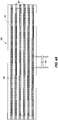
- FIG 5 is a perspective view of another example of a heater assembly 200 which may be utilized in some embodiments of this invention.
- a heating element 200 may include heater coils or elements 202 embedded within a heating element body 201, with vertical columns 201a protruding outwardly from the heating element body. Between the respective columns 201a are vertical channels or grooves 205 which expose the heater coils or elements 202 and provide an area for the addition of other desirable materials, such as a high temperature thermal inducing cement (shown and discussed in later Figures).
- Figure 6 is a perspective view of an example of a heater assembly 210 which may be utilized in some embodiments of this invention.
- Figure 6 illustrates a heater body 211, the high temperature thermal inducing cement 213 filling what were recesses or grooves in the heater assembly body 211.
- the heater body 211 has interior facing surfaces 211a which would combine with the thermal inducing cement 213 to form an interface surface 214 that would then typically be abutted against a refractory body or a containment shell if a layer of thermal inducing cement is not placed between that interface surface 214 and either the refractory body or the containment shell.
- the columns 211a are the same or similar material as the rest of the heater body 211, whereas the material within the grooves or slots is of a different material, such as a high temperature thermal inducing grout-like material or cement 213.
- Figure 6 therefore results in a surface or interface of the heating element which may include alternate columns of dissimilar material through which the heat is transmitted.
- the high temperature heat inducing cement 213 would have one thermal conductivity and set of properties
- the heating element body columns 211a would have a set of properties dissimilar to that of the high temperature heat inducing cement 213. This has the effect of creating an alternating or distributed heat transfer distribution (by conduction) different than if the front surface of the heating element 210 were a continuous flat surface of the same material.
- Figure 7 is a perspective view of an example of a heating element 220 which may be utilized in some embodiments of this invention.
- Figure 7 illustrates heating element body 221 with vertical grooves 221a and inward facing surfaces 221b of the heater assembly body, high temperature heat inducing cement 223 filling the grooves 221a and an additional layer of the high temperature heat inducing cement 222 covering the inward facing surfaces 221b and the inward facing surface of the high temperature thermal inducing cement 223.
- Figure 8 is a perspective view of an alternate configuration of the example of the heater assembly 220 illustrated in Figure 7 , and which may be utilized in some embodiments of this invention.
- Figure 8 illustrates heating element body 221 without any vertical grooves or columns therein, but with an additional layer of the high temperature heat inducing cement 222 covering the surface or interface of the heating elements.
- Figure 9 is a cross-section view of another example of an embodiment of this invention 130, showing refractory trough body 132 with trough bottom 132a, first side wall 132b and second side wall 132c of trough body 132.
- Figure 8 shows heating elements or heater assemblies 140 with heating coils 141 contained within heating element bodies 144.
- Figure 9 illustrates an embodiment of the invention similar to Figure 2 , only wherein a layer of the high temperature inducing cement 149 is provided between a relatively flat or smooth surface of the heater assembly 140 and the castable refractory body 132. Like numbered items are the same as in Figure 2 and will not be repeated here. Figure 9 therefore illustrates a configuration of one embodiment of this invention wherein the interface surface 148 of the heater assembly abuts a layer of high temperature (and high thermal conductivity) thermal inducing layer 149 (which may be a high temperature thermal inducing cement as described elsewhere herein or it may be some other abutting thermal inducing layer).
- Figure 9 illustrates heater assemblies 140 without grooves (as shown for example in Figure 4B ) but instead with a continuous layer of the high temperature thermal inducing cement 149 at, near or adjacent to the heater elements 141. In this case the later of the high temperature thermal inducing cement 149 allows heater coils 141 to be placed at or near the inner facing surface 148 of the heater assemblies 140.
- the heater coils are set back or spaced apart from the surface of the heater assembly that for instance abuts or interfaces with the containment shell or fence, or that abuts or interfaces with the refractory body.
- the columns on the heater panel assembly that would typically interface would generally have a lower thermal conductivity.
- the high temperature thermal inducing cement that may be added in embodiments of this invention may have a higher thermal conductivity, which improves the efficiency of the heating system in embodiments of this invention. This type of configuration would have improved system energy performance while maintaining the spacing of the heater coils within the heater assembly and the interface.
- the layer of high temperature thermal inducing cement transmits the heat more efficiently without creating undesired hot spots and other undesirable results.
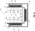
- Figure 10 is a cross-section view of the example of another aspect of the embodiment of this invention shown in Figure 2 , only further including a heater 151 positioned below or as part of the bottom wall (or floor) of the trough.
- a heater is utilized below the trough, instead of the layer between the heater and the trough being an insulator (similar to item 134 in Figure 2 , it would instead be a thermally conductive layer 152.
- a conductive layer 152 may or may not be utilized depending on the specific application.
- Figure 11 is a cross-section view of an additional aspect of the example of the embodiment of the invention shown in Figure 9 , only further including a force imparted inwardly on the shell to maintain or improve on the contact and conduction of heat from the heaters through the refractory first side wall 132b and second side wall 132c.
- a force imparted inwardly on the shell to maintain or improve on the contact and conduction of heat from the heaters through the refractory first side wall 132b and second side wall 132c.
- any one of a number of known presses or force-inducing devices 153, 153a may be utilized to impart the inward force on the opposing walls of the trough shell, with no one in particular being required to practice the invention.
- the press may be used from the beginning of the service of the part or it may be implemented in stages throughout the service life to attempt to maintain maximum material continuity to maximize thermal conduction.
- Like numbered items from Figure 9 are also shown and will not be repeated or described again herein.
- a molten metal handling device comprising: an outer casing with a bottom and two side walls generally defining an inner cavity; one or more heater assemblies within the outer casing, each heater assembly comprising: a heater assembly body with an inward facing surface, the inward facing surface including recesses; heater coils within the heater assembly body spaced apart from the inward facing surface of the heater assembly body; a castable refractory body defining a molten metal carrying cavity with a bottom wall, a first side wall and a second side wall, the castable refractory body abutting the one or more heater assemblies; and wherein thermal inducing cement is disposed within the recesses in the inward facing surface of the heater assembly body, facilitating conductive heat transfer from the heater coils through the thermal inducing cement to the refractory body.
- thermal inducing cement has a thermal conductivity different than inward facing surface the one or more heater assembly bodies; further comprising a containment shell between and abutting the one or more heater assemblies and the refractory body; further wherein the containment shell is made of reinforced fiberglass material; further wherein the inward facing surface of the heater assembly body and the thermal inducing cement disposed within the recesses in the inward facing surface of the heater assembly body, combine to facilitate conductive heat transfer from the heater coils to the refractory body; further wherein the thermal expansion properties of the containment shell are correlated to the thermal expansion properties of the inward facing surface of the heater assembly body and the thermal inducing cement disposed within the recesses in the inward facing surface of the heater assembly body, to reduce separation during thermal expansion and contraction; further wherein the thermal expansion properties of the containment shell are correlated to the thermal expansion properties of the inward facing surface of the heater assembly body and the thermal in
- a molten metal handling device further wherein the combination of the inward facing surface of the heater assembly and the thermal inducing cement disposed within the recesses in the inward facing surface of the heater assembly combine to form a conductive interface surface, with possible further aspects comprised of a layer of thermal inducing cement between the conductive interface surface and the refractory body and in embodiments in which a containment shell is between the refractory body and the heater assemblies, a layer of thermal inducing cement between the containment shell and one or both of the conductive interface surface and/or the refractory body.
- the thermal expansion properties of the containment shell may be correlated to the thermal expansion properties of the layer of thermal inducing cement between the conductive interface surface, the thermal expansion properties of the heater assembly interface and/or the refractory body, within the contemplation of this invention.
- a molten metal handling device which comprises: an outer casing with a bottom and two side walls generally defining an inner cavity; one or more heater assemblies within the outer casing, each heater assembly including a continuous inward facing surface and heater coils within the heater assembly body and adjacent the inward facing surface; a containment shell with a bottom and two side walls, the containment shell being within and abutting the inward facing surfaces of the one or more heating assemblies; a layer of thermal inducing cement sandwiched between the containment shell and the inward facing surfaces of the one or more heater assemblies; and a castable refractory body defining a molten metal carrying cavity with a bottom wall, a first side wall and a second side wall, the castable refractory body being within and abutting the containment shell.
- a molten metal handling device which comprises: an outer casing defined by a bottom and two side walls generally defining an inner cavity; a castable refractory body defining a molten metal carrying cavity with a bottom wall, a first side wall and a second side wall; one or more heater assemblies, each heater assembly comprising: a heater assembly body with an interface surface abutting the two side walls of the containment shell, the heater assembly body having a heater assembly thermal expansion coefficient; a containment shell between the refractory body and the one or more heater assemblies, the containment fence having a containment shell thermal expansion coefficient; wherein the heater assembly thermal expansion coefficient is correlated to the containment shell thermal expansion coefficient such that the two are compatible, thereby reducing separation during thermal expansion and contraction.
Landscapes
- Engineering & Computer Science (AREA)
- Mechanical Engineering (AREA)
- General Engineering & Computer Science (AREA)
- Chemical & Material Sciences (AREA)
- Physics & Mathematics (AREA)
- Electromagnetism (AREA)
- Metallurgy (AREA)
- Organic Chemistry (AREA)
- Materials Engineering (AREA)
- Manufacturing & Machinery (AREA)
- Thermal Sciences (AREA)
- Crystallography & Structural Chemistry (AREA)
- Furnace Details (AREA)
- General Induction Heating (AREA)
- Casting Support Devices, Ladles, And Melt Control Thereby (AREA)
Claims (15)
- Vorrichtung zur Handhabung von geschmolzenem Metall, die Folgendes umfasst:ein äußeres Gehäuse (116) mit einem Boden und zwei Seitenwänden, die im Allgemeinen einen inneren Hohlraum definieren,eine oder mehrere Heizbaugruppen (107, 180, 200, 210, 220) innerhalb des äußeren Gehäuses (116), wobei jede Heizbaugruppe (107, 180, 200, 210, 220) Folgendes umfasst:einen Heizbaugruppenkörper (112, 181, 201, 211, 221) mit einer nach innen zeigenden Fläche (112a), wobei die nach innen zeigende Fläche (112a) Aussparungen einschließt,Heizspulen (108, 183, 202) innerhalb des Heizbaugruppenkörpers (112), die von der nach innen zeigenden Fläche (112a) des Heizbaugruppenkörpers (112) beabstandet sind,einen Feuerfestbetonkörper (103), der an die eine oder die mehreren Heizbaugruppen (107) angrenzt, wobei der Feuerfestbetonkörper (103) einen Beförderungsholraum für geschmolzenes Metall mit einer Bodenwand (103a), einer ersten Seitenwand (103b) und einer zweiten Seitenwand (103c) definiert, undwobei ein Wärmeinduktionszement (110) innerhalb der Aussparungen in der nach innen zeigenden Fläche (112a) des Heizbaugruppenkörpers (112) angeordnet ist, was leitende Wärmeübertragung von den Heizspulen (108, 183, 202) durch den Wärmeinduktionszement (110, 213, 223) zu dem feuerfesten Körper (103) erleichtert.
- Vorrichtung zur Handhabung von geschmolzenem Metall nach Anspruch 1 und ferner, wobei der Wärmeinduktionszement (110, 213, 223) eine andere Wärmeleitfähigkeit aufweist als die nach innen zeigende Fläche (112a) des einen oder der mehreren Heizbaugruppenkörper (112, 181, 201, 211, 221).
- Vorrichtung zur Handhabung von geschmolzenem Metall nach Anspruch 1 oder Anspruch 2 und, die ferner eine Einschließungshülle (106) zwischen der einen oder den mehreren Heizbaugruppen (107, 180, 200, 210, 220) und dem feuerfesten Körper (103) und an dieselben anstoßend umfasst.
- Vorrichtung zur Handhabung von geschmolzenem Metall nach Anspruch 3 und ferner, wobei die Einschließungshülle (106) aus verstärktem Fiberglasmaterial hergestellt ist.
- Vorrichtung zur Handhabung von geschmolzenem Metall nach Anspruch 1 und ferner, wobei sich die Kombination der nach innen zeigenden Fläche (112a) der Heizbaugruppe (107, 180, 200, 210, 220) und des Wärmeinduktionszements (110, 213, 223), der innerhalb der Aussparungen in der nach innen zeigenden Fläche (112a) der Heizbaugruppe (107, 180, 200, 210, 220) angeordnet ist, kombinieren, um eine leitende Grenzfläche zu bilden.
- Vorrichtung zur Handhabung von geschmolzenem Metall nach Anspruch 5 und, die ferner eine zusätzliche Lage von Wärmeinduktionszement (222) zwischen der leitenden Grenzfläche und dem feuerfesten Körper (103) umfasst.
- Vorrichtung zur Handhabung von geschmolzenem Metall nach Anspruch 6 und, die ferner eine Einschließungshülle (106) zwischen der Lage von Wärmeinduktionszement (222) und dem feuerfesten Körper (103) umfasst.
- Vorrichtung zur Handhabung von geschmolzenem Metall nach Anspruch 7 und ferner, wobei die Einschließungshülle (106) aus verstärktem Fiberglasmaterial hergestellt ist.
- Vorrichtung zur Handhabung von geschmolzenem Metall nach Anspruch 3 und ferner, wobei die Wärmeausdehnungseigenschaften der Einschließungshülle (106) mit den Wärmeausdehnungseigenschaften der nach innen zeigenden Fläche (112a) des Heizbaugruppenkörpers (112, 181, 201, 211, 221) und des Wärmeinduktionszements (110, 213, 223), der innerhalb der Aussparungen in der nach innen zeigenden Fläche (112a) des Heizbaugruppenkörpers (112, 181, 201, 211, 221) angeordnet ist, in Wechselbeziehung stehen, um die Trennung während Wärmeausdehnung und -kontraktion zu verringern.
- Vorrichtung zur Handhabung von geschmolzenem Metall nach Anspruch 6 und ferner, wobei die Wärmeausdehnungseigenschaften der Einschließungshülle (106) mit den Wärmeausdehnungseigenschaften der Lage von Wärmeinduktionszement (222) zwischen der leitenden Grenzfläche und dem feuerfesten Körper (103) in Wechselbeziehung stehen.
- Vorrichtung zur Handhabung von geschmolzenem Metall nach Anspruch 1 und ferner, wobei sich die nach innen zeigende Fläche (112a) des Heizbaugruppenkörpers (112, 181, 201, 211, 221) und der Wärmeinduktionszement (110, 213, 223), der innerhalb der Aussparungen in der nach innen zeigenden Fläche (112a) des Heizbaugruppenkörpers (112, 181, 201, 211, 221) angeordnet ist, kombinieren, um eine leitende Wärmeübertragung von den Heizspulen (108, 183, 202) zu dem feuerfesten Körper (103) zu erleichtern.
- Vorrichtung zur Handhabung von geschmolzenem Metall nach Anspruch 7 und ferner, wobei sich die Kombination der nach innen zeigenden Fläche (112a) des Heizbaugruppenkörpers (112, 181, 201, 211, 221) und des Wärmeinduktionszements (110, 213, 223), der innerhalb der Aussparungen in der nach innen zeigenden Fläche (112a) des Heizbaugruppenkörpers (112, 181, 201, 211, 221) angeordnet ist, zusammen mit der Lage von Wärmeinduktionszement (222) zwischen der leitenden Grenzfläche und dem feuerfesten Körper (103) und der Einschließungshülle (106) kombinieren, um eine leitende Wärmeübertragung von den Heizspulen (108, 183, 202) zu dem feuerfesten Körper (103) zu erleichtern.
- Vorrichtung zur Handhabung von geschmolzenem Metall nach Anspruch 1 und, die ferner eine Press (153) umfasst, die dafür angeordnet ist, eine Kraft nach innen auf die zwei Seitenwände des äußeren Gehäuses (116) auszuüben, die ausreicht, um die nach innen zeigende Fläche (112a) des Heizbaugruppenkörpers (112, 181, 201, 211, 221) hin zu dem feuerfesten Körper (103) zusammenzudrücken.
- Vorrichtung (130) zur Handhabung von geschmolzenem Metall, die Folgendes umfasst:ein äußeres Gehäuse (146) mit einem Boden und zwei Seitenwänden, die im Allgemeinen einen inneren Hohlraum definieren,eine oder mehrere Heizbaugruppen (140) innerhalb des äußeren Gehäuses (146), wobei jede Heizbaugruppe eine durchgehende nach innen zeigende Fläche (144a) einschließt, undHeizspulen (141) innerhalb der Heizbaugruppe (140) und angrenzend an die nach innen zeigende Fläche (144a),eine Einschließungshülle (135) mit einem Boden und zwei Seitenwänden, wobei die Einschließungshülle (135) sich innerhalb der nach innen zeigenden Flächen (144a) der einen oder der mehreren Heizbaugruppen (140) befindet und an dieselben angrenzt,einen Feuerfestbetonkörper (123), der einen Beförderungsholraum für geschmolzenes Metall mit einer Bodenwand (132a), einer ersten Seitenwand (132b) und einer zweiten Seitenwand (132c) definiert, wobei der Feuerfestbetonkörper (132) sich innerhalb der Einschließungshülle (135) befindet und an dieselbe angrenzt, undeine Lage von Wärmeinduktionszement (222), die zwischen der Einschließungshülle (135) und den nach innen zeigenden Flächen (144a) der einen oder der mehreren Heizbaugruppen (140) eingeschoben ist, was eine leitende Wärmeübertragung von den Heizspulen durch den Wärmeinduktionszement zu dem feuerfesten Körper erleichtert.
- Vorrichtung (130) zur Handhabung von geschmolzenem Metall nach Anspruch 14 und ferner, wobei die Wärmeausdehnungseigenschaften der Einschließungshülle (135) mit den Wärmeausdehnungseigenschaften der Lage von Wärmeinduktionszement (222) zwischen der leitenden Grenzfläche und dem feuerfesten Körper (132) in Wechselbeziehung stehen, um die Trennung während Wärmeausdehnung und -kontraktion zu verringern.
Priority Applications (1)
| Application Number | Priority Date | Filing Date | Title |
|---|---|---|---|
| PL16812124T PL3307461T3 (pl) | 2015-06-15 | 2016-05-24 | System ogrzewania urządzenia do przenoszenia stopionego metalu |
Applications Claiming Priority (2)
| Application Number | Priority Date | Filing Date | Title |
|---|---|---|---|
| US14/739,783 US9781776B2 (en) | 2015-06-15 | 2015-06-15 | Molten metal handling device heating system |
| PCT/US2016/033956 WO2016204948A1 (en) | 2015-06-15 | 2016-05-24 | Molten metal handling device heating system |
Publications (4)
| Publication Number | Publication Date |
|---|---|
| EP3307461A1 EP3307461A1 (de) | 2018-04-18 |
| EP3307461A4 EP3307461A4 (de) | 2019-02-27 |
| EP3307461B1 true EP3307461B1 (de) | 2021-03-10 |
| EP3307461B8 EP3307461B8 (de) | 2021-05-19 |
Family
ID=57516315
Family Applications (1)
| Application Number | Title | Priority Date | Filing Date |
|---|---|---|---|
| EP16812124.2A Active EP3307461B8 (de) | 2015-06-15 | 2016-05-24 | Heizsystem für vorrichtung zur handhabung von metallschmelze |
Country Status (8)
| Country | Link |
|---|---|
| US (1) | US9781776B2 (de) |
| EP (1) | EP3307461B8 (de) |
| CN (1) | CN107848028B (de) |
| CA (1) | CA2986958C (de) |
| ES (1) | ES2868598T3 (de) |
| HU (1) | HUE054953T2 (de) |
| PL (1) | PL3307461T3 (de) |
| WO (1) | WO2016204948A1 (de) |
Families Citing this family (5)
| Publication number | Priority date | Publication date | Assignee | Title |
|---|---|---|---|---|
| CN106825457A (zh) * | 2017-03-14 | 2017-06-13 | 派罗特克(广西南宁)高温材料有限公司 | 一种预埋式电加热流槽 |
| CN109879231A (zh) * | 2019-01-14 | 2019-06-14 | 湖南鸿飞机械有限公司 | 一种液态金属远距离输送方法及其装置 |
| CN112944919A (zh) * | 2019-11-26 | 2021-06-11 | 科德尔科股份公司 | 用于转移熔炼炉中白金属的热通道 |
| US20220111434A1 (en) | 2020-10-08 | 2022-04-14 | Wagstaff, Inc. | Material, apparatus, and method for refractory castings |
| US20240357712A1 (en) | 2023-04-21 | 2024-10-24 | Wagstaff, Inc. | Material, apparatus, and method for electrically shielding heated components |
Family Cites Families (15)
| Publication number | Priority date | Publication date | Assignee | Title |
|---|---|---|---|---|
| US3235243A (en) * | 1963-09-12 | 1966-02-15 | Pennsalt Chemicals Corp | Apparatus for producing ultraclean alloy steels |
| US3677682A (en) * | 1970-03-09 | 1972-07-18 | Ladislao Wladyslaw Putkowski | Hot runner system |
| US3751571A (en) | 1972-03-29 | 1973-08-07 | Norton Co | Refractory cement lining for coreless induction furnaces |
| JPS52145341A (en) * | 1976-05-31 | 1977-12-03 | Shin Kobe Electric Machinery | Heating method of molten lead pipe line |
| US4345743A (en) | 1980-10-10 | 1982-08-24 | Alcan Research And Development Limited | Means and method for containing flowing or standing molten metal |
| JPH0737880B2 (ja) * | 1989-06-28 | 1995-04-26 | 新日本製鐵株式会社 | 誘導溶解炉 |
| DE3934393A1 (de) * | 1989-10-14 | 1991-04-18 | Krauss Marmorheizung Gmbh | Verkleidungs-platte aus stein mit heizleiter |
| US5850073A (en) * | 1997-02-18 | 1998-12-15 | Eckert; C. Edward | Electric heating element and heater assembly |
| US6470041B2 (en) * | 1999-01-12 | 2002-10-22 | C. Edward Eckert | Heater assembly and heated trough for molten aluminum |
| US6444165B1 (en) | 1999-01-12 | 2002-09-03 | C. Edward Eckert | Heated trough for molten aluminum |
| US6973955B2 (en) * | 2003-12-11 | 2005-12-13 | Novelis Inc. | Heated trough for molten metal |
| GB2458964A (en) * | 2008-04-04 | 2009-10-07 | Elmelin Plc | Induction furnace lining |
| DE102008036790B4 (de) * | 2008-08-07 | 2014-05-15 | Tmt Tapping-Measuring-Technology Gmbh | Abstichkanal zur Ableitung von Eisen- und Metallschmelzen sowie flüssige Schlacke aus metallurgischen Behältern, wie Hochöfen und Schmelzöfen |
| US9095896B2 (en) | 2008-11-03 | 2015-08-04 | Pyrotek, Inc. | Heated molten metal handling device |
| GB2522349B (en) | 2011-06-21 | 2015-12-09 | Pyrotek Engineering Materials | Metal transfer device |
-
2015
- 2015-06-15 US US14/739,783 patent/US9781776B2/en active Active
-
2016
- 2016-05-24 EP EP16812124.2A patent/EP3307461B8/de active Active
- 2016-05-24 WO PCT/US2016/033956 patent/WO2016204948A1/en not_active Ceased
- 2016-05-24 CN CN201680034876.5A patent/CN107848028B/zh not_active Expired - Fee Related
- 2016-05-24 CA CA2986958A patent/CA2986958C/en active Active
- 2016-05-24 PL PL16812124T patent/PL3307461T3/pl unknown
- 2016-05-24 HU HUE16812124A patent/HUE054953T2/hu unknown
- 2016-05-24 ES ES16812124T patent/ES2868598T3/es active Active
Non-Patent Citations (1)
| Title |
|---|
| None * |
Also Published As
| Publication number | Publication date |
|---|---|
| HUE054953T2 (hu) | 2021-10-28 |
| CA2986958C (en) | 2023-09-26 |
| WO2016204948A1 (en) | 2016-12-22 |
| EP3307461A1 (de) | 2018-04-18 |
| CN107848028B (zh) | 2020-10-02 |
| US9781776B2 (en) | 2017-10-03 |
| EP3307461B8 (de) | 2021-05-19 |
| PL3307461T3 (pl) | 2021-07-05 |
| CA2986958A1 (en) | 2016-12-22 |
| US20160366727A1 (en) | 2016-12-15 |
| EP3307461A4 (de) | 2019-02-27 |
| CN107848028A (zh) | 2018-03-27 |
| ES2868598T3 (es) | 2021-10-21 |
Similar Documents
| Publication | Publication Date | Title |
|---|---|---|
| EP3307461B1 (de) | Heizsystem für vorrichtung zur handhabung von metallschmelze | |
| CA2419486A1 (en) | Radiant heating system pipe mounting plate | |
| NZ202455A (en) | Storage heater:air circulation between and around a stack of loosely interlocked bricks having projections and recesses on opposed faces | |
| US3987237A (en) | Electric furnace wall construction | |
| GB2040418A (en) | Kiln furniture setting | |
| CN110036120A (zh) | 块体结构、容器和构造块体结构的方法 | |
| AU2016282636A1 (en) | Method for sintering carbon bodies in a furnace device | |
| JP6508903B2 (ja) | ユニット、連続式加熱炉および連続式加熱炉の製造方法 | |
| RU2516253C2 (ru) | Монолитный тепловой нагревательный блок из огнеупорного фосфатного бетона | |
| EP3784843B1 (de) | Gebäudekonstruktion mit sandwichplattenwand und verfahren zum feuerschutz einer solchen gebäudekonstruktion | |
| US11287188B2 (en) | Refractory furnace structure | |
| CN207609051U (zh) | 墙体结构及房屋结构 | |
| CN205448692U (zh) | 一种新型耐火砖 | |
| JP2016148466A (ja) | 複合断熱材及びその製造方法 | |
| CN105276990A (zh) | 一种新型耐火砖 | |
| EP0911594B1 (de) | Auskleidungsblöcke und daraus aufgebaute Ofenauskleidung | |
| CN105971215A (zh) | 一种新型金属装饰保温板防变形加强结构 | |
| CN109595943A (zh) | 一种轻质耐火砖 | |
| RU2056026C1 (ru) | Тепловая изоляция вертикальных подовых труб | |
| JPS6125596Y2 (de) | ||
| US1646058A (en) | Electric furnace | |
| GB1567715A (en) | Electric slot furnace | |
| SU1543212A1 (ru) | Футеровка печи | |
| CN201680423U (zh) | 一种石窑煨炉 | |
| CN206942013U (zh) | 复合铝单板 |
Legal Events
| Date | Code | Title | Description |
|---|---|---|---|
| STAA | Information on the status of an ep patent application or granted ep patent |
Free format text: STATUS: THE INTERNATIONAL PUBLICATION HAS BEEN MADE |
|
| PUAI | Public reference made under article 153(3) epc to a published international application that has entered the european phase |
Free format text: ORIGINAL CODE: 0009012 |
|
| STAA | Information on the status of an ep patent application or granted ep patent |
Free format text: STATUS: REQUEST FOR EXAMINATION WAS MADE |
|
| 17P | Request for examination filed |
Effective date: 20171128 |
|
| AK | Designated contracting states |
Kind code of ref document: A1 Designated state(s): AL AT BE BG CH CY CZ DE DK EE ES FI FR GB GR HR HU IE IS IT LI LT LU LV MC MK MT NL NO PL PT RO RS SE SI SK SM TR |
|
| AX | Request for extension of the european patent |
Extension state: BA ME |
|
| DAV | Request for validation of the european patent (deleted) | ||
| DAX | Request for extension of the european patent (deleted) | ||
| A4 | Supplementary search report drawn up and despatched |
Effective date: 20190129 |
|
| RIC1 | Information provided on ipc code assigned before grant |
Ipc: F27D 3/14 20060101ALI20190123BHEP Ipc: H05B 6/36 20060101ALI20190123BHEP Ipc: B22D 41/02 20060101ALI20190123BHEP Ipc: B22D 41/01 20060101ALI20190123BHEP Ipc: F27D 1/00 20060101ALI20190123BHEP Ipc: F27D 11/02 20060101ALI20190123BHEP Ipc: C21B 7/14 20060101ALI20190123BHEP Ipc: F27D 99/00 20100101ALI20190123BHEP Ipc: H05B 6/18 20060101AFI20190123BHEP Ipc: B22D 35/04 20060101ALI20190123BHEP |
|
| REG | Reference to a national code |
Ref country code: DE Ref legal event code: R079 Ref document number: 602016054115 Country of ref document: DE Free format text: PREVIOUS MAIN CLASS: B22D0035040000 Ipc: H05B0006180000 |
|
| GRAP | Despatch of communication of intention to grant a patent |
Free format text: ORIGINAL CODE: EPIDOSNIGR1 |
|
| STAA | Information on the status of an ep patent application or granted ep patent |
Free format text: STATUS: GRANT OF PATENT IS INTENDED |
|
| RIC1 | Information provided on ipc code assigned before grant |
Ipc: F27D 1/00 20060101ALI20201112BHEP Ipc: H05B 6/36 20060101ALI20201112BHEP Ipc: F27D 3/14 20060101ALI20201112BHEP Ipc: F27D 11/02 20060101ALI20201112BHEP Ipc: B22D 41/02 20060101ALI20201112BHEP Ipc: H05B 6/18 20060101AFI20201112BHEP Ipc: C21B 7/14 20060101ALI20201112BHEP Ipc: F27D 99/00 20100101ALI20201112BHEP Ipc: B22D 35/04 20060101ALI20201112BHEP Ipc: B22D 41/01 20060101ALI20201112BHEP |
|
| INTG | Intention to grant announced |
Effective date: 20201127 |
|
| GRAS | Grant fee paid |
Free format text: ORIGINAL CODE: EPIDOSNIGR3 |
|
| GRAA | (expected) grant |
Free format text: ORIGINAL CODE: 0009210 |
|
| STAA | Information on the status of an ep patent application or granted ep patent |
Free format text: STATUS: THE PATENT HAS BEEN GRANTED |
|
| AK | Designated contracting states |
Kind code of ref document: B1 Designated state(s): AL AT BE BG CH CY CZ DE DK EE ES FI FR GB GR HR HU IE IS IT LI LT LU LV MC MK MT NL NO PL PT RO RS SE SI SK SM TR |
|
| REG | Reference to a national code |
Ref country code: GB Ref legal event code: FG4D |
|
| REG | Reference to a national code |
Ref country code: AT Ref legal event code: REF Ref document number: 1371290 Country of ref document: AT Kind code of ref document: T Effective date: 20210315 Ref country code: CH Ref legal event code: EP |
|
| REG | Reference to a national code |
Ref country code: DE Ref legal event code: R096 Ref document number: 602016054115 Country of ref document: DE |
|
| REG | Reference to a national code |
Ref country code: IE Ref legal event code: FG4D |
|
| REG | Reference to a national code |
Ref country code: CH Ref legal event code: NV Representative=s name: SERVOPATENT GMBH, CH |
|
| REG | Reference to a national code |
Ref country code: CH Ref legal event code: PK Free format text: BERICHTIGUNG B8 |
|
| REG | Reference to a national code |
Ref country code: RO Ref legal event code: EPE |
|
| REG | Reference to a national code |
Ref country code: SK Ref legal event code: T3 Ref document number: E 36902 Country of ref document: SK |
|
| REG | Reference to a national code |
Ref country code: CH Ref legal event code: PK Free format text: BERICHTIGUNG INHABER |
|
| REG | Reference to a national code |
Ref country code: NL Ref legal event code: FP |
|
| REG | Reference to a national code |
Ref country code: GR Ref legal event code: EP Ref document number: 20210401373 Country of ref document: GR Effective date: 20210614 |
|
| REG | Reference to a national code |
Ref country code: SE Ref legal event code: TRGR |
|
| REG | Reference to a national code |
Ref country code: LT Ref legal event code: MG9D |
|
| PG25 | Lapsed in a contracting state [announced via postgrant information from national office to epo] |
Ref country code: HR Free format text: LAPSE BECAUSE OF FAILURE TO SUBMIT A TRANSLATION OF THE DESCRIPTION OR TO PAY THE FEE WITHIN THE PRESCRIBED TIME-LIMIT Effective date: 20210310 Ref country code: FI Free format text: LAPSE BECAUSE OF FAILURE TO SUBMIT A TRANSLATION OF THE DESCRIPTION OR TO PAY THE FEE WITHIN THE PRESCRIBED TIME-LIMIT Effective date: 20210310 Ref country code: LT Free format text: LAPSE BECAUSE OF FAILURE TO SUBMIT A TRANSLATION OF THE DESCRIPTION OR TO PAY THE FEE WITHIN THE PRESCRIBED TIME-LIMIT Effective date: 20210310 Ref country code: BG Free format text: LAPSE BECAUSE OF FAILURE TO SUBMIT A TRANSLATION OF THE DESCRIPTION OR TO PAY THE FEE WITHIN THE PRESCRIBED TIME-LIMIT Effective date: 20210610 |
|
| REG | Reference to a national code |
Ref country code: NO Ref legal event code: T2 Effective date: 20210310 |
|
| PG25 | Lapsed in a contracting state [announced via postgrant information from national office to epo] |
Ref country code: RS Free format text: LAPSE BECAUSE OF FAILURE TO SUBMIT A TRANSLATION OF THE DESCRIPTION OR TO PAY THE FEE WITHIN THE PRESCRIBED TIME-LIMIT Effective date: 20210310 Ref country code: LV Free format text: LAPSE BECAUSE OF FAILURE TO SUBMIT A TRANSLATION OF THE DESCRIPTION OR TO PAY THE FEE WITHIN THE PRESCRIBED TIME-LIMIT Effective date: 20210310 |
|
| REG | Reference to a national code |
Ref country code: ES Ref legal event code: FG2A Ref document number: 2868598 Country of ref document: ES Kind code of ref document: T3 Effective date: 20211021 |
|
| REG | Reference to a national code |
Ref country code: HU Ref legal event code: AG4A Ref document number: E054953 Country of ref document: HU |
|
| PG25 | Lapsed in a contracting state [announced via postgrant information from national office to epo] |
Ref country code: SM Free format text: LAPSE BECAUSE OF FAILURE TO SUBMIT A TRANSLATION OF THE DESCRIPTION OR TO PAY THE FEE WITHIN THE PRESCRIBED TIME-LIMIT Effective date: 20210310 Ref country code: EE Free format text: LAPSE BECAUSE OF FAILURE TO SUBMIT A TRANSLATION OF THE DESCRIPTION OR TO PAY THE FEE WITHIN THE PRESCRIBED TIME-LIMIT Effective date: 20210310 |
|
| PG25 | Lapsed in a contracting state [announced via postgrant information from national office to epo] |
Ref country code: PT Free format text: LAPSE BECAUSE OF FAILURE TO SUBMIT A TRANSLATION OF THE DESCRIPTION OR TO PAY THE FEE WITHIN THE PRESCRIBED TIME-LIMIT Effective date: 20210712 |
|
| REG | Reference to a national code |
Ref country code: DE Ref legal event code: R097 Ref document number: 602016054115 Country of ref document: DE |
|
| PLBE | No opposition filed within time limit |
Free format text: ORIGINAL CODE: 0009261 |
|
| STAA | Information on the status of an ep patent application or granted ep patent |
Free format text: STATUS: NO OPPOSITION FILED WITHIN TIME LIMIT |
|
| PG25 | Lapsed in a contracting state [announced via postgrant information from national office to epo] |
Ref country code: DK Free format text: LAPSE BECAUSE OF FAILURE TO SUBMIT A TRANSLATION OF THE DESCRIPTION OR TO PAY THE FEE WITHIN THE PRESCRIBED TIME-LIMIT Effective date: 20210310 Ref country code: AL Free format text: LAPSE BECAUSE OF FAILURE TO SUBMIT A TRANSLATION OF THE DESCRIPTION OR TO PAY THE FEE WITHIN THE PRESCRIBED TIME-LIMIT Effective date: 20210310 Ref country code: LU Free format text: LAPSE BECAUSE OF NON-PAYMENT OF DUE FEES Effective date: 20210524 Ref country code: MC Free format text: LAPSE BECAUSE OF FAILURE TO SUBMIT A TRANSLATION OF THE DESCRIPTION OR TO PAY THE FEE WITHIN THE PRESCRIBED TIME-LIMIT Effective date: 20210310 |
|
| REG | Reference to a national code |
Ref country code: BE Ref legal event code: MM Effective date: 20210531 |
|
| 26N | No opposition filed |
Effective date: 20211213 |
|
| PG25 | Lapsed in a contracting state [announced via postgrant information from national office to epo] |
Ref country code: SI Free format text: LAPSE BECAUSE OF FAILURE TO SUBMIT A TRANSLATION OF THE DESCRIPTION OR TO PAY THE FEE WITHIN THE PRESCRIBED TIME-LIMIT Effective date: 20210310 |
|
| PG25 | Lapsed in a contracting state [announced via postgrant information from national office to epo] |
Ref country code: IE Free format text: LAPSE BECAUSE OF NON-PAYMENT OF DUE FEES Effective date: 20210524 |
|
| PGFP | Annual fee paid to national office [announced via postgrant information from national office to epo] |
Ref country code: SE Payment date: 20220310 Year of fee payment: 7 |
|
| PGFP | Annual fee paid to national office [announced via postgrant information from national office to epo] |
Ref country code: NL Payment date: 20220420 Year of fee payment: 7 |
|
| PG25 | Lapsed in a contracting state [announced via postgrant information from national office to epo] |
Ref country code: BE Free format text: LAPSE BECAUSE OF NON-PAYMENT OF DUE FEES Effective date: 20210531 |
|
| PGFP | Annual fee paid to national office [announced via postgrant information from national office to epo] |
Ref country code: SK Payment date: 20220413 Year of fee payment: 7 Ref country code: RO Payment date: 20220427 Year of fee payment: 7 Ref country code: IT Payment date: 20220412 Year of fee payment: 7 Ref country code: HU Payment date: 20220412 Year of fee payment: 7 Ref country code: ES Payment date: 20220606 Year of fee payment: 7 |
|
| PGFP | Annual fee paid to national office [announced via postgrant information from national office to epo] |
Ref country code: TR Payment date: 20220524 Year of fee payment: 7 Ref country code: GR Payment date: 20220420 Year of fee payment: 7 Ref country code: AT Payment date: 20220425 Year of fee payment: 7 |
|
| PGFP | Annual fee paid to national office [announced via postgrant information from national office to epo] |
Ref country code: IS Payment date: 20220405 Year of fee payment: 7 |
|
| PG25 | Lapsed in a contracting state [announced via postgrant information from national office to epo] |
Ref country code: CY Free format text: LAPSE BECAUSE OF FAILURE TO SUBMIT A TRANSLATION OF THE DESCRIPTION OR TO PAY THE FEE WITHIN THE PRESCRIBED TIME-LIMIT Effective date: 20210310 |
|
| REG | Reference to a national code |
Ref country code: SE Ref legal event code: EUG |
|
| REG | Reference to a national code |
Ref country code: NL Ref legal event code: MM Effective date: 20230601 |
|
| REG | Reference to a national code |
Ref country code: SK Ref legal event code: MM4A Ref document number: E 36902 Country of ref document: SK Effective date: 20230524 |
|
| REG | Reference to a national code |
Ref country code: AT Ref legal event code: MM01 Ref document number: 1371290 Country of ref document: AT Kind code of ref document: T Effective date: 20230524 |
|
| PG25 | Lapsed in a contracting state [announced via postgrant information from national office to epo] |
Ref country code: SK Free format text: LAPSE BECAUSE OF NON-PAYMENT OF DUE FEES Effective date: 20230524 |
|
| PG25 | Lapsed in a contracting state [announced via postgrant information from national office to epo] |
Ref country code: GR Free format text: LAPSE BECAUSE OF NON-PAYMENT OF DUE FEES Effective date: 20231208 |
|
| PG25 | Lapsed in a contracting state [announced via postgrant information from national office to epo] |
Ref country code: SK Free format text: LAPSE BECAUSE OF NON-PAYMENT OF DUE FEES Effective date: 20230524 Ref country code: SE Free format text: LAPSE BECAUSE OF NON-PAYMENT OF DUE FEES Effective date: 20230525 Ref country code: RO Free format text: LAPSE BECAUSE OF NON-PAYMENT OF DUE FEES Effective date: 20230524 Ref country code: HU Free format text: LAPSE BECAUSE OF NON-PAYMENT OF DUE FEES Effective date: 20230525 Ref country code: GR Free format text: LAPSE BECAUSE OF NON-PAYMENT OF DUE FEES Effective date: 20231208 Ref country code: AT Free format text: LAPSE BECAUSE OF NON-PAYMENT OF DUE FEES Effective date: 20230524 |
|
| PG25 | Lapsed in a contracting state [announced via postgrant information from national office to epo] |
Ref country code: NL Free format text: LAPSE BECAUSE OF NON-PAYMENT OF DUE FEES Effective date: 20230601 |
|
| PG25 | Lapsed in a contracting state [announced via postgrant information from national office to epo] |
Ref country code: MK Free format text: LAPSE BECAUSE OF FAILURE TO SUBMIT A TRANSLATION OF THE DESCRIPTION OR TO PAY THE FEE WITHIN THE PRESCRIBED TIME-LIMIT Effective date: 20210310 Ref country code: IT Free format text: LAPSE BECAUSE OF NON-PAYMENT OF DUE FEES Effective date: 20230524 |
|
| REG | Reference to a national code |
Ref country code: ES Ref legal event code: FD2A Effective date: 20240703 |
|
| PG25 | Lapsed in a contracting state [announced via postgrant information from national office to epo] |
Ref country code: ES Free format text: LAPSE BECAUSE OF NON-PAYMENT OF DUE FEES Effective date: 20230525 |
|
| PG25 | Lapsed in a contracting state [announced via postgrant information from national office to epo] |
Ref country code: ES Free format text: LAPSE BECAUSE OF NON-PAYMENT OF DUE FEES Effective date: 20230525 |
|
| PG25 | Lapsed in a contracting state [announced via postgrant information from national office to epo] |
Ref country code: MT Free format text: LAPSE BECAUSE OF FAILURE TO SUBMIT A TRANSLATION OF THE DESCRIPTION OR TO PAY THE FEE WITHIN THE PRESCRIBED TIME-LIMIT Effective date: 20210310 |
|
| PGFP | Annual fee paid to national office [announced via postgrant information from national office to epo] |
Ref country code: DE Payment date: 20250402 Year of fee payment: 10 |
|
| PGFP | Annual fee paid to national office [announced via postgrant information from national office to epo] |
Ref country code: NO Payment date: 20250509 Year of fee payment: 10 |
|
| REG | Reference to a national code |
Ref country code: AT Ref legal event code: UEP Ref document number: 1371290 Country of ref document: AT Kind code of ref document: T Effective date: 20210310 |
|
| PGFP | Annual fee paid to national office [announced via postgrant information from national office to epo] |
Ref country code: FR Payment date: 20250401 Year of fee payment: 10 |
|
| PGFP | Annual fee paid to national office [announced via postgrant information from national office to epo] |
Ref country code: CH Payment date: 20250601 Year of fee payment: 10 |
|
| PGFP | Annual fee paid to national office [announced via postgrant information from national office to epo] |
Ref country code: CZ Payment date: 20250430 Year of fee payment: 10 |
|
| PG25 | Lapsed in a contracting state [announced via postgrant information from national office to epo] |
Ref country code: IS Free format text: LAPSE BECAUSE OF NON-PAYMENT OF DUE FEES Effective date: 20231204 |
|
| PGFP | Annual fee paid to national office [announced via postgrant information from national office to epo] |
Ref country code: GB Payment date: 20260310 Year of fee payment: 11 |
|
| PGFP | Annual fee paid to national office [announced via postgrant information from national office to epo] |
Ref country code: PL Payment date: 20260217 Year of fee payment: 11 |