EP3306790A1 - Mechatronically integrated rotary electric machine - Google Patents
Mechatronically integrated rotary electric machine Download PDFInfo
- Publication number
- EP3306790A1 EP3306790A1 EP15893293.9A EP15893293A EP3306790A1 EP 3306790 A1 EP3306790 A1 EP 3306790A1 EP 15893293 A EP15893293 A EP 15893293A EP 3306790 A1 EP3306790 A1 EP 3306790A1
- Authority
- EP
- European Patent Office
- Prior art keywords
- electrically
- electrical rotating
- tray
- bus bars
- electrically conductive
- Prior art date
- Legal status (The legal status is an assumption and is not a legal conclusion. Google has not performed a legal analysis and makes no representation as to the accuracy of the status listed.)
- Granted
Links
Images



Classifications
-
- H—ELECTRICITY
- H02—GENERATION; CONVERSION OR DISTRIBUTION OF ELECTRIC POWER
- H02K—DYNAMO-ELECTRIC MACHINES
- H02K9/00—Arrangements for cooling or ventilating
- H02K9/19—Arrangements for cooling or ventilating for machines with closed casing and closed-circuit cooling using a liquid cooling medium, e.g. oil
-
- H—ELECTRICITY
- H02—GENERATION; CONVERSION OR DISTRIBUTION OF ELECTRIC POWER
- H02M—APPARATUS FOR CONVERSION BETWEEN AC AND AC, BETWEEN AC AND DC, OR BETWEEN DC AND DC, AND FOR USE WITH MAINS OR SIMILAR POWER SUPPLY SYSTEMS; CONVERSION OF DC OR AC INPUT POWER INTO SURGE OUTPUT POWER; CONTROL OR REGULATION THEREOF
- H02M7/00—Conversion of AC power input into DC power output; Conversion of DC power input into AC power output
- H02M7/42—Conversion of DC power input into AC power output without possibility of reversal
- H02M7/44—Conversion of DC power input into AC power output without possibility of reversal by static converters
- H02M7/48—Conversion of DC power input into AC power output without possibility of reversal by static converters using discharge tubes with control electrode or semiconductor devices with control electrode
-
- H—ELECTRICITY
- H02—GENERATION; CONVERSION OR DISTRIBUTION OF ELECTRIC POWER
- H02K—DYNAMO-ELECTRIC MACHINES
- H02K11/00—Structural association of dynamo-electric machines with electric components or with devices for shielding, monitoring or protection
-
- H—ELECTRICITY
- H02—GENERATION; CONVERSION OR DISTRIBUTION OF ELECTRIC POWER
- H02K—DYNAMO-ELECTRIC MACHINES
- H02K11/00—Structural association of dynamo-electric machines with electric components or with devices for shielding, monitoring or protection
- H02K11/20—Structural association of dynamo-electric machines with electric components or with devices for shielding, monitoring or protection for measuring, monitoring, testing, protecting or switching
- H02K11/27—Devices for sensing current, or actuated thereby
-
- H—ELECTRICITY
- H02—GENERATION; CONVERSION OR DISTRIBUTION OF ELECTRIC POWER
- H02K—DYNAMO-ELECTRIC MACHINES
- H02K11/00—Structural association of dynamo-electric machines with electric components or with devices for shielding, monitoring or protection
- H02K11/30—Structural association with control circuits or drive circuits
- H02K11/33—Drive circuits, e.g. power electronics
-
- H—ELECTRICITY
- H02—GENERATION; CONVERSION OR DISTRIBUTION OF ELECTRIC POWER
- H02K—DYNAMO-ELECTRIC MACHINES
- H02K5/00—Casings; Enclosures; Supports
- H02K5/04—Casings or enclosures characterised by the shape, form or construction thereof
- H02K5/20—Casings or enclosures characterised by the shape, form or construction thereof with channels or ducts for flow of cooling medium
-
- H—ELECTRICITY
- H02—GENERATION; CONVERSION OR DISTRIBUTION OF ELECTRIC POWER
- H02K—DYNAMO-ELECTRIC MACHINES
- H02K5/00—Casings; Enclosures; Supports
- H02K5/04—Casings or enclosures characterised by the shape, form or construction thereof
- H02K5/20—Casings or enclosures characterised by the shape, form or construction thereof with channels or ducts for flow of cooling medium
- H02K5/203—Casings or enclosures characterised by the shape, form or construction thereof with channels or ducts for flow of cooling medium specially adapted for liquids, e.g. cooling jackets
-
- H—ELECTRICITY
- H02—GENERATION; CONVERSION OR DISTRIBUTION OF ELECTRIC POWER
- H02K—DYNAMO-ELECTRIC MACHINES
- H02K9/00—Arrangements for cooling or ventilating
- H02K9/22—Arrangements for cooling or ventilating by solid heat conducting material embedded in, or arranged in contact with, the stator or rotor, e.g. heat bridges
-
- H—ELECTRICITY
- H05—ELECTRIC TECHNIQUES NOT OTHERWISE PROVIDED FOR
- H05K—PRINTED CIRCUITS; CASINGS OR CONSTRUCTIONAL DETAILS OF ELECTRIC APPARATUS; MANUFACTURE OF ASSEMBLAGES OF ELECTRICAL COMPONENTS
- H05K7/00—Constructional details common to different types of electric apparatus
- H05K7/20—Modifications to facilitate cooling, ventilating, or heating
- H05K7/2029—Modifications to facilitate cooling, ventilating, or heating using a liquid coolant with phase change in electronic enclosures
- H05K7/20336—Heat pipes, e.g. wicks or capillary pumps
-
- H—ELECTRICITY
- H05—ELECTRIC TECHNIQUES NOT OTHERWISE PROVIDED FOR
- H05K—PRINTED CIRCUITS; CASINGS OR CONSTRUCTIONAL DETAILS OF ELECTRIC APPARATUS; MANUFACTURE OF ASSEMBLAGES OF ELECTRICAL COMPONENTS
- H05K7/00—Constructional details common to different types of electric apparatus
- H05K7/20—Modifications to facilitate cooling, ventilating, or heating
- H05K7/2089—Modifications to facilitate cooling, ventilating, or heating for power electronics, e.g. for inverters for controlling motor
- H05K7/20936—Liquid coolant with phase change
-
- H—ELECTRICITY
- H02—GENERATION; CONVERSION OR DISTRIBUTION OF ELECTRIC POWER
- H02K—DYNAMO-ELECTRIC MACHINES
- H02K5/00—Casings; Enclosures; Supports
- H02K5/04—Casings or enclosures characterised by the shape, form or construction thereof
- H02K5/20—Casings or enclosures characterised by the shape, form or construction thereof with channels or ducts for flow of cooling medium
- H02K5/207—Casings or enclosures characterised by the shape, form or construction thereof with channels or ducts for flow of cooling medium with openings in the casing specially adapted for ambient air
-
- H—ELECTRICITY
- H02—GENERATION; CONVERSION OR DISTRIBUTION OF ELECTRIC POWER
- H02K—DYNAMO-ELECTRIC MACHINES
- H02K5/00—Casings; Enclosures; Supports
- H02K5/04—Casings or enclosures characterised by the shape, form or construction thereof
- H02K5/22—Auxiliary parts of casings not covered by groups H02K5/06-H02K5/20, e.g. shaped to form connection boxes or terminal boxes
- H02K5/225—Terminal boxes or connection arrangements
Definitions
- the present invention relates to a mechanically-electrically integrated electrical rotating apparatus in which an electrical rotating device and an electric power conversion device are integrally housed in its housing.
- Patent Literature 1 For integrally housing a motor as an electrical rotating device and an inverter as an electric power conversion device in a housing, a configuration is known, in which the inverter is attached onto an attachment base provided in the housing (Patent Literature 1).
- Patent Literature 1 In order to restrict temperature of the inverter from highly increasing, the housing is cooled by low-temperature refrigerant gas during operations of a compressor and thereby the inverter on the attachment base is cooled by this cryogenic energy, according to technology of the Patent Literature 1.
- Patent Literature 1 Japanese Unexamined Patent Application Publication No. 2005-36773
- the inverter on the attachment base is cooled by the cryogenic energy when the housing is cooled in the technology of the Patent Literature 1, it is concerned that temperature of the inverter may increase highly due to transferring of heats generated at a coil of a motor.
- the present invention intends to restrict high temperature of an electric power conversion device caused by heats generated by an electrical rotating device.
- the present invention is a mechanically-electrically integrated electrical rotating apparatus that includes an electrical rotating device, an electric power conversion device, and a housing that houses the electrical rotating device and the electric power conversion device, includes an attachment member to which the electric power conversion device is attached on an opposite side to the electrical rotating device.
- This electric power conversion device provides an electrically conductive connecting member connected with an electronic component that configures of the electric power conversion device on the attachment member in an electrically insulated state from the attachment member on an opposite side of the attachment member to the electrical rotating device, and further includes a cooling portion that cools the electronic component and the electrically conductive member on the attachment member on a side of the electrical rotating device.
- FIG. 1 is a perspective view of a mechanically-electrically integrated electrical rotating apparatus according to a first embodiment of the present invention.
- a housing 1 of the electrical rotating apparatus includes a motor portion 3 having an almost cylindrical shape, an inverter portion 5 having an almost rectangular parallelepiped shape and integrally provided on an upper side, in Fig. 1 , of a cylindrically-shaped portion of the motor portion 3, and a cover 7 covering over an upper portion of the inverter portion 5.
- a three-phase AC motor (hereinafter, merely called as the motor) 8 as an electrical rotating device is housed in the motor portion 3.
- An inverter 9 as an electric power conversion device is housed in a portion, above the inverter portion 5, covered by the cover 7. Namely, the housing 1 integrally houses the motor 8 and the inverter 9.
- the inverter 9 includes a smoothing capacitor 11, a power module 13 having power semiconductor elements and so on as electronic components.
- the inverter 9 is attached onto an upper surface, on an opposite side to the motor 8, of a tray 15 as an attachment member.
- a rectangular bottom wall is provided at the inverter portion 5 of the housing 1 in order to put the tray 15 thereon and then fix it therewith.
- the tray 15 is configured of a rectangular plate member.
- a material of the tray 15 is metal that is composed of an electrically conductive material, resin or ceramic that is composed of an electrically nonconductive material, or the like.
- An inverter module 17 as shown in Fig. 2 is configured by mounting the above-mentioned plural electronic components as inverter components on the tray 15.
- Three bus bars 19 as electrically conductive connecting members are attached to the tray 15 at positions on an opposite side to the smoothing capacitor 11.
- the three bus bars 19 configure electric power supply terminals for supplying electric power to the motor 8, and are provided so as to be associated with U, V and W phases of the motor 8, respectively.
- An electric current sensor 21 is provided on the bus bars 19 at a position adjacent to the power module 13. As shown in Fig. 3 in which some electronic components are omitted in comparison with Fig. 2 , sensor connecting terminals 23 are provided, so as to protrude upward, at ends of the bus bars 19 on a side of the electric current sensor 21, respectively. The electric current sensor 21 is connected with the bus bars 19 via the sensor connecting terminals 23.
- the electric current sensor 21 is connected with three terminals 25 led out from the power module 13. According to this, the electric current sensor 21 detects electric currents flowing from the terminals 25 of the power module 13 toward the bus bars 19.
- the tray 15 is made of metal that is composed of an electrically conductive material. Therefore, an electrical insulation sheet 27 as an electrically insulating member such as an electrically insulating paper is provided between the metallic tray 15 and the bus bars 19 in order to get electrical insulation.
- the electrical insulation sheet 27 is formed in an almost square shape to include the whole of the three bus bars 19, and, for example, fixed with the tray 15 and the bus bars 19 by adhesion.
- Terminal holes 19a with which terminal members that are not shown in the drawings are connected and fixed are formed at ends of the bus bars 19 on an opposite side to the electric current sensor 21.
- the terminal members not shown in the drawings are connected with the motor 8.
- opened holes 15a that are sufficiently larger than the terminal holes 19a are formed at positions, on the tray 15, so as to be associated with the terminal holes 19a.
- the terminal members not shown in the drawings and connected with the motor 8 and the metallic tray 15 are distanced from each other so as to be in a non-contacting state.
- Opened holes whose diameter is almost equal to that of the opened holes 15a are formed on the electrical insulation sheet 27 so as to be associated with the terminal holes 19a.
- the smoothing capacitor 11 shown in a rectangular parallelepiped shape is attached onto an electrically conductive plate 29 having a rectangular shape shown in Fig. 3 , and an electrical insulation sheet 31 as an electrically insulating member is provided between the electrically conductive plate 29 and the tray 15.
- the electrical insulation sheet 31 is formed, as a whole, in a rectangular shape slightly larger than that of the electrically conductive plate 29 so that its outer circumferential edge expands outward from an outer circumferential edge of the electrically conductive plate 29.
- the electrical insulation sheet 31 is fixed with the tray 15 and the electrically conductive plate 29 by adhesion, for example.
- portions of the electrically conductive plate 29 and the electrical insulation sheet 31 that are protrude from the smoothing capacitor 11 toward the power module 13 are located under a portion of the power module 13. According to this, the smoothing capacitor 11 and the power module 13 are electrically connected with each other via the electrically conductive plate 29.
- the power module 13 is fixed on the tray 15 by fasteners, adhesion or the like in a state where its switching elements are molded in resin.
- a portion of the power module 13 that is associated with the electrically conductive plate 29 doesn't form the resin molded portion, and the portion that doesn't form the resin molded portion is electrically connected with the smoothing capacitor 11.
- a water channel forming member 33 is contacted and fixed with the tray 15 on a side of the motor 8.
- the water channel forming member 33 includes an opening portion that opens at its side facing to the tray 15, and a tray cooling water channel 35 is formed between it and the tray 15 by contacting and fixing the opening portion to a surface (bottom surface) of the tray 15 to configure a cooler 36 as a cooling portion.
- the water channel forming member 33 includes a first main channel forming portion 33a, a second main channel forming portion 33b, and a third main channel forming portion 33c, each of which is formed parallel to a short side of the rectangular tray 15.
- the first main channel forming portion 33a and the second main channel forming portion 33b are connected with each other by a first connecting channel forming portion 33d at their ends on one side.
- the second main channel forming portion 33b and the third main channel forming portion 33c are connected with each other by a second connecting channel forming portion 33e at their ends on the opposite side.
- the water channel forming member 33 is formed in a serpentine shape.
- the tray cooling water channel 35 is also formed in a serpentine shape so as to be associated with the shape of the water channel forming member 33.
- a flange 33f is formed along an entire of a circumferential edge of the serpentine water channel forming member 33. The flange 33f is contacted and fixed with the tray 15 by adhesion or the like in a sealing state.
- a cooling water inlet pipe 37 is connected to a vicinity of an end of the first main channel forming portion 33a on an opposite side to the first connecting channel forming portion 33d.
- a cooling water outlet pipe 39 is connected to a vicinity of an end of the third main channel forming portion 33c on an opposite side to the second connecting channel forming portion 33e.
- Cooling water is supplied from outside to the cooling water inlet pipe 37 by a cooling water pump that is not shown in the drawing, and then flows through the tray cooling water channel 35.
- the cooling water as a cooling medium flows through the tray cooling water channel 35 from the first main channel forming portion 33a toward the third main channel forming portion 33c, and then is discharged from the cooling water outlet pipe 39 to the outside of the cooler 36.
- the cooling water discharged to the outside of the cooler 36 cools the motor 8 while passing through a cooling water channel(s) that is not shown in the drawings and provided in a wall of the motor portion 3 of the housing 1.
- the cooling water that has cooled the motor 8 is discharged to the outside of the housing 1.
- An entire of the tray 15 including the water channel forming member 33 may be covered by a laminated film in a state where the smoothing capacitor 11, the power module 13 and the electric current sensor 12 are not yet attached thereto. At that time, the laminated film covers the bus bars 19 and the electrically conductive plate 29 excluding their electrically conductive portions. Further, the laminated film covers the water channel forming member 33 excluding the cooling water inlet pipe 37 and the cooling water outlet pipe 39.
- Fig. 5 is a schematically cross-sectional view of a portion having the bus bar 19 shown in Fig. 3 in the configuration including the laminated film.
- the water channel forming member 33, the cooling water 43, the tray 15, the electrical insulation sheet 27, and the bus bar 19 exist between the upper and lower laminated films 41a and 41b in this order from the lower laminated film 41b.
- the cooling water 43 efficiently cools an entire of the tray 15 by directly contacting with the bottom surface of the tray 15 on the opposite side to the bus bars 19. Since the tray 15 is cooled, the inverter 9 that includes electronic components on the tray 15 such as the bus bars 19, the smoothing capacitor 11 and the power module 13 can be cooled effectively.
- bus bars 19 are cooled and then their temperatures can be restricted from highly increasing, detection errors, caused by the high temperature, of the electric current sensor 21 connected with the bus bars 19 can be restricted and then its output gets stable and detection accuracy of the electric currents is improved.
- the temperatures of the bus bars 19 are restricted from highly increasing, so that their electrical resistances can be restricted to be low when the electric currents are applied thereto and thereby reliability can be improved.
- the tray 15 is made of metal that is an electrically conductive material and the electrical insulation sheet 27 is disposed between the tray 15 and the bus bars 19. Therefore, cooling of the bus bars 19 can be ensured while electrically insulating the tray 15 from the bus bars 19 by the electrical insulation sheet 27. Since the tray 15 is made of metal whose thermal resistance is relatively low, heats of the bus bars 19 can be efficiently radiated to the cooler 36 through the tray 15. In addition, by electrically insulating the tray 15 from the bus bars 19 by use of the electrical insulation sheet 27, the tray 15 can be electrically insulated also from the inverter 9 (the power module 13) easily.
- the water channel forming member 33 includes the opening portion that opens at its side facing to the tray 15, and the opening portion is contacted and fixed with the surface (bottom surface) of the tray 15.
- a cooling medium storage chamber that storages the cooling medium is formed inside the opening portion. According to this, the cooling medium flowing to the cooling medium storage chamber in the water channel forming member 33 directly cools the tray 15, and thereby the tray 15 can be effectively cooled.
- an electrically insulating paper is exemplified as the electrical insulation sheets 27 and 31 in the present embodiment, but they are not limited to it and may be something else that can electrically insulate the tray 15 from the bus bars 19 or from the electrically conductive plate 29.
- the tray 15 is composed of an electrically nonconductive material such as resin and ceramic.
- the electrical insulation sheet 27 in Fig .5 is not needed.
- the electrical insulation sheet 31 on the side of the smoothing capacitor 11 is not also needed.
- the number of components can be reduced due to the lack of the need for the electrical insulation sheets 27 and 31, and cooling effects with respect to the bus bars 19 and the electrically conductive plate 29 can be enhanced to restrict the temperatures of the bus bars 19 and the inverter 9 from highly increasing more effectively.
- the temperatures of the bus bars 19 can be restricted from highly increasing more effectively due to the enhancement of the cooling effect with respect to the bus bars 19, and thereby the detection accuracy of the electric currents by the electric current sensor 21 is further improved.
- Fig. 6 is a perspective view showing a third embodiment and being equivalent to Fig. 2 .
- a metallic member 45 as a heat radiation member is provided above opposite sides of the bus bars 19 to the tray 15 in an electrically insulated state.
- electrical insulation sheets 47 such as electrically insulating papers that provide electrical insulation are interposed between the metallic member 45 composed of an electrically conductive material and the bus bars 19.
- the electrical insulation sheets 47 are fixed with the metallic member 45 and the bus bars 19 by adhesives, for example.
- the metallic member 45 extends along a parallel alignment direction of the three bus bars 19, and includes a protrusion 45a at each of its both ends. Lower ends of the protrusions 45a are contacted and fixed with a surface of the tray 15 by adhesives, for example.
- Fig. 7 is a schematically cross-sectional view showing the third embodiment and being equivalent to Fig. 5 , and a cross-sectional view when viewing the metallic member 45 from a side of the terminal hole 19a of the bus bar 19 on the tray 15.
- the metallic member 45 and the electrical insulation sheet 47 are further provided between the bus bar 19 and the upper laminated film 41a in addition to that in Fig. 5 .
- the electrical insulation sheet(s) 47 may be configured integrally with the electrical insulation sheet 27.
- the metallic member 45 is cooled by the tray 15 that is cooled by the cooling water 43.
- the heats of the bus bars 19 are radiated to the metallic member 45 through the electrical insulation sheet 47. Therefore, the bus bars 19 are cooled by the metallic member 45 from their opposite-side surfaces to the tray 15 in addition to being cooled by the tray 15 via the electrical insulation sheet 27. Therefore, the cooling effect of the bus bars 19 is further improved to restrict, more effectively, the temperatures of the bus bars 19 from highly increasing, and the detection accuracy of the electric currents by the electric current sensor 21 is further improved.
- the metallic member 45 is composed of an electrically conductive material, and the electrical insulation sheets 47 are provided between the metallic member 45 and the bus bars 19. Therefore, the cooling of the bus bars 19 can be ensured while electrically insulating the metallic member 45 from the bus bars 19 by the electrical insulation sheets 47.
- resin or ceramic composed of an electrically nonconductive material may be used instead of the metallic member 45 as the heat radiation member.
- the electrical insulation sheets 47 in Fig. 7 are not needed. According to this, the number of the components can be reduced and the cooling effect of the bus bars 19 can be enhanced further.
- the protrusions 45a of the metallic member 45 may be in a state where they are not contacted with the tray 15 and distanced from it. In this case, the metallic member 45 is not cooled by the tray 15, but the metallic member 45 may be cooled by another cooling member that is not shown in the drawings. In addition, the metallic member 45 may be cooled by ambient air, i.e. air-cooled by expanding the metallic member 45 to outer sides without contacting it with the tray 15.
- heat radiation grease may be pasted between the tray 15 and the protrusions 45a of the metallic member 45, between the metallic member 45 and the electrical insulation sheets 47, and between the electrical insulation sheets 47 and the bus bars 19.
- the heat radiation grease is thermally conductive grease having superior heat radiation characteristics, and can reduce thermal resistances to improve heat radiation effects by being pasted on a thermally conductive surface(s)
- Fig. 8 and Fig. 9 show a fifth embodiment.
- a partitioned electrical insulation sheet 49 is used instead of the electrical insulation sheet 27 in the first embodiment shown in Fig. 3 .
- Other configurations are identical to those in the first embodiment.
- the partitioned electrical insulation sheet 49 includes vertical walls 49b on a flat portion 49a having a flat planar shape.
- the vertical walls 49b include outer wall 49a1 that surrounds a whole of the three bus bars 19 and partition walls 49b2 each of which is located between the bus bars 19 adjacent to each other to separate the adjacent bus bars 19 from each other.
- a height of the outer wall 49a1 and the partition walls 49b2 from the flat portion 49a is almost identical to a thickness of the bus bar(s) 19.
- the three bus bars 19 are accommodated in three areas surrounded by the outer wall 49a1 and the partition walls 49b2. According to this, the three bus bars 19 are arranged in an aligned state on the partitioned electrical insulation sheet 49, and the adjacent ones of them are electrically insulated from each other by the partition wall(s) 49b2.
- the plural bus bars 19 are provided and the partition wall 49b2 that is an electrically insulating member is provided between the adjacent bus bars 19. Therefore, the plural bus bars 19 can be electrically insulated from each other with certainty.
- the bus bars 19 adjacent to each other can be electrically insulated from each other by the partition wall 49b2, they can be arranged on the tray 15 so as to make a gap between them narrower. According to this, a mount area on the tray 15 required for the bus bars 19 can be made small, and thereby down-sizing of an entire of the inverter module 17 and also down-sizing of an entire of a motor apparatus as the electrical rotating apparatus can be achieved.
- a contact area of the bus bars 19 with the partitioned electrical insulation sheet 49 is made larger by contacting their side surfaces with the vertical walls 49b than that in the case where only their bottom surfaces are contacted with the electrical insulation sheet 27 as shown in Fig. 3 . Therefore, the heats of the bus bars 19 can be radiated effectively to the tray 15 via the partitioned electrical insulation sheet 49.
- the bus bars 19 are accommodated in the three areas surrounded by the outer wall 49a1 and the partition walls 49b2 in a state where they are aligned therein, and thereby works for installing them on the tray 15 can be easily done.
- Fig. 10 shows a sixth embodiment.
- a heat pipe(s) 51 is attached to the bottom surface of the tray 15 instead of the cooler 36 including the water channel forming member 33 in Fig. 4 .
- the heat pipe 51 includes a condensing portion 51a on a side in association with the smoothing capacitor 11, and an evaporating portion 51b on a side in association with the bus bars 19 and the power module 13 that are especially needed to be cooled.
- the power module 13 and the bus bars 19 can be cooled similarly to the case of providing the cooler 36 by radiating their heats to the evaporating portion 51b of the heat pipe 51.
- the tray 15 is made of metal that is composed of an electrically conductive material
- only its portions contacting with the bus bars 19 may be configured of an electrically insulating member.
- the present invention can be applied not only to the inverter 9 but also to a DC-DC converter as the electric power conversion device, and the present invention can be applied to not only to the motor 8 but also to a generator as an electrical rotating device. Further, a Peltier element(s) may be used as the cooling portion.
- the present invention is applied to a mechanically-electrically integrated electrical rotating apparatus in which an electrical rotating device and an electric power conversion device are integrally housed in its housing.
Landscapes
- Engineering & Computer Science (AREA)
- Power Engineering (AREA)
- Microelectronics & Electronic Packaging (AREA)
- Physics & Mathematics (AREA)
- Thermal Sciences (AREA)
- Inverter Devices (AREA)
- Motor Or Generator Cooling System (AREA)
Abstract
Description
- The present invention relates to a mechanically-electrically integrated electrical rotating apparatus in which an electrical rotating device and an electric power conversion device are integrally housed in its housing.
- For integrally housing a motor as an electrical rotating device and an inverter as an electric power conversion device in a housing, a configuration is known, in which the inverter is attached onto an attachment base provided in the housing (Patent Literature 1). In order to restrict temperature of the inverter from highly increasing, the housing is cooled by low-temperature refrigerant gas during operations of a compressor and thereby the inverter on the attachment base is cooled by this cryogenic energy, according to technology of the
Patent Literature 1. - Patent Literature 1: Japanese Unexamined Patent Application Publication No.
2005-36773 - Although the inverter on the attachment base is cooled by the cryogenic energy when the housing is cooled in the technology of the
Patent Literature 1, it is concerned that temperature of the inverter may increase highly due to transferring of heats generated at a coil of a motor. - Therefore, the present invention intends to restrict high temperature of an electric power conversion device caused by heats generated by an electrical rotating device.
- The present invention is a mechanically-electrically integrated electrical rotating apparatus that includes an electrical rotating device, an electric power conversion device, and a housing that houses the electrical rotating device and the electric power conversion device, includes an attachment member to which the electric power conversion device is attached on an opposite side to the electrical rotating device. This electric power conversion device provides an electrically conductive connecting member connected with an electronic component that configures of the electric power conversion device on the attachment member in an electrically insulated state from the attachment member on an opposite side of the attachment member to the electrical rotating device, and further includes a cooling portion that cools the electronic component and the electrically conductive member on the attachment member on a side of the electrical rotating device.
-
- [
Fig. 1] Fig. 1 is a perspective view of an electrical rotating apparatus according to a first embodiment of the present invention. - [
Fig. 2] Fig. 2 is a perspective view of an inverter module used in the electrical rotating apparatus inFig. 1 . - [
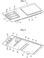
Fig. 3] Fig. 3 is a perspective view made by omitting some electrical components fromFig. 2 . - [
Fig. 4] Fig. 4 is a perspective view when viewed from a lower side inFig. 3 . - [
Fig. 5] Fig. 5 is a schematically cross-sectional view of a portion having a bus bar inFig. 3 . - [
Fig. 6] Fig. 6 is a perspective view showing a third embodiment and being equivalent toFig. 2 . - [
Fig. 7] Fig. 7 is a schematically cross-sectional view showing the third embodiment and being equivalent toFig. 5 . - [
Fig. 8] Fig. 8 is an exploded perspective view of a portion including a bus bar according to a fifth embodiment of the present invention. - [
Fig. 9] Fig. 9 is a cross-sectional view of a partitioned electrical insulation sheet, including bus bars, in the fifth embodiment. - [
Fig. 10] Fig. 10 is a side view of an inverter module according to a sixth embodiment of the present invention. - Hereinafter, embodiments for carrying out the present invention will be described in detail with reference to the drawings.
-
Fig. 1 is a perspective view of a mechanically-electrically integrated electrical rotating apparatus according to a first embodiment of the present invention. Ahousing 1 of the electrical rotating apparatus includes a motor portion 3 having an almost cylindrical shape, aninverter portion 5 having an almost rectangular parallelepiped shape and integrally provided on an upper side, inFig. 1 , of a cylindrically-shaped portion of the motor portion 3, and acover 7 covering over an upper portion of theinverter portion 5. - A three-phase AC motor (hereinafter, merely called as the motor) 8 as an electrical rotating device is housed in the motor portion 3. An
inverter 9 as an electric power conversion device is housed in a portion, above theinverter portion 5, covered by thecover 7. Namely, thehousing 1 integrally houses themotor 8 and theinverter 9. - The
inverter 9 includes asmoothing capacitor 11, apower module 13 having power semiconductor elements and so on as electronic components. Theinverter 9 is attached onto an upper surface, on an opposite side to themotor 8, of atray 15 as an attachment member. A rectangular bottom wall is provided at theinverter portion 5 of thehousing 1 in order to put thetray 15 thereon and then fix it therewith. - The
tray 15 is configured of a rectangular plate member. A material of thetray 15 is metal that is composed of an electrically conductive material, resin or ceramic that is composed of an electrically nonconductive material, or the like. Aninverter module 17 as shown inFig. 2 is configured by mounting the above-mentioned plural electronic components as inverter components on thetray 15. - Three
bus bars 19 as electrically conductive connecting members are attached to thetray 15 at positions on an opposite side to thesmoothing capacitor 11. The threebus bars 19 configure electric power supply terminals for supplying electric power to themotor 8, and are provided so as to be associated with U, V and W phases of themotor 8, respectively. - An
electric current sensor 21 is provided on thebus bars 19 at a position adjacent to thepower module 13. As shown inFig. 3 in which some electronic components are omitted in comparison withFig. 2 ,sensor connecting terminals 23 are provided, so as to protrude upward, at ends of thebus bars 19 on a side of the electriccurrent sensor 21, respectively. The electriccurrent sensor 21 is connected with thebus bars 19 via thesensor connecting terminals 23. - The
electric current sensor 21 is connected with threeterminals 25 led out from thepower module 13. According to this, the electriccurrent sensor 21 detects electric currents flowing from theterminals 25 of thepower module 13 toward thebus bars 19. - Here, the
tray 15 is made of metal that is composed of an electrically conductive material. Therefore, anelectrical insulation sheet 27 as an electrically insulating member such as an electrically insulating paper is provided between themetallic tray 15 and thebus bars 19 in order to get electrical insulation. Theelectrical insulation sheet 27 is formed in an almost square shape to include the whole of the threebus bars 19, and, for example, fixed with thetray 15 and thebus bars 19 by adhesion. -
Terminal holes 19a with which terminal members that are not shown in the drawings are connected and fixed are formed at ends of thebus bars 19 on an opposite side to theelectric current sensor 21. The terminal members not shown in the drawings are connected with themotor 8. As shown inFig. 4 , openedholes 15a that are sufficiently larger than theterminal holes 19a are formed at positions, on thetray 15, so as to be associated with theterminal holes 19a. According to this, the terminal members not shown in the drawings and connected with themotor 8 and themetallic tray 15 are distanced from each other so as to be in a non-contacting state. Opened holes whose diameter is almost equal to that of the openedholes 15a are formed on theelectrical insulation sheet 27 so as to be associated with theterminal holes 19a. - The
smoothing capacitor 11 shown in a rectangular parallelepiped shape is attached onto an electricallyconductive plate 29 having a rectangular shape shown inFig. 3 , and anelectrical insulation sheet 31 as an electrically insulating member is provided between the electricallyconductive plate 29 and thetray 15. Theelectrical insulation sheet 31 is formed, as a whole, in a rectangular shape slightly larger than that of the electricallyconductive plate 29 so that its outer circumferential edge expands outward from an outer circumferential edge of the electricallyconductive plate 29. Theelectrical insulation sheet 31 is fixed with thetray 15 and the electricallyconductive plate 29 by adhesion, for example. - As shown in
Fig. 2 , portions of the electricallyconductive plate 29 and theelectrical insulation sheet 31 that are protrude from thesmoothing capacitor 11 toward thepower module 13 are located under a portion of thepower module 13. According to this, thesmoothing capacitor 11 and thepower module 13 are electrically connected with each other via the electricallyconductive plate 29. - The
power module 13 is fixed on thetray 15 by fasteners, adhesion or the like in a state where its switching elements are molded in resin. A portion of thepower module 13 that is associated with the electricallyconductive plate 29 doesn't form the resin molded portion, and the portion that doesn't form the resin molded portion is electrically connected with thesmoothing capacitor 11. - As shown in
Fig. 4 , a waterchannel forming member 33 is contacted and fixed with thetray 15 on a side of themotor 8. The waterchannel forming member 33 includes an opening portion that opens at its side facing to thetray 15, and a traycooling water channel 35 is formed between it and thetray 15 by contacting and fixing the opening portion to a surface (bottom surface) of thetray 15 to configure acooler 36 as a cooling portion. - The water
channel forming member 33 includes a first mainchannel forming portion 33a, a second mainchannel forming portion 33b, and a third mainchannel forming portion 33c, each of which is formed parallel to a short side of therectangular tray 15. The first mainchannel forming portion 33a and the second mainchannel forming portion 33b are connected with each other by a first connectingchannel forming portion 33d at their ends on one side. The second mainchannel forming portion 33b and the third mainchannel forming portion 33c are connected with each other by a second connectingchannel forming portion 33e at their ends on the opposite side. - Therefore, the water
channel forming member 33 is formed in a serpentine shape. The traycooling water channel 35 is also formed in a serpentine shape so as to be associated with the shape of the waterchannel forming member 33. Aflange 33f is formed along an entire of a circumferential edge of the serpentine waterchannel forming member 33. Theflange 33f is contacted and fixed with thetray 15 by adhesion or the like in a sealing state. - A cooling
water inlet pipe 37 is connected to a vicinity of an end of the first mainchannel forming portion 33a on an opposite side to the first connectingchannel forming portion 33d. On the other hand, a coolingwater outlet pipe 39 is connected to a vicinity of an end of the third mainchannel forming portion 33c on an opposite side to the second connectingchannel forming portion 33e. - Cooling water is supplied from outside to the cooling
water inlet pipe 37 by a cooling water pump that is not shown in the drawing, and then flows through the tray coolingwater channel 35. The cooling water as a cooling medium flows through the tray coolingwater channel 35 from the first mainchannel forming portion 33a toward the third mainchannel forming portion 33c, and then is discharged from the coolingwater outlet pipe 39 to the outside of the cooler 36. - The cooling water discharged to the outside of the cooler 36 cools the
motor 8 while passing through a cooling water channel(s) that is not shown in the drawings and provided in a wall of the motor portion 3 of thehousing 1. The cooling water that has cooled themotor 8 is discharged to the outside of thehousing 1. - An entire of the
tray 15 including the waterchannel forming member 33 may be covered by a laminated film in a state where the smoothingcapacitor 11, thepower module 13 and the electric current sensor 12 are not yet attached thereto. At that time, the laminated film covers the bus bars 19 and the electricallyconductive plate 29 excluding their electrically conductive portions. Further, the laminated film covers the waterchannel forming member 33 excluding the coolingwater inlet pipe 37 and the coolingwater outlet pipe 39. -
Fig. 5 is a schematically cross-sectional view of a portion having thebus bar 19 shown inFig. 3 in the configuration including the laminated film. In this case, the waterchannel forming member 33, the coolingwater 43, thetray 15, theelectrical insulation sheet 27, and thebus bar 19 exist between the upper and lowerlaminated films laminated film 41b. - In the present embodiment, as shown in
Fig. 5 , the coolingwater 43 efficiently cools an entire of thetray 15 by directly contacting with the bottom surface of thetray 15 on the opposite side to the bus bars 19. Since thetray 15 is cooled, theinverter 9 that includes electronic components on thetray 15 such as the bus bars 19, the smoothingcapacitor 11 and thepower module 13 can be cooled effectively. - In addition, there may be a case where heats generated at a coil of the
motor 8 transfer to the inverter 9 (the power module 13) through the bus bars 19. Since thetray 15 is cooled in such a case as explained above, the bus bars 19 are cooled via theelectrical insulation sheet 27 and thereby the heats generated at themotor 8 can be restricted from transferring to the inverter 9 (the power module 13). Therefore, temperature of the inverter 9 (the power module 13) can be restricted from highly increasing. - Since the bus bars 19 are cooled and then their temperatures can be restricted from highly increasing, detection errors, caused by the high temperature, of the electric
current sensor 21 connected with the bus bars 19 can be restricted and then its output gets stable and detection accuracy of the electric currents is improved. In addition, the temperatures of the bus bars 19 are restricted from highly increasing, so that their electrical resistances can be restricted to be low when the electric currents are applied thereto and thereby reliability can be improved. - In the present embodiment, the
tray 15 is made of metal that is an electrically conductive material and theelectrical insulation sheet 27 is disposed between thetray 15 and the bus bars 19. Therefore, cooling of the bus bars 19 can be ensured while electrically insulating thetray 15 from the bus bars 19 by theelectrical insulation sheet 27. Since thetray 15 is made of metal whose thermal resistance is relatively low, heats of the bus bars 19 can be efficiently radiated to the cooler 36 through thetray 15. In addition, by electrically insulating thetray 15 from the bus bars 19 by use of theelectrical insulation sheet 27, thetray 15 can be electrically insulated also from the inverter 9 (the power module 13) easily. - Further in the present embodiment, the water
channel forming member 33 includes the opening portion that opens at its side facing to thetray 15, and the opening portion is contacted and fixed with the surface (bottom surface) of thetray 15. A cooling medium storage chamber that storages the cooling medium is formed inside the opening portion. According to this, the cooling medium flowing to the cooling medium storage chamber in the waterchannel forming member 33 directly cools thetray 15, and thereby thetray 15 can be effectively cooled. - Furthermore in the above-explained configuration, an electrically insulating paper is exemplified as the
electrical insulation sheets tray 15 from the bus bars 19 or from the electricallyconductive plate 29. - As a second embodiment of the present invention, described will be a case where the
tray 15 is composed of an electrically nonconductive material such as resin and ceramic. In this case, theelectrical insulation sheet 27 inFig .5 is not needed. Also theelectrical insulation sheet 31 on the side of the smoothingcapacitor 11 is not also needed. - Therefore, in the second embodiment, the number of components can be reduced due to the lack of the need for the
electrical insulation sheets conductive plate 29 can be enhanced to restrict the temperatures of the bus bars 19 and theinverter 9 from highly increasing more effectively. The temperatures of the bus bars 19 can be restricted from highly increasing more effectively due to the enhancement of the cooling effect with respect to the bus bars 19, and thereby the detection accuracy of the electric currents by the electriccurrent sensor 21 is further improved. -
Fig. 6 is a perspective view showing a third embodiment and being equivalent toFig. 2 . In the third embodiment, ametallic member 45 as a heat radiation member is provided above opposite sides of the bus bars 19 to thetray 15 in an electrically insulated state. Specifically,electrical insulation sheets 47 such as electrically insulating papers that provide electrical insulation are interposed between themetallic member 45 composed of an electrically conductive material and the bus bars 19. Theelectrical insulation sheets 47 are fixed with themetallic member 45 and the bus bars 19 by adhesives, for example. - The
metallic member 45 extends along a parallel alignment direction of the threebus bars 19, and includes aprotrusion 45a at each of its both ends. Lower ends of theprotrusions 45a are contacted and fixed with a surface of thetray 15 by adhesives, for example. -
Fig. 7 is a schematically cross-sectional view showing the third embodiment and being equivalent toFig. 5 , and a cross-sectional view when viewing themetallic member 45 from a side of theterminal hole 19a of thebus bar 19 on thetray 15. In this case, it takes a structure in which themetallic member 45 and theelectrical insulation sheet 47 are further provided between thebus bar 19 and the upperlaminated film 41a in addition to that inFig. 5 . Note that the electrical insulation sheet(s) 47 may be configured integrally with theelectrical insulation sheet 27. - In the third embodiment, the
metallic member 45 is cooled by thetray 15 that is cooled by the coolingwater 43. Here, the heats of the bus bars 19 are radiated to themetallic member 45 through theelectrical insulation sheet 47. Therefore, the bus bars 19 are cooled by themetallic member 45 from their opposite-side surfaces to thetray 15 in addition to being cooled by thetray 15 via theelectrical insulation sheet 27. Therefore, the cooling effect of the bus bars 19 is further improved to restrict, more effectively, the temperatures of the bus bars 19 from highly increasing, and the detection accuracy of the electric currents by the electriccurrent sensor 21 is further improved. - In the third embodiment, the
metallic member 45 is composed of an electrically conductive material, and theelectrical insulation sheets 47 are provided between themetallic member 45 and the bus bars 19. Therefore, the cooling of the bus bars 19 can be ensured while electrically insulating themetallic member 45 from the bus bars 19 by theelectrical insulation sheets 47. - As a fourth embodiment of the present invention, resin or ceramic composed of an electrically nonconductive material may be used instead of the
metallic member 45 as the heat radiation member. In this case, theelectrical insulation sheets 47 inFig. 7 are not needed. According to this, the number of the components can be reduced and the cooling effect of the bus bars 19 can be enhanced further. - Note that the
protrusions 45a of themetallic member 45 may be in a state where they are not contacted with thetray 15 and distanced from it. In this case, themetallic member 45 is not cooled by thetray 15, but themetallic member 45 may be cooled by another cooling member that is not shown in the drawings. In addition, themetallic member 45 may be cooled by ambient air, i.e. air-cooled by expanding themetallic member 45 to outer sides without contacting it with thetray 15. - In addition, heat radiation grease may be pasted between the
tray 15 and theprotrusions 45a of themetallic member 45, between themetallic member 45 and theelectrical insulation sheets 47, and between theelectrical insulation sheets 47 and the bus bars 19. The heat radiation grease is thermally conductive grease having superior heat radiation characteristics, and can reduce thermal resistances to improve heat radiation effects by being pasted on a thermally conductive surface(s) -
Fig. 8 andFig. 9 show a fifth embodiment. In the fifth embodiment, a partitionedelectrical insulation sheet 49 is used instead of theelectrical insulation sheet 27 in the first embodiment shown inFig. 3 . Other configurations are identical to those in the first embodiment. - The partitioned
electrical insulation sheet 49 includesvertical walls 49b on aflat portion 49a having a flat planar shape. Thevertical walls 49b include outer wall 49a1 that surrounds a whole of the threebus bars 19 and partition walls 49b2 each of which is located between the bus bars 19 adjacent to each other to separate the adjacent bus bars 19 from each other. As shown inFig. 9 , a height of the outer wall 49a1 and the partition walls 49b2 from theflat portion 49a is almost identical to a thickness of the bus bar(s) 19. - The three
bus bars 19 are accommodated in three areas surrounded by the outer wall 49a1 and the partition walls 49b2. According to this, the threebus bars 19 are arranged in an aligned state on the partitionedelectrical insulation sheet 49, and the adjacent ones of them are electrically insulated from each other by the partition wall(s) 49b2. - In the fifth embodiment, the plural bus bars 19 are provided and the partition wall 49b2 that is an electrically insulating member is provided between the adjacent bus bars 19. Therefore, the plural bus bars 19 can be electrically insulated from each other with certainty.
- Since the bus bars 19 adjacent to each other can be electrically insulated from each other by the partition wall 49b2, they can be arranged on the
tray 15 so as to make a gap between them narrower. According to this, a mount area on thetray 15 required for the bus bars 19 can be made small, and thereby down-sizing of an entire of theinverter module 17 and also down-sizing of an entire of a motor apparatus as the electrical rotating apparatus can be achieved. - A contact area of the bus bars 19 with the partitioned
electrical insulation sheet 49 is made larger by contacting their side surfaces with thevertical walls 49b than that in the case where only their bottom surfaces are contacted with theelectrical insulation sheet 27 as shown inFig. 3 . Therefore, the heats of the bus bars 19 can be radiated effectively to thetray 15 via the partitionedelectrical insulation sheet 49. In addition, the bus bars 19 are accommodated in the three areas surrounded by the outer wall 49a1 and the partition walls 49b2 in a state where they are aligned therein, and thereby works for installing them on thetray 15 can be easily done. -
Fig. 10 shows a sixth embodiment. In the sixth embodiment, a heat pipe(s) 51 is attached to the bottom surface of thetray 15 instead of the cooler 36 including the waterchannel forming member 33 inFig. 4 . Theheat pipe 51 includes a condensingportion 51a on a side in association with the smoothingcapacitor 11, and an evaporatingportion 51b on a side in association with the bus bars 19 and thepower module 13 that are especially needed to be cooled. - The
power module 13 and the bus bars 19 can be cooled similarly to the case of providing the cooler 36 by radiating their heats to the evaporatingportion 51b of theheat pipe 51. - The embodiments of the present invention are described above, but these embodiments are mere examples described to make the present invention easily understood, and the present invention is not limited to the above embodiments. The technical scope of the present invention is not limited to specific technical matters disclosed in the above embodiments, and includes modifications, changes, alternative techniques easily derived from them.
- For example, in the case where the
tray 15 is made of metal that is composed of an electrically conductive material, only its portions contacting with the bus bars 19 may be configured of an electrically insulating member. - In addition, the present invention can be applied not only to the
inverter 9 but also to a DC-DC converter as the electric power conversion device, and the present invention can be applied to not only to themotor 8 but also to a generator as an electrical rotating device. Further, a Peltier element(s) may be used as the cooling portion. - The present invention is applied to a mechanically-electrically integrated electrical rotating apparatus in which an electrical rotating device and an electric power conversion device are integrally housed in its housing.
-
- 1 housing
- 8 motor (electrical rotating device)
- 9 inverter (electric power conversion device)
- 13 power module (electronic component)
- 15 tray (attachment member)
- 19 bus bar (electrically conductive connecting member)
- 27, 47 electrical insulation sheet (electrically insulating member)
- 36 cooler (cooling portion)
- 45 metallic member (heat radiation member)
- 49b2 partition wall of partitioned electrical insulation sheet (electrically insulating member)
- 51 heat pipe (cooling portion)
Claims (8)
- A mechanically-electrically integrated electrical rotating apparatus comprising:an electrical rotating device;an electric power conversion device connected with the electrical rotating device;a housing that integrally houses the electrical rotating device and the electric power conversion device;an electrically conductive connecting member that is attached to an attachment member in an electrically insulated state from the attachment member on an opposite side of the attachment member to the electrical rotating device and is connected with an electronic component that configures of the electric power conversion device; anda cooling portion that is attached to the attachment member on a side of the electrical rotating device and cools the electronic component and the electrically conductive connecting member.
- The mechanically-electrically integrated electrical rotating apparatus according to claim 1, wherein
an opening portion is provided at at least part of the cooling portion on a side of the attachment member, and
the attachment member is provided at the opening portion. - The mechanically-electrically integrated electrical rotating apparatus according to claim 1 or 2, wherein
the attachment member is composed of an electrically conductive material, and
an electrically insulating member is provided between the attachment member and the electrically conductive connecting member. - The mechanically-electrically integrated electrical rotating apparatus according to claim 1 or 2, wherein
the attachment member is composed of an electrically nonconductive member. - The mechanically-electrically integrated electrical rotating apparatus according to any one of claims 1 to 4, wherein
a heat radiation member is provided on the electrically conductive connecting member in an electrically insulated state on an opposite side to the attachment member. - The mechanically-electrically integrated electrical rotating apparatus according to claim 5, wherein
a heat radiation member is composed of an electrically conductive material, and
an electrically insulating member is provided between the heat radiation member and the electrically conductive connecting member. - The mechanically-electrically integrated electrical rotating apparatus according to claim 5, wherein
the heat radiation member is composed of an electrically nonconductive material.
characterized by. - The mechanically-electrically integrated electrical rotating apparatus according to any one of claims 1 to 7, wherein
the electrically conductive connecting member is provided in a plurality, and
an electrically insulating member is provided between the electrically conductive members adjacent to each other.
Applications Claiming Priority (1)
| Application Number | Priority Date | Filing Date | Title |
|---|---|---|---|
| PCT/JP2015/065116 WO2016189658A1 (en) | 2015-05-26 | 2015-05-26 | Mechatronically integrated rotary electric machine |
Publications (3)
| Publication Number | Publication Date |
|---|---|
| EP3306790A1 true EP3306790A1 (en) | 2018-04-11 |
| EP3306790A4 EP3306790A4 (en) | 2018-08-01 |
| EP3306790B1 EP3306790B1 (en) | 2021-07-28 |
Family
ID=57394066
Family Applications (1)
| Application Number | Title | Priority Date | Filing Date |
|---|---|---|---|
| EP15893293.9A Active EP3306790B1 (en) | 2015-05-26 | 2015-05-26 | Mechatronically integrated rotary electric machine |
Country Status (10)
| Country | Link |
|---|---|
| US (1) | US10361608B2 (en) |
| EP (1) | EP3306790B1 (en) |
| JP (1) | JP6409968B2 (en) |
| KR (1) | KR101968852B1 (en) |
| CN (1) | CN107710563B (en) |
| BR (1) | BR112017025208B1 (en) |
| CA (1) | CA2986743C (en) |
| MX (1) | MX368087B (en) |
| RU (1) | RU2658635C1 (en) |
| WO (1) | WO2016189658A1 (en) |
Families Citing this family (18)
| Publication number | Priority date | Publication date | Assignee | Title |
|---|---|---|---|---|
| DE102014019433A1 (en) * | 2014-12-22 | 2016-06-23 | Audi Ag | Electronic assembly for an electric motor of a single-wheel drive of a motor vehicle, independent wheel drive and motor vehicle |
| CN108233820B (en) * | 2016-12-16 | 2024-06-11 | 上海电驱动股份有限公司 | Integrated electrical module for BSG motor controller |
| WO2019208244A1 (en) * | 2018-04-25 | 2019-10-31 | 日本電産株式会社 | Motor unit |
| CN110784068A (en) * | 2018-07-27 | 2020-02-11 | 台达电子工业股份有限公司 | Water-cooled motor driver integrated machine |
| DE102018215889A1 (en) * | 2018-09-19 | 2020-03-19 | Robert Bosch Gmbh | Insulating device with coolant line |
| FR3090182B1 (en) * | 2018-12-14 | 2021-01-01 | Valeo Siemens Eautomotive France Sas | Electrical equipment comprising an insulating film folded back on itself |
| JP7225032B2 (en) * | 2019-06-03 | 2023-02-20 | 三菱重工サーマルシステムズ株式会社 | Switching element unit and electric compressor |
| JP7432322B2 (en) * | 2019-08-27 | 2024-02-16 | 株式会社Subaru | motor device |
| JP7208124B2 (en) * | 2019-09-20 | 2023-01-18 | 日立Astemo株式会社 | Power converter and motor-integrated power converter |
| US11313359B2 (en) * | 2019-10-01 | 2022-04-26 | St9 Gas And Oil, Llc | Electric drive pump for well stimulation |
| US10888036B1 (en) * | 2019-12-18 | 2021-01-05 | Toyota Motor Engineering & Manufacturing North America, Inc. | Thermal management assemblies for electronic assemblies circumferentially mounted on a motor |
| DE102020114299B4 (en) | 2020-05-28 | 2022-03-10 | Schaeffler Technologies AG & Co. KG | Balcony support for connecting an inverter to an electrical machine |
| EP4254740A4 (en) * | 2020-11-25 | 2024-01-10 | Nissan Motor Co., Ltd. | Inverter-integrated motor |
| JP2022162704A (en) * | 2021-04-13 | 2022-10-25 | 株式会社デンソー | Rotary electric machine, and vehicle loading rotary electric machine |
| JP2023110968A (en) * | 2022-01-31 | 2023-08-10 | 三菱電機株式会社 | Rotating electric machine unit |
| JPWO2025004286A1 (en) * | 2023-06-29 | 2025-01-02 | ||
| DE102023207803A1 (en) * | 2023-08-14 | 2025-02-20 | Robert Bosch Gesellschaft mit beschränkter Haftung | Assembly with carrier plate and method for assembling a assembly with carrier plate |
| WO2026094274A1 (en) * | 2024-11-01 | 2026-05-07 | Astemo株式会社 | Drive device |
Family Cites Families (22)
| Publication number | Priority date | Publication date | Assignee | Title |
|---|---|---|---|---|
| DE19817333C5 (en) * | 1998-04-18 | 2007-04-26 | Conti Temic Microelectronic Gmbh | Electric drive unit consisting of electric motor and electronic module |
| DE60331611D1 (en) * | 2002-09-13 | 2010-04-15 | Aisin Aw Co | drive unit |
| CN100334793C (en) * | 2002-09-13 | 2007-08-29 | 爱信艾达株式会社 | drive unit |
| JP4144465B2 (en) | 2003-07-18 | 2008-09-03 | 株式会社デンソー | Inverter-integrated electric compressor for vehicles |
| JP2005168133A (en) | 2003-12-01 | 2005-06-23 | Mitsuba Corp | Electric motor |
| JP2005237141A (en) * | 2004-02-20 | 2005-09-02 | Toyota Motor Corp | Inverter and method for manufacturing inverter |
| RU64447U1 (en) * | 2007-02-19 | 2007-06-27 | Общество с ограниченной ответственностью "Центртехкомплект" | AUTOMATIC AC DRIVE REGULATOR |
| US8429957B2 (en) * | 2008-05-02 | 2013-04-30 | Envirotest Systems Holdings Corp. | System and method for quantifying the presence of components in the exhaust of commercial and/or heavy-duty vehicles |
| JP5169764B2 (en) | 2008-11-19 | 2013-03-27 | トヨタ自動車株式会社 | Power converter |
| JP5492599B2 (en) | 2010-02-26 | 2014-05-14 | 日立オートモティブシステムズ株式会社 | Rotating electrical machine system |
| JP5400687B2 (en) * | 2010-04-09 | 2014-01-29 | トヨタ自動車株式会社 | High-voltage equipment integrated motor |
| KR20120006309A (en) | 2010-07-12 | 2012-01-18 | 현대모비스 주식회사 | Inverter output busbar module in vehicle |
| JP5384569B2 (en) * | 2011-07-07 | 2014-01-08 | 日立オートモティブシステムズ株式会社 | Electronic control unit |
| JP5259884B1 (en) * | 2011-09-29 | 2013-08-07 | 株式会社安川電機 | Motor drive device and vehicle |
| JP5594275B2 (en) * | 2011-11-10 | 2014-09-24 | 株式会社安川電機 | Rotating electric machine |
| JP5917102B2 (en) * | 2011-11-15 | 2016-05-11 | 日立オートモティブシステムズ株式会社 | Inverter device, electric drive system |
| JP5773904B2 (en) * | 2012-02-07 | 2015-09-02 | 三菱電機株式会社 | Electrical box and air conditioner |
| JP5464224B2 (en) | 2012-03-14 | 2014-04-09 | 株式会社安川電機 | Motor drive device and vehicle |
| JP2013192367A (en) * | 2012-03-14 | 2013-09-26 | Hitachi Automotive Systems Ltd | Electric power conversion apparatus |
| JP5836879B2 (en) * | 2012-05-01 | 2015-12-24 | 日立オートモティブシステムズ株式会社 | Inverter device |
| JP5825310B2 (en) * | 2013-09-05 | 2015-12-02 | 株式会社安川電機 | Motor drive device and vehicle |
| JP6838853B2 (en) | 2014-11-14 | 2021-03-03 | 日産自動車株式会社 | Rotating electrical system |
-
2015
- 2015-05-26 BR BR112017025208-2A patent/BR112017025208B1/en not_active IP Right Cessation
- 2015-05-26 KR KR1020177034048A patent/KR101968852B1/en not_active Expired - Fee Related
- 2015-05-26 CA CA2986743A patent/CA2986743C/en active Active
- 2015-05-26 RU RU2017145538A patent/RU2658635C1/en active
- 2015-05-26 US US15/576,397 patent/US10361608B2/en active Active
- 2015-05-26 JP JP2017520128A patent/JP6409968B2/en active Active
- 2015-05-26 WO PCT/JP2015/065116 patent/WO2016189658A1/en not_active Ceased
- 2015-05-26 MX MX2017014681A patent/MX368087B/en active IP Right Grant
- 2015-05-26 EP EP15893293.9A patent/EP3306790B1/en active Active
- 2015-05-26 CN CN201580080345.5A patent/CN107710563B/en active Active
Also Published As
| Publication number | Publication date |
|---|---|
| RU2658635C1 (en) | 2018-06-22 |
| EP3306790B1 (en) | 2021-07-28 |
| KR101968852B1 (en) | 2019-04-12 |
| BR112017025208B1 (en) | 2022-06-28 |
| MX368087B (en) | 2019-09-19 |
| CN107710563B (en) | 2020-06-30 |
| CA2986743A1 (en) | 2016-12-01 |
| CA2986743C (en) | 2018-12-11 |
| US20180152079A1 (en) | 2018-05-31 |
| JP6409968B2 (en) | 2018-10-24 |
| CN107710563A (en) | 2018-02-16 |
| EP3306790A4 (en) | 2018-08-01 |
| JPWO2016189658A1 (en) | 2018-03-01 |
| WO2016189658A1 (en) | 2016-12-01 |
| KR20170140334A (en) | 2017-12-20 |
| US10361608B2 (en) | 2019-07-23 |
| BR112017025208A2 (en) | 2018-08-07 |
| MX2017014681A (en) | 2018-01-24 |
Similar Documents
| Publication | Publication Date | Title |
|---|---|---|
| CA2986743C (en) | Mechanically-electrically integrated electrical rotating apparatus | |
| US11509196B2 (en) | Motor vehicle and power converter device for a motor vehicle | |
| JP6856682B2 (en) | Methods and systems for cooling power electronics systems built into batteries | |
| US10156239B2 (en) | Inverter-integrated electrical compressor | |
| US11464141B2 (en) | Power converter device for a vehicle, and vehicle | |
| KR101936281B1 (en) | Systems and methods for cooling of power electronic devices | |
| EP3604942B1 (en) | Refrigeration cycle device | |
| CN111788678A (en) | Cooling unit for cooling power components | |
| JP2015053776A (en) | Electric power conversion system | |
| JP6999777B1 (en) | Power converter | |
| JP2019033624A (en) | Power converter | |
| CN112313869A (en) | Power conversion device | |
| JP6824370B1 (en) | Rotating machine | |
| JP2018054499A (en) | Load device and load application method | |
| JP2013025948A (en) | Battery module | |
| JP5707910B2 (en) | Stacked cooler | |
| WO2017002693A1 (en) | Electric compressor | |
| CN215580872U (en) | Capacitance module, power conversion device, and vehicle | |
| JP5195815B2 (en) | Electric equipment cooling device | |
| JP6785721B2 (en) | Inverter device with integrated DCDC converter. | |
| CN120628347A (en) | IGBT temperature measuring mechanism, control device and compressor |
Legal Events
| Date | Code | Title | Description |
|---|---|---|---|
| STAA | Information on the status of an ep patent application or granted ep patent |
Free format text: STATUS: THE INTERNATIONAL PUBLICATION HAS BEEN MADE |
|
| PUAI | Public reference made under article 153(3) epc to a published international application that has entered the european phase |
Free format text: ORIGINAL CODE: 0009012 |
|
| STAA | Information on the status of an ep patent application or granted ep patent |
Free format text: STATUS: REQUEST FOR EXAMINATION WAS MADE |
|
| 17P | Request for examination filed |
Effective date: 20171220 |
|
| AK | Designated contracting states |
Kind code of ref document: A1 Designated state(s): AL AT BE BG CH CY CZ DE DK EE ES FI FR GB GR HR HU IE IS IT LI LT LU LV MC MK MT NL NO PL PT RO RS SE SI SK SM TR |
|
| AX | Request for extension of the european patent |
Extension state: BA ME |
|
| A4 | Supplementary search report drawn up and despatched |
Effective date: 20180628 |
|
| RIC1 | Information provided on ipc code assigned before grant |
Ipc: H02K 11/27 20160101ALI20180622BHEP Ipc: H02K 11/00 20160101ALI20180622BHEP Ipc: H02M 7/48 20070101ALI20180622BHEP Ipc: H02K 9/19 20060101AFI20180622BHEP |
|
| DAV | Request for validation of the european patent (deleted) | ||
| DAX | Request for extension of the european patent (deleted) | ||
| STAA | Information on the status of an ep patent application or granted ep patent |
Free format text: STATUS: EXAMINATION IS IN PROGRESS |
|
| 17Q | First examination report despatched |
Effective date: 20190313 |
|
| REG | Reference to a national code |
Ref country code: DE Ref legal event code: R079 Ref document number: 602015071819 Country of ref document: DE Free format text: PREVIOUS MAIN CLASS: H02K0009190000 Ipc: H02K0005200000 |
|
| RIC1 | Information provided on ipc code assigned before grant |
Ipc: H02K 9/19 20060101ALI20210217BHEP Ipc: H02K 5/20 20060101AFI20210217BHEP Ipc: H02M 7/48 20070101ALI20210217BHEP Ipc: H02K 11/27 20160101ALI20210217BHEP Ipc: H02K 11/33 20160101ALI20210217BHEP |
|
| GRAP | Despatch of communication of intention to grant a patent |
Free format text: ORIGINAL CODE: EPIDOSNIGR1 |
|
| STAA | Information on the status of an ep patent application or granted ep patent |
Free format text: STATUS: GRANT OF PATENT IS INTENDED |
|
| INTG | Intention to grant announced |
Effective date: 20210517 |
|
| GRAS | Grant fee paid |
Free format text: ORIGINAL CODE: EPIDOSNIGR3 |
|
| GRAA | (expected) grant |
Free format text: ORIGINAL CODE: 0009210 |
|
| STAA | Information on the status of an ep patent application or granted ep patent |
Free format text: STATUS: THE PATENT HAS BEEN GRANTED |
|
| AK | Designated contracting states |
Kind code of ref document: B1 Designated state(s): AL AT BE BG CH CY CZ DE DK EE ES FI FR GB GR HR HU IE IS IT LI LT LU LV MC MK MT NL NO PL PT RO RS SE SI SK SM TR |
|
| REG | Reference to a national code |
Ref country code: GB Ref legal event code: FG4D |
|
| REG | Reference to a national code |
Ref country code: CH Ref legal event code: EP |
|
| REG | Reference to a national code |
Ref country code: AT Ref legal event code: REF Ref document number: 1415598 Country of ref document: AT Kind code of ref document: T Effective date: 20210815 |
|
| REG | Reference to a national code |
Ref country code: IE Ref legal event code: FG4D |
|
| REG | Reference to a national code |
Ref country code: DE Ref legal event code: R096 Ref document number: 602015071819 Country of ref document: DE |
|
| REG | Reference to a national code |
Ref country code: LT Ref legal event code: MG9D |
|
| REG | Reference to a national code |
Ref country code: NL Ref legal event code: MP Effective date: 20210728 |
|
| REG | Reference to a national code |
Ref country code: AT Ref legal event code: MK05 Ref document number: 1415598 Country of ref document: AT Kind code of ref document: T Effective date: 20210728 |
|
| PG25 | Lapsed in a contracting state [announced via postgrant information from national office to epo] |
Ref country code: HR Free format text: LAPSE BECAUSE OF FAILURE TO SUBMIT A TRANSLATION OF THE DESCRIPTION OR TO PAY THE FEE WITHIN THE PRESCRIBED TIME-LIMIT Effective date: 20210728 Ref country code: RS Free format text: LAPSE BECAUSE OF FAILURE TO SUBMIT A TRANSLATION OF THE DESCRIPTION OR TO PAY THE FEE WITHIN THE PRESCRIBED TIME-LIMIT Effective date: 20210728 Ref country code: SE Free format text: LAPSE BECAUSE OF FAILURE TO SUBMIT A TRANSLATION OF THE DESCRIPTION OR TO PAY THE FEE WITHIN THE PRESCRIBED TIME-LIMIT Effective date: 20210728 Ref country code: NO Free format text: LAPSE BECAUSE OF FAILURE TO SUBMIT A TRANSLATION OF THE DESCRIPTION OR TO PAY THE FEE WITHIN THE PRESCRIBED TIME-LIMIT Effective date: 20211028 Ref country code: NL Free format text: LAPSE BECAUSE OF FAILURE TO SUBMIT A TRANSLATION OF THE DESCRIPTION OR TO PAY THE FEE WITHIN THE PRESCRIBED TIME-LIMIT Effective date: 20210728 Ref country code: PT Free format text: LAPSE BECAUSE OF FAILURE TO SUBMIT A TRANSLATION OF THE DESCRIPTION OR TO PAY THE FEE WITHIN THE PRESCRIBED TIME-LIMIT Effective date: 20211129 Ref country code: ES Free format text: LAPSE BECAUSE OF FAILURE TO SUBMIT A TRANSLATION OF THE DESCRIPTION OR TO PAY THE FEE WITHIN THE PRESCRIBED TIME-LIMIT Effective date: 20210728 Ref country code: FI Free format text: LAPSE BECAUSE OF FAILURE TO SUBMIT A TRANSLATION OF THE DESCRIPTION OR TO PAY THE FEE WITHIN THE PRESCRIBED TIME-LIMIT Effective date: 20210728 Ref country code: BG Free format text: LAPSE BECAUSE OF FAILURE TO SUBMIT A TRANSLATION OF THE DESCRIPTION OR TO PAY THE FEE WITHIN THE PRESCRIBED TIME-LIMIT Effective date: 20211028 Ref country code: AT Free format text: LAPSE BECAUSE OF FAILURE TO SUBMIT A TRANSLATION OF THE DESCRIPTION OR TO PAY THE FEE WITHIN THE PRESCRIBED TIME-LIMIT Effective date: 20210728 Ref country code: LT Free format text: LAPSE BECAUSE OF FAILURE TO SUBMIT A TRANSLATION OF THE DESCRIPTION OR TO PAY THE FEE WITHIN THE PRESCRIBED TIME-LIMIT Effective date: 20210728 |
|
| PG25 | Lapsed in a contracting state [announced via postgrant information from national office to epo] |
Ref country code: PL Free format text: LAPSE BECAUSE OF FAILURE TO SUBMIT A TRANSLATION OF THE DESCRIPTION OR TO PAY THE FEE WITHIN THE PRESCRIBED TIME-LIMIT Effective date: 20210728 Ref country code: LV Free format text: LAPSE BECAUSE OF FAILURE TO SUBMIT A TRANSLATION OF THE DESCRIPTION OR TO PAY THE FEE WITHIN THE PRESCRIBED TIME-LIMIT Effective date: 20210728 Ref country code: GR Free format text: LAPSE BECAUSE OF FAILURE TO SUBMIT A TRANSLATION OF THE DESCRIPTION OR TO PAY THE FEE WITHIN THE PRESCRIBED TIME-LIMIT Effective date: 20211029 |
|
| PG25 | Lapsed in a contracting state [announced via postgrant information from national office to epo] |
Ref country code: DK Free format text: LAPSE BECAUSE OF FAILURE TO SUBMIT A TRANSLATION OF THE DESCRIPTION OR TO PAY THE FEE WITHIN THE PRESCRIBED TIME-LIMIT Effective date: 20210728 |
|
| REG | Reference to a national code |
Ref country code: DE Ref legal event code: R097 Ref document number: 602015071819 Country of ref document: DE |
|
| PG25 | Lapsed in a contracting state [announced via postgrant information from national office to epo] |
Ref country code: SM Free format text: LAPSE BECAUSE OF FAILURE TO SUBMIT A TRANSLATION OF THE DESCRIPTION OR TO PAY THE FEE WITHIN THE PRESCRIBED TIME-LIMIT Effective date: 20210728 Ref country code: SK Free format text: LAPSE BECAUSE OF FAILURE TO SUBMIT A TRANSLATION OF THE DESCRIPTION OR TO PAY THE FEE WITHIN THE PRESCRIBED TIME-LIMIT Effective date: 20210728 Ref country code: RO Free format text: LAPSE BECAUSE OF FAILURE TO SUBMIT A TRANSLATION OF THE DESCRIPTION OR TO PAY THE FEE WITHIN THE PRESCRIBED TIME-LIMIT Effective date: 20210728 Ref country code: EE Free format text: LAPSE BECAUSE OF FAILURE TO SUBMIT A TRANSLATION OF THE DESCRIPTION OR TO PAY THE FEE WITHIN THE PRESCRIBED TIME-LIMIT Effective date: 20210728 Ref country code: CZ Free format text: LAPSE BECAUSE OF FAILURE TO SUBMIT A TRANSLATION OF THE DESCRIPTION OR TO PAY THE FEE WITHIN THE PRESCRIBED TIME-LIMIT Effective date: 20210728 Ref country code: AL Free format text: LAPSE BECAUSE OF FAILURE TO SUBMIT A TRANSLATION OF THE DESCRIPTION OR TO PAY THE FEE WITHIN THE PRESCRIBED TIME-LIMIT Effective date: 20210728 |
|
| PLBE | No opposition filed within time limit |
Free format text: ORIGINAL CODE: 0009261 |
|
| STAA | Information on the status of an ep patent application or granted ep patent |
Free format text: STATUS: NO OPPOSITION FILED WITHIN TIME LIMIT |
|
| 26N | No opposition filed |
Effective date: 20220429 |
|
| PG25 | Lapsed in a contracting state [announced via postgrant information from national office to epo] |
Ref country code: IT Free format text: LAPSE BECAUSE OF FAILURE TO SUBMIT A TRANSLATION OF THE DESCRIPTION OR TO PAY THE FEE WITHIN THE PRESCRIBED TIME-LIMIT Effective date: 20210728 |
|
| REG | Reference to a national code |
Ref country code: CH Ref legal event code: PL |
|
| REG | Reference to a national code |
Ref country code: BE Ref legal event code: MM Effective date: 20220531 |
|
| PG25 | Lapsed in a contracting state [announced via postgrant information from national office to epo] |
Ref country code: MC Free format text: LAPSE BECAUSE OF FAILURE TO SUBMIT A TRANSLATION OF THE DESCRIPTION OR TO PAY THE FEE WITHIN THE PRESCRIBED TIME-LIMIT Effective date: 20210728 Ref country code: LU Free format text: LAPSE BECAUSE OF NON-PAYMENT OF DUE FEES Effective date: 20220526 Ref country code: LI Free format text: LAPSE BECAUSE OF NON-PAYMENT OF DUE FEES Effective date: 20220531 Ref country code: CH Free format text: LAPSE BECAUSE OF NON-PAYMENT OF DUE FEES Effective date: 20220531 |
|
| PG25 | Lapsed in a contracting state [announced via postgrant information from national office to epo] |
Ref country code: IE Free format text: LAPSE BECAUSE OF NON-PAYMENT OF DUE FEES Effective date: 20220526 |
|
| PG25 | Lapsed in a contracting state [announced via postgrant information from national office to epo] |
Ref country code: BE Free format text: LAPSE BECAUSE OF NON-PAYMENT OF DUE FEES Effective date: 20220531 |
|
| PG25 | Lapsed in a contracting state [announced via postgrant information from national office to epo] |
Ref country code: HU Free format text: LAPSE BECAUSE OF FAILURE TO SUBMIT A TRANSLATION OF THE DESCRIPTION OR TO PAY THE FEE WITHIN THE PRESCRIBED TIME-LIMIT; INVALID AB INITIO Effective date: 20150526 |
|
| PG25 | Lapsed in a contracting state [announced via postgrant information from national office to epo] |
Ref country code: MK Free format text: LAPSE BECAUSE OF FAILURE TO SUBMIT A TRANSLATION OF THE DESCRIPTION OR TO PAY THE FEE WITHIN THE PRESCRIBED TIME-LIMIT Effective date: 20210728 Ref country code: CY Free format text: LAPSE BECAUSE OF FAILURE TO SUBMIT A TRANSLATION OF THE DESCRIPTION OR TO PAY THE FEE WITHIN THE PRESCRIBED TIME-LIMIT Effective date: 20210728 |
|
| PG25 | Lapsed in a contracting state [announced via postgrant information from national office to epo] |
Ref country code: TR Free format text: LAPSE BECAUSE OF FAILURE TO SUBMIT A TRANSLATION OF THE DESCRIPTION OR TO PAY THE FEE WITHIN THE PRESCRIBED TIME-LIMIT Effective date: 20210728 |
|
| PG25 | Lapsed in a contracting state [announced via postgrant information from national office to epo] |
Ref country code: MT Free format text: LAPSE BECAUSE OF FAILURE TO SUBMIT A TRANSLATION OF THE DESCRIPTION OR TO PAY THE FEE WITHIN THE PRESCRIBED TIME-LIMIT Effective date: 20210728 |
|
| PGFP | Annual fee paid to national office [announced via postgrant information from national office to epo] |
Ref country code: DE Payment date: 20250423 Year of fee payment: 11 |
|
| PGFP | Annual fee paid to national office [announced via postgrant information from national office to epo] |
Ref country code: FR Payment date: 20250423 Year of fee payment: 11 |
|
| PGFP | Annual fee paid to national office [announced via postgrant information from national office to epo] |
Ref country code: GB Payment date: 20260317 Year of fee payment: 12 |