WO2016189658A1 - Mechatronically integrated rotary electric machine - Google Patents
Mechatronically integrated rotary electric machine Download PDFInfo
- Publication number
- WO2016189658A1 WO2016189658A1 PCT/JP2015/065116 JP2015065116W WO2016189658A1 WO 2016189658 A1 WO2016189658 A1 WO 2016189658A1 JP 2015065116 W JP2015065116 W JP 2015065116W WO 2016189658 A1 WO2016189658 A1 WO 2016189658A1
- Authority
- WO
- WIPO (PCT)
- Prior art keywords
- rotating electrical
- electrical machine
- tray
- conductive
- bus bar
- Prior art date
Links
Images


Classifications
-
- H—ELECTRICITY
- H02—GENERATION; CONVERSION OR DISTRIBUTION OF ELECTRIC POWER
- H02K—DYNAMO-ELECTRIC MACHINES
- H02K9/00—Arrangements for cooling or ventilating
- H02K9/19—Arrangements for cooling or ventilating for machines with closed casing and closed-circuit cooling using a liquid cooling medium, e.g. oil
-
- H—ELECTRICITY
- H02—GENERATION; CONVERSION OR DISTRIBUTION OF ELECTRIC POWER
- H02M—APPARATUS FOR CONVERSION BETWEEN AC AND AC, BETWEEN AC AND DC, OR BETWEEN DC AND DC, AND FOR USE WITH MAINS OR SIMILAR POWER SUPPLY SYSTEMS; CONVERSION OF DC OR AC INPUT POWER INTO SURGE OUTPUT POWER; CONTROL OR REGULATION THEREOF
- H02M7/00—Conversion of ac power input into dc power output; Conversion of dc power input into ac power output
- H02M7/42—Conversion of dc power input into ac power output without possibility of reversal
- H02M7/44—Conversion of dc power input into ac power output without possibility of reversal by static converters
- H02M7/48—Conversion of dc power input into ac power output without possibility of reversal by static converters using discharge tubes with control electrode or semiconductor devices with control electrode
-
- H—ELECTRICITY
- H02—GENERATION; CONVERSION OR DISTRIBUTION OF ELECTRIC POWER
- H02K—DYNAMO-ELECTRIC MACHINES
- H02K11/00—Structural association of dynamo-electric machines with electric components or with devices for shielding, monitoring or protection
-
- H—ELECTRICITY
- H02—GENERATION; CONVERSION OR DISTRIBUTION OF ELECTRIC POWER
- H02K—DYNAMO-ELECTRIC MACHINES
- H02K11/00—Structural association of dynamo-electric machines with electric components or with devices for shielding, monitoring or protection
- H02K11/20—Structural association of dynamo-electric machines with electric components or with devices for shielding, monitoring or protection for measuring, monitoring, testing, protecting or switching
- H02K11/27—Devices for sensing current, or actuated thereby
-
- H—ELECTRICITY
- H02—GENERATION; CONVERSION OR DISTRIBUTION OF ELECTRIC POWER
- H02K—DYNAMO-ELECTRIC MACHINES
- H02K11/00—Structural association of dynamo-electric machines with electric components or with devices for shielding, monitoring or protection
- H02K11/30—Structural association with control circuits or drive circuits
- H02K11/33—Drive circuits, e.g. power electronics
-
- H—ELECTRICITY
- H02—GENERATION; CONVERSION OR DISTRIBUTION OF ELECTRIC POWER
- H02K—DYNAMO-ELECTRIC MACHINES
- H02K5/00—Casings; Enclosures; Supports
- H02K5/04—Casings or enclosures characterised by the shape, form or construction thereof
- H02K5/20—Casings or enclosures characterised by the shape, form or construction thereof with channels or ducts for flow of cooling medium
- H02K5/203—Casings or enclosures characterised by the shape, form or construction thereof with channels or ducts for flow of cooling medium specially adapted for liquids, e.g. cooling jackets
-
- H—ELECTRICITY
- H02—GENERATION; CONVERSION OR DISTRIBUTION OF ELECTRIC POWER
- H02K—DYNAMO-ELECTRIC MACHINES
- H02K9/00—Arrangements for cooling or ventilating
- H02K9/22—Arrangements for cooling or ventilating by solid heat conducting material embedded in, or arranged in contact with, the stator or rotor, e.g. heat bridges
-
- H—ELECTRICITY
- H05—ELECTRIC TECHNIQUES NOT OTHERWISE PROVIDED FOR
- H05K—PRINTED CIRCUITS; CASINGS OR CONSTRUCTIONAL DETAILS OF ELECTRIC APPARATUS; MANUFACTURE OF ASSEMBLAGES OF ELECTRICAL COMPONENTS
- H05K7/00—Constructional details common to different types of electric apparatus
- H05K7/20—Modifications to facilitate cooling, ventilating, or heating
- H05K7/2029—Modifications to facilitate cooling, ventilating, or heating using a liquid coolant with phase change in electronic enclosures
- H05K7/20336—Heat pipes, e.g. wicks or capillary pumps
-
- H—ELECTRICITY
- H05—ELECTRIC TECHNIQUES NOT OTHERWISE PROVIDED FOR
- H05K—PRINTED CIRCUITS; CASINGS OR CONSTRUCTIONAL DETAILS OF ELECTRIC APPARATUS; MANUFACTURE OF ASSEMBLAGES OF ELECTRICAL COMPONENTS
- H05K7/00—Constructional details common to different types of electric apparatus
- H05K7/20—Modifications to facilitate cooling, ventilating, or heating
- H05K7/2089—Modifications to facilitate cooling, ventilating, or heating for power electronics, e.g. for inverters for controlling motor
- H05K7/20936—Liquid coolant with phase change
-
- H—ELECTRICITY
- H02—GENERATION; CONVERSION OR DISTRIBUTION OF ELECTRIC POWER
- H02K—DYNAMO-ELECTRIC MACHINES
- H02K5/00—Casings; Enclosures; Supports
- H02K5/04—Casings or enclosures characterised by the shape, form or construction thereof
- H02K5/20—Casings or enclosures characterised by the shape, form or construction thereof with channels or ducts for flow of cooling medium
- H02K5/207—Casings or enclosures characterised by the shape, form or construction thereof with channels or ducts for flow of cooling medium with openings in the casing specially adapted for ambient air
-
- H—ELECTRICITY
- H02—GENERATION; CONVERSION OR DISTRIBUTION OF ELECTRIC POWER
- H02K—DYNAMO-ELECTRIC MACHINES
- H02K5/00—Casings; Enclosures; Supports
- H02K5/04—Casings or enclosures characterised by the shape, form or construction thereof
- H02K5/22—Auxiliary parts of casings not covered by groups H02K5/06-H02K5/20, e.g. shaped to form connection boxes or terminal boxes
- H02K5/225—Terminal boxes or connection arrangements
Definitions
- the present invention relates to an electromechanical integrated type rotating electrical machine apparatus in which a rotating electrical machine and a power converter are integrally housed in a housing.
- Patent Document 1 A structure in which an inverter is mounted on a mounting seat provided in a housing when a motor that is a rotating electrical machine and an inverter that is a power converter are integrally housed in a housing is known (see Patent Document 1).
- Patent Document 1 In order to suppress the high temperature of the inverter, the technique of Patent Document 1 cools the housing with a low-temperature gas refrigerant when the compressor is operating, and cools the inverter on the mounting seat with this cold heat.
- an object of the present invention is to suppress the high temperature of the power conversion device due to the heat generated in the rotating electrical machine.
- the present invention is a mechanical / electrical integrated type rotary electric machine device including a rotary electric machine, a power converter, and a housing that integrally accommodates the rotary electric machine and the power converter, and the power converter is opposite to the rotary electric machine.
- An attachment member attached to the side is provided.
- a conductive connection member connected to electronic components constituting the power conversion device is provided on the opposite side of the mounting member from the rotating electrical machine in a state of being electrically insulated from the mounting member.
- a cooling unit for cooling the electronic component and the conductive member is provided on the rotating electrical machine side of the mounting member.
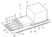
- FIG. 1 is a perspective view of a rotating electrical machine apparatus according to the first embodiment of the present invention.
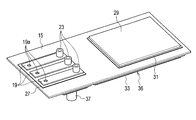
- FIG. 2 is a perspective view of an inverter module used in the rotating electrical machine apparatus of FIG.
- FIG. 3 is a perspective view in which electronic components are omitted from
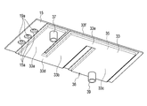
- FIG. 4 is a perspective view seen from the lower side of FIG.
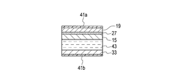
- FIG. 5 is a schematic cross-sectional view of a portion including the bus bar of FIG.
- FIG. 6 is a perspective view corresponding to FIG. 2 according to the third embodiment of the present invention.
- FIG. 7 is a schematic cross-sectional view corresponding to FIG. 5 according to the third embodiment.
- FIG. 8 is an exploded perspective view of a portion including a bus bar according to the fifth embodiment of the present invention.
- FIG. 9 is a cross-sectional view including the bus bar of the insulating sheet with partition walls in the fifth embodiment.
- FIG. 10 is a side view of an inverter module according to the sixth embodiment of the present invention.
- FIG. 1 is a perspective view of an electromechanically integrated rotating electrical machine apparatus according to the first embodiment of the present invention.
- a housing 1 of a rotating electrical machine apparatus includes a substantially cylindrical motor portion 3, an inverter portion 5 having a substantially rectangular parallelepiped shape integrally provided on the upper side of the cylindrical portion of the motor portion 3 in FIG. 1, and an inverter portion 5. And a cover 7 for covering the upper part.
- a three-phase AC motor (hereinafter simply referred to as a motor) 8 as a rotating electric machine is accommodated.
- An inverter 9 as a power conversion device is accommodated in a portion of the inverter unit 5 covered with the cover 7. That is, the housing 1 integrally accommodates the motor 8 and the inverter 9.
- the inverter 9 includes a smoothing capacitor 11, a power module 13 having a power semiconductor element, and the like as electronic components.
- the inverter 9 is attached to the upper surface opposite to the motor 8 of the tray 15 as an attachment member.
- the inverter portion 5 of the housing 1 is provided with a rectangular bottom wall for mounting and fixing the tray 15.
- the tray 15 is composed of a rectangular plate member.
- the material of the tray 15 is a metal made of a conductive member, a resin made of a non-conductive member, ceramic, or the like.
- An inverter module 17 as shown in FIG. 2 is configured by mounting a plurality of the above-described electronic components, which are inverter components, on the tray 15.
- Three bus bars 19 as conductive connecting members are attached to the position on the opposite side of the smoothing capacitor 11 on the tray 15.
- the three bus bars 19 constitute power supply terminals that supply power to the motor 8, and are provided corresponding to the U, V, and W phases of the motor 8.
- a current sensor 21 is provided at a position near the power module 13 of the bus bar 19. As shown in FIG. 3 in which electronic components are omitted from FIG. 2, a sensor connection terminal 23 is provided at the end of the bus bar 19 on the current sensor 21 side so as to protrude upward. The current sensor 21 is connected to the bus bar 19 via the sensor connection terminal 23.
- the current sensor 21 is connected to three terminals 25 drawn from the power module 13. Thereby, the current sensor 21 detects a current flowing from the terminal 25 of the power module 13 toward the bus bar 19.
- the tray 15 here is made of metal made of a conductive member.
- an insulating sheet 27 as an electrical insulating member such as insulating paper is provided between the metal tray 15 and the bus bar 19 in order to achieve electrical insulation.
- the insulating sheet 27 is formed in a substantially square shape including the whole of the three bus bars 19 and is fixed to the tray 15 and the bus bar 19 by, for example, adhesion.
- a terminal hole 19a to which a terminal member (not shown) is connected and fixed is formed at the end of the bus bar 19 opposite to the current sensor 21.
- a terminal member (not shown) is connected to the motor 8 side.
- the tray 15 at a position corresponding to the terminal hole 19a has an opening 15a that is sufficiently larger than the terminal hole 19a.
- the terminal member (not shown) connected to the motor 8 side and the metal tray 15 are separated so as to be in a non-contact state.
- an opening hole having substantially the same diameter as the opening hole 15a is formed corresponding to the terminal hole 19a.
- the smoothing capacitor 11 shown in a rectangular parallelepiped shape is mounted on a rectangular conductive plate 29 shown in FIG. 3, and an insulating sheet 31 serving as an electrical insulating member is provided between the conductive plate 29 and the tray 15.
- the insulating sheet 31 has a rectangular shape that is slightly larger than the conductive plate 29 as a whole so that the outer peripheral edge protrudes outside the outer peripheral edge of the conductive plate 29.
- the insulating sheet 31 is fixed to the tray 15 and the conductive plate 29 by adhesion, for example.
- the conductive plate 29 and the insulating sheet 31 are partially protruded from the smoothing capacitor 11 toward the power module 13, and are located below a part of the power module 13. Thereby, the smoothing capacitor 11 and the power module 13 are electrically connected via the conductive plate 29.
- the power module 13 is fixed on the tray 15 with a fastener or an adhesive in a state where a switching element or the like is molded with a resin.
- the power module 13 is electrically connected to the smoothing capacitor 11 by a portion where the resin mold portion is not formed in the portion corresponding to the conductive plate 29 and the resin mold portion is not formed.
- a water channel forming member 33 is joined and fixed to the motor 8 side of the tray 15.
- the water channel forming member 33 includes an opening that opens on the side facing the tray 15, and the tray cooling water passage 35 is formed between the tray 15 and the tray 15 by bonding and fixing the opening to the front surface (back surface) of the tray 15.
- a cooler 36 as a cooling unit is configured.
- the water channel forming member 33 includes a first main passage forming portion 33a, a second main passage forming portion 33b, and a third main passage forming portion 33c that are formed in parallel along the short side portion of the rectangular tray 15.
- the first main passage forming portion 33a and the second main passage forming portion 33b are connected to each other at one end by a first communication passage forming portion 33d.
- the second main passage forming portion 33b and the third main passage forming portion 33c are connected to each other at the end opposite to the first communication passage forming portion 33d by the second communication passage forming portion 33e.
- the water channel forming member 33 is formed in a meandering shape.
- the tray cooling water passage 35 also has a meandering shape.
- a flange 33f is formed over the entire circumference. The flange 33f is joined and fixed to the tray 15 in a sealed state by adhesion or the like.
- a cooling water inlet pipe 37 is connected near the end of the first main passage forming portion 33a opposite to the first communication passage forming portion 33d.
- a cooling water outlet pipe 39 is connected in the vicinity of the end of the third main passage forming portion 33c opposite to the second communication passage forming portion 33e.
- the cooling water inlet pipe 37 is supplied with cooling water from the outside by a cooling water pump (not shown) and flows through the tray cooling water passage 35.
- the cooling water as the cooling medium flows through the tray cooling water passage 35 from the first main passage forming portion 33a toward the third main passage forming portion 33c, and is discharged from the cooling water outlet pipe 39 to the outside of the cooler 36.
- the cooling water discharged to the outside of the cooler 36 cools the motor 8 through a cooling water passage (not shown) provided in the wall portion of the motor portion 3 of the housing 1.
- the cooling water that has cooled the motor 8 is discharged to the outside of the housing 1.
- the entire tray 15 including the water channel forming member 33 in a state before the smoothing capacitor 11, the power module 13, and the current sensor 21 are attached may be covered with a laminate film.
- the laminate film covers the portion of the bus bar 19 and the conductive plate 29 excluding the electrically conductive portion. Further, the laminated film covers the portion other than the cooling water inlet pipe 37 and the cooling water outlet pipe 39 with respect to the water channel forming member 33.
- FIG. 5 is a schematic cross-sectional view of a portion including the bus bar 19 of FIG. 3 in a configuration including the laminate film.
- the water channel forming member 33, the cooling water 43, the tray 15, the insulating sheet 27, and the bus bar 19 exist between the upper and lower laminate films 41a and 41b in this order from the lower laminate film 41b.
- the cooling water 43 directly contacts the back surface of the tray 15 opposite to the bus bar 19 to cool the entire tray 15 more efficiently.
- the bus bar 19 on the tray 15 the inverter 9 including electronic components such as the smoothing capacitor 11 and the power module 13 are also effectively cooled.
- the heat generated in the coil of the motor 8 may be transmitted to the inverter 9 (power module 13) through the bus bar 19.
- the bus bar 19 is cooled via the insulating sheet 27 by cooling the tray 15 as described above, the transmission of the heat generated on the motor 8 side to the inverter 9 (power module 13) is suppressed. it can. Thereby, the high temperature of the inverter 9 (power module 13) can be suppressed.
- the bus bar 19 Since the bus bar 19 is cooled and can suppress the increase in temperature, the current sensor 21 connected to the bus bar 19 can suppress a detection error due to the increase in temperature, and the output is stabilized and the current detection accuracy is increased. Moreover, the bus bar 19 can suppress the electrical resistance at the time of energization low by suppressing high temperature, and reliability improves.
- the tray 15 is made of a metal that is a conductive member, and an insulating sheet 27 is provided between the tray 15 and the bus bar 19. For this reason, cooling of the bus bar 19 can be ensured while electrically insulating the tray 15 and the bus bar 19 by the insulating sheet 27. Since the tray 15 is made of a metal having a relatively low thermal resistance, the heat of the bus bar 19 can be efficiently radiated to the cooler 36 via the tray 15. Further, by electrically insulating the tray 15 and the bus bar 19 by the insulating sheet 27, the tray 15 and the inverter 9 (power module 13) can be easily electrically insulated.
- the water channel forming member 33 includes an opening that opens on the side facing the tray 15, and the opening is bonded and fixed to the front surface (back surface) of the tray 15.
- a refrigerant accommodating space for accommodating a refrigerant is formed inside the opening.
- the insulating paper is exemplified as the insulating sheets 27 and 31 of the present embodiment.
- the insulating paper is not necessarily limited thereto, and any sheet that electrically insulates the tray 15 from the bus bar 19 or the conductive plate 29 may be used. .
- the tray 15 is made of a resin or ceramic made of a non-conductive member.
- the insulating sheet 27 is unnecessary in FIG.
- the insulating sheet 31 on the smoothing capacitor 11 side is also unnecessary.
- the number of parts can be reduced by eliminating the need for the insulating sheets 27 and 31, and the cooling effect on the bus bar 19 and the conductive plate 29 can be increased, further increasing the temperature rise of the bus bar 19 and the inverter 9. Can be suppressed. Since the cooling effect of the bus bar 19 is enhanced, the temperature rise of the bus bar 19 can be further suppressed, and the current detection accuracy of the current sensor 21 is further enhanced.
- FIG. 6 is a perspective view corresponding to FIG. 2 according to the third embodiment of the present invention.
- a metal member 45 as a heat radiating member is provided in an electrically insulated state on the upper side of the bus bar 19 opposite to the tray 15.
- an insulating sheet 47 such as insulating paper that electrically insulates is interposed between the metal member 45 made of a conductive member and the bus bar 19.
- the insulating sheet 47 is fixed between the metal member 45 and the bus bar 19 with, for example, an adhesive.
- the metal member 45 includes protrusions 45a extending along the parallel arrangement direction of the three bus bars 19 and protruding downward at both ends. The lower end of the protrusion 45a is brought into contact with the surface of the tray 15 and fixed by, for example, an adhesive.
- FIG. 7 is a schematic cross-sectional view corresponding to FIG. 5 according to the third embodiment, and is a cross-sectional view when the metal member 45 is viewed from the terminal hole 19 a side of the bus bar 19 of the tray 15.
- a metal member 45 and an insulating sheet 47 are added between the bus bar 19 and the upper laminate film 41a.
- the insulating sheet 47 may be integrated with the insulating sheet 27.
- the metal member 45 is cooled via the tray 15 that is cooled by the cooling water 43.
- the heat of the bus bar 19 is radiated to the metal member 45 through the insulating sheet 47.
- the bus bar 19 is cooled from the tray 15 via the insulating sheet 27 and is also cooled by the metal member 45 from the surface opposite to the tray 15. For this reason, the cooling effect of the bus bar 19 is further improved, the temperature rise of the bus bar 19 can be further suppressed, and the current detection accuracy of the current sensor 21 is further increased.
- the metal member 45 is formed of a conductive member, and an insulating sheet 47 is provided between the metal member 45 and the bus bar 19. For this reason, it is possible to ensure cooling of the bus bar 19 while electrically insulating the metal member 45 and the bus bar 19 by the insulating sheet 47.
- a resin or ceramic made of a non-conductive member may be used instead of the metal member 45 which is a heat radiating member.
- the insulating sheet 47 is unnecessary in FIG. Thereby, the reduction of the number of parts and the cooling effect of the bus bar 19 are further improved.
- the protruding portion 45 a of the metal member 45 may be separated from the tray 15 without being in contact with the tray 15.
- the metal member 45 may be cooled not by the tray 15 but by another cooling member (not shown). Further, the metal member 45 may extend outside without being in contact with the tray 15, and may be cooled by the atmosphere around the metal member 45, so-called air cooling.
- heat radiation grease may be applied between the tray 15 and the protruding portion 45a of the metal member 45, between the metal member 45 and the insulating sheet 47, and between the insulating sheet 47 and the bus bar 19, respectively.
- the heat dissipating grease is a heat conductive grease excellent in heat dissipating property, and by applying to the heat conducting surface, the heat resistance can be lowered and the heat dissipating effect can be further enhanced.
- FIG. 8 and 9 show a fifth embodiment.
- an insulating sheet with partition walls 49 is used instead of the insulating sheet 27 in the first embodiment shown in FIG.
- Other configurations are the same as those of the first embodiment.
- the insulating sheet 49 with a partition wall is provided with a vertical wall 49b on a flat plate portion 49a.
- the vertical wall 49 b includes an outer wall 49 a 1 that surrounds the entire periphery of the three bus bars 19, and a partition wall 49 b 2 that is positioned between the adjacent bus bars 19 and partitions the bus bars 19.
- the height of the outer wall 49 a 1 and the partition wall 49 b 2 from the flat portion 49 a is substantially equal to the plate thickness of the bus bar 19.
- the three bus bars 19 are respectively accommodated in three regions surrounded by the outer wall 49a1 and the partition wall 49b2. Thereby, the three bus bars 19 can be installed in a state of being positioned with respect to the insulating sheet 49 with partition wall, and those adjacent to each other are electrically insulated by the partition wall 49b2.
- a plurality of bus bars 19 are provided, and a partition wall 49b2 serving as an electrically insulating member is provided between the plurality of bus bars 19. Thereby, the electrical insulation of several bus-bars 19 is made more reliably.
- the bus bars 19 adjacent to each other can be electrically insulated by the partition wall 49b2, they can be installed on the tray 15 in a closer state. Thereby, the installation area
- the contact area between the bus bar 19 and the insulating sheet 49 with a partition wall is increased by bringing the peripheral side surface into contact with the vertical wall 49b, as compared with the case where only the bottom surface is in contact with the insulating sheet 27 as shown in FIG. Thereby, the heat of the bus bar 19 can be radiated to the tray 15 more effectively via the insulating sheet 49 with partition walls. Further, since the bus bar 19 can be accommodated in a state of being positioned in three regions surrounded by the outer wall 49a1 and the partition wall 49b2, the installation work on the tray 15 is facilitated.
- FIG. 10 shows a sixth embodiment.
- a heat pipe 51 is attached to the back side of the tray 15 instead of the cooler 36 including the water channel forming member 33 in FIG. 4.
- the side corresponding to the smoothing capacitor 11 is a condensing unit 51a
- the side corresponding to the bus bar 19 or the power module 13 that particularly requires cooling is an evaporating unit 51b.
- the power module 13 and the bus bar 19 are cooled in the same manner as when the cooler 36 is provided by dissipating heat to the evaporation part 51b of the heat pipe 51.
- the tray 15 is made of a metal made of a conductive member
- only the portion in contact with the bus bar 19 may be made of an electrically insulating member.
- the present invention can be applied not only to the inverter 9 as a power converter but also to a DC-DC converter, and the present invention can be applied to a generator as well as the motor 8 as a rotating electric machine.
- a Peltier element may be used as the cooling unit.
- the present invention is applied to an electromechanical integrated rotating electrical machine apparatus in which a rotating electrical machine and a power conversion apparatus are integrally housed in a housing.
Abstract
Description
8 モータ(回転電機)
9 インバータ(電力変換装置)
13 パワーモジュール(電子部品)
15 トレイ(取付部材)
19 バスバー(導電接続部材)
27,47 絶縁シート(電気的絶縁部材)
36 冷却器(冷却部)
45 金属部材(放熱部材)
49b2 仕切壁付絶縁シートの仕切壁(電気的絶縁部材)
51 ヒートパイプ(冷却部) 1 Housing 8 Motor (Rotating electric machine)
9 Inverter (Power converter)
13 Power modules (electronic components)
15 Tray (mounting member)
19 Bus bar (conductive connection member)
27, 47 Insulation sheet (electrical insulation member)
36 Cooler (cooling part)
45 Metal member (Heat dissipation member)
49b2 Partition wall of insulating sheet with partition wall (electrical insulating member)
51 Heat pipe (cooling part)
Claims (8)
- 回転電機と、
回転電機に接続される電力変換装置と、
前記回転電機及び前記電力変換装置を一体的に収容するハウジングと、
前記ハウジングに取り付けられ、前記電力変換装置が前記回転電機と反対側に取り付けられる取付部材と、
前記取付部材の前記回転電機と反対側に、取付部材に対して電気的に絶縁された状態で取り付けられ、前記電力変換装置を構成する電子部品に接続される導電接続部材と、
前記取付部材の前記回転電機側に取り付けられ、前記電子部品及び導電接続部材を冷却する冷却部と、を有することを特徴とする機電一体型の回転電機装置。 Rotating electrical machinery,
A power converter connected to the rotating electrical machine;
A housing that integrally accommodates the rotating electrical machine and the power converter;
An attachment member attached to the housing, wherein the power converter is attached to the opposite side of the rotating electrical machine;
A conductive connection member that is attached to the side opposite to the rotating electrical machine of the attachment member in an electrically insulated state with respect to the attachment member, and is connected to an electronic component that constitutes the power conversion device,
An electro-mechanical-integrated rotating electrical machine apparatus, comprising: a cooling unit that is mounted on the rotating electrical machine side of the mounting member and cools the electronic component and the conductive connection member. - 前記冷却部は前記取付部材側の少なくとも一部に開口部が設けられ、
前記取付部材は前記開口部に設けられることを特徴とする請求項1に記載の機電一体型の回転電機装置。 The cooling part is provided with an opening in at least a part on the mounting member side,
The electromechanical integrated rotating electrical machine apparatus according to claim 1, wherein the attachment member is provided in the opening. - 前記取付部材は導電性部材で構成され、
前記取付部材と前記導電接続部材との間に電気的絶縁部材が設けられていることを特徴とする請求項1または2に記載の機電一体型の回転電機装置。 The mounting member is composed of a conductive member,
3. The electromechanical integrated rotating electrical machine apparatus according to claim 1, wherein an electrically insulating member is provided between the attachment member and the conductive connecting member. - 前記取付部材は非導電性部材で構成されていることを特徴とする請求項1または2に記載の機電一体型の回転電機装置。 3. The electromechanical integrated rotating electrical machine apparatus according to claim 1, wherein the mounting member is made of a non-conductive member.
- 前記導電接続部材の前記取付部材と反対側に、電気的に絶縁された状態で放熱部材が設けられていることを特徴とする請求項1ないし4のいずれか1項に記載の機電一体型の回転電機装置。 5. The electromechanical integrated type according to claim 1, wherein a heat radiating member is provided in an electrically insulated state on a side opposite to the mounting member of the conductive connecting member. Rotating electrical machine device.
- 放熱部材は導電性部材で構成され、
前記放熱部材と前記導電接続部材との間に電気的絶縁部材が設けられていることを特徴とする請求項5に記載の機電一体型の回転電機装置。 The heat dissipation member is composed of a conductive member,
6. The electromechanical integrated rotating electrical machine apparatus according to claim 5, wherein an electrically insulating member is provided between the heat dissipating member and the conductive connecting member. - 前記放熱部材は非導電性部材で構成されていることを特徴とする請求項5に記載の機電一体型の回転電機装置。
ことを特徴とする。 6. The electromechanically integrated rotating electrical machine apparatus according to claim 5, wherein the heat dissipating member is made of a non-conductive member.
It is characterized by that. - 前記導電接続部材は複数設けられ、
前記複数の導電接続部材相互間には電気的絶縁部材が設けられていることを特徴とする請求項1ないし7のいずれか1項に記載の機電一体型の回転電機装置。 A plurality of the conductive connection members are provided,
8. The electromechanically integrated rotating electrical machine apparatus according to claim 1, wherein an electrically insulating member is provided between the plurality of conductive connecting members. 9.
Priority Applications (10)
| Application Number | Priority Date | Filing Date | Title |
|---|---|---|---|
| JP2017520128A JP6409968B2 (en) | 2015-05-26 | 2015-05-26 | Mechanical and electric integrated rotating electrical machine |
| RU2017145538A RU2658635C1 (en) | 2015-05-26 | 2015-05-26 | Mechanical and electrical united electric rotary installation |
| CA2986743A CA2986743C (en) | 2015-05-26 | 2015-05-26 | Mechanically-electrically integrated electrical rotating apparatus |
| US15/576,397 US10361608B2 (en) | 2015-05-26 | 2015-05-26 | Mechanically-electrically integrated electrical rotating apparatus with high cooling performance |
| PCT/JP2015/065116 WO2016189658A1 (en) | 2015-05-26 | 2015-05-26 | Mechatronically integrated rotary electric machine |
| BR112017025208-2A BR112017025208B1 (en) | 2015-05-26 | 2015-05-26 | MECHANICALLY AND ELECTRICALLY INTEGRATED ELECTRICAL ROTATING APPARATUS |
| CN201580080345.5A CN107710563B (en) | 2015-05-26 | 2015-05-26 | Electromechanical integrated rotating electric device |
| MX2017014681A MX368087B (en) | 2015-05-26 | 2015-05-26 | Mechatronically integrated rotary electric machine. |
| KR1020177034048A KR101968852B1 (en) | 2015-05-26 | 2015-05-26 | Mechanically integrated rotating electric machine device |
| EP15893293.9A EP3306790B1 (en) | 2015-05-26 | 2015-05-26 | Mechatronically integrated rotary electric machine |
Applications Claiming Priority (1)
| Application Number | Priority Date | Filing Date | Title |
|---|---|---|---|
| PCT/JP2015/065116 WO2016189658A1 (en) | 2015-05-26 | 2015-05-26 | Mechatronically integrated rotary electric machine |
Publications (1)
| Publication Number | Publication Date |
|---|---|
| WO2016189658A1 true WO2016189658A1 (en) | 2016-12-01 |
Family
ID=57394066
Family Applications (1)
| Application Number | Title | Priority Date | Filing Date |
|---|---|---|---|
| PCT/JP2015/065116 WO2016189658A1 (en) | 2015-05-26 | 2015-05-26 | Mechatronically integrated rotary electric machine |
Country Status (10)
| Country | Link |
|---|---|
| US (1) | US10361608B2 (en) |
| EP (1) | EP3306790B1 (en) |
| JP (1) | JP6409968B2 (en) |
| KR (1) | KR101968852B1 (en) |
| CN (1) | CN107710563B (en) |
| BR (1) | BR112017025208B1 (en) |
| CA (1) | CA2986743C (en) |
| MX (1) | MX368087B (en) |
| RU (1) | RU2658635C1 (en) |
| WO (1) | WO2016189658A1 (en) |
Cited By (3)
| Publication number | Priority date | Publication date | Assignee | Title |
|---|---|---|---|---|
| CN108233820A (en) * | 2016-12-16 | 2018-06-29 | 上海电驱动股份有限公司 | A kind of BSG electric machine controllers integrated electrical module |
| WO2019208245A1 (en) * | 2018-04-25 | 2019-10-31 | 日本電産株式会社 | Motor unit |
| JP7432322B2 (en) | 2019-08-27 | 2024-02-16 | 株式会社Subaru | motor device |
Families Citing this family (8)
| Publication number | Priority date | Publication date | Assignee | Title |
|---|---|---|---|---|
| DE102014019433A1 (en) * | 2014-12-22 | 2016-06-23 | Audi Ag | Electronic assembly for an electric motor of a single-wheel drive of a motor vehicle, independent wheel drive and motor vehicle |
| TW202007555A (en) * | 2018-07-27 | 2020-02-16 | 台達電子工業股份有限公司 | Integrated apparatus of water-cooled motor and driver |
| JP7225032B2 (en) * | 2019-06-03 | 2023-02-20 | 三菱重工サーマルシステムズ株式会社 | Switching element unit and electric compressor |
| JP7208124B2 (en) * | 2019-09-20 | 2023-01-18 | 日立Astemo株式会社 | Power converter and motor-integrated power converter |
| US11313359B2 (en) * | 2019-10-01 | 2022-04-26 | St9 Gas And Oil, Llc | Electric drive pump for well stimulation |
| US10888036B1 (en) * | 2019-12-18 | 2021-01-05 | Toyota Motor Engineering & Manufacturing North America, Inc. | Thermal management assemblies for electronic assemblies circumferentially mounted on a motor |
| DE102020114299B4 (en) | 2020-05-28 | 2022-03-10 | Schaeffler Technologies AG & Co. KG | Balcony support for connecting an inverter to an electrical machine |
| CN116529993A (en) * | 2020-11-25 | 2023-08-01 | 日产自动车株式会社 | Inverter-integrated motor |
Citations (4)
| Publication number | Priority date | Publication date | Assignee | Title |
|---|---|---|---|---|
| JP2005237141A (en) * | 2004-02-20 | 2005-09-02 | Toyota Motor Corp | Inverter and inverter manufacturing method |
| JP2011223744A (en) * | 2010-04-09 | 2011-11-04 | Toyota Motor Corp | Integrated motor with high voltage equipment |
| JP2013162017A (en) * | 2012-02-07 | 2013-08-19 | Mitsubishi Electric Corp | Electric component box and air conditioner |
| JP2013233052A (en) * | 2012-05-01 | 2013-11-14 | Hitachi Automotive Systems Ltd | Inverter device |
Family Cites Families (18)
| Publication number | Priority date | Publication date | Assignee | Title |
|---|---|---|---|---|
| DE19817333C5 (en) * | 1998-04-18 | 2007-04-26 | Conti Temic Microelectronic Gmbh | Electric drive unit consisting of electric motor and electronic module |
| WO2004025807A1 (en) * | 2002-09-13 | 2004-03-25 | Aisin Aw Co., Ltd. | Drive device |
| WO2004025808A1 (en) | 2002-09-13 | 2004-03-25 | Aisin Aw Co., Ltd. | Drive device |
| JP4144465B2 (en) | 2003-07-18 | 2008-09-03 | 株式会社デンソー | Inverter-integrated electric compressor for vehicles |
| JP2005168133A (en) | 2003-12-01 | 2005-06-23 | Mitsuba Corp | Electric motor |
| RU64447U1 (en) * | 2007-02-19 | 2007-06-27 | Общество с ограниченной ответственностью "Центртехкомплект" | AUTOMATIC AC DRIVE REGULATOR |
| US8429957B2 (en) * | 2008-05-02 | 2013-04-30 | Envirotest Systems Holdings Corp. | System and method for quantifying the presence of components in the exhaust of commercial and/or heavy-duty vehicles |
| JP5169764B2 (en) | 2008-11-19 | 2013-03-27 | トヨタ自動車株式会社 | Power converter |
| JP5492599B2 (en) | 2010-02-26 | 2014-05-14 | 日立オートモティブシステムズ株式会社 | Rotating electrical machine system |
| KR20120006309A (en) * | 2010-07-12 | 2012-01-18 | 현대모비스 주식회사 | Inverter output bus bar module of vehicle |
| JP5384569B2 (en) | 2011-07-07 | 2014-01-08 | 日立オートモティブシステムズ株式会社 | Electronic control unit |
| WO2013046412A1 (en) * | 2011-09-29 | 2013-04-04 | 株式会社安川電機 | Motor drive device and vehicle |
| JP5594275B2 (en) * | 2011-11-10 | 2014-09-24 | 株式会社安川電機 | Rotating electric machine |
| JP5917102B2 (en) * | 2011-11-15 | 2016-05-11 | 日立オートモティブシステムズ株式会社 | Inverter device, electric drive system |
| JP5464224B2 (en) * | 2012-03-14 | 2014-04-09 | 株式会社安川電機 | Motor drive device and vehicle |
| JP2013192367A (en) * | 2012-03-14 | 2013-09-26 | Hitachi Automotive Systems Ltd | Electric power conversion apparatus |
| JP5825310B2 (en) * | 2013-09-05 | 2015-12-02 | 株式会社安川電機 | Motor drive device and vehicle |
| JP6838853B2 (en) | 2014-11-14 | 2021-03-03 | 日産自動車株式会社 | Rotating electrical system |
-
2015
- 2015-05-26 EP EP15893293.9A patent/EP3306790B1/en active Active
- 2015-05-26 CN CN201580080345.5A patent/CN107710563B/en active Active
- 2015-05-26 BR BR112017025208-2A patent/BR112017025208B1/en active IP Right Grant
- 2015-05-26 JP JP2017520128A patent/JP6409968B2/en active Active
- 2015-05-26 KR KR1020177034048A patent/KR101968852B1/en active IP Right Grant
- 2015-05-26 US US15/576,397 patent/US10361608B2/en active Active
- 2015-05-26 MX MX2017014681A patent/MX368087B/en active IP Right Grant
- 2015-05-26 CA CA2986743A patent/CA2986743C/en active Active
- 2015-05-26 RU RU2017145538A patent/RU2658635C1/en active
- 2015-05-26 WO PCT/JP2015/065116 patent/WO2016189658A1/en active Application Filing
Patent Citations (4)
| Publication number | Priority date | Publication date | Assignee | Title |
|---|---|---|---|---|
| JP2005237141A (en) * | 2004-02-20 | 2005-09-02 | Toyota Motor Corp | Inverter and inverter manufacturing method |
| JP2011223744A (en) * | 2010-04-09 | 2011-11-04 | Toyota Motor Corp | Integrated motor with high voltage equipment |
| JP2013162017A (en) * | 2012-02-07 | 2013-08-19 | Mitsubishi Electric Corp | Electric component box and air conditioner |
| JP2013233052A (en) * | 2012-05-01 | 2013-11-14 | Hitachi Automotive Systems Ltd | Inverter device |
Non-Patent Citations (1)
| Title |
|---|
| See also references of EP3306790A4 * |
Cited By (3)
| Publication number | Priority date | Publication date | Assignee | Title |
|---|---|---|---|---|
| CN108233820A (en) * | 2016-12-16 | 2018-06-29 | 上海电驱动股份有限公司 | A kind of BSG electric machine controllers integrated electrical module |
| WO2019208245A1 (en) * | 2018-04-25 | 2019-10-31 | 日本電産株式会社 | Motor unit |
| JP7432322B2 (en) | 2019-08-27 | 2024-02-16 | 株式会社Subaru | motor device |
Also Published As
| Publication number | Publication date |
|---|---|
| EP3306790B1 (en) | 2021-07-28 |
| JP6409968B2 (en) | 2018-10-24 |
| JPWO2016189658A1 (en) | 2018-03-01 |
| EP3306790A4 (en) | 2018-08-01 |
| BR112017025208A2 (en) | 2018-08-07 |
| MX2017014681A (en) | 2018-01-24 |
| US10361608B2 (en) | 2019-07-23 |
| KR20170140334A (en) | 2017-12-20 |
| EP3306790A1 (en) | 2018-04-11 |
| RU2658635C1 (en) | 2018-06-22 |
| BR112017025208B1 (en) | 2022-06-28 |
| KR101968852B1 (en) | 2019-04-12 |
| CN107710563A (en) | 2018-02-16 |
| CN107710563B (en) | 2020-06-30 |
| US20180152079A1 (en) | 2018-05-31 |
| CA2986743C (en) | 2018-12-11 |
| MX368087B (en) | 2019-09-19 |
| CA2986743A1 (en) | 2016-12-01 |
Similar Documents
| Publication | Publication Date | Title |
|---|---|---|
| JP6409968B2 (en) | Mechanical and electric integrated rotating electrical machine | |
| US8829669B2 (en) | Semiconductor device | |
| JP5725067B2 (en) | Power converter | |
| JP5861614B2 (en) | High voltage electric device and electric compressor | |
| US11509196B2 (en) | Motor vehicle and power converter device for a motor vehicle | |
| JP4144465B2 (en) | Inverter-integrated electric compressor for vehicles | |
| CN104781554B (en) | Inverter-integrated electric compressor | |
| JP5957396B2 (en) | Double-sided cooling power converter | |
| JP6180857B2 (en) | Power converter | |
| JP2017229174A (en) | Rotary electric machine | |
| JP2017103922A (en) | Power supply unit-integrated rotary electric machine | |
| US11464141B2 (en) | Power converter device for a vehicle, and vehicle | |
| JP6999777B1 (en) | Power converter | |
| JP6945671B2 (en) | Power converter | |
| WO2021053975A1 (en) | Power converter and motor-integrated power converter | |
| WO2019244502A1 (en) | Electric power converter | |
| WO2017002693A1 (en) | Electric compressor | |
| JP5707910B2 (en) | Stacked cooler | |
| JP2017201870A (en) | Rotating electric machine integrated with controller | |
| JP2000152656A (en) | Power converter | |
| JP7366082B2 (en) | power converter | |
| JP7327211B2 (en) | power converter | |
| JP2018207578A (en) | Dc/dc converter integrated inverter device |
Legal Events
| Date | Code | Title | Description |
|---|---|---|---|
| 121 | Ep: the epo has been informed by wipo that ep was designated in this application |
Ref document number: 15893293 Country of ref document: EP Kind code of ref document: A1 |
|
| ENP | Entry into the national phase |
Ref document number: 2017520128 Country of ref document: JP Kind code of ref document: A |
|
| WWE | Wipo information: entry into national phase |
Ref document number: MX/A/2017/014681 Country of ref document: MX |
|
| ENP | Entry into the national phase |
Ref document number: 2986743 Country of ref document: CA |
|
| WWE | Wipo information: entry into national phase |
Ref document number: 15576397 Country of ref document: US |
|
| ENP | Entry into the national phase |
Ref document number: 20177034048 Country of ref document: KR Kind code of ref document: A |
|
| NENP | Non-entry into the national phase |
Ref country code: DE |
|
| WWE | Wipo information: entry into national phase |
Ref document number: 2017145538 Country of ref document: RU |
|
| WWE | Wipo information: entry into national phase |
Ref document number: 2015893293 Country of ref document: EP |
|
| REG | Reference to national code |
Ref country code: BR Ref legal event code: B01A Ref document number: 112017025208 Country of ref document: BR |
|
| ENP | Entry into the national phase |
Ref document number: 112017025208 Country of ref document: BR Kind code of ref document: A2 Effective date: 20171124 |