EP3306301A1 - Vorrichtung zur erkennung von fremdstoffen und verfahren zur erkennung von fremdstoffen - Google Patents
Vorrichtung zur erkennung von fremdstoffen und verfahren zur erkennung von fremdstoffen Download PDFInfo
- Publication number
- EP3306301A1 EP3306301A1 EP16807178.5A EP16807178A EP3306301A1 EP 3306301 A1 EP3306301 A1 EP 3306301A1 EP 16807178 A EP16807178 A EP 16807178A EP 3306301 A1 EP3306301 A1 EP 3306301A1
- Authority
- EP
- European Patent Office
- Prior art keywords
- foreign substance
- impedance
- conversion element
- electromechanical conversion
- substance detection
- Prior art date
- Legal status (The legal status is an assumption and is not a legal conclusion. Google has not performed a legal analysis and makes no representation as to the accuracy of the status listed.)
- Granted
Links
Images


Classifications
-
- G—PHYSICS
- G01—MEASURING; TESTING
- G01N—INVESTIGATING OR ANALYSING MATERIALS BY DETERMINING THEIR CHEMICAL OR PHYSICAL PROPERTIES
- G01N5/00—Analysing materials by weighing, e.g. weighing small particles separated from a gas or liquid
- G01N5/02—Analysing materials by weighing, e.g. weighing small particles separated from a gas or liquid by absorbing or adsorbing components of a material and determining change of weight of the adsorbent, e.g. determining moisture content
-
- F—MECHANICAL ENGINEERING; LIGHTING; HEATING; WEAPONS; BLASTING
- F24—HEATING; RANGES; VENTILATING
- F24D—DOMESTIC- OR SPACE-HEATING SYSTEMS, e.g. CENTRAL HEATING SYSTEMS; DOMESTIC HOT-WATER SUPPLY SYSTEMS; ELEMENTS OR COMPONENTS THEREFOR
- F24D17/00—Domestic hot-water supply systems
- F24D17/02—Domestic hot-water supply systems using heat pumps
-
- F—MECHANICAL ENGINEERING; LIGHTING; HEATING; WEAPONS; BLASTING
- F24—HEATING; RANGES; VENTILATING
- F24D—DOMESTIC- OR SPACE-HEATING SYSTEMS, e.g. CENTRAL HEATING SYSTEMS; DOMESTIC HOT-WATER SUPPLY SYSTEMS; ELEMENTS OR COMPONENTS THEREFOR
- F24D19/00—Details
- F24D19/0092—Devices for preventing or removing corrosion, slime or scale
-
- G—PHYSICS
- G01—MEASURING; TESTING
- G01N—INVESTIGATING OR ANALYSING MATERIALS BY DETERMINING THEIR CHEMICAL OR PHYSICAL PROPERTIES
- G01N27/00—Investigating or analysing materials by the use of electric, electrochemical, or magnetic means
- G01N27/02—Investigating or analysing materials by the use of electric, electrochemical, or magnetic means by investigating impedance
-
- G—PHYSICS
- G01—MEASURING; TESTING
- G01N—INVESTIGATING OR ANALYSING MATERIALS BY DETERMINING THEIR CHEMICAL OR PHYSICAL PROPERTIES
- G01N29/00—Investigating or analysing materials by the use of ultrasonic, sonic or infrasonic waves; Visualisation of the interior of objects by transmitting ultrasonic or sonic waves through the object
- G01N29/02—Analysing fluids
- G01N29/022—Fluid sensors based on microsensors, e.g. quartz crystal-microbalance [QCM], surface acoustic wave [SAW] devices, tuning forks, cantilevers, flexural plate wave [FPW] devices
-
- G—PHYSICS
- G01—MEASURING; TESTING
- G01N—INVESTIGATING OR ANALYSING MATERIALS BY DETERMINING THEIR CHEMICAL OR PHYSICAL PROPERTIES
- G01N29/00—Investigating or analysing materials by the use of ultrasonic, sonic or infrasonic waves; Visualisation of the interior of objects by transmitting ultrasonic or sonic waves through the object
- G01N29/02—Analysing fluids
- G01N29/036—Analysing fluids by measuring frequency or resonance of acoustic waves
-
- G—PHYSICS
- G01—MEASURING; TESTING
- G01N—INVESTIGATING OR ANALYSING MATERIALS BY DETERMINING THEIR CHEMICAL OR PHYSICAL PROPERTIES
- G01N2291/00—Indexing codes associated with group G01N29/00
- G01N2291/01—Indexing codes associated with the measuring variable
- G01N2291/014—Resonance or resonant frequency
-
- G—PHYSICS
- G01—MEASURING; TESTING
- G01N—INVESTIGATING OR ANALYSING MATERIALS BY DETERMINING THEIR CHEMICAL OR PHYSICAL PROPERTIES
- G01N2291/00—Indexing codes associated with group G01N29/00
- G01N2291/02—Indexing codes associated with the analysed material
- G01N2291/025—Change of phase or condition
- G01N2291/0256—Adsorption, desorption, surface mass change, e.g. on biosensors
-
- G—PHYSICS
- G01—MEASURING; TESTING
- G01N—INVESTIGATING OR ANALYSING MATERIALS BY DETERMINING THEIR CHEMICAL OR PHYSICAL PROPERTIES
- G01N2291/00—Indexing codes associated with group G01N29/00
- G01N2291/02—Indexing codes associated with the analysed material
- G01N2291/025—Change of phase or condition
- G01N2291/0258—Structural degradation, e.g. fatigue of composites, ageing of oils
Definitions
- the present invention relates to a foreign substance detection device and a foreign substance detection method, for detecting a foreign substance adhered inside a pipe.
- Heat-pump-type heat exchangers using refrigerant are used in hot-water supply devices, water heaters, air conditioning apparatus, and other such devices.
- heat exchange systems using, as its refrigerant, CO 2 which has a high heat exchange rate, have been commonly used in heat exchangers.
- a hot-water supply system such as a heat-pump-type hot-water supply device, stores clean water (tap water) in a hot-water storage tank, and causes the water stored in the hot-water storage tank to repeatedly circulate through the heat exchange system to obtain boiling water.
- a foreign substance called scale which forms due to the quality of water used, is generated inside the pipes of the hot-water supply device or other such devices, and is adhered on the inner surface of the pipes.
- Scale may be peeled from and reattached to the inside of a pipe, thereby causing clogging of a flow path of the pipe, and such clogging may cause failures in hot-water supply device or other such devices. For this reason, it is necessary to prevent failures due to scale by detecting scale adhered inside a pipe.
- Patent Literature 1 there is disclosed an apparatus configured to receive reflected waves of ultrasonic waves emitted from the outside of a pipe to the inside thereof to measure the thickness of scale adhered on an inner surface of the pipe.
- the inside of the pipe is filled with water, and, by receiving reflected waves reflected at a boundary between an inner wall of the pipe and scale and reflected waves reflected at a boundary between the scale and the water, a foreign substance, such as scale, is detected, and the thickness of the foreign substance is measured.
- Patent Literature 2 there is disclosed an apparatus configured to measure the thickness of scale on the basis of detection signals from an ultrasonic transceiver unit mounted on a pipe.
- Patent Literature 2 by detecting a change in the strength of second- or higher-order harmonic spectrum, a foreign substance, such as scale, is detected, and the thickness of the foreign substance is measured.
- the measurement apparatus disclosed in Patent Literature 1 receives ultrasonic waves that have been reflected multiple times inside the pipe, and as a result, the accuracy in measurement is lowered. Further, the measurement apparatus disclosed in Patent Literature 2 measures a change in the strength of high-order harmonic spectrum. For this reason, when a foreign substance having low acoustic impedance, such as a soft foreign substance, is adhered inside a pipe, the difference in the strength of high-order harmonic spectrum is hardly obtained. Consequently, in Patent Literature 2, it is difficult to detect a foreign substance having low acoustic impedance.
- the present invention has been made to solve the above-mentioned problems, and has an object to provide a foreign substance detection device and a foreign substance detection method, which are capable of detecting a foreign substance with high measurement accuracy.
- adhesion of a foreign substance inside a pipe is detected on the basis of the impedance of the electromechanical conversion element.
- the impedance of the electromechanical conversion element varies depending on a mass load. In this way, a foreign substance is detected on the basis of the mass load, and thus the foreign substance can be detected with high accuracy.
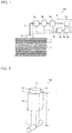
- FIG. 1 is a schematic diagram for illustrating a foreign substance detection device 100 according to Embodiment 1 of the present invention.
- the foreign substance detection device 100 is described with reference to FIG. 1 .
- the foreign substance detection device 100 includes an electromechanical conversion element 4 and a foreign substance detection unit 6.
- the electromechanical conversion element 4 is attached to a pipe 1, and is configured to convert energy electric energy to mechanical energy and convert mechanical energy to electric energy.
- the electromechanical conversion element 4 As the electromechanical conversion element 4, a piezoelectric element 12, a crystal oscillator, a ferrite oscillator, or another element is used.
- the electromechanical conversion element 4 and the foreign substance detection unit 6 are connected by a signal line 5, and transmit and receive signals to and from each other via the signal line 5.
- FIG. 2 is a perspective view for illustrating the foreign substance detection device 100 according to Embodiment 1 of the present invention.
- the foreign substance detection device 100 includes an attachment 20, and the piezoelectric element 12, which serves as the electromechanical conversion element 4, is attached to the pipe 1 by using the attachment 20.
- the piezoelectric element 12 is one example of the electromechanical conversion element 4.
- the attachment 20 is formed of a part that is formed into a rectangular parallelepiped shape and connected to the piezoelectric element 12, and a part that is formed into a rectangular parallelepiped shape and connected to the pipe 1. Both end surfaces of the piezoelectric element 12 are vibration surfaces 13, and each vibration surface 13 is provided with an electrode 14 to which a power source 10 (see FIG. 3 ) is connected. In addition, the signal line 5 is attached to the piezoelectric element 12.
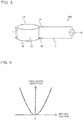
- FIG. 3 is a schematic diagram for illustrating the piezoelectric element 12 in Embodiment 1 of the present invention.
- the piezoelectric element 12 is used as the electromechanical conversion element 4.
- the piezoelectric element 12 is formed into, for example, a cylindrical shape, and both end surfaces thereof are the vibration surfaces 13. Each end surface is provided with the electrode 14, and an alternating-current (AC) voltage is applied between the electrodes 14 from the power source 10 via an electric wire 11.
- AC alternating-current
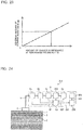
- FIG. 4 is a graph for showing a relationship between an applied voltage and a vibration amplitude of the piezoelectric element 12 in Embodiment 1 of the present invention.
- the horizontal axis indicates the applied voltage
- the vertical axis indicates the vibration amplitude.
- the piezoelectric element 12 performs a contraction movement such that the vibration surfaces 13 vibrate to convert electric energy into mechanical energy.
- Such a piezoelectric element 12 has become widespread, and, for example, lead zirconate titanate or polyvinylidene fluoride (PVDF), which is resin, is used as the material thereof.
- the piezoelectric element 12 has a heat resistant temperature of 80 degrees C or higher, and thus can be used even in a high temperature environment.
- the piezoelectric element 12 is small in size and simple in handling, and has excellent temperature characteristics and electric characteristics.
- the frequency at which the piezoelectric element 12 is most likely to vibrate is determined by the size of the piezoelectric element 12.
- T thickness of the piezoelectric element 12 in an expansion/contraction direction
- f frequency at which vibration is most likely to occur
- C speed of sound passing through the piezoelectric element 12
- the piezoelectric element 12 When the piezoelectric element 12 is driven with a frequency f at which the piezoelectric element 12 is most likely to vibrate, the energy conversion efficiency in converting electric energy into mechanical (vibration) energy increases.
- the frequency f at which vibration is most likely to occur is called “resonance frequency”.
- the resonance frequency f when N is 1 is called “fundamental frequency”.
- the vibration frequency of the piezoelectric element 12 be set with N equal to 1.
- a piezoelectric element 12 having a thickness T of larger than 20 mm It is not easy to manufacture a piezoelectric element 12 having a thickness T of larger than 20 mm. Further, when the thickness of the piezoelectric element 12 is increased, the weight of the piezoelectric element 12 itself is increased, and as a result, the piezoelectric element 12 becomes difficult to handle. In addition, when the thickness of the piezoelectric element 12 is increased, the piezoelectric element 12 requires a large amount of electric energy, that is, a high voltage, to vibrate. For this reason, it is preferred that the thickness T of the piezoelectric element 12 be equal to or less than 20 mm.
- FIG. 5 is a schematic diagram for illustrating a structure that allows the piezoelectric element 12 to operate at low frequency in Embodiment 1 of the present invention.
- a structure is called "Langevin-type oscillator” or “bolt-clamped Langevin-type oscillator”. With this structure, vibration can be generated efficiently at a low voltage.
- the frequency f at which vibration is most likely to occur is a resonance frequency. That is, by adjusting the length L, the resonance frequency can be adjusted. In addition, by increasing the length L, the frequency can be lowered. Even when the length L is increased, the thickness T of the piezoelectric element 12 remains unchanged, and thus a higher voltage is not needed. That is, low-frequency vibration can be generated by using a low voltage.
- the length L is too long, the frequency becomes too low and may be reduced to 20 kHz or less, which is in an audible range, and as a result, the vibration may be noise. Further, when the length L is too long, the size of the foreign substance detection device 100 increases and handleability thereof is impaired. Therefore, it is preferred that the length L be 20 cm or less to ensure that the frequency is 20 kHz or higher.
- the resonance frequency f is proportional to the speed C' of sound, and inversely proportional to the length L.
- a material having a slow sound speed and a material having a long length.
- examples of the speed of sound for metals are given.
- the sound speed of aluminum is 6,320 m/s
- the sound speed of brass is 4,430 m/s
- the sound speed of copper is 4,660 m/s.
- end surfaces of the piezoelectric elements 12 are sandwiched by the metallic blocks 15 and 16, but the end surfaces may be sandwiched by plastic blocks.
- the sound speeds of plastic are described.
- the sound speed of acrylic is 2,730 m/s
- the sound speed of epoxy is 3,070 m/s
- the sound speed of glass fiber is 2,740 m/s.
- the vibration frequency of the piezoelectric element 12 be set with N equal to 1.
- the piezoelectric element 12 requires more energy to increase the vibration amplitude as the frequency increases. For this reason, it is preferred that driving frequency of the piezoelectric element 12 be set low to drive the piezoelectric element 12 by small electric energy. In this case, it is preferred that the frequency be set to 50 MHz or less.
- FIG. 6 is an equivalent circuit diagram of the piezoelectric element 12 in Embodiment 1 of the present invention. As illustrated in FIG. 6 , the piezoelectric element 12 is translated into a diagram of an electric equivalent circuit including a capacitor Cd, a resistor Rm, a coil Lm, and a capacitor Cm. The piezoelectric element 12 is represented by a circuit in which the capacitor Cd is connected in parallel to the resistor Rm, the coil Lm, and the capacitor Cm, which are connected in series.
- the capacitor Cd represents an electrostatic capacitance between both electrodes 14 of the piezoelectric element 12.
- the piezoelectric element 12 is configured in such a manner that a piezoelectric material is sandwiched by two electrodes 14, and hence the piezoelectric element 12 can be considered as a capacitor.
- the resistor Rm represents a load to be applied when the piezoelectric element 12 vibrates, and is called "mechanical resistance”.
- the resistor Rm, the coil Lm, and the capacitor Cm are obtained by implementing the mechanical constants of the piezoelectric element 12 as electric circuit elements, and are determined in accordance with the type, the size, the material, or other properties of the piezoelectric element 12.
- the impedance corresponds to the resistance of a case in which a direct-current (DC) voltage is applied.
- DC direct-current
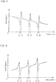
- FIG. 7 is a graph for showing frequency characteristics of the impedance of the piezoelectric element 12 in Embodiment 1 of the present invention.
- the horizontal axis indicates the frequency f
- the vertical axis indicates impedance Z.
- the impedance of a circuit to which an AC voltage is applied corresponds to the resistance of a circuit to which a DC voltage is applied, and represents how difficult current flows.
- the impedance Z has minimum values at frequencies f11, f21, and f31. That is, at the frequencies f11, f21, and f31, current flows easily.
- Such frequencies f11, f21, and f31 are called "resonance frequencies". With the frequency f11 as a fundamental frequency, the frequency f21 is a frequency that is twice the frequency f11, and the frequency f31 is a frequency that is three times the frequency f11. As described above, the resonance frequencies appear at frequencies of an integral multiple of the fundamental frequency.
- the impedance Z has maximum values at frequencies f12, f22, and f32. That is, at the frequencies f12, f22, and f32, current is difficult to flow. Such frequencies f12, f22, and f32 are called "antiresonance frequencies". With the frequency f12 as a fundamental frequency, the frequency f22 is a frequency that is twice the frequency f12, and the frequency f32 is a frequency that is three times the frequency f12.
- the antiresonance frequencies appear at frequencies of an integral multiple of the fundamental frequency.
- resonance phenomena occur among the coil Lm, the capacitor Cm, and the capacitor Cd of FIG. 6 .
- Such resonance phenomena are considered to be resonance phenomena in which a mechanical resonance phenomenon and an electrical resonance phenomenon are combined.
- FIG. 8 is a graph for showing frequency characteristics of admittance of the piezoelectric element 12 in Embodiment 1 of the present invention.
- the horizontal axis indicates the frequency f
- the vertical axis indicates admittance Y.
- the admittance Y of a circuit to which an AC voltage is applied corresponds to the conductance of a circuit to which a DC voltage is applied, and represents how easy current flows.
- the admittance Y has maximum values at frequencies f11, f21, and f31.
- the admittance Y has minimum values at frequencies f12, f22, and f32. That is, at the frequencies f12, f22, and f32, current is difficult to flow. This is the same as FIG. 7 .
- the impedance and the admittance are reciprocals, and therefore the graph of FIG. 8 is a vertically inverted image of the graph of FIG. 7 .
- the piezoelectric element 12 converts electric energy into mechanical energy most efficiently at a resonance frequency. Therefore, the piezoelectric element 12 vibrates with small energy at a resonance frequency. Consequently, at a resonance frequency, the vibration amplitude of the piezoelectric element 12 is easily changed by even a small change in electric energy.
- the piezoelectric element 12 is sensitive to changes in the vibration amplitude, and the electromotive force of the piezoelectric element 12 changes. That is, at a resonance frequency or an antiresonance frequency, the impedance changes easily in response to a change in the resistance value of the resistor Rm of FIG. 6 . Therefore, when a mass load that prevents vibration is applied to the vibration surface 13 of the piezoelectric element 12, the resistance value of the resistor Rm of FIG. 6 increases and the impedance changes.
- the impedance which is an electric characteristic, of the piezoelectric element 12 changes due to converted electric energy.
- the amount of change in the impedance at a resonance frequency increases when the mass load is applied to the vibration surfaces 13.
- the electric energy required for the piezoelectric element 12 to vibrate decreases.
- the amount of change in the impedance with respect to the mass load, which prevents vibration becomes the maximum at the lowest resonance frequency among a plurality of resonance frequencies.
- the amount of change in the impedance with respect to the mass load, which prevents vibration becomes the maximum also at the lowest antiresonance frequency among a plurality of antiresonance frequencies.
- FIG. 9 is a graph for showing frequency characteristics of a phase difference of the piezoelectric element 12 in Embodiment 1 of the present invention.
- the horizontal axis indicates the frequency f
- the vertical axis indicates the phase difference.
- how to determine a resonance frequency and an antiresonance frequency is described. As shown in FIG. 9 , at a resonance frequency or at an antiresonance frequency, the phase difference between the voltage applied to the piezoelectric element 12 and the current flowing to the piezoelectric element 12 is zero.
- a resonance frequency is a frequency at which the impedance of the piezoelectric element 12 becomes a minimum value when the impedance of the piezoelectric element 12 is measured continuously while the frequency of the power source 10 is being continuously changed, and at which the phase difference between the voltage and the current is zero.
- an antiresonance frequency is a frequency at which the impedance of the piezoelectric element 12 becomes a maximum value when the impedance of the piezoelectric element 12 is measured continuously while the frequency of the power source 10 is being continuously changed, and at which the phase difference between the voltage and the current is zero. Resonance frequencies and antiresonance frequencies are obtained when the foreign substance detection device 100 is installed on a pipe 1 in which no foreign substance 2 is adhered.
- the foreign substance detection unit 6 is configured to measure the impedance of the electromechanical conversion element 4, and includes, as illustrated in FIG. 1 , a voltage measurement unit 6a, a current measurement unit 6b, a phase measurement unit 6c, an impedance calculation unit 6d, a detection unit 6g, and a power source 6e.
- the voltage measurement unit 6a is configured to measure an element voltage applied to the electromechanical conversion element 4 when power is supplied from the power source 6e.
- the current measurement unit 6b is configured to measure an element current flowing through the electromechanical conversion element 4 when power is supplied from the power source 6e.
- the phase measurement unit 6c is configured to measure a phase difference between the element voltage measured by the voltage measurement unit 6a and the element current measured by the current measurement unit 6b.
- FIG. 10 is a vector diagram for illustrating the impedance Z in Embodiment 1 of the present invention.
- the voltage V and the current I are treated as complex vectors, and the impedance Z is also a complex vector.
- of impedance is obtained by an expression
- ⁇ (R 2 +X 2 ).
- the phase difference ( ⁇ ) between the voltage and the current is an angle formed by an R component of Z and the Z vector.
- the impedance calculation unit 6d not only calculates the impedance but also calculates the impedance every time the frequency of the power source 6e is changed, thereby measuring a resonance frequency or an antiresonance frequency.
- the capacitor Cm and the coil Lm also vary. Consequently, the change in the measured impedance includes not only a variation of the resistance value of the resistor Rm but also variations of the values of the capacitor Cm and the coil Lm.
- Embodiment 1 a resonance frequency or an antiresonance frequency is measured, and the resonance frequency or the antiresonance frequency is used as the frequency at which the impedance is measured. Therefore, the change in the impedance does not include the variations of the values of the capacitor Cm and the coil Lm, but includes only the variation of resistance value of the resistor Rm.
- the detection unit 6g is configured to detect adhesion of a foreign substance 2 inside the pipe 1 on the basis of the impedance calculated by the impedance calculation unit 6d.
- the power source 6e is configured to supply power to the electromechanical conversion element 4 to cause the electromechanical conversion element 4 to vibrate.
- the impedance calculation unit 6d calculates the impedance on the basis of the phase difference between the element voltage and the element current, the phase difference being measured by the phase measurement unit 6c. At this moment, a resonance called spurious may occur depending on the material or the size of the attachment 20 of the foreign substance detection device 100 illustrated in FIG. 2 . The spurious acts as noise in the calculation of impedance, and thus disturbs detection of a foreign substance.
- FIG. 11 is a graph for showing frequency characteristics of the impedance of the piezoelectric element 12 when spurious occurs in Embodiment 1 of the present invention.
- the horizontal axis indicates frequency (kHz), and the vertical axis indicates magnitude of the impedance ( ⁇ ).
- FIG. 12 is a graph for showing frequency characteristics of the phase difference of the piezoelectric element 12 when spurious occurs in Embodiment 1 of the present invention.
- the horizontal axis indicates frequency (kHz), and the vertical axis indicates phase difference (degree).
- the impedance becomes the minimum at a frequency fN, which is different from an actual resonance frequency fM of the foreign substance detection device 100.
- the phase difference between the element voltage and the element current of the foreign substance detection device 100 is not zero degrees.
- Embodiment 1 by calculating, by the impedance calculation unit 6d, the impedance on the basis of the phase difference, a measurement error caused by noise, such as spurious, can be eliminated.
- the values of the coil Lm and the capacitor Cm of an equivalent circuit of the piezoelectric element 12 shown in FIG. 6 may vary. Therefore, when a plurality of minimum values of impedance are present due to spurious or other reasons, a frequency at which the phase difference between the element voltage and the element current is close to zero degrees is used as a resonance frequency. In addition, when a plurality of maximum values of impedance are present due to spurious or other reasons, a frequency at which the phase difference between the element voltage and the element current is close to zero degrees is used as an antiresonance frequency.
- the impedance is calculated on the basis of the element voltage, the element current, and the phase difference, but the impedance may be calculated on the basis of the element voltage and the element current, and then a resonance frequency may be measured on the basis of the impedance.
- a noise component may be generated due to the shape and the size thereof. When noise is generated, the impedance may become a minimum value at a frequency different from the actual resonance frequency.
- Embodiment 1 by measuring a phase difference by the phase measurement unit 6c, a resonance frequency is determined correctly.
- the voltage measurement unit 6a, the current measurement unit 6b, the phase measurement unit 6c, and the power source 6e are connected via the signal line 5.
- the voltage measurement unit 6a, the current measurement unit 6b, and the phase measurement unit 6c are connected to the impedance calculation unit 6d by transmission lines 6f.
- the impedance calculation unit 6d and the detection unit 6g are connected by a transmission line 6f.
- the foreign substance 2 that is adhered inside the pipe 1 is described.
- the foreign substance 2 called scale, which forms due to the quality of water used, is generated and is adhered on the inner surface of the pipe 1.
- Scale may be peeled from and reattached to the inside of the pipe 1, thereby causing clogging of a flow path of the pipe 1.
- the foreign substance 2 is not limited to scale.
- the foreign substance 2 may be any soft foreign substance.
- Embodiment 1 a foreign substance detection method according to Embodiment 1 is described. First, when power is supplied from the power source 6e to the electromechanical conversion element 4, which is attached to the pipe 1 and converts electric energy into mechanical energy, the element voltage applied to the electromechanical conversion element 4, the element current flowing through the electromechanical conversion element 4, and the phase difference between the element voltage applied to the electromechanical conversion element 4 and the element current flowing through the electromechanical conversion element 4 are measured.
- the impedance is calculated. Then, on the basis of the impedance, the adhesion of a foreign substance 2 inside the pipe 1 is detected.
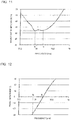
- FIG. 13 is a graph for showing frequency characteristics of the impedance of the piezoelectric element 12 with different mass loads in Embodiment 1 of the present invention.
- the horizontal axis indicates the frequency (kHz)
- the vertical axis indicates the magnitude of the impedance ( ⁇ ).
- FIG. 14 is a graph for showing the relationship between an adhesion amount of a foreign substance 2 and the impedance of the piezoelectric element 12 in Embodiment 1 of the present invention.
- the horizontal axis indicates the adhesion amount (g) of a foreign substance
- the vertical axis indicates the magnitude of the impedance ( ⁇ ) at a resonance frequency.
- the amount of change in the impedance of the piezoelectric element 12 becomes largest at the resonance frequency.
- the resonance frequency is, for example, 81 kHz.
- the impedance of the piezoelectric element 12 at the resonance frequency is measured while the adhesion amount of the foreign substance 2 inside the pipe 1 is being changed, the impedance increases as the adhesion amount of the foreign substance 2 increases.
- the foreign substance detection device 100 detects the adhesion of a foreign substance 2 inside the pipe 1 on the basis of the impedance of the electromechanical conversion element 4.
- the impedance of the electromechanical conversion element 4 changes due to the mass load. That is, the foreign substance detection device 100 detects the adhesion of a foreign substance 2 on the basis of a change in the mass load. Consequently, the measurement accuracy is high, and as a result, a foreign substance 2 having a low acoustic impedance can also be detected.
- the foreign substance detection device 100 can detect even a soft foreign substance 2.
- the foreign substance detection device 100 does not detect reflected waves, and does not measure a change in the strength of a high-order harmonic spectrum. Therefore, the measurement can be performed in a short time, the measurement accuracy is high, and a foreign substance 2 having a low acoustic impedance can also be detected.
- a foreign substance 2 can be measured in a short time, and the measurement accuracy thereof is high. Further, in a case where, as in the related art, the adhesion of a foreign substance 2 is detected on the basis of a change in the spectrum, when a foreign substance 2 having a low acoustic impedance, for example, a soft foreign substance 2, is adhered inside the pipe 1, a difference in the strength of the spectrum is hardly obtained.
- Embodiment 1 even when a soft foreign substance 2 is adhered, a change in the mass inside the pipe 1 is detected on the basis of the change in the impedance of the electromechanical conversion element 4. Consequently, even a foreign substance 2 having a low acoustic impedance can be detected.
- the foreign substance detection unit 6 further includes the phase measurement unit 6c configured to measure the phase difference between the element voltage measured by the voltage measurement unit 6a and the element current measured by the current measurement unit 6b, and the impedance calculation unit 6d is configured to calculate the impedance on the basis of the element voltage, the element current, and the phase difference measured by the phase measurement unit 6c.
- the phase measurement unit 6c configured to measure the phase difference between the element voltage measured by the voltage measurement unit 6a and the element current measured by the current measurement unit 6b
- the impedance calculation unit 6d is configured to calculate the impedance on the basis of the element voltage, the element current, and the phase difference measured by the phase measurement unit 6c.
- the piezoelectric element 12 is used.
- the power source 6e is configured to drive the electromechanical conversion element 4 under a state in which the vibration frequency thereof is a resonance frequency. Consequently, a foreign substance 2 that is adhered inside the pipe 1 and is a mass load preventing vibration of the piezoelectric element 12 can be detected with high accuracy.
- the power source 6e is configured to drive the electromechanical conversion element 4 under a state in which the vibration frequency thereof is the lowest resonance frequency among a plurality of resonance frequencies.
- the impedance calculation unit 6d is configured to measure a resonance frequency of the electromechanical conversion element 4 on the basis of a measurement result of the impedance of the electromechanical conversion element 4. Consequently, the common impedance calculation unit 6d can measure both impedance and resonance frequency.
- the power source 6e is configured to drive the electromechanical conversion element 4 under a state in which the vibration frequency thereof is an antiresonance frequency. Consequently, a foreign substance 2 that is a mass load preventing vibration of the piezoelectric element 12 can be detected with high accuracy.
- the power source 6e is configured to drive the electromechanical conversion element 4 under a state in which the vibration frequency thereof is the lowest antiresonance frequency among a plurality of antiresonance frequencies.
- the impedance calculation unit 6d measures an antiresonance frequency of the electromechanical conversion element 4 on the basis of a measurement result of the impedance of the electromechanical conversion element 4. Consequently, the common impedance calculation unit 6d can measure both impedance and antiresonance frequency.
- the power source 6e is configured to drive the electromechanical conversion element 4 at a vibration frequency, whose phase difference is almost zero degrees. Consequently, even in a case where a plurality of extreme values of impedance are present due to spurious or other reasons, a noise component can be eliminated.
- the signal line 5 of the foreign substance detection device 100 be disconnected from the electromechanical conversion element 4, and that the impedance of a case where a positive electrode and a negative electrode of the signal line 5 are open-circuited and the impedance of a case where the positive electrode and the negative electrode of the signal line 5 are short-circuited be measured.
- noise components that cause reduction in measurement accuracy are measured. Therefore, for example, noise components are subtracted from the actual measurement values when the adhesion amount of a foreign substance is small, and thus a foreign substance can be detected more accurately even when the adhesion amount of the foreign substance is small.
- Open-circuiting the positive electrode and the negative electrode of the signal line 5 and short-circuiting of the positive electrode and the negative electrode thereof are performed manually or automatically.
- the attachment 20 illustrated in FIG. 2 which is used to attach the piezoelectric element 12 to the pipe 1, is in contact with the surface of the pipe 1. It is preferred that, in the attachment 20, the size of the area that comes into contact with the piezoelectric element 12 be between one and two times the size of the area of the vibration surface 13 of the piezoelectric element 12. In addition, an oil, such as grease, may be applied into the contact surface between the piezoelectric element 12 and the attachment 20, and into the contact part between the attachment 20 and the pipe 1. As a result, the accuracy in detecting a foreign substance 2 is improved.
- the length L' of the attachment 20 is set so that the resonance frequency occurs at 81 kHz, for example.
- FIG. 15 is a circuit diagram for illustrating Example 1 of the application of the foreign substance detection device 100 to a hot-water supply device 31 in Embodiment 1 of the present invention.
- the hot-water supply device 31 is connected to a heat pump unit 33, and hot water generated by the heat pump unit 33 is supplied to a bathroom 32.
- the hot-water supply device 31 includes a tank 31a, a heat exchanger 31b, a pump 31c, a mixing valve 31d, a switching valve 31j, the foreign substance detection device 100, and an operation controller 31k.
- the tank 31a is configured to store hot water, and is connected to the heat pump unit 33 by a heat pump pipe 31h.
- the heat exchanger 31b is configured to exchange heat between the water of a bathtub 32a and the hot water of the tank 31a when reheating is performed in the bathtub 32a installed in the bathroom 32.
- the heat exchanger 31b is connected to the tank 31a by a heat exchanger pipe 31g, and connected also to the bathtub 32a by a reheating pipe 31e.
- the pump 31c is installed in the reheating pipe 31e to circulate the water that flows through the reheating pipe 31e.
- the mixing valve 31d is installed on a hot-water supply pipe 31i that connects the tank 31a and the bathroom 32, and is configured to supply water to a shower 32b and a faucet 32c installed in the bathroom 32 by mixing the water from the tank 31a with the water supplied from a raw water supply unit 34 via a raw water supply pipe 31f.
- the switching valve 31j is installed on the reheating pipe 31e, and is configured to switch the supply of the water flowing in the reheating pipe 31e to the heat exchanger 31b or to the shower 32b and the faucet 32c.
- the foreign substance detection device 100 is installed on the heat exchanger pipe 31g on the upstream side of the heat exchanger 31b.
- the operation controller 31k is configured to control operations of the hot-water supply device 31, and is connected to the pump 31c, the mixing valve 31d, the switching valve 31j, and the foreign substance detection device 100 by a control cable 31m.
- Tap water is used in the hot-water supply device 31.
- Tap water contains components such as iron, chlorine, silica, and calcium. Substances such as the iron, chlorine, silica, and calcium dissolved in the tap water may be precipitated on the inner surface of the pipe 1 of the hot-water supply device 31, thereby forming adhesion called scale. The scale is formed prominently on a part of the inner surface of the pipe 1 in which the temperature is high.
- the pipe 1 When the scale is formed, the pipe 1 may be clogged, and as a result, the hot-water supply device 31 may be damaged.
- the foreign substance detection device 100 is installed on the pipe 1, and the foreign substance detection device 100 detects scale, which is a foreign substance 2, and therefore, failure of the hot-water supply device 31 caused by the scale can be suppressed.
- the foreign substance detection device 100 measures a resonance frequency and impedance in advance.
- the foreign substance detection device 100 detects a change in the impedance after the operations of the hot-water supply device 31 are started, the user of the hot-water supply device 31 is notified by, for example, an alarm that scale is formed on the inner surface of the pipe 1.
- the foreign substance detection device 100 sends a detection signal to the operation controller 31k via the control cable 31m.
- the operation controller 31k can take measures such as stopping of the operations of the hot-water supply device 31. Consequently, failure of the hot-water supply device 31 can be prevented.
- the foreign substance detection device 100 can be appropriately installed at any place, such as on the reheating pipe 31e or the heat pump pipe 31h, where a foreign substance 2 adhered inside the pipe 1 needs to be detected.
- the foreign substance detection device 100 may be installed at a part where the pipe 1 is easily clogged, or a part where wastewater flows.
- FIG. 16 is a circuit diagram for illustrating Example 2 of the application of the foreign substance detection device 100 to the hot-water supply device 31 in Embodiment 1 of the present invention.
- the foreign substance detection device 100 is installed on the heat pump pipe 31h on the heat pump unit 33 side of the hot-water supply device 31 is described.
- the foreign substance detection device 100 is installed on the heat pump pipe 31h on the downstream side of the heat pump unit 33.
- a circulation pump 31n configured to circulate the water flowing in the heat pump pipe 31h is installed on the heat pump pipe 31h on the upstream side of the heat pump unit 33.
- the operation controller 31k is connected to the circulation pump 31n by a control cable 31m.
- the tap water inside the tank 31a is sent to the heat pump unit 33 by the circulation pump 31n.
- the tap water that is sent to the heat pump unit 33 is warmed by the heat pump unit 33, and is returned to the tank 31a to heat the tap water in the tank 31a.
- the tap water contains components such as iron, chlorine, silica, and calcium, and therefore substances such as the iron, chlorine, silica, and calcium dissolved in the tap water may be precipitated on the inner surface of the heat pump pipe 31h of the hot-water supply device 31, thereby forming adhesion called scale.
- water of high temperature flows in the heat pump pipe 31h between the heat pump unit 33 and the tank 31a, and therefore scale is easily formed especially in the heat pump pipe 31h.
- the heat pump pipe 31h When scale is formed, the heat pump pipe 31h may be clogged, and as a result, the hot-water supply device 31 may be damaged.
- the foreign substance detection device 100 installed on the heat pump pipe 31h detects scale, which is a foreign substance 2, in the heat pump pipe 31h, and therefore failure of the hot-water supply device 31 caused by the scale can be suppressed.
- Example 2 as with Example 1, when no scale is adhered on the inner surface of the heat pump pipe 31h, for example, immediately after operations of the hot-water supply device 31 are started, the foreign substance detection device 100 measures a resonance frequency and impedance in advance. When the foreign substance detection device 100 detects a change in the impedance after operations of the hot-water supply device 31 are started, the user of the hot-water supply device 31 is notified by, for example, an alarm that scale is formed on the inner surface of the heat pump pipe 31h.
- the foreign substance detection device 100 sends a detection signal to the operation controller 31k via the control cable 31m.
- the operation controller 31k can take measures such as stopping of the circulation pump 31n and stopping of the operations of the hot-water supply device 31. Consequently, failure of the hot-water supply device 31 can be prevented.
- FIG. 17 is a circuit diagram for illustrating an example of application of the foreign substance detection device in Embodiment 1 of the present invention to a cooler 40.
- the cooler 40 is connected to a radiator 45, and refrigerant, of which heat is radiated by the radiator 45 is supplied to a cooling device 42.
- the cooler 40 includes the cooling device 42, a refrigerant circulation pump 44, the radiator 45, the foreign substance detection device 100, and an operation controller 46.
- the cooling device 42 is configured to cool an object 41 to be cooled, and includes fins that are mounted so as to efficiently exchange heat between the refrigerant and the heat generated by the object 41 to be cooled.
- the cooling device 42 is made of a metal having good heat conductivity, and aluminum or copper, for example, is used as the metal.
- the object 41 to be cooled is an object that generates heat, and corresponds to an electronic device such as a CPU, an LSI, or an inverter, or a power semiconductor.
- the refrigerant circulation pump 44 is configured to circulate the refrigerant enclosed inside a refrigerant circulation pipe 43, and is installed on the upstream side of the cooling device 42.
- the radiator 45 is a heat dissipation device configured to exchange heat between refrigerant and a heat medium such as air, and is installed on the upstream side of the refrigerant circulation pump 44.
- the foreign substance detection device 100 is installed on the refrigerant circulation pipe 43 at a location that is on the upstream side of the radiator 45 and on the downstream side of the cooling device 42.
- the operation controller 46 is configured to control operations of the cooler 40, and is connected to the refrigerant circulation pump 44 and to the foreign substance detection device 100 by control lines 47.
- the refrigerant that is circulated by the refrigerant circulation pump 44 flows into the radiator 45, and, by the radiator 45, exchanges heat with air, for example, thereby being cooled.
- the refrigerant that is cooled by the radiator 45 flows into the cooling device 42, and, by the cooling device 42, exchanges heat with the heat generated by the object 41 to be cooled, thereby being heated. At this moment, the object 41 to be cooled is cooled.
- a cooling medium such as an organic solvent having a low freezing point, or water, such as tap water or ion exchange water
- the tap water contains components such as iron, chlorine, silica, and calcium, and as a result, substances such as the iron, chlorine, silica, and calcium dissolved in the tap water may be precipitated on the inner surface of the refrigerant circulation pipe 43 of the cooler 40, thereby forming adhesion of a corrosion product, scale, or other matters.
- the refrigerant circulation pipe 43 When scale is formed, the refrigerant circulation pipe 43 may be clogged, and as a result, the cooler 40 may be damaged.
- the foreign substance detection device 100 installed on the refrigerant circulation pipe 43 detects scale, which is a foreign substance 2, in the refrigerant circulation pipe 43, the foreign substance detection device 100 sends a detection signal to the operation controller 46 via the control line.
- the operation controller 46 can take measures such as stopping of the refrigerant circulation pump 44. Consequently, failure of the cooler 40 can be prevented.
- the application of the foreign substance detection device 100 is not limited to the hot-water supply device 31 and the cooler 40.
- the foreign substance detection device 100 according to Embodiment 1 can be installed on a pipe of a product in which a heat-exchange system, such as a hot-water supply device or a cooler, is used.
- the foreign substance detection device 100 can detect not only scale, but also a foreign substance such as a corrosion product that is precipitated, solidified, or accumulated inside the pipe 1, iron rust, or dirt.
- FIG. 18 is a perspective view for illustrating a foreign substance detection device 100 according to a first modification example of Embodiment 1 of the present invention.
- an attachment 22 is formed into a rectangular parallelepiped shape, and a part of the attachment 22 that comes into contact with a pipe 1 is cut along the shape of the outer periphery edge of the pipe 1.
- the same effect as that of Embodiment 1 is obtained.
- FIG. 19 is a perspective view for illustrating a foreign substance detection device 100 according to a second modification example of Embodiment 1 of the present invention.
- an attachment 23 is formed into an inverted triangular frustum shape, and a part of the attachment 23 that comes into contact with a pipe 1 is cut along the shape of the outer periphery edge of the pipe 1.
- the same effect as that of Embodiment 1 is obtained.
- FIG. 20 is a perspective view for illustrating a foreign substance detection device 100 according to a third modification example of Embodiment 1 of the present invention.
- an attachment 24 is formed into a cylindrical shape, and a part of the attachment 24 that comes into contact with a pipe 1 is cut along the shape of the outer periphery edge of the pipe 1.
- the same effect as that of Embodiment 1 is obtained.
- each attachment that is used for attaching the piezoelectric element 12 to the pipe 1 the size of the area that comes into contact with the piezoelectric element 12 be between one and two times the size of the area of the vibration surface 13 of the piezoelectric element 12.
- oil such as grease, may be applied to the contact surface between the piezoelectric element 12 and the attachment, and to the contact part between the attachment and the pipe 1.
- the length L' of the attachment may be adjusted so that the resonance frequency can be changed.
- FIG. 21 is a perspective view for illustrating a foreign substance detection device 100 according to a fourth modification example of Embodiment 1 of the present invention.
- an attachment 20 is not used to attach a piezoelectric element 25 to the pipe 1.
- a vibration surface 26 of the piezoelectric element 25 may be configured to be formed into a curved surface along the shape of the pipe 1.
- the piezoelectric element 25 can be attached directly to the pipe 1. Further, by using PVDF as a piezoelectric material of the piezoelectric element 25, a piezoelectric element 25 having flexibility can be achieved. Therefore, the piezoelectric element 25 can be attached directly to the pipe 1.
- FIG. 22 is a schematic diagram for illustrating a foreign substance detection device 200 according to Embodiment 2 of the present invention.
- Embodiment 2 differs from Embodiment 1 in that the foreign substance detection unit 6 includes a storage unit 203.
- the foreign substance detection unit 6 includes a storage unit 203.
- parts that are common to Embodiment 1 are denoted by the same reference symbols, and descriptions thereof are omitted. Further, features that are different from Embodiment 1 are mainly described.
- the foreign substance detection unit 6 includes the storage unit 203 and a collation unit 202.
- FIG. 23 is a graph for showing a relationship between the amount of change in the impedance of the piezoelectric element 12 and the adhesion amount of a foreign substance 2 in Embodiment 2 of the present invention.
- the horizontal axis indicates an amount of change in the impedance ⁇ Z at a resonance frequency
- the vertical axis indicates an adhesion amount (g) of a foreign substance.
- the adhesion amount of a foreign substance increases in proportion as the amount of change in the impedance ⁇ Z at a resonance frequency increases.
- the storage unit 203 is configured to store a table indicating the relationship between the amount of change in the impedance and the adhesion amount of a foreign substance 2. As shown in FIG. 23 , the table is, for example, calibration curve data indicating the relationship between the amount of change in the impedance ⁇ Z at a resonance frequency and the adhesion amount of a foreign substance 2.
- the foreign substance detection device 200 measures, in advance, calibration data on the amount of change in the impedance ⁇ Z at a resonance frequency and the adhesion amount of a foreign substance 2 inside the pipe 1, and stores the measured calibration data in the storage unit 203.
- the storage unit 203 is connected to the collation unit 202 by a transmission line 201.
- the storage unit 203 may be provided outside the foreign substance detection unit 6.
- the collation unit 202 is configured to collate the amount of change in the impedance calculated by the impedance calculation unit 6d with the table stored in the storage unit 203 to detect the adhesion amount of a foreign substance 2.
- the collation unit 202 is connected to the impedance calculation unit 6d by the transmission line 201.
- the collation unit 202 may be provided outside the foreign substance detection unit 6.
- the foreign substance detection unit 6 includes the storage unit 203 configured to store the table indicating the relationship between the amount of change in the impedance and the adhesion amount of a foreign substance 2, and the collation unit 202 configured to collate the amount of change in the impedance calculated by the impedance calculation unit 6d with the table stored in the storage unit 203 to detect the adhesion amount of the foreign substance 2.
- the adhesion amount of the foreign substance 2 can be detected on the basis of the amount of change in the impedance.
- the adhesion amount of a foreign substance increases in proportion as the amount of change in the impedance ⁇ Z at a resonance frequency increases is stored in the storage unit 203, and when the amount of change in the impedance is known, then the adhesion amount of the foreign substance 2 can be obtained by collating the amount of change in the impedance with the table. Then, by detecting the adhesion amount of the foreign substance 2, the thickness of the foreign substance 2 adhered inside the pipe 1 can be recognized.
- the adhesion amount of a foreign substance 2 that causes troubles in operations and leads to failure may be set as a threshold value in advance, and an alarm may be emitted when the adhesion amount of the foreign substance 2 exceeds the threshold value.
- emission of the alarm can be suppressed while the adhesion of the foreign substance 2 inside the pipe 1 is not causing any troubles in operations.
- the warning level can be changed by setting a plurality of threshold values in advance and by increasing the sound of an alarm each time the adhesion amount of the foreign substance 2 exceeds each threshold value.
- the operation stop period due to replacement of the pipe 1 can be shortened. Further, by preventing excess replacement of the pipe 1, the cost required in the replacement of the pipe 1 can be reduced. In addition, on the basis of the warning level, the adhesion condition of the foreign substance 2 adhered inside the pipe 1 can be recognized.
- FIG. 24 is a schematic diagram for illustrating a foreign substance detection device 300 according to Embodiment 3 of the present invention.
- Embodiment 3 differs from Embodiment 2 in that the foreign substance detection unit 6 includes a temperature measurement unit 302.
- parts that are common to Embodiment 1 or 2 are denoted by the same reference symbols, and descriptions thereof are omitted. Further, features that are different from Embodiment 1 or 2 are mainly described.
- the foreign substance detection unit 6 includes the temperature measurement unit 302.
- the temperature measurement unit 302 is configured to measure the temperature of the electromechanical conversion element 4.
- a storage unit 303 is configured to store tables indicating the relationship between the amount of change in the impedance and the adhesion amount of a foreign substance 2 for each temperature measured by the temperature measurement unit 302.
- the collation unit 202 is configured to collate the amount of change in the impedance calculated by the impedance calculation unit 6d with the tables stored in the storage unit 303 to detect the adhesion amount of the foreign substance 2.
- the impedance calculation unit 6d is connected to the power source 6e by a frequency transmission line 301.
- the resonance frequency changes depending on the temperature of the fluid 3 flowing therein.
- the impedance calculation unit 6d sends a measured resonance frequency to the power source 6e via the frequency transmission line 301.
- the power source 6e changes the resonance frequency to a resonance frequency corresponding to the temperature of the fluid 3 flowing in the pipe 1.
- the foreign substance detection unit 6 further includes the temperature measurement unit 302 configured to measure the temperature of the electromechanical conversion element 4.
- the storage unit 303 is configured to store the tables indicating the relationship between the amount of change in the impedance and the adhesion amount of the foreign substance 2 for each temperature measured by the temperature measurement unit 302.
- the collation unit 202 is configured to collate the amount of change in the impedance calculated by the impedance calculation unit 6d with the tables stored in the storage unit 303 to detect the adhesion amount of the foreign substance 2. Consequently, even when the temperature of the fluid 3 flowing in the pipe 1 changes, the amount of change in the impedance can be detected for each temperature at a resonance frequency at which the impedance is most likely to change. Thus, the thickness of the foreign substance 2 adhered inside the pipe 1 can be recognized.
- FIG. 25 is a circuit diagram for illustrating a hot-water supply device 31 in Embodiment 3 of the present invention.
- the hot-water supply device 31 in Embodiment 3 differs from the hot-water supply device 31 in Embodiment 1 in that the foreign substance detection device 300 is installed on the reheating pipe 31e.
- the setting temperature for bath water in the bathtub 32a varies depending on the season or the personal preference.
- the temperature of the bath water in the bathtub 32a gradually decreases over time.
- Embodiment 3 even when such bath water, whose temperature varies, flows into the reheating pipe 31e, the amount of change in the impedance can be detected for each temperature at a resonance frequency at which the impedance is most likely to change. Thus, the thickness of the foreign substance 2 adhered inside the pipe 1 can be recognized.
- FIG. 26 is a schematic diagram for illustrating a foreign substance detection device 400 according to Embodiment 4 of the present invention.
- Embodiment 4 differs from Embodiment 3 in that the foreign substance detection unit 6 includes a calculation unit 402 and a determination unit 403.
- the foreign substance detection unit 6 includes a calculation unit 402 and a determination unit 403.
- parts that are common to Embodiment 1, 2, or 3 are denoted by the same reference symbols, and descriptions thereof are omitted. Further, features that are different from Embodiment 1, 2, or 3 are mainly described.
- the foreign substance detection unit 6 includes the calculation unit 402 and the determination unit 403.
- the calculation unit 402 is configured to calculate an electromechanical coupling coefficient on the basis of the resonance frequencies and the antiresonance frequencies among the vibration frequencies of the electromechanical conversion element 4.
- the resonance frequencies and the antiresonance frequencies are measured by the impedance calculation unit 6d.
- the calculation unit 402 is connected to the impedance calculation unit 6d by a transmission line 401.
- the calculation unit 402 may be provided outside the foreign substance detection unit 6.
- the electromechanical coupling coefficient is a ratio of the mechanical energy generated in the electromechanical conversion element 4 to the electric energy given to the electromechanical conversion element 4. That is, as the electromechanical coupling coefficient increases, the energy conversion efficiency increases.
- the electromechanical coupling coefficient varies depending on the type of the electromechanical conversion element 4, the material used in the electromechanical conversion element 4, the production method of the electromechanical conversion element 4, or other factors.
- the electromechanical coupling coefficients of a ferrite element and a piezoelectric element are approximately 0.6 or larger, and the electromechanical coupling coefficient of a crystal oscillator is approximately 0.3 or larger. In Embodiment 4, it is preferred that the electromechanical coupling coefficient of the electromechanical conversion element 4 be 0.3 or larger.
- the resonance frequency is represented by f1
- the antiresonance frequency is represented by f2
- the electromechanical coupling coefficient is represented by k
- the determination unit 403 is configured to determine failure of the device on the basis of the electromechanical coupling coefficient calculated by the calculation unit 402. As the electromechanical conversion element 4 is used over time, the electromechanical coupling coefficient gradually decreases. For this reason, the determination unit 403 determines failure of the device when, for example, the electromechanical coupling coefficient becomes equal to or less than a predetermined threshold value.
- the threshold value is 0.5, for example.
- the electromechanical coupling coefficient may be measured in advance before the device is used so that it is determined that failure is present when the electromechanical coupling coefficient decreases to half the electromechanical coupling coefficient before use. For example, when the initial value of the electromechanical coupling coefficient is 0.7, the threshold value is set to 0.35.
- the determination unit 403 is connected to the calculation unit 402 by the transmission line 401.
- the determination unit 403 may be provided outside the foreign substance detection unit 6.
- the foreign substance detection unit 6 includes the calculation unit 402 configured to calculate an electromechanical coupling coefficient on the basis of the resonance frequencies and the antiresonance frequencies among the vibration frequencies of the electromechanical conversion element 4, and the determination unit 403 configured to determine failure of the device on the basis of the electromechanical coupling coefficient calculated by the calculation unit 402. Thus, failure of the device can be recognized.
Landscapes
- Physics & Mathematics (AREA)
- Chemical & Material Sciences (AREA)
- General Physics & Mathematics (AREA)
- Life Sciences & Earth Sciences (AREA)
- Health & Medical Sciences (AREA)
- Analytical Chemistry (AREA)
- Biochemistry (AREA)
- General Health & Medical Sciences (AREA)
- Engineering & Computer Science (AREA)
- Immunology (AREA)
- Pathology (AREA)
- Thermal Sciences (AREA)
- Acoustics & Sound (AREA)
- Combustion & Propulsion (AREA)
- Mechanical Engineering (AREA)
- General Engineering & Computer Science (AREA)
- Chemical Kinetics & Catalysis (AREA)
- Electrochemistry (AREA)
- Investigating Or Analyzing Materials By The Use Of Ultrasonic Waves (AREA)
Applications Claiming Priority (2)
| Application Number | Priority Date | Filing Date | Title |
|---|---|---|---|
| JP2015115969 | 2015-06-08 | ||
| PCT/JP2016/059084 WO2016199471A1 (ja) | 2015-06-08 | 2016-03-23 | 異物検知装置及び異物検知方法 |
Publications (3)
| Publication Number | Publication Date |
|---|---|
| EP3306301A1 true EP3306301A1 (de) | 2018-04-11 |
| EP3306301A4 EP3306301A4 (de) | 2019-05-01 |
| EP3306301B1 EP3306301B1 (de) | 2025-04-09 |
Family
ID=57504713
Family Applications (1)
| Application Number | Title | Priority Date | Filing Date |
|---|---|---|---|
| EP16807178.5A Active EP3306301B1 (de) | 2015-06-08 | 2016-03-23 | Vorrichtung zur erkennung von fremdstoffen und verfahren zur erkennung von fremdstoffen |
Country Status (3)
| Country | Link |
|---|---|
| EP (1) | EP3306301B1 (de) |
| JP (1) | JP6180650B2 (de) |
| WO (1) | WO2016199471A1 (de) |
Cited By (1)
| Publication number | Priority date | Publication date | Assignee | Title |
|---|---|---|---|---|
| CN114669558A (zh) * | 2022-05-27 | 2022-06-28 | 宝嘉智能科技(南通)有限公司 | 一种具有清理提醒功能的塑料水管 |
Family Cites Families (12)
| Publication number | Priority date | Publication date | Assignee | Title |
|---|---|---|---|---|
| US3056284A (en) * | 1958-11-03 | 1962-10-02 | Pure Oil Co | Scale and corrosion-measuring device and method |
| JPH07301590A (ja) * | 1994-05-06 | 1995-11-14 | Hitachi Ltd | 大気腐食環境等のパラメータの監視装置およびそれを具備した機器 |
| JPH09126979A (ja) * | 1995-10-26 | 1997-05-16 | Yazaki Corp | 水滴検出装置 |
| US5852229A (en) * | 1996-05-29 | 1998-12-22 | Kimberly-Clark Worldwide, Inc. | Piezoelectric resonator chemical sensing device |
| GB9925373D0 (en) * | 1999-10-27 | 1999-12-29 | Schlumberger Ltd | Downhole instrumentation and cleaning system |
| US6568271B2 (en) * | 2001-05-08 | 2003-05-27 | Halliburton Energy Services, Inc. | Guided acoustic wave sensor for pipeline build-up monitoring and characterization |
| US6513385B1 (en) * | 2001-05-08 | 2003-02-04 | Halliburton Energy Services, Inc. | Acoustic sensor for pipeline deposition characterization and monitoring |
| JP2005043123A (ja) * | 2003-07-24 | 2005-02-17 | Seiko Epson Corp | 液滴重量測定装置および液滴吐出装置 |
| JP2006010431A (ja) * | 2004-06-24 | 2006-01-12 | Horiba Biotechnology Co Ltd | 質量検出装置 |
| JP4772563B2 (ja) * | 2006-03-31 | 2011-09-14 | 日本製紙株式会社 | 異物の沈積度合を測定する方法 |
| DE102006015512B4 (de) * | 2006-03-31 | 2010-01-21 | Andreas Hettich Gmbh & Co. Kg | Vorrichtung aus einer Messkammer und einem über einen Schnellverschluss in die Messkammer integrierbaren Resonator für die Flüssigkeitssensorik |
| NO334481B1 (no) * | 2009-01-30 | 2014-03-17 | Statoilhydro Asa | Fremgangsmåte og anordning for måling av tykkelse av en materialavsetning på en innervegg av en rørstruktur |
-
2016
- 2016-03-23 JP JP2016550884A patent/JP6180650B2/ja active Active
- 2016-03-23 EP EP16807178.5A patent/EP3306301B1/de active Active
- 2016-03-23 WO PCT/JP2016/059084 patent/WO2016199471A1/ja not_active Ceased
Cited By (1)
| Publication number | Priority date | Publication date | Assignee | Title |
|---|---|---|---|---|
| CN114669558A (zh) * | 2022-05-27 | 2022-06-28 | 宝嘉智能科技(南通)有限公司 | 一种具有清理提醒功能的塑料水管 |
Also Published As
| Publication number | Publication date |
|---|---|
| WO2016199471A1 (ja) | 2016-12-15 |
| EP3306301A4 (de) | 2019-05-01 |
| EP3306301B1 (de) | 2025-04-09 |
| JP6180650B2 (ja) | 2017-08-16 |
| JPWO2016199471A1 (ja) | 2017-06-22 |
Similar Documents
| Publication | Publication Date | Title |
|---|---|---|
| CN109952163B (zh) | 能够进行异物检测的超声波透镜清洁系统 | |
| US11346893B2 (en) | Method and assessment unit for determining the remaining service life of a capacitor, and system | |
| Okosun et al. | Vibration-based leak detection and monitoring of water pipes using output-only piezoelectric sensors | |
| US5581189A (en) | Water purity testing system having reversing polarity | |
| CN101952592B (zh) | 电容式液位传感器 | |
| JPH02276918A (ja) | 非浸入型の液位検出装置 | |
| US20110211612A1 (en) | Temperature sensor array and method of analyzing a condition of water in a tank of a water heating system | |
| CN102428357A (zh) | 流体密度测量装置 | |
| US7930945B2 (en) | Method for measuring the flow velocity of a medium while applying a magnetic field to the measurement volume put through | |
| CN105583203B (zh) | 导磁输流管的磁致振动除垢防垢装置及激励频率计算方法 | |
| CN111356905A (zh) | 超声波流速计量 | |
| EP3306301B1 (de) | Vorrichtung zur erkennung von fremdstoffen und verfahren zur erkennung von fremdstoffen | |
| US11152558B2 (en) | Transducer driving methods and transducer driving systems | |
| US20060079815A1 (en) | Ultrasonic cavitating apparatus and ultrasonic doppler flow measurement system | |
| KR100420802B1 (ko) | 열교환기의 유동공진 피드백제어시스템 | |
| CN115201258A (zh) | 预测液体冻结风险的方法 | |
| EP2857691B1 (de) | Begrenzung der Leistung einer Pumpe in Abhängigkeit von zwei gemessenen Temperaturen | |
| JP5920088B2 (ja) | 電流検出回路及び電流検出回路を用いた超音波診断装置 | |
| US20090277252A1 (en) | Leakage detecting apparatus | |
| TW200926904A (en) | Ion generator | |
| Pirow | Development of a non-invasive water flow meter for a smart geyser | |
| JPH0440350A (ja) | 水質監視計 | |
| RU2351900C2 (ru) | Расходомер жидких сред в трубопроводах | |
| BRYKALSKI et al. | Development of the substitutive circuit for the electromagnetic flowmeter | |
| CN113137989A (zh) | 电源监视装置、设备以及电磁流量计 |
Legal Events
| Date | Code | Title | Description |
|---|---|---|---|
| STAA | Information on the status of an ep patent application or granted ep patent |
Free format text: STATUS: THE INTERNATIONAL PUBLICATION HAS BEEN MADE |
|
| PUAI | Public reference made under article 153(3) epc to a published international application that has entered the european phase |
Free format text: ORIGINAL CODE: 0009012 |
|
| STAA | Information on the status of an ep patent application or granted ep patent |
Free format text: STATUS: REQUEST FOR EXAMINATION WAS MADE |
|
| 17P | Request for examination filed |
Effective date: 20171206 |
|
| AK | Designated contracting states |
Kind code of ref document: A1 Designated state(s): AL AT BE BG CH CY CZ DE DK EE ES FI FR GB GR HR HU IE IS IT LI LT LU LV MC MK MT NL NO PL PT RO RS SE SI SK SM TR |
|
| AX | Request for extension of the european patent |
Extension state: BA ME |
|
| DAV | Request for validation of the european patent (deleted) | ||
| DAX | Request for extension of the european patent (deleted) | ||
| A4 | Supplementary search report drawn up and despatched |
Effective date: 20190403 |
|
| RIC1 | Information provided on ipc code assigned before grant |
Ipc: G01N 27/02 20060101ALI20190328BHEP Ipc: G01N 29/12 20060101ALI20190328BHEP Ipc: G01N 5/02 20060101AFI20190328BHEP |
|
| STAA | Information on the status of an ep patent application or granted ep patent |
Free format text: STATUS: EXAMINATION IS IN PROGRESS |
|
| 17Q | First examination report despatched |
Effective date: 20220419 |
|
| GRAP | Despatch of communication of intention to grant a patent |
Free format text: ORIGINAL CODE: EPIDOSNIGR1 |
|
| STAA | Information on the status of an ep patent application or granted ep patent |
Free format text: STATUS: GRANT OF PATENT IS INTENDED |
|
| INTG | Intention to grant announced |
Effective date: 20241126 |
|
| RIC1 | Information provided on ipc code assigned before grant |
Ipc: F24D 19/00 20060101ALI20241118BHEP Ipc: F24D 17/02 20060101ALI20241118BHEP Ipc: G01N 29/036 20060101ALI20241118BHEP Ipc: G01N 29/02 20060101ALI20241118BHEP Ipc: G01N 27/02 20060101ALI20241118BHEP Ipc: G01N 5/02 20060101AFI20241118BHEP |
|
| GRAS | Grant fee paid |
Free format text: ORIGINAL CODE: EPIDOSNIGR3 |
|
| GRAA | (expected) grant |
Free format text: ORIGINAL CODE: 0009210 |
|
| STAA | Information on the status of an ep patent application or granted ep patent |
Free format text: STATUS: THE PATENT HAS BEEN GRANTED |
|
| AK | Designated contracting states |
Kind code of ref document: B1 Designated state(s): AL AT BE BG CH CY CZ DE DK EE ES FI FR GB GR HR HU IE IS IT LI LT LU LV MC MK MT NL NO PL PT RO RS SE SI SK SM TR |
|
| REG | Reference to a national code |
Ref country code: GB Ref legal event code: FG4D |
|
| REG | Reference to a national code |
Ref country code: CH Ref legal event code: EP |
|
| REG | Reference to a national code |
Ref country code: DE Ref legal event code: R096 Ref document number: 602016091854 Country of ref document: DE |
|
| REG | Reference to a national code |
Ref country code: IE Ref legal event code: FG4D |
|
| REG | Reference to a national code |
Ref country code: NL Ref legal event code: MP Effective date: 20250409 |
|
| PG25 | Lapsed in a contracting state [announced via postgrant information from national office to epo] |
Ref country code: NL Free format text: LAPSE BECAUSE OF FAILURE TO SUBMIT A TRANSLATION OF THE DESCRIPTION OR TO PAY THE FEE WITHIN THE PRESCRIBED TIME-LIMIT Effective date: 20250409 |
|
| REG | Reference to a national code |
Ref country code: AT Ref legal event code: MK05 Ref document number: 1783919 Country of ref document: AT Kind code of ref document: T Effective date: 20250409 |
|
| PG25 | Lapsed in a contracting state [announced via postgrant information from national office to epo] |
Ref country code: ES Free format text: LAPSE BECAUSE OF FAILURE TO SUBMIT A TRANSLATION OF THE DESCRIPTION OR TO PAY THE FEE WITHIN THE PRESCRIBED TIME-LIMIT Effective date: 20250409 Ref country code: FI Free format text: LAPSE BECAUSE OF FAILURE TO SUBMIT A TRANSLATION OF THE DESCRIPTION OR TO PAY THE FEE WITHIN THE PRESCRIBED TIME-LIMIT Effective date: 20250409 Ref country code: PT Free format text: LAPSE BECAUSE OF FAILURE TO SUBMIT A TRANSLATION OF THE DESCRIPTION OR TO PAY THE FEE WITHIN THE PRESCRIBED TIME-LIMIT Effective date: 20250811 |
|
| REG | Reference to a national code |
Ref country code: LT Ref legal event code: MG9D |
|
| PG25 | Lapsed in a contracting state [announced via postgrant information from national office to epo] |
Ref country code: NO Free format text: LAPSE BECAUSE OF FAILURE TO SUBMIT A TRANSLATION OF THE DESCRIPTION OR TO PAY THE FEE WITHIN THE PRESCRIBED TIME-LIMIT Effective date: 20250709 Ref country code: GR Free format text: LAPSE BECAUSE OF FAILURE TO SUBMIT A TRANSLATION OF THE DESCRIPTION OR TO PAY THE FEE WITHIN THE PRESCRIBED TIME-LIMIT Effective date: 20250710 |
|
| PG25 | Lapsed in a contracting state [announced via postgrant information from national office to epo] |
Ref country code: PL Free format text: LAPSE BECAUSE OF FAILURE TO SUBMIT A TRANSLATION OF THE DESCRIPTION OR TO PAY THE FEE WITHIN THE PRESCRIBED TIME-LIMIT Effective date: 20250409 |
|
| PG25 | Lapsed in a contracting state [announced via postgrant information from national office to epo] |
Ref country code: BG Free format text: LAPSE BECAUSE OF FAILURE TO SUBMIT A TRANSLATION OF THE DESCRIPTION OR TO PAY THE FEE WITHIN THE PRESCRIBED TIME-LIMIT Effective date: 20250409 |
|
| PG25 | Lapsed in a contracting state [announced via postgrant information from national office to epo] |
Ref country code: HR Free format text: LAPSE BECAUSE OF FAILURE TO SUBMIT A TRANSLATION OF THE DESCRIPTION OR TO PAY THE FEE WITHIN THE PRESCRIBED TIME-LIMIT Effective date: 20250409 |
|
| PG25 | Lapsed in a contracting state [announced via postgrant information from national office to epo] |
Ref country code: AT Free format text: LAPSE BECAUSE OF FAILURE TO SUBMIT A TRANSLATION OF THE DESCRIPTION OR TO PAY THE FEE WITHIN THE PRESCRIBED TIME-LIMIT Effective date: 20250409 |
|
| PG25 | Lapsed in a contracting state [announced via postgrant information from national office to epo] |
Ref country code: RS Free format text: LAPSE BECAUSE OF FAILURE TO SUBMIT A TRANSLATION OF THE DESCRIPTION OR TO PAY THE FEE WITHIN THE PRESCRIBED TIME-LIMIT Effective date: 20250709 |
|
| PG25 | Lapsed in a contracting state [announced via postgrant information from national office to epo] |
Ref country code: IS Free format text: LAPSE BECAUSE OF FAILURE TO SUBMIT A TRANSLATION OF THE DESCRIPTION OR TO PAY THE FEE WITHIN THE PRESCRIBED TIME-LIMIT Effective date: 20250809 |
|
| PG25 | Lapsed in a contracting state [announced via postgrant information from national office to epo] |
Ref country code: LV Free format text: LAPSE BECAUSE OF FAILURE TO SUBMIT A TRANSLATION OF THE DESCRIPTION OR TO PAY THE FEE WITHIN THE PRESCRIBED TIME-LIMIT Effective date: 20250409 |
|
| REG | Reference to a national code |
Ref country code: DE Ref legal event code: R097 Ref document number: 602016091854 Country of ref document: DE |
|
| PG25 | Lapsed in a contracting state [announced via postgrant information from national office to epo] |
Ref country code: DK Free format text: LAPSE BECAUSE OF FAILURE TO SUBMIT A TRANSLATION OF THE DESCRIPTION OR TO PAY THE FEE WITHIN THE PRESCRIBED TIME-LIMIT Effective date: 20250409 Ref country code: SM Free format text: LAPSE BECAUSE OF FAILURE TO SUBMIT A TRANSLATION OF THE DESCRIPTION OR TO PAY THE FEE WITHIN THE PRESCRIBED TIME-LIMIT Effective date: 20250409 |
|
| PG25 | Lapsed in a contracting state [announced via postgrant information from national office to epo] |
Ref country code: CZ Free format text: LAPSE BECAUSE OF FAILURE TO SUBMIT A TRANSLATION OF THE DESCRIPTION OR TO PAY THE FEE WITHIN THE PRESCRIBED TIME-LIMIT Effective date: 20250409 |
|
| PG25 | Lapsed in a contracting state [announced via postgrant information from national office to epo] |
Ref country code: EE Free format text: LAPSE BECAUSE OF FAILURE TO SUBMIT A TRANSLATION OF THE DESCRIPTION OR TO PAY THE FEE WITHIN THE PRESCRIBED TIME-LIMIT Effective date: 20250409 |
|
| PG25 | Lapsed in a contracting state [announced via postgrant information from national office to epo] |
Ref country code: SK Free format text: LAPSE BECAUSE OF FAILURE TO SUBMIT A TRANSLATION OF THE DESCRIPTION OR TO PAY THE FEE WITHIN THE PRESCRIBED TIME-LIMIT Effective date: 20250409 Ref country code: RO Free format text: LAPSE BECAUSE OF FAILURE TO SUBMIT A TRANSLATION OF THE DESCRIPTION OR TO PAY THE FEE WITHIN THE PRESCRIBED TIME-LIMIT Effective date: 20250409 |
|
| PLBE | No opposition filed within time limit |
Free format text: ORIGINAL CODE: 0009261 |
|
| STAA | Information on the status of an ep patent application or granted ep patent |
Free format text: STATUS: NO OPPOSITION FILED WITHIN TIME LIMIT |
|
| REG | Reference to a national code |
Ref country code: CH Ref legal event code: L10 Free format text: ST27 STATUS EVENT CODE: U-0-0-L10-L00 (AS PROVIDED BY THE NATIONAL OFFICE) Effective date: 20260218 |
|
| 26N | No opposition filed |
Effective date: 20260112 |