EP3306147B1 - Dichtung und verfahren zur herstellung davon - Google Patents
Dichtung und verfahren zur herstellung davon Download PDFInfo
- Publication number
- EP3306147B1 EP3306147B1 EP16803010.4A EP16803010A EP3306147B1 EP 3306147 B1 EP3306147 B1 EP 3306147B1 EP 16803010 A EP16803010 A EP 16803010A EP 3306147 B1 EP3306147 B1 EP 3306147B1
- Authority
- EP
- European Patent Office
- Prior art keywords
- gasket
- main body
- carrier sheet
- gasket main
- forming
- Prior art date
- Legal status (The legal status is an assumption and is not a legal conclusion. Google has not performed a legal analysis and makes no representation as to the accuracy of the status listed.)
- Active
Links
Images




Classifications
-
- F—MECHANICAL ENGINEERING; LIGHTING; HEATING; WEAPONS; BLASTING
- F16—ENGINEERING ELEMENTS AND UNITS; GENERAL MEASURES FOR PRODUCING AND MAINTAINING EFFECTIVE FUNCTIONING OF MACHINES OR INSTALLATIONS; THERMAL INSULATION IN GENERAL
- F16J—PISTONS; CYLINDERS; SEALINGS
- F16J15/00—Sealings
- F16J15/02—Sealings between relatively-stationary surfaces
- F16J15/06—Sealings between relatively-stationary surfaces with solid packing compressed between sealing surfaces
- F16J15/10—Sealings between relatively-stationary surfaces with solid packing compressed between sealing surfaces with non-metallic packing
-
- F—MECHANICAL ENGINEERING; LIGHTING; HEATING; WEAPONS; BLASTING
- F16—ENGINEERING ELEMENTS AND UNITS; GENERAL MEASURES FOR PRODUCING AND MAINTAINING EFFECTIVE FUNCTIONING OF MACHINES OR INSTALLATIONS; THERMAL INSULATION IN GENERAL
- F16J—PISTONS; CYLINDERS; SEALINGS
- F16J15/00—Sealings
- F16J15/02—Sealings between relatively-stationary surfaces
- F16J15/06—Sealings between relatively-stationary surfaces with solid packing compressed between sealing surfaces
- F16J15/10—Sealings between relatively-stationary surfaces with solid packing compressed between sealing surfaces with non-metallic packing
- F16J15/102—Sealings between relatively-stationary surfaces with solid packing compressed between sealing surfaces with non-metallic packing characterised by material
-
- B—PERFORMING OPERATIONS; TRANSPORTING
- B29—WORKING OF PLASTICS; WORKING OF SUBSTANCES IN A PLASTIC STATE IN GENERAL
- B29C—SHAPING OR JOINING OF PLASTICS; SHAPING OF MATERIAL IN A PLASTIC STATE, NOT OTHERWISE PROVIDED FOR; AFTER-TREATMENT OF THE SHAPED PRODUCTS, e.g. REPAIRING
- B29C44/00—Shaping by internal pressure generated in the material, e.g. swelling or foaming ; Producing porous or cellular expanded plastics articles
- B29C44/34—Auxiliary operations
- B29C44/58—Moulds
- B29C44/586—Moulds with a cavity increasing in size during foaming
-
- B—PERFORMING OPERATIONS; TRANSPORTING
- B29—WORKING OF PLASTICS; WORKING OF SUBSTANCES IN A PLASTIC STATE IN GENERAL
- B29C—SHAPING OR JOINING OF PLASTICS; SHAPING OF MATERIAL IN A PLASTIC STATE, NOT OTHERWISE PROVIDED FOR; AFTER-TREATMENT OF THE SHAPED PRODUCTS, e.g. REPAIRING
- B29C45/00—Injection moulding, i.e. forcing the required volume of moulding material through a nozzle into a closed mould; Apparatus therefor
- B29C45/14—Injection moulding, i.e. forcing the required volume of moulding material through a nozzle into a closed mould; Apparatus therefor incorporating preformed parts or layers, e.g. injection moulding around inserts or for coating articles
- B29C45/1418—Injection moulding, i.e. forcing the required volume of moulding material through a nozzle into a closed mould; Apparatus therefor incorporating preformed parts or layers, e.g. injection moulding around inserts or for coating articles the inserts being deformed or preformed, e.g. by the injection pressure
-
- B—PERFORMING OPERATIONS; TRANSPORTING
- B29—WORKING OF PLASTICS; WORKING OF SUBSTANCES IN A PLASTIC STATE IN GENERAL
- B29C—SHAPING OR JOINING OF PLASTICS; SHAPING OF MATERIAL IN A PLASTIC STATE, NOT OTHERWISE PROVIDED FOR; AFTER-TREATMENT OF THE SHAPED PRODUCTS, e.g. REPAIRING
- B29C45/00—Injection moulding, i.e. forcing the required volume of moulding material through a nozzle into a closed mould; Apparatus therefor
- B29C45/14—Injection moulding, i.e. forcing the required volume of moulding material through a nozzle into a closed mould; Apparatus therefor incorporating preformed parts or layers, e.g. injection moulding around inserts or for coating articles
- B29C45/14754—Injection moulding, i.e. forcing the required volume of moulding material through a nozzle into a closed mould; Apparatus therefor incorporating preformed parts or layers, e.g. injection moulding around inserts or for coating articles being in movable or releasable engagement with the coating, e.g. bearing assemblies
-
- B—PERFORMING OPERATIONS; TRANSPORTING
- B29—WORKING OF PLASTICS; WORKING OF SUBSTANCES IN A PLASTIC STATE IN GENERAL
- B29C—SHAPING OR JOINING OF PLASTICS; SHAPING OF MATERIAL IN A PLASTIC STATE, NOT OTHERWISE PROVIDED FOR; AFTER-TREATMENT OF THE SHAPED PRODUCTS, e.g. REPAIRING
- B29C45/00—Injection moulding, i.e. forcing the required volume of moulding material through a nozzle into a closed mould; Apparatus therefor
- B29C45/17—Component parts, details or accessories; Auxiliary operations
- B29C45/26—Moulds
- B29C45/2608—Mould seals
-
- F—MECHANICAL ENGINEERING; LIGHTING; HEATING; WEAPONS; BLASTING
- F16—ENGINEERING ELEMENTS AND UNITS; GENERAL MEASURES FOR PRODUCING AND MAINTAINING EFFECTIVE FUNCTIONING OF MACHINES OR INSTALLATIONS; THERMAL INSULATION IN GENERAL
- F16J—PISTONS; CYLINDERS; SEALINGS
- F16J15/00—Sealings
- F16J15/02—Sealings between relatively-stationary surfaces
- F16J15/06—Sealings between relatively-stationary surfaces with solid packing compressed between sealing surfaces
- F16J15/10—Sealings between relatively-stationary surfaces with solid packing compressed between sealing surfaces with non-metallic packing
- F16J15/104—Sealings between relatively-stationary surfaces with solid packing compressed between sealing surfaces with non-metallic packing characterised by structure
-
- F—MECHANICAL ENGINEERING; LIGHTING; HEATING; WEAPONS; BLASTING
- F16—ENGINEERING ELEMENTS AND UNITS; GENERAL MEASURES FOR PRODUCING AND MAINTAINING EFFECTIVE FUNCTIONING OF MACHINES OR INSTALLATIONS; THERMAL INSULATION IN GENERAL
- F16J—PISTONS; CYLINDERS; SEALINGS
- F16J15/00—Sealings
- F16J15/02—Sealings between relatively-stationary surfaces
- F16J15/06—Sealings between relatively-stationary surfaces with solid packing compressed between sealing surfaces
- F16J15/10—Sealings between relatively-stationary surfaces with solid packing compressed between sealing surfaces with non-metallic packing
- F16J15/104—Sealings between relatively-stationary surfaces with solid packing compressed between sealing surfaces with non-metallic packing characterised by structure
- F16J15/106—Sealings between relatively-stationary surfaces with solid packing compressed between sealing surfaces with non-metallic packing characterised by structure homogeneous
-
- F—MECHANICAL ENGINEERING; LIGHTING; HEATING; WEAPONS; BLASTING
- F16—ENGINEERING ELEMENTS AND UNITS; GENERAL MEASURES FOR PRODUCING AND MAINTAINING EFFECTIVE FUNCTIONING OF MACHINES OR INSTALLATIONS; THERMAL INSULATION IN GENERAL
- F16J—PISTONS; CYLINDERS; SEALINGS
- F16J15/00—Sealings
- F16J15/02—Sealings between relatively-stationary surfaces
- F16J15/06—Sealings between relatively-stationary surfaces with solid packing compressed between sealing surfaces
- F16J15/10—Sealings between relatively-stationary surfaces with solid packing compressed between sealing surfaces with non-metallic packing
- F16J15/108—Special methods for making a non-metallic packing
-
- H—ELECTRICITY
- H01—ELECTRIC ELEMENTS
- H01M—PROCESSES OR MEANS, e.g. BATTERIES, FOR THE DIRECT CONVERSION OF CHEMICAL ENERGY INTO ELECTRICAL ENERGY
- H01M8/00—Fuel cells; Manufacture thereof
- H01M8/02—Details
- H01M8/0271—Sealing or supporting means around electrodes, matrices or membranes
-
- B—PERFORMING OPERATIONS; TRANSPORTING
- B29—WORKING OF PLASTICS; WORKING OF SUBSTANCES IN A PLASTIC STATE IN GENERAL
- B29C—SHAPING OR JOINING OF PLASTICS; SHAPING OF MATERIAL IN A PLASTIC STATE, NOT OTHERWISE PROVIDED FOR; AFTER-TREATMENT OF THE SHAPED PRODUCTS, e.g. REPAIRING
- B29C45/00—Injection moulding, i.e. forcing the required volume of moulding material through a nozzle into a closed mould; Apparatus therefor
- B29C45/14—Injection moulding, i.e. forcing the required volume of moulding material through a nozzle into a closed mould; Apparatus therefor incorporating preformed parts or layers, e.g. injection moulding around inserts or for coating articles
- B29C45/1418—Injection moulding, i.e. forcing the required volume of moulding material through a nozzle into a closed mould; Apparatus therefor incorporating preformed parts or layers, e.g. injection moulding around inserts or for coating articles the inserts being deformed or preformed, e.g. by the injection pressure
- B29C2045/14213—Injection moulding, i.e. forcing the required volume of moulding material through a nozzle into a closed mould; Apparatus therefor incorporating preformed parts or layers, e.g. injection moulding around inserts or for coating articles the inserts being deformed or preformed, e.g. by the injection pressure deforming by gas or fluid pressure in the mould cavity
-
- B—PERFORMING OPERATIONS; TRANSPORTING
- B29—WORKING OF PLASTICS; WORKING OF SUBSTANCES IN A PLASTIC STATE IN GENERAL
- B29C—SHAPING OR JOINING OF PLASTICS; SHAPING OF MATERIAL IN A PLASTIC STATE, NOT OTHERWISE PROVIDED FOR; AFTER-TREATMENT OF THE SHAPED PRODUCTS, e.g. REPAIRING
- B29C45/00—Injection moulding, i.e. forcing the required volume of moulding material through a nozzle into a closed mould; Apparatus therefor
- B29C45/14—Injection moulding, i.e. forcing the required volume of moulding material through a nozzle into a closed mould; Apparatus therefor incorporating preformed parts or layers, e.g. injection moulding around inserts or for coating articles
- B29C45/14336—Coating a portion of the article, e.g. the edge of the article
- B29C2045/14459—Coating a portion of the article, e.g. the edge of the article injecting seal elements
-
- B—PERFORMING OPERATIONS; TRANSPORTING
- B29—WORKING OF PLASTICS; WORKING OF SUBSTANCES IN A PLASTIC STATE IN GENERAL
- B29C—SHAPING OR JOINING OF PLASTICS; SHAPING OF MATERIAL IN A PLASTIC STATE, NOT OTHERWISE PROVIDED FOR; AFTER-TREATMENT OF THE SHAPED PRODUCTS, e.g. REPAIRING
- B29C45/00—Injection moulding, i.e. forcing the required volume of moulding material through a nozzle into a closed mould; Apparatus therefor
- B29C45/14—Injection moulding, i.e. forcing the required volume of moulding material through a nozzle into a closed mould; Apparatus therefor incorporating preformed parts or layers, e.g. injection moulding around inserts or for coating articles
- B29C45/14754—Injection moulding, i.e. forcing the required volume of moulding material through a nozzle into a closed mould; Apparatus therefor incorporating preformed parts or layers, e.g. injection moulding around inserts or for coating articles being in movable or releasable engagement with the coating, e.g. bearing assemblies
- B29C2045/1477—Removable inserts, e.g. the insert being peeled off after moulding
-
- B—PERFORMING OPERATIONS; TRANSPORTING
- B29—WORKING OF PLASTICS; WORKING OF SUBSTANCES IN A PLASTIC STATE IN GENERAL
- B29L—INDEXING SCHEME ASSOCIATED WITH SUBCLASS B29C, RELATING TO PARTICULAR ARTICLES
- B29L2031/00—Other particular articles
- B29L2031/26—Sealing devices, e.g. packaging for pistons or pipe joints
-
- Y—GENERAL TAGGING OF NEW TECHNOLOGICAL DEVELOPMENTS; GENERAL TAGGING OF CROSS-SECTIONAL TECHNOLOGIES SPANNING OVER SEVERAL SECTIONS OF THE IPC; TECHNICAL SUBJECTS COVERED BY FORMER USPC CROSS-REFERENCE ART COLLECTIONS [XRACs] AND DIGESTS
- Y02—TECHNOLOGIES OR APPLICATIONS FOR MITIGATION OR ADAPTATION AGAINST CLIMATE CHANGE
- Y02E—REDUCTION OF GREENHOUSE GAS [GHG] EMISSIONS, RELATED TO ENERGY GENERATION, TRANSMISSION OR DISTRIBUTION
- Y02E60/00—Enabling technologies; Technologies with a potential or indirect contribution to GHG emissions mitigation
- Y02E60/30—Hydrogen technology
- Y02E60/50—Fuel cells
-
- Y—GENERAL TAGGING OF NEW TECHNOLOGICAL DEVELOPMENTS; GENERAL TAGGING OF CROSS-SECTIONAL TECHNOLOGIES SPANNING OVER SEVERAL SECTIONS OF THE IPC; TECHNICAL SUBJECTS COVERED BY FORMER USPC CROSS-REFERENCE ART COLLECTIONS [XRACs] AND DIGESTS
- Y02—TECHNOLOGIES OR APPLICATIONS FOR MITIGATION OR ADAPTATION AGAINST CLIMATE CHANGE
- Y02P—CLIMATE CHANGE MITIGATION TECHNOLOGIES IN THE PRODUCTION OR PROCESSING OF GOODS
- Y02P70/00—Climate change mitigation technologies in the production process for final industrial or consumer products
- Y02P70/50—Manufacturing or production processes characterised by the final manufactured product
Definitions
- the present invention relates to a gasket according to a seal technique, and a method of manufacturing the same.
- the gasket according to the present invention is used, for example, as a gasket for a fuel battery, or a general gasket for the other intended use.
- the gasket for the fuel battery includes various gaskets having various structures such as a rubber only type gasket which is constructed by a gasket single part made of a rubber-like elastic material (a rubber), a separator integrated gasket which is obtained by integrally molding the gasket made of the rubber-like elastic material in a separator, and a GDL integrated gasket which is obtained by integrally molding the gasket made of the rubber-like elastic material in a gas diffusion layer (GDL).
- a rubber only type gasket which is constructed by a gasket single part made of a rubber-like elastic material (a rubber)
- a separator integrated gasket which is obtained by integrally molding the gasket made of the rubber-like elastic material in a separator
- GDL gas diffusion layer
- the rubber only type gasket is structured, for example, as shown in Figs. 7A and 7B .
- a gasket 11 is formed into a flat surface shape (a flat plate shape) as a whole, and an outer peripheral seal portion 12 for sealing a periphery of a reaction surface of a fuel battery over all the periphery is provided like a frame shape. Further, since it is necessary to partition the reaction surface of the fuel battery and each of manifold portions, an inside seal portion 13 is integrally formed in an inner side of the outer peripheral seal portion 12.
- a cross sectional shape of the gasket 11 is formed into a circular cross section as shown in Fig. 7B .
- Patent Document 1 Japanese Unexamined Patent Publication No. 2014-60133 (refer to a gasket 3 in Fig. 1 )
- WO 2008/126618 A1 discloses a gasket and a method of manufacturing a gasket according to the preambles of claims 1 and 5.
- the gasket 11 for the fuel battery is set to a size, for example, about 400 mm x 300 mm in an outer shape, and a cross sectional shape (a wire diameter) thereof is on the contrary set to be small (for example, the wire diameter of about 1 mm. Therefore, twist tends to be generated in the gasket 11 single part when being carried or when being stacked, and a handling workability (a handling performance) thereof is not good.
- the present invention is made by taking the above point into consideration, and an object of the present invention is to improve a handling workability of a rubber only type gasket.
- a gasket according to the present invention is characterized in that the gasket is constructed by a combination of a rubber only type gasket main body, and a carrier sheet which is made of a resin film retaining the gasket main body in a non-bonded state, and the carrier sheet is provided with an air inflow port for making air flow into a portion between the carrier sheet and the gasket main body when the gasket main body is detached from the carrier sheet (claim 1).
- the handling workability of the gasket is improved by retaining the rubber only type gasket main body by the carrier sheet which is made of the resin film. Since the gasket main body is not bonded to the carrier sheet, the gasket main body can be detached from the carrier sheet when being stacked. In the case that the gasket main body is detached from the carrier sheet, the gasket main body can be easily detached (peeled) from the carrier sheet by flowing the air into the portion between the carrier sheet and the gasket main body from the air inflow port which is provided in the carrier sheet.
- the gasket main body is formed into the flat surface shape (the flat plate shape) and the carrier sheet made of the resin film is also formed into the flat surface shape (the flat plate shape), there is fear that the gasket main body can not be firmly retained by the carrier sheet only putting the gasket main body on the carrier sheet. Therefore, in order to devise a countermeasure, it is preferable that a gasket retention portion having a shape which is deformed along an outer shape of the gasket main body is provided at a position which laps over the gasket main body in a plane in the carrier sheet, and the gasket main body is partly accommodated within the gasket retention portion.
- the gasket main body since the gasket main body is positioned in the plane in relation to the carrier sheet, the gasket main body can be firmly retained by the carrier sheet. At this time, the air inflow port is provided at a bottom surface position of the gasket retention portion (claim 2).
- the air inflow port may be provided at a position which laps over the protruding portion in a plane in the carrier sheet (claim 3).
- the gasket according to the present invention is used, for example, as the gasket for the fuel battery. Since the number of stack lamination is larger in the fuel battery, a small thickness is required in the gasket. Since the gasket having the small thickness tends to be twisted, the handling workability is not good. Therefore, it is extremely effective for achieving efficiency of a stacking work to improve the handling workability by combining the gasket main body with the carrier sheet which is made of the resin film, in a field of the gasket for the fuel battery which tends to be twisted due to the small thickness as mentioned above (claim 4).
- a method of manufacturing a gasket sequentially executes a step of mold clamping a metal mold in a state in which a carrier sheet having a flat surface shape is sandwiched in parting portions of the metal mold forming a gasket main body, a step of forming the gasket main body by the metal mold, and forming a gasket retention portion having a three-dimensional shape by deforming a part in a plane of the carrier sheet along an inner surface of a metal mold cavity with a forming material filling pressure at this time, and a step of opening the mold after the formation of the gasket main body, and thereafter taking out the gasket main body and the carrier sheet simultaneously from the metal mold.
- the carrier sheet is initially formed into the flat surface shape, however, is partly formed into a three-dimensional shape by utilizing the forming material filling pressure and is fitted to the gasket main body at the position which is formed into the three-dimensional shape. Therefore, the carrier film is high in a retention force.
- the air inflow port is formed by forming a hollow projection portion at a part in a plane of the carrier sheet in the step of forming the gasket main body with the metal mold among the above steps, and cutting the projection portion in the later step (claim 5).
- the method of forming the air inflow port may employ a method of previously forming a hole in the carrier sheet and the previously provided hole may be utilized as the air inflow port.
- the rubber only type gasket main body is combined with the carrier sheet which is made of the resin film, it is possible to improve the handling workability of the rubber only type gasket. Further, since the air inflow port is provided in the carrier sheet, the gasket main body can be easily detached from the carrier sheet.
- a gasket 11 is constructed by a combination of a rubber only type gasket main body 21, and a carrier sheet (a film carrier) 31 which is made of a resin film retaining the gasket main body 21 in a non-bonded state.
- the gasket main body 21 is used as a gasket for a fuel battery.
- the gasket main body 21 is formed into a flat surface shape (a flat plate shape) by a predetermined rubber-like elastic material (for example, VMQ, PIB, EPDM and FKM), and integrally has an outer peripheral seal portion 22 which is provided for sealing around a reaction surface of a fuel battery over all the periphery and has a frame shape, and an inside seal portion 23 which is provided for sealing a partition portion between the reaction surface of the fuel battery and each of manifold portions, as constructing elements thereof.
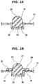
- a cross sectional shape of the gasket main body 21 is formed into, for example, a circular cross section as shown in Fig. 1B .
- Reference numeral 24 denotes a penetration portion (a space portion) which passes through the gasket main body 21 in its thickness direction.
- the gasket main body 21 is formed into a rectangular flat surface shape, is set its planar size to have an outer shape with about 400 mm (vertical) x about 300 mm (horizontal), and is set its thickness, that is, its wire diameter to be approximately 1 mm.
- the carrier sheet 31 is formed into a flat surface shape (a flat plate shape) by a predetermined resin film, and is formed into a rectangular flat surface which is one size larger than the gasket main body 21.
- the resin film employs, for example, a polypropylene film having a thickness of 0.2 mm, and is used by cutting the polypropylene film into a flat surface shape having the size mentioned above.
- General resin materials such as polyethylene and polystyrene can be used in addition to the polypropylene for the resin film.
- a thickness of the film is preferably set to be between 0.1 mm and 0.3 mm in correspondence to the wire diameter and the cross sectional shape of the gasket main body 21.
- a gasket retention portion 32 having a three-dimensional shape is provided at a position which is arranged on a part of the flat surface of the carrier sheet 31 and laps over the gasket main body 21 in a plane, the gasket retention portion 32 being formed into a shape which is deformed along an outer shape of the gasket main body 21 (an outer contour line in the cross sectional shape of the gasket main body 21). A part of the gasket main body 21 in a thickness direction is accommodated in the gasket retention portion 32. Since the cross sectional shape of the gasket main body 21 is formed into the circular cross section as mentioned above in the embodiment, a cross sectional shape of the gasket retention portion 32 is formed into a circular arc cross sectional shape (a semicircular shape) in correspondence thereto.
- a part in one side in the thickness direction of the gasket main body 21 is accommodated within a space portion 33 (a concave portion) 33 which is provided in a back surface side of the gasket retention portion 32 and is formed into a groove shape, on the basis of the provision of the gasket retention portion 32 having the circular arc cross sectional shape as mentioned above.
- the gasket main body 21 Since the gasket main body 21 is not bonded to the carrier sheet 31, the gasket main body 21 can be detached from the carrier sheet 31 when being stacked.
- the gasket main body 21 is formed in a state in which the carrier sheet 31 is inserted into a metal mold 41 which forms the gasket main body 21 as mentioned later, the gasket main body 21 is set to a state of being adhered to the carrier film 31 since the formed gasket main body 21 is provided with a adhesion.
- the adhesion has such a small adhesive force as to be detached by a chucking device. Therefore, in this case, the rubber only type gasket main body 21 is not bonded to the carrier film 31 which is made of the resin film, but is adhered in such a manner as to be capable of being peeled off.
- an air inflow port 34 is provided at a position which is a part of the carrier sheet 31 in a plane and laps over the gasket main body 21 in the plane, the air inflow port 34 being provided for flowing air into a portion between the carrier sheet 31 and the gasket main body 21 when the gasket main body 21 is detached from the carrier sheet 31.
- the air inflow port 34 is provided at a bottom surface position of the gasket retention portion 32.
- a plurality of air inflow ports 34 are provided along a longitudinal direction of the gasket retention portion 32.
- the air inflow ports 34 are provided at corresponding positions to corner portions (four positions) and center portions (two positions) of longitudinal side edges of the outer peripheral seal portion 22 in the gasket main body 21, and positions (eight positions) where the outer peripheral seal portion 22 and the inside seal portion 23 intersect, that is, totally fourteen positions.
- the gasket main body 21 since the rubber only type gasket main body 21 is retained by the carrier sheet 31 which is made of the resin film, the gasket main body 21 is hard to be twisted when the gasket 11 is carried, and the gasket 11 can be easily carried. Further, since the gasket main body 21 is not bonded to the carrier sheet 31, the gasket main body 21 can be easily detached from the carrier sheet 31 when being stacked. Therefore, it is possible to improve a handling workability of the gasket 11.
- the gasket retention portion 32 having the three-dimensional shape is provided in the carrier sheet 31 and a part of the gasket main body 21 is accommodated within the gasket retention portion 32, the gasket main body 21 is positioned on a plane in relation to the carrier sheet 31. Therefore, since the gasket main body 21 is not displaced in relation to the carrier sheet 31 when the gasket 11 is carried, the gasket main body 21 can be firmly retained by the carrier sheet 31.
- the gasket main body 21 can be easily detached (peeled) from the carrier sheet 31 by flowing (injecting) the air into the portion between the carrier sheet 31 and the gasket main body 21 from the air inflow port 34 when the gasket main body 21 is easily detached from the carrier sheet 31. Therefore, it is possible to provide a gasket product in which the gasket main body 21 can be easily detached from the carrier sheet while firmly retaining the gasket main body 21 by the carrier sheet 31.
- a seal lip 25 having a circular arc cross sectional shape (a semicircular shape) is integrally formed in an upper surface of the gasket main body 21 having the rectangular cross sectional shape.
- the cross sectional shape of the gasket retention portion 32 is also formed into a square cross section shape.
- the air inflow port 34 is provided in a planar bottom portion of the gasket retention portion 32.
- a seal lip 25 having a circular arc cross sectional shape (a semicircular shape) is integrally formed in an upper surface of the gasket main body 21 having the rectangular cross sectional shape, and a protruding portion 26 having a flat surface shape is integrally formed in a side surface portion of the gasket main body 21.
- the cross sectional shape of the gasket retention portion 32 is also formed into a rectangular cross sectional shape.
- the air inflow port 34 is provided at a position which laps over the protruding portion 26 on a plane next to the gasket retention portion 32 in the carrier sheet 31.
- the method of manufacturing the gasket according to the embodiment is provided for manufacturing the gasket 11 shown in Fig. 2A .
- a metal mold for injection molding the rubber only type gasket main body 21 is used for manufacturing.
- the carrier sheet 31 having the flat surface shape with a predetermined size is prepared.
- the metal mold 41 is clamped in a state in which the carrier sheet 31 is sandwiched in parting portions 44 of the metal mold 41.
- the metal mold 41 has a combination of an upper mold (one split mold) 42 and a lower mold (the other split mold) 43, and cavity portions 45 are correspondingly provided, for example, half by half in the parting portions 44 of both the molds 42 and 43. Since the carrier sheet 31 is initially formed into the flat surface shape in its whole surface, the carrier sheet 31 is set to a state of cutting across the cavity portion 45.
- a projection forming portion 46 is provided as a part of the cavity portion 45 in a bottom surface portion of the cavity portion 45 in the lower mold 43, the projection forming portion 46 being provided for forming in the carrier sheet 31 a hollow projection portion 35 which is later formed into the air inflow port 34.
- the gasket main body 21 is formed by filling a molding material for forming the gasket main body 21 in the cavity portion 45 and heating the molding material.
- the carrier sheet 31 is pressed to an inner surface of the cavity portion 45 in its part (a portion within the cavity) of the plane by a forming material filling pressure, and is deformed (plastically deformed) into a shape which is along the inner surface of the cavity portion 45.
- the gasket retention portion 32 and the hollow projection portion 35 are formed.
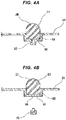
- the mold is opened after the formation of the gasket main body 21, and the gasket main body 21 and the carrier sheet 31 are simultaneously taken out of the metal mold 41 as shown in Fig. 4A .
- the taken-out gasket main body 21 and carrier sheet 31 are formed into a combination state in which the gasket main body 21 is retained by the carrier sheet 31.
- the hollow projection portion 35 is removed (cut) together with the rubber filled in the inner portion thereof from the carrier sheet 31, and the air inflow port 34 is formed accordingly in the carrier sheet 31.
- the manufacturing of the gasket 11 is finished by the above steps.
- the gasket main body 21 and the carrier sheet 31 are carried and stored as a product in a state of being combined with each other.
- the torsion is hard to be generated in the gasket main body 21 which is retained by the carrier sheet 31. Therefore, the handling workability is improved in comparison with the case that the gasket main body 21 is handled as a single part.
- the air inflow port 34 is provided in the carrier sheet 31 as mentioned above, the gasket main body 21 can be easily detached (peeled) from the carrier sheet 31 by flowing (injecting) the air into the portion between the carrier sheet 31 and the gasket main body 21 from the air inflow port 34 when the gasket main body 21 is detached from the carrier sheet 31.
- the air inflow port 34 is formed by forming the hollow projection portion 35 at the position which laps over the protruding portion 26 on the plane beside the gasket retention portion 32 in the carrier sheet 31 as shown in Fig. 5A in reference to the forming position of the air inflow port 34, and removing (cutting) the projection portion 35 together with the rubber filled into the inner portion thereof in the later step as shown in Fig. 5B .
- the method of forming the air inflow port 34 may be structured, as shown in Figs. 6A and 6B , such that the air inflow port 34 is provided previously at a predetermined position of the carrier sheet 31 as shown in Figs. 6A and 6B .
- the gasket main body 21 when the gasket main body 21 is assembled in a fuel battery stack, the gasket main body 21 is gripped and lifted up by a chucking device in a state in which the carrier sheet 31 is adsorbed and fixed to a base side by a vacuuming device, and is moved to a predetermined position.
- the gasket main body 21 in which the torsion is not generated is easily gripped by the chucking device, and it is possible to smoothly go on the work.
Landscapes
- Engineering & Computer Science (AREA)
- General Engineering & Computer Science (AREA)
- Mechanical Engineering (AREA)
- Manufacturing & Machinery (AREA)
- Sustainable Energy (AREA)
- Sustainable Development (AREA)
- Life Sciences & Earth Sciences (AREA)
- Chemical & Material Sciences (AREA)
- Chemical Kinetics & Catalysis (AREA)
- Electrochemistry (AREA)
- General Chemical & Material Sciences (AREA)
- Gasket Seals (AREA)
- Fuel Cell (AREA)
Claims (5)
- Dichtung, mit:einem Dichtungshauptkörper (21), der nur aus Gummi besteht;einer Trägerplatte (31), welche aus einem Harzfilm gemacht ist, die den Dichtungshauptkörper (21) in einem nicht verbundenen Zustand sichert; gekennzeichnet durcheine Lufteinlassöffnung (34), um Luft in einen Abschnitt zwischen der Trägerplatte (31) und dem Dichtungshauptkörper (21) strömen zu lassen, wenn der Dichtungshauptkörper (21) von der Trägerplatte (31) getrennt ist, wobei die Lufteinlassöffnung (34) in der Trägerplatte (31) vorgesehen ist.
- Dichtung nach Anspruch 1, wobei die Trägerplatte (31) ferner einen Dichtungssicherungsabschnitt (32) hat, der eine dreidimensionale Form hat, welche entlang einer Außenform des Dichtungshauptkörpers (21) verformt ist,
wobei der Dichtungssicherungsabschnitt (32) an einer Position angeordnet ist, welche den Dichtungshauptkörper (21) in einer Ebene in der Trägerplatte (31) überlappt,
wobei der Dichtungshauptkörper (21) in dem Dichtungssicherungsabschnitt (32) in einer Dickenrichtung teilweise aufgenommen ist und
wobei die Lufteinlassöffnung (34) an einer Bodenflächenposition (33) des Dichtungssicherungsabschnitts (32) angeordnet ist. - Dichtung nach Anspruch 1, wobei die Trägerplatte (31) ferner einen Dichtungssicherungsabschnitt (32) hat, der eine dreidimensionale Form hat, welche entlang einer Außenform des Dichtungshauptkörpers (21) verformt ist,
wobei der Dichtungssicherungsabschnitt (32) an einer Position angeordnet ist, welche den Dichtungshauptkörper (21) in einer Ebene in der Trägerplatte (31) überlappt,
wobei der Dichtungshauptkörper (21) in dem Dichtungssicherungsabschnitt (32) in einer Dickenrichtung teilweise aufgenommen ist,
wobei ein Vorsprungsabschnitt (26) auf einer Seitenoberfläche des Dichtungshauptkörpers (21) angeordnet ist und
wobei die Lufteinlassöffnung (34) an einer Position angeordnet ist, welche den Vorsprungsabschnitt (26) in einer Ebene in der Trägerplatte (31) überlappt. - Dichtung nach einem der Ansprüche 1 bis 3, wobei der Dichtungshauptkörper (21) als eine Dichtung für eine Brennstoffzelle verwendet wird, welche in einem Brennstoffzellenstapel eingebaut ist.
- Herstellungsverfahren der Dichtung nach einem der Ansprüche 1 bis 4, mit:einem Schritt Formaufspannen einer Metallform (41) in einem Zustand, in welchem eine Trägerplatte (31) mit einer flachen Oberflächenform in Teilungsabschnitten der Metallform (41) zwischengeordnet ist, die einen Dichtungshauptkörper ausbilden;einem Schritt Ausbilden des Dichtungshauptkörpers (21) durch die Metallform (41) und Ausbilden eines Dichtungssicherungsabschnitts (32) mit einer dreidimensionalen Form, indem ein Abschnitt in einer Ebene der Trägerplatte (31) entlang einer Innenoberfläche einer Metallformkavität (45) mit einem Formgebungsmaterial verformt wird, das zu diesem Zeitpunkt Druck aufbringt;einem Schritt Öffnen der Form (41) nach dem Ausbilden des Dichtungshauptkörpers (21) und danach einem gleichzeitigen Herausnehmen des Dichtungshauptkörpers (21) und der Trägerplatte (31) aus der Metallform (41); gekennzeichnet durcheinen Schritt Ausbilden der Lufteinlassöffnung (34), indem von den Schritten in dem Schritt Ausbilden des Dichtungshauptkörpers (21) mit der Metallform (41) an einem Abschnitt in einer Ebene der Trägerplatte (31) ein Hohlvorsprungsabschnitt (35) ausgebildet wird und der Vorsprungsabschnitt (35) in dem späteren Schritt abgeschnitten wird.
Applications Claiming Priority (2)
| Application Number | Priority Date | Filing Date | Title |
|---|---|---|---|
| JP2015113596A JP6495106B2 (ja) | 2015-06-04 | 2015-06-04 | ガスケット及びその製造方法 |
| PCT/JP2016/064078 WO2016194573A1 (ja) | 2015-06-04 | 2016-05-12 | ガスケット及びその製造方法 |
Publications (3)
| Publication Number | Publication Date |
|---|---|
| EP3306147A1 EP3306147A1 (de) | 2018-04-11 |
| EP3306147A4 EP3306147A4 (de) | 2018-07-11 |
| EP3306147B1 true EP3306147B1 (de) | 2019-07-10 |
Family
ID=57442371
Family Applications (1)
| Application Number | Title | Priority Date | Filing Date |
|---|---|---|---|
| EP16803010.4A Active EP3306147B1 (de) | 2015-06-04 | 2016-05-12 | Dichtung und verfahren zur herstellung davon |
Country Status (7)
| Country | Link |
|---|---|
| US (1) | US10465798B2 (de) |
| EP (1) | EP3306147B1 (de) |
| JP (1) | JP6495106B2 (de) |
| KR (1) | KR102521010B1 (de) |
| CN (1) | CN107407414B (de) |
| CA (1) | CA2987711C (de) |
| WO (1) | WO2016194573A1 (de) |
Families Citing this family (13)
| Publication number | Priority date | Publication date | Assignee | Title |
|---|---|---|---|---|
| US10513066B2 (en) * | 2015-04-24 | 2019-12-24 | Nok Corporation | Gasket molded product and method of manufacturing the same |
| CA2987812C (en) * | 2015-06-04 | 2023-08-22 | Nok Corporation | Gasket and method for producing same |
| JP6795349B2 (ja) * | 2015-11-10 | 2020-12-02 | Nok株式会社 | キャリアフィルム付きガスケットの取り扱い方法 |
| JP6673678B2 (ja) * | 2015-12-03 | 2020-03-25 | Nok株式会社 | キャリアフィルム付きガスケット及びその製造方法 |
| US10960585B2 (en) | 2015-12-24 | 2021-03-30 | Nok Corporation | Gasket, method for producing same, and method for handling same |
| JP6325041B2 (ja) * | 2016-08-31 | 2018-05-16 | 三菱重工サーマルシステムズ株式会社 | スクロール流体機械およびチップシール |
| CN109642672B (zh) | 2016-10-27 | 2021-03-23 | Nok株式会社 | 密封垫及其制造方法 |
| CN108461776A (zh) * | 2017-12-29 | 2018-08-28 | 上海神力科技有限公司 | 一种燃料电池电堆用密封垫及其制备方法 |
| WO2019188796A1 (ja) * | 2018-03-27 | 2019-10-03 | 富士フイルム株式会社 | 凹状台座パターンを有するモールドの作製方法及びパターンシートの製造方法 |
| US11973246B2 (en) | 2019-09-18 | 2024-04-30 | Nok Corporation | Method for manufacturing fuel battery cell separator gasket |
| EP4101618B1 (de) * | 2020-02-06 | 2025-10-29 | NOK Corporation | Dichtung mit integriertem separator und herstellungsverfahren dafür |
| EP4483398A1 (de) * | 2022-02-25 | 2025-01-01 | Applied Materials, Inc. | O-ring-montageschablone und verfahren |
| US20240167568A1 (en) * | 2022-11-22 | 2024-05-23 | Parker-Hannifin Corporation | Friction fit seal with flange and flange sealing bead |
Family Cites Families (10)
| Publication number | Priority date | Publication date | Assignee | Title |
|---|---|---|---|---|
| JPS54159552A (en) * | 1978-06-06 | 1979-12-17 | Toyo Cloth Co | Gasket and its manufacturing method |
| JPS5933294B2 (ja) * | 1979-04-30 | 1984-08-15 | 豊田合成株式会社 | 成形金型 |
| US4748092A (en) | 1987-01-02 | 1988-05-31 | Continental Can Company, Inc. | Frame for a cell construction |
| EP0679501A1 (de) * | 1994-03-14 | 1995-11-02 | YMOS AKTIENGESELLSCHAFT Industrieprodukte | Verbundmaterial mit schaumfähigem Kern |
| JP4530122B2 (ja) * | 2001-03-09 | 2010-08-25 | Nok株式会社 | ガスケット |
| JP4706818B2 (ja) * | 2003-06-16 | 2011-06-22 | Nok株式会社 | 燃料電池用ガスケット |
| CN100583525C (zh) | 2003-07-08 | 2010-01-20 | Nok株式会社 | 燃料电池用隔板 |
| JP4678123B2 (ja) | 2003-09-02 | 2011-04-27 | Nok株式会社 | ガスケット |
| CN2879433Y (zh) | 2006-02-15 | 2007-03-14 | 南京博能燃料电池有限责任公司 | 隧道型燃料电池双极板 |
| KR101449124B1 (ko) | 2012-09-17 | 2014-10-08 | 현대자동차주식회사 | 수소연료전지용 사출성형 일체화 불소계 가스켓 |
-
2015
- 2015-06-04 JP JP2015113596A patent/JP6495106B2/ja active Active
-
2016
- 2016-05-12 US US15/578,619 patent/US10465798B2/en active Active
- 2016-05-12 EP EP16803010.4A patent/EP3306147B1/de active Active
- 2016-05-12 CA CA2987711A patent/CA2987711C/en active Active
- 2016-05-12 WO PCT/JP2016/064078 patent/WO2016194573A1/ja not_active Ceased
- 2016-05-12 CN CN201680017486.7A patent/CN107407414B/zh active Active
- 2016-05-12 KR KR1020177034868A patent/KR102521010B1/ko active Active
Non-Patent Citations (1)
| Title |
|---|
| None * |
Also Published As
| Publication number | Publication date |
|---|---|
| CA2987711C (en) | 2023-03-28 |
| EP3306147A4 (de) | 2018-07-11 |
| CN107407414B (zh) | 2018-10-26 |
| CA2987711A1 (en) | 2016-12-08 |
| WO2016194573A1 (ja) | 2016-12-08 |
| JP2016223616A (ja) | 2016-12-28 |
| KR20180015149A (ko) | 2018-02-12 |
| KR102521010B1 (ko) | 2023-04-11 |
| US20180163870A1 (en) | 2018-06-14 |
| EP3306147A1 (de) | 2018-04-11 |
| US10465798B2 (en) | 2019-11-05 |
| CN107407414A (zh) | 2017-11-28 |
| JP6495106B2 (ja) | 2019-04-03 |
Similar Documents
| Publication | Publication Date | Title |
|---|---|---|
| US10465798B2 (en) | Gasket and method of manufacturing the same | |
| EP3282151B1 (de) | Dichtung und herstellungsverfahren dafür | |
| EP3306148B1 (de) | Dichtung und verfahren zur herstellung davon | |
| EP3287673B1 (de) | Dichtungsformteil und herstellungsverfahren dafür | |
| KR102645670B1 (ko) | 개스킷 및 그 제조방법 및 취급방법 | |
| EP3385575B1 (de) | Dichtung und herstellungsverfahren dafür | |
| JP2017106478A (ja) | ガスケット並びにその製造方法及び取り扱い方法 |
Legal Events
| Date | Code | Title | Description |
|---|---|---|---|
| STAA | Information on the status of an ep patent application or granted ep patent |
Free format text: STATUS: THE INTERNATIONAL PUBLICATION HAS BEEN MADE |
|
| PUAI | Public reference made under article 153(3) epc to a published international application that has entered the european phase |
Free format text: ORIGINAL CODE: 0009012 |
|
| STAA | Information on the status of an ep patent application or granted ep patent |
Free format text: STATUS: REQUEST FOR EXAMINATION WAS MADE |
|
| 17P | Request for examination filed |
Effective date: 20171211 |
|
| AK | Designated contracting states |
Kind code of ref document: A1 Designated state(s): AL AT BE BG CH CY CZ DE DK EE ES FI FR GB GR HR HU IE IS IT LI LT LU LV MC MK MT NL NO PL PT RO RS SE SI SK SM TR |
|
| AX | Request for extension of the european patent |
Extension state: BA ME |
|
| A4 | Supplementary search report drawn up and despatched |
Effective date: 20180611 |
|
| RIC1 | Information provided on ipc code assigned before grant |
Ipc: H01M 8/0271 20160101ALI20180605BHEP Ipc: B29C 45/14 20060101ALI20180605BHEP Ipc: F16J 15/10 20060101ALI20180605BHEP Ipc: F16J 15/00 20060101AFI20180605BHEP |
|
| DAV | Request for validation of the european patent (deleted) | ||
| DAX | Request for extension of the european patent (deleted) | ||
| REG | Reference to a national code |
Ref country code: DE Ref legal event code: R079 Ref document number: 602016016821 Country of ref document: DE Free format text: PREVIOUS MAIN CLASS: F16J0015000000 Ipc: B29L0031260000 |
|
| GRAP | Despatch of communication of intention to grant a patent |
Free format text: ORIGINAL CODE: EPIDOSNIGR1 |
|
| STAA | Information on the status of an ep patent application or granted ep patent |
Free format text: STATUS: GRANT OF PATENT IS INTENDED |
|
| RIC1 | Information provided on ipc code assigned before grant |
Ipc: H01M 8/0271 20160101ALI20181126BHEP Ipc: B29C 44/58 20060101ALI20181126BHEP Ipc: B29C 45/26 20060101ALI20181126BHEP Ipc: F16J 15/10 20060101ALI20181126BHEP Ipc: B29L 31/26 20060101AFI20181126BHEP Ipc: B29C 45/14 20060101ALI20181126BHEP |
|
| INTG | Intention to grant announced |
Effective date: 20181220 |
|
| GRAS | Grant fee paid |
Free format text: ORIGINAL CODE: EPIDOSNIGR3 |
|
| GRAA | (expected) grant |
Free format text: ORIGINAL CODE: 0009210 |
|
| STAA | Information on the status of an ep patent application or granted ep patent |
Free format text: STATUS: THE PATENT HAS BEEN GRANTED |
|
| AK | Designated contracting states |
Kind code of ref document: B1 Designated state(s): AL AT BE BG CH CY CZ DE DK EE ES FI FR GB GR HR HU IE IS IT LI LT LU LV MC MK MT NL NO PL PT RO RS SE SI SK SM TR |
|
| REG | Reference to a national code |
Ref country code: GB Ref legal event code: FG4D |
|
| REG | Reference to a national code |
Ref country code: CH Ref legal event code: EP Ref country code: AT Ref legal event code: REF Ref document number: 1153075 Country of ref document: AT Kind code of ref document: T Effective date: 20190715 |
|
| REG | Reference to a national code |
Ref country code: DE Ref legal event code: R096 Ref document number: 602016016821 Country of ref document: DE |
|
| REG | Reference to a national code |
Ref country code: IE Ref legal event code: FG4D |
|
| REG | Reference to a national code |
Ref country code: NL Ref legal event code: MP Effective date: 20190710 |
|
| REG | Reference to a national code |
Ref country code: LT Ref legal event code: MG4D |
|
| REG | Reference to a national code |
Ref country code: AT Ref legal event code: MK05 Ref document number: 1153075 Country of ref document: AT Kind code of ref document: T Effective date: 20190710 |
|
| PG25 | Lapsed in a contracting state [announced via postgrant information from national office to epo] |
Ref country code: FI Free format text: LAPSE BECAUSE OF FAILURE TO SUBMIT A TRANSLATION OF THE DESCRIPTION OR TO PAY THE FEE WITHIN THE PRESCRIBED TIME-LIMIT Effective date: 20190710 Ref country code: SE Free format text: LAPSE BECAUSE OF FAILURE TO SUBMIT A TRANSLATION OF THE DESCRIPTION OR TO PAY THE FEE WITHIN THE PRESCRIBED TIME-LIMIT Effective date: 20190710 Ref country code: LT Free format text: LAPSE BECAUSE OF FAILURE TO SUBMIT A TRANSLATION OF THE DESCRIPTION OR TO PAY THE FEE WITHIN THE PRESCRIBED TIME-LIMIT Effective date: 20190710 Ref country code: HR Free format text: LAPSE BECAUSE OF FAILURE TO SUBMIT A TRANSLATION OF THE DESCRIPTION OR TO PAY THE FEE WITHIN THE PRESCRIBED TIME-LIMIT Effective date: 20190710 Ref country code: NO Free format text: LAPSE BECAUSE OF FAILURE TO SUBMIT A TRANSLATION OF THE DESCRIPTION OR TO PAY THE FEE WITHIN THE PRESCRIBED TIME-LIMIT Effective date: 20191010 Ref country code: BG Free format text: LAPSE BECAUSE OF FAILURE TO SUBMIT A TRANSLATION OF THE DESCRIPTION OR TO PAY THE FEE WITHIN THE PRESCRIBED TIME-LIMIT Effective date: 20191010 Ref country code: AT Free format text: LAPSE BECAUSE OF FAILURE TO SUBMIT A TRANSLATION OF THE DESCRIPTION OR TO PAY THE FEE WITHIN THE PRESCRIBED TIME-LIMIT Effective date: 20190710 Ref country code: NL Free format text: LAPSE BECAUSE OF FAILURE TO SUBMIT A TRANSLATION OF THE DESCRIPTION OR TO PAY THE FEE WITHIN THE PRESCRIBED TIME-LIMIT Effective date: 20190710 Ref country code: PT Free format text: LAPSE BECAUSE OF FAILURE TO SUBMIT A TRANSLATION OF THE DESCRIPTION OR TO PAY THE FEE WITHIN THE PRESCRIBED TIME-LIMIT Effective date: 20191111 |
|
| PG25 | Lapsed in a contracting state [announced via postgrant information from national office to epo] |
Ref country code: AL Free format text: LAPSE BECAUSE OF FAILURE TO SUBMIT A TRANSLATION OF THE DESCRIPTION OR TO PAY THE FEE WITHIN THE PRESCRIBED TIME-LIMIT Effective date: 20190710 Ref country code: LV Free format text: LAPSE BECAUSE OF FAILURE TO SUBMIT A TRANSLATION OF THE DESCRIPTION OR TO PAY THE FEE WITHIN THE PRESCRIBED TIME-LIMIT Effective date: 20190710 Ref country code: ES Free format text: LAPSE BECAUSE OF FAILURE TO SUBMIT A TRANSLATION OF THE DESCRIPTION OR TO PAY THE FEE WITHIN THE PRESCRIBED TIME-LIMIT Effective date: 20190710 Ref country code: RS Free format text: LAPSE BECAUSE OF FAILURE TO SUBMIT A TRANSLATION OF THE DESCRIPTION OR TO PAY THE FEE WITHIN THE PRESCRIBED TIME-LIMIT Effective date: 20190710 Ref country code: GR Free format text: LAPSE BECAUSE OF FAILURE TO SUBMIT A TRANSLATION OF THE DESCRIPTION OR TO PAY THE FEE WITHIN THE PRESCRIBED TIME-LIMIT Effective date: 20191011 Ref country code: IS Free format text: LAPSE BECAUSE OF FAILURE TO SUBMIT A TRANSLATION OF THE DESCRIPTION OR TO PAY THE FEE WITHIN THE PRESCRIBED TIME-LIMIT Effective date: 20191110 |
|
| PG25 | Lapsed in a contracting state [announced via postgrant information from national office to epo] |
Ref country code: TR Free format text: LAPSE BECAUSE OF FAILURE TO SUBMIT A TRANSLATION OF THE DESCRIPTION OR TO PAY THE FEE WITHIN THE PRESCRIBED TIME-LIMIT Effective date: 20190710 |
|
| PG25 | Lapsed in a contracting state [announced via postgrant information from national office to epo] |
Ref country code: RO Free format text: LAPSE BECAUSE OF FAILURE TO SUBMIT A TRANSLATION OF THE DESCRIPTION OR TO PAY THE FEE WITHIN THE PRESCRIBED TIME-LIMIT Effective date: 20190710 Ref country code: IT Free format text: LAPSE BECAUSE OF FAILURE TO SUBMIT A TRANSLATION OF THE DESCRIPTION OR TO PAY THE FEE WITHIN THE PRESCRIBED TIME-LIMIT Effective date: 20190710 Ref country code: DK Free format text: LAPSE BECAUSE OF FAILURE TO SUBMIT A TRANSLATION OF THE DESCRIPTION OR TO PAY THE FEE WITHIN THE PRESCRIBED TIME-LIMIT Effective date: 20190710 Ref country code: PL Free format text: LAPSE BECAUSE OF FAILURE TO SUBMIT A TRANSLATION OF THE DESCRIPTION OR TO PAY THE FEE WITHIN THE PRESCRIBED TIME-LIMIT Effective date: 20190710 Ref country code: EE Free format text: LAPSE BECAUSE OF FAILURE TO SUBMIT A TRANSLATION OF THE DESCRIPTION OR TO PAY THE FEE WITHIN THE PRESCRIBED TIME-LIMIT Effective date: 20190710 |
|
| PG25 | Lapsed in a contracting state [announced via postgrant information from national office to epo] |
Ref country code: CZ Free format text: LAPSE BECAUSE OF FAILURE TO SUBMIT A TRANSLATION OF THE DESCRIPTION OR TO PAY THE FEE WITHIN THE PRESCRIBED TIME-LIMIT Effective date: 20190710 Ref country code: SM Free format text: LAPSE BECAUSE OF FAILURE TO SUBMIT A TRANSLATION OF THE DESCRIPTION OR TO PAY THE FEE WITHIN THE PRESCRIBED TIME-LIMIT Effective date: 20190710 Ref country code: IS Free format text: LAPSE BECAUSE OF FAILURE TO SUBMIT A TRANSLATION OF THE DESCRIPTION OR TO PAY THE FEE WITHIN THE PRESCRIBED TIME-LIMIT Effective date: 20200224 Ref country code: SK Free format text: LAPSE BECAUSE OF FAILURE TO SUBMIT A TRANSLATION OF THE DESCRIPTION OR TO PAY THE FEE WITHIN THE PRESCRIBED TIME-LIMIT Effective date: 20190710 |
|
| REG | Reference to a national code |
Ref country code: DE Ref legal event code: R097 Ref document number: 602016016821 Country of ref document: DE |
|
| PLBE | No opposition filed within time limit |
Free format text: ORIGINAL CODE: 0009261 |
|
| STAA | Information on the status of an ep patent application or granted ep patent |
Free format text: STATUS: NO OPPOSITION FILED WITHIN TIME LIMIT |
|
| PG2D | Information on lapse in contracting state deleted |
Ref country code: IS |
|
| 26N | No opposition filed |
Effective date: 20200603 |
|
| PG25 | Lapsed in a contracting state [announced via postgrant information from national office to epo] |
Ref country code: SI Free format text: LAPSE BECAUSE OF FAILURE TO SUBMIT A TRANSLATION OF THE DESCRIPTION OR TO PAY THE FEE WITHIN THE PRESCRIBED TIME-LIMIT Effective date: 20190710 |
|
| PG25 | Lapsed in a contracting state [announced via postgrant information from national office to epo] |
Ref country code: LI Free format text: LAPSE BECAUSE OF NON-PAYMENT OF DUE FEES Effective date: 20200531 Ref country code: MC Free format text: LAPSE BECAUSE OF FAILURE TO SUBMIT A TRANSLATION OF THE DESCRIPTION OR TO PAY THE FEE WITHIN THE PRESCRIBED TIME-LIMIT Effective date: 20190710 Ref country code: CH Free format text: LAPSE BECAUSE OF NON-PAYMENT OF DUE FEES Effective date: 20200531 |
|
| REG | Reference to a national code |
Ref country code: BE Ref legal event code: MM Effective date: 20200531 |
|
| PG25 | Lapsed in a contracting state [announced via postgrant information from national office to epo] |
Ref country code: LU Free format text: LAPSE BECAUSE OF NON-PAYMENT OF DUE FEES Effective date: 20200512 |
|
| PG25 | Lapsed in a contracting state [announced via postgrant information from national office to epo] |
Ref country code: IE Free format text: LAPSE BECAUSE OF NON-PAYMENT OF DUE FEES Effective date: 20200512 |
|
| PG25 | Lapsed in a contracting state [announced via postgrant information from national office to epo] |
Ref country code: BE Free format text: LAPSE BECAUSE OF NON-PAYMENT OF DUE FEES Effective date: 20200531 |
|
| PG25 | Lapsed in a contracting state [announced via postgrant information from national office to epo] |
Ref country code: MT Free format text: LAPSE BECAUSE OF FAILURE TO SUBMIT A TRANSLATION OF THE DESCRIPTION OR TO PAY THE FEE WITHIN THE PRESCRIBED TIME-LIMIT Effective date: 20190710 Ref country code: CY Free format text: LAPSE BECAUSE OF FAILURE TO SUBMIT A TRANSLATION OF THE DESCRIPTION OR TO PAY THE FEE WITHIN THE PRESCRIBED TIME-LIMIT Effective date: 20190710 |
|
| PG25 | Lapsed in a contracting state [announced via postgrant information from national office to epo] |
Ref country code: MK Free format text: LAPSE BECAUSE OF FAILURE TO SUBMIT A TRANSLATION OF THE DESCRIPTION OR TO PAY THE FEE WITHIN THE PRESCRIBED TIME-LIMIT Effective date: 20190710 |
|
| PGFP | Annual fee paid to national office [announced via postgrant information from national office to epo] |
Ref country code: FR Payment date: 20240328 Year of fee payment: 9 |
|
| PGFP | Annual fee paid to national office [announced via postgrant information from national office to epo] |
Ref country code: GB Payment date: 20240402 Year of fee payment: 9 |
|
| PGFP | Annual fee paid to national office [announced via postgrant information from national office to epo] |
Ref country code: DE Payment date: 20250402 Year of fee payment: 10 |
|
| GBPC | Gb: european patent ceased through non-payment of renewal fee |
Effective date: 20250512 |
|
| PG25 | Lapsed in a contracting state [announced via postgrant information from national office to epo] |
Ref country code: GB Free format text: LAPSE BECAUSE OF NON-PAYMENT OF DUE FEES Effective date: 20250512 |
|
| PG25 | Lapsed in a contracting state [announced via postgrant information from national office to epo] |
Ref country code: FR Free format text: LAPSE BECAUSE OF NON-PAYMENT OF DUE FEES Effective date: 20250531 |