EP3305533B1 - Procédé de traitement d'une bande dans un appareil - Google Patents
Procédé de traitement d'une bande dans un appareil Download PDFInfo
- Publication number
- EP3305533B1 EP3305533B1 EP17192344.4A EP17192344A EP3305533B1 EP 3305533 B1 EP3305533 B1 EP 3305533B1 EP 17192344 A EP17192344 A EP 17192344A EP 3305533 B1 EP3305533 B1 EP 3305533B1
- Authority
- EP
- European Patent Office
- Prior art keywords
- guard
- web
- support platen
- control unit
- printing station
- Prior art date
- Legal status (The legal status is an assumption and is not a legal conclusion. Google has not performed a legal analysis and makes no representation as to the accuracy of the status listed.)
- Active
Links
- 238000000034 method Methods 0.000 title claims description 31
- 238000007639 printing Methods 0.000 claims description 41
- 239000003550 marker Substances 0.000 claims description 30
- 238000001514 detection method Methods 0.000 claims description 9
- 125000006850 spacer group Chemical group 0.000 claims description 7
- 230000032258 transport Effects 0.000 description 50
- 239000000463 material Substances 0.000 description 21
- 230000005855 radiation Effects 0.000 description 6
- 238000007641 inkjet printing Methods 0.000 description 5
- 239000012530 fluid Substances 0.000 description 4
- 239000003086 colorant Substances 0.000 description 3
- 238000001723 curing Methods 0.000 description 3
- 230000001419 dependent effect Effects 0.000 description 3
- 239000000123 paper Substances 0.000 description 3
- 238000003847 radiation curing Methods 0.000 description 3
- 238000010586 diagram Methods 0.000 description 2
- 230000004044 response Effects 0.000 description 2
- 238000003860 storage Methods 0.000 description 2
- 238000010146 3D printing Methods 0.000 description 1
- 230000003213 activating effect Effects 0.000 description 1
- 238000004026 adhesive bonding Methods 0.000 description 1
- 238000013459 approach Methods 0.000 description 1
- 238000003491 array Methods 0.000 description 1
- 230000006399 behavior Effects 0.000 description 1
- -1 canvas Substances 0.000 description 1
- 239000011248 coating agent Substances 0.000 description 1
- 238000000576 coating method Methods 0.000 description 1
- 238000004891 communication Methods 0.000 description 1
- 238000001035 drying Methods 0.000 description 1
- 230000005389 magnetism Effects 0.000 description 1
- 238000004519 manufacturing process Methods 0.000 description 1
- 230000003287 optical effect Effects 0.000 description 1
- 239000004753 textile Substances 0.000 description 1
- 238000009736 wetting Methods 0.000 description 1
Images


Classifications
-
- B—PERFORMING OPERATIONS; TRANSPORTING
- B41—PRINTING; LINING MACHINES; TYPEWRITERS; STAMPS
- B41J—TYPEWRITERS; SELECTIVE PRINTING MECHANISMS, i.e. MECHANISMS PRINTING OTHERWISE THAN FROM A FORME; CORRECTION OF TYPOGRAPHICAL ERRORS
- B41J11/00—Devices or arrangements of selective printing mechanisms, e.g. ink-jet printers or thermal printers, for supporting or handling copy material in sheet or web form
- B41J11/0025—Handling copy materials differing in width
- B41J11/003—Paper-size detection, i.e. automatic detection of the length and/or width of copy material
-
- B—PERFORMING OPERATIONS; TRANSPORTING
- B41—PRINTING; LINING MACHINES; TYPEWRITERS; STAMPS
- B41J—TYPEWRITERS; SELECTIVE PRINTING MECHANISMS, i.e. MECHANISMS PRINTING OTHERWISE THAN FROM A FORME; CORRECTION OF TYPOGRAPHICAL ERRORS
- B41J11/00—Devices or arrangements of selective printing mechanisms, e.g. ink-jet printers or thermal printers, for supporting or handling copy material in sheet or web form
- B41J11/0045—Guides for printing material
- B41J11/005—Guides in the printing zone, e.g. guides for preventing contact of conveyed sheets with printhead
-
- B—PERFORMING OPERATIONS; TRANSPORTING
- B41—PRINTING; LINING MACHINES; TYPEWRITERS; STAMPS
- B41J—TYPEWRITERS; SELECTIVE PRINTING MECHANISMS, i.e. MECHANISMS PRINTING OTHERWISE THAN FROM A FORME; CORRECTION OF TYPOGRAPHICAL ERRORS
- B41J11/00—Devices or arrangements of selective printing mechanisms, e.g. ink-jet printers or thermal printers, for supporting or handling copy material in sheet or web form
- B41J11/0045—Guides for printing material
- B41J11/0055—Lateral guides, e.g. guides for preventing skewed conveyance of printing material
-
- B—PERFORMING OPERATIONS; TRANSPORTING
- B41—PRINTING; LINING MACHINES; TYPEWRITERS; STAMPS
- B41J—TYPEWRITERS; SELECTIVE PRINTING MECHANISMS, i.e. MECHANISMS PRINTING OTHERWISE THAN FROM A FORME; CORRECTION OF TYPOGRAPHICAL ERRORS
- B41J11/00—Devices or arrangements of selective printing mechanisms, e.g. ink-jet printers or thermal printers, for supporting or handling copy material in sheet or web form
- B41J11/007—Conveyor belts or like feeding devices
-
- B—PERFORMING OPERATIONS; TRANSPORTING
- B41—PRINTING; LINING MACHINES; TYPEWRITERS; STAMPS
- B41J—TYPEWRITERS; SELECTIVE PRINTING MECHANISMS, i.e. MECHANISMS PRINTING OTHERWISE THAN FROM A FORME; CORRECTION OF TYPOGRAPHICAL ERRORS
- B41J11/00—Devices or arrangements of selective printing mechanisms, e.g. ink-jet printers or thermal printers, for supporting or handling copy material in sheet or web form
- B41J11/02—Platens
- B41J11/04—Roller platens
-
- B—PERFORMING OPERATIONS; TRANSPORTING
- B41—PRINTING; LINING MACHINES; TYPEWRITERS; STAMPS
- B41J—TYPEWRITERS; SELECTIVE PRINTING MECHANISMS, i.e. MECHANISMS PRINTING OTHERWISE THAN FROM A FORME; CORRECTION OF TYPOGRAPHICAL ERRORS
- B41J15/00—Devices or arrangements of selective printing mechanisms, e.g. ink-jet printers or thermal printers, specially adapted for supporting or handling copy material in continuous form, e.g. webs
- B41J15/04—Supporting, feeding, or guiding devices; Mountings for web rolls or spindles
-
- B—PERFORMING OPERATIONS; TRANSPORTING
- B41—PRINTING; LINING MACHINES; TYPEWRITERS; STAMPS
- B41J—TYPEWRITERS; SELECTIVE PRINTING MECHANISMS, i.e. MECHANISMS PRINTING OTHERWISE THAN FROM A FORME; CORRECTION OF TYPOGRAPHICAL ERRORS
- B41J25/00—Actions or mechanisms not otherwise provided for
- B41J25/304—Bodily-movable mechanisms for print heads or carriages movable towards or from paper surface
- B41J25/308—Bodily-movable mechanisms for print heads or carriages movable towards or from paper surface with print gap adjustment mechanisms
-
- B—PERFORMING OPERATIONS; TRANSPORTING
- B65—CONVEYING; PACKING; STORING; HANDLING THIN OR FILAMENTARY MATERIAL
- B65H—HANDLING THIN OR FILAMENTARY MATERIAL, e.g. SHEETS, WEBS, CABLES
- B65H2404/00—Parts for transporting or guiding the handled material
- B65H2404/70—Other elements in edge contact with handled material, e.g. registering, orientating, guiding devices
- B65H2404/72—Stops, gauge pins, e.g. stationary
Definitions
- the present invention relates to a method for printing a web in an apparatus.
- the present invention further relates to a printing apparatus comprising a printing station for processing a web.
- the present invention further relates to a first guard for guarding a side edge of a web.
- a known printing apparatus comprises a print station for processing a web by printing an image on the web, a transport device, such as a transport nip, for transporting the web through a transport path along the print station and a support platen facing the print station for supporting the web, when the web is processed by the print station.
- a pair of side guards is connected to the support platen for guiding the web along the transport path while guarding a respective side edge of the web, i.e. limiting a deformation or protrusion of the side edge of the web away from the support platen.
- the print station comprises a print assembly movably arranged with the support platen in a direction across the transport path to process the web.
- the pair of side guards is positioned on the support platen to prevent each side edge of the web from touching the print station, when the web is transported along the print station, as this can damage or pollute the web or the print station.
- Each side guard has a fixed shape and is connected to the support platen to fence and accommodate the side edge of the web between a guard portion of the side guard and the support platen, when guiding the web through the transport path.
- the print station including the print assembly, is arranged at a predetermined gap from the support plate for avoiding that the print station touches the guard portion of the side guards, when the print station is moved across the transport path.
- a web to be processed in the printing apparatus may have a varying property, such as varying thicknesses, depending on the web selected.
- the side guards limit a thickness of the web to be processed. Even more, when using a web having a relatively low thickness, a distance between a process surface of the web, which faces the print station, and the print assembly increases as the print station still has to be arranged at the predetermined gap from the support plate for avoiding that the print station collides with the side guards, when the print station is moved across the transport path. As a result, a print quality of the image printed on the relatively thin web may be less than when arranging the print station at a desired distance from the web.
- a web to be processed may have other varying properties, such as a differing flatness of the web, such as a wavy structure compared to a substantial planar structure of the web.
- JP2012024959 and WO2015/113605 disclose printing apparatuses with guides for the web lateral edges.
- the first guard When connected to the support platen, the first guard extends over a lateral side of the web.
- the first guard with the support platen forms a passage wherein the movement of the web's edge is restricted, specifically in a direction perpendicular to the support platen.
- the passage has a predefined gap spacing defined by first guard.
- the first guard extends partially over the web medium, there is the risk of the print heads of the print station colliding with the guard. This is prevented by the detector detecting the first guard and identifying the first guard. Identification of the first guard allows the control unit to incorporate shape, size, specifically height, and/or position information.
- control unit is configured to control movement of the processing station to prevent contact between the processing station and the first guard connected to the support platen. This may for example be done by adjusting a height spacing of the print station with respect to the support platen or by restricting the lateral movement of the print station. Thereby, collision between the print station and the first guard is avoided without operator interference.
- the object of the present invention has been achieved.
- the apparatus according to the present invention further comprises a moveable carriage for moving the processing station with respect to the support platen, wherein the detector and the processing station are mounted on the carriage.
- the processing or print station preferably is provided on the carriage configured to translate along a beam extending over the width of the support platen.
- the detector is preferably an optical detector, such as a camera, which may be used for other purposes such as determining the print quality or a measure for the web transportation.
- the first guard further comprises
- control unit is configured for determining the position of the connected guard with respect to the support platen.
- the position information is then transmitted to the control unit, which may then control the print station to avoid the determined position of the first guard.
- the lateral motion of the print station is restricted, such that movement of the print station is reversed before reaching the position of the first guard.
- the processing station is arranged having a gap with respect to the support platen during processing of the web and wherein control unit is configured for adjusting a gap based on an identity of the identified guard.
- the control unit may for example raise the print station, i.e. increase the distance between the print station and the support platen, such that the print station is able to pass over the first guard.
- the lateral motion of the print station is restricted, such that movement of the print station is reversed before reaching the position of the first guard.
- the control unit comprises a memory storing an identity table, wherein the control unit is arranged for selecting a guard from the identity table based on the detection signal.
- the operator may apply a plurality of guards, each having different dimensions. One or more of said dimensions are stored in the identity table, for example the guard height or gap spacing.
- the control unit is able to retrieve one or more properties or dimensions of the first guard from the memory.
- the controller identifies the first guard based on one or more characteristics provided by the detection signal from the detector. Based on said characteristics, the controller is able to identify the first guard by selecting one of a plurality of guard profiles stored on the memory.
- the guard profiles are preferably distinguishable from one another by the one or more determined characteristics.
- the apparatus comprises a user interface.
- the control unit is configured to select a first guard profile from a plurality of first guard profiles stored on the memory of the control unit based on print job information.
- the print job information preferably comprises media type information, such as material type and/or width.
- the control unit then controls the user interface to transmit, specifically to display, the selected first guard profile to the operator.
- the operator then may apply the first guard corresponding to the first guard profile to the support platen. Any errors by the operator in selecting the first guard are then eliminated.
- the present invention provides a first guard for use in the apparatus according to the present invention.
- the guard preferably comprises the identifier attribute or marker as discussed above.
- the first guard comprises an identifier attribute for identifying the guard.
- the identifier attribute provides a unique distinction based on which the detector is able to identify the first guard from a plurality of guards.
- the identifier attribute comprises a marker on the first guard.
- the marker comprises for example identity or height information readable by the detector.
- the information may be in the form of a code or coding provided on the guard, specifically on the upper surface of the guard portion.
- the coding is readable by the detector, for example as a bar or QR code.
- the identifier attribute comprises a color or shape of the first guard.
- the present invention provides a method of controlling a processing station in a web printing apparatus according to claim 13.
- the present invention eases the starting of a new print job or media loading by automatically identifying the first guard and adjusting the movement of the print station to avoid this first guard. Thereby, the operator time during startup is reduced.
- the method according to the present invention further comprises:
- the method according to the present invention further comprises:
- the present invention provides a method for processing a web in an apparatus, the apparatus comprising a processing station for processing the web, a transport device for transporting the web through a transport path along the processing station, and a support platen facing the processing station for supporting the web, when being processed by the processing station, wherein the method comprises the steps of: a) selecting a guard for guarding a side edge of the web from one of a first guard and a second guard based on the web to be processed, each guard comprising a guard portion for fencing the transport path of a side edge of the web, and wherein each guard is connectable to the support platen for guiding the web along the transport path, and wherein the first guard and the second guard have differing shapes with respect to one another to guide webs of differing property, respectively, when being connected to the support platen; b) connecting the selected guard to the support platen at a desired position to accommodate a side edge of the web, when transporting the web over the support platen; and c) processing the web by
- a guard is selected based on the web to be processed from a first guard and a second guard, wherein the first guard and the second guard have differing shapes with respect to one another to guide webs of differing property, respectively, when being connected to the support platen.
- the guard is used for guiding the web, which guide may accommodate the specific property of the web while optimizing the processing of the web by the processing station.
- the first guard and the second guard have differing shapes with respect to one another to accommodate webs of differing thicknesses, respectively, when being connected to the support platen. In this way, the guard is used for guiding the web, which guide may accommodate the thickness of the web while optimizing the processing of the web by the processing station.
- a first guard when a relatively thin web is processed, a first guard is selected, which provides a relatively small gap between its guard portion and the support platen, when being connected to the support platen.
- the processing station can be arranged at a relatively small gap with respect to the support platen to process the web at a relatively small distance, while avoiding that the processing station touches the guard.
- a second guard is selected, which provides a relatively large gap between its guard portion and the support platen, when being connected to the support platen.
- the side edge of the web of the thicker web can be accommodated between a guard portion of the side guard and the support platen, such that the side edge of the web is guided by the second guard through the transport path along the processing station.
- the processing station can be arranged at a relatively large gap with respect to the support platen, while maintaining a relatively small distance to the process surface of the, thicker, web to optimize the processing of the web and, at the same time, avoid that the processing station touches the guard.
- the differing property of the web may be a differing surface property of the web, such as roughness or stickiness of the surface of the web, may be a differing flatness of the web, such as a wavy structure compared to a substantial planar structure of the web, may be a differing dimensional stability of the web, such as a heat sensitive web having a considerable heat expansion behavior compared to a heat stable web having substantially no heat expansion, and may be any other suitable property of the web.
- the differing shapes of the first guard and the second guard with respect to one another may be a differing predetermined gap for accommodating a thickness of the web in an assembled state of the guard and the support platen and may be a differing size of the guard portion of the first guard and the second guard, respectively, for guarding the web, such as a differing width of the guard portion in a transverse direction across to the transport path and a differing length of the guard portion in a transport direction along to the transport path.
- a selection of the guard from the first guard and the second guard provides a reliable guiding of the web and processing of the web by the processing station as the shape of the respective guards provides a predetermined position of the guard portion relative to the support platen, when the guard is connected to the support platen.
- a pair of guards is selected for guarding both side edges of the web, wherein the guards of the pair of guards are both selected from one of a first guard and a second guard based on the web to be processed, and wherein both selected guards are the same selection.
- both side edges of a web commonly have the same property, such as thickness
- the selection of a guard for a pair of guards for guiding a web is regularly the same for both sides of the web.
- the step may comprise the step of heat treating the web, may comprise the step of printing an image onto the web, may comprise the step of curing an image on the web, such as providing a radiation onto the web for curing the image, may comprise the step of drying the image on the web and may comprise any combination of the steps mentioned.
- the method further comprises the step of d) determining the presence of the connected guard at the support platen.
- the apparatus may adjust the processing of the web based on the presence of the connected guard at the support platen.
- the determining step may be carried out by the apparatus, such as by detecting the presence of the connected guard at the support platen by a detector of the apparatus.
- the apparatus may be configured to determine a presence of the connected guard at the support platen in response to an opening state of a cover or door of the apparatus, which provides an entry to the support platen. An opening state of the cover may be detected by a control unit of the apparatus.
- a control unit of the apparatus may be configured to assume, that a selected guard is connected by an operator to the support platen during an opening state of the cover for accessing the support platen.
- the determining step may be carried out by an operator, which detects the presence of the connected guard at the support platen.
- the operator may provide an operator input to the apparatus to communicate the presence of the connected guard at the support platen.
- the apparatus may raise the processing station to a predetermined safe distance from the support platen based on the presence of the connected guard at the support platen to avoid any damage occurring to the web and / or the processing station.
- the apparatus may adjust the processing area relative to the support platen to avoid that the connected guard and / or the support platen is processed by the processing unit, such as avoiding that an image is printed by a print station.
- the apparatus may adjust the processing of the web based on the determination, that the connected guard is present at the support platen.
- step d) comprises identifying the connected guard, which is selected in step a).
- the apparatus is provided information on the shape of the connected guard based on the identity of the connected guard and is able to optimize the processing of the web based on the identified guard, which is connected to the support platen for guiding the web.
- the identifying step may be carried out by detecting an identifier attribute of the connected guard, when connected at the support platen.
- an identifier attribute may comprise one of a color of the guard, a dimension of the guard and a marker of the guard.
- marker may comprise a code, such as a binary code, which is detectable by a detector of the apparatus.
- the apparatus may comprise a detector arranged for detecting the identifier attribute of the guard to identify the connected guard, which is connected to the support platen.
- the detector may be connected to the processing station, such as mounted on a carriage of a moveable print station, which carriage is moveably arranged relative to the support platen.
- the processing station may be arranged at a predetermined safe distance from the support platen during the detecting step carried out by the detector. In this way, any damage occurring to the web, the detector and / or the processing station is avoided.
- the identifying step may be carried out by an operator, which identifies the connected guard, such as based on an identifier attribute of the guard.
- the operator may provide an operator input to the apparatus to communicate the identity of the connected guard, which guard is selected before connecting it to the support platen.
- step d) comprises determining the position of the connected guard with respect to the support platen. In this way, information is provided on the position of the guard, after being connected to the support platen.
- the position determining step may be carried out by a detector of the apparatus.
- the detector may be connected to the processing station, such as mounted on a carriage of a moveable print station, which carriage is moveably arranged relative to the support platen.
- the processing station may be arranged at a predetermined safe distance from the support platen during the detecting step carried out by the detector. In this way, any damage occurring to the web, the detector and / or the processing station is avoided.
- the position determining step may be carried out by an operator.
- the operator may provide an operator input to the apparatus to communicate the position of the connected guard on the support platen.
- the apparatus may adjust the processing area relative to the support platen based on the position of the connected guard to avoid that the connected guard and / or the support platen is processed by the processing unit, such as avoiding that an image is printed by a print station. In any way, the processing area may be adjusted to process the web only.
- the information of the identity of the connected guard may be combined with the information of the position of the connected guard to adjust the processing area relative to the support platen.
- the first guard may have a guard portion having a size providing a guarding area, which covers the side edge of the web, i.e. in a plane of the web, which guarding area is different from a respective guarding area of a guard portion of the second guard.
- the processing area of step c) may be optimized based on the knowledge of the position and size of the guard portion of the selected guard.
- the processing step c) comprises adjusting a processing parameter for processing of the web in response to step d).
- the processing of the web may be optimized based on the knowledge of the presence of the connected guard, such as based on a position of the connected guard and identity of the connected guard, which is selected in step a).
- the processing station is arranged having a gap with respect to the support platen during processing of the web and the adjusting step of step c) comprises adjusting the gap between the processing station and the support platen based on the selected guard. In this way, based on the knowledge of the shape of the selected guard, a collision of the processing station, such as a moveable print station, to the connected guard is avoided while optimizing a processing distance between the processing station and the web.
- the adjusting step of step c) comprises adjusting the area relative to the support platen to be processed by the processing station based on the determined presence of the connected guard. In this way, it may be avoided that the connected guard and / or the support platen is processed by the processing unit, such as avoiding that the guard is polluted by an ink to form an image, which ink is printed by a print station onto the web in a print area.
- the ink is a radiation curable ink
- such ink may provide a safety risk, when the ink pollutes the connected guard and is not cured by a radiation source, which is arranged away from the support platen, such as downstream from the print station in a transport direction of the web.
- a kit comprising a first guard for guarding a side edge of a web and a second guard for guarding a side edge of a web and an apparatus comprising a processing station for processing the web and a support platen facing the processing station for supporting the web along a transport path, wherein each guard comprises a guard portion for fencing a transport path of a side edge of a web, and wherein each guard is connectable to the support platen for guiding the web along the transport path, when the web is processed by the processing station, and wherein the first guard and the second guard have differing shapes with respect to one another to guide webs of differing property, respectively, when being connected to the support platen.
- a guard may be selected from the first guard and the second guard of the kit and connected to the support platen of the apparatus for guiding a side edge of the web.
- the guard may be selected based on a property of the web, such as thickness of the web, to be processed by the processing station of the apparatus. In this way, a processing of the web by the apparatus may be improved.
- the kit may be used in the method according to the present invention for processing a web in an apparatus.
- each of the first guard and second guard comprises an identifier attribute for identifying the guard.
- the identifier attribute provides a reliable and simple way of identifying the guard, when it is connected to the support platen.
- the identifier attribute comprises a marker of the first guard and second guard, respectively.
- the identity of the respective guard can be reliably determined based on the marker, such as by detecting the marker of a connected guard using a detector of the apparatus.
- the identifier attribute comprises a color of the first guard and second guard, respectively.
- the identity of the guard is easily detectable by a detector and / or by an operator.
- the operator may easily select the desired guard based on the color, i.e. even if the difference in shape of the guard is not easy to determine by an operator.
- identifier attribute representing said shape of the first guard and second guard, respectively.
- An apparatus may comprise a database of identifier attributes, which are related to the shape of the respected guard.
- a control unit of the apparatus which is connected to the database, is able to determine the shape of the respected guard based on the identifier attribute of the respective guard.
- the database may be electronically available outside the apparatus, such as on a server, and the control unit of the apparatus may be operatively connected to the database, such as by an internet connection to the server, to determine the shape of the respected guard.
- an apparatus comprising a processing station for processing a web, a transport device for transporting the web through a transport path along the processing station, a support platen facing the processing station for supporting the web, when being processed by the processing station, and a control unit configured for controlling the processing station to process the web based on a selected guard arranged for guarding a side edge of the web, when the guard is connected to the support platen to guide the web through the transport path along the processing station, wherein the guard is selected from one of a first guard and a second guard of the kit.
- the control unit of the apparatus may optimize the processing of the web based on the selected guard, which is connected to the support platen.
- the apparatus further comprises a detector for detecting the guard connected to the support platen, and wherein the control unit is configured to identify the guard based on a detection signal provided by the detector to the control unit.
- the apparatus may identify the guard, which is connected to the support platen.
- the control unit of the apparatus may optimize the processing of the web based on the identity of the detected guard.
- the control unit may be configured to arrange the processing station including the detector, which is mounted on the processing station, at a predetermined safe distance from the support platen during a detecting step carried out by the detector. In this way, any damage occurring to the web, the detector and / or the processing station is avoided.
- a kit comprising a first guard for guarding a side edge of a web and a second guard for guarding a side edge of a web, wherein each guard comprises a guard portion for fencing a transport path of a side edge of a web, and wherein each guard is connectable to a support platen of an apparatus according to the present invention for guiding the web through a transport path along a processing station of said apparatus, said support platen facing the processing station, and wherein the first guard and the second guard have differing shapes with respect to one another to guide webs of differing property, respectively, when being connected to the support platen.
- the first guard and the second guard of the kit have differing shapes with respect to one another to accommodate webs of differing thicknesses, respectively, when being connected to the support platen.
- the guard is used for guiding the web, which may accommodate the thickness of the web while optimizing the processing of the web by the processing station.
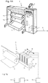
- Fig. 1A shows an image forming apparatus 1, wherein printing is achieved using a wide format inkjet printer.
- the wide-format image forming apparatus 1 comprises a housing 2, wherein the printing assembly, for example the ink jet printing assembly shown in Fig. 1B is placed.
- the image forming apparatus 1 also comprises a storage means for storing image receiving member 3, 4, a delivery station to collect the image receiving member 3, 4 after printing and storage means 5 for marking material.
- the delivery station is embodied as a delivery tray 6.
- the delivery station may comprise processing means for processing the image receiving member 3, 4 after printing, e.g. a folder or a puncher.
- the wide-format image forming apparatus 1 furthermore comprises means for receiving print jobs and optionally means for manipulating print jobs. These means may include a user interface unit 8 and/or a control unit 7, for example a computer.
- Images are printed on an image receiving member, for example paper, supplied by a roll 3, 4.
- the roll 3 is supported on the roll support R1, while the roll 4 is supported on the roll support R2.
- cut sheet image receiving members may be used instead of rolls 3, 4 of image receiving member.
- Printed sheets of the image receiving member, cut off from the roll 3, 4, are deposited in the delivery tray 6.
- Each one of the marking materials for use in the printing assembly are stored in four containers 5 arranged in fluid connection with the respective print heads for supplying marking material to said print heads.
- the local user interface unit 8 is integrated to the print engine and may comprise a display unit and a control panel. Alternatively, the control panel may be integrated in the display unit, for example in the form of a touch-screen control panel.
- the local user interface unit 8 is connected to a control unit 7 placed inside the printing apparatus 1.
- the control unit 7, for example a computer comprises a processor adapted to issue commands to the print engine, for example for controlling the print process.
- the image forming apparatus 1 may optionally be connected to a network N.
- the connection to the network N is diagrammatically shown in the form of a cable 9, but nevertheless, the connection could be wireless.
- the image forming apparatus 1 may receive printing jobs via the network. Further, optionally, the controller of the printer may be provided with a USB port, so printing jobs may be sent to the printer via this USB port.
- Fig. 1B shows an ink jet printing assembly 10.
- the ink jet printing assembly 10 comprises supporting means for supporting an image receiving member 3.
- the supporting means 11 are shown in Fig. 1B as a platen 11, but alternatively, the supporting means 11 may be a flat surface.
- the platen 11, as depicted in Fig. 1B is a rotatable drum 11, which is rotatable about its axis as indicated by arrow A.
- the supporting means 11 may be optionally provided with suction holes for holding the image receiving member 3 in a fixed position with respect to the supporting means 11.
- the inkjet printing assembly 10 comprises print heads 12a - 12d, mounted on a scanning print carriage 13.
- the scanning print carriage 13 is guided by suitable guiding means 14, 15 to move in reciprocation in the main scanning direction B.
- Each print head 12a - 12d comprises an orifice surface 16, which orifice surface 16 is provided with at least one orifice 17.
- the print heads 12a - 12d are configured to eject droplets of marking material onto the image receiving member 3.
- the platen 11, the carriage 13 and the print heads 12a - 12d are controlled by suitable controlling means 18a, 18b and 18c, respectively.
- the image receiving member 3 may be a medium in web or in sheet form and may be composed of e.g. paper, cardboard, label stock, coated paper, plastic, canvas, film or textile. Alternatively, the image receiving member 3 may also be an intermediate member, endless or not. Examples of endless members, which may be moved cyclically, are a belt or a drum.
- the image receiving member 3 is moved in the sub-scanning direction A by the platen 11 along four print heads 12a - 12d provided with a fluid marking material.
- a scanning print carriage 13 carries the four print heads 12a - 12d and may be moved in reciprocation in the main scanning direction B parallel to the platen 11, such as to enable scanning of the image receiving member 3 in the main scanning direction B.
- print heads 12a - 12d Only four print heads 12a - 12d are depicted for demonstrating the invention. In practice an arbitrary number of print heads may be employed. In any case, at least one print head 12a - 12d per color of marking material is placed on the scanning print carriage 13. For example, for a black-and-white printer, at least one print head 12a - 12d, usually containing black marking material is present. Alternatively, a black-and-white printer may comprise a white marking material, which is to be applied on a black image-receiving member 3. For a full-color printer, containing multiple colors, at least one print head 12a - 12d for each of the colors, usually black, cyan, magenta and yellow is present.
- black marking material is used more frequently in comparison to differently colored marking material. Therefore, more print heads 12a - 12d containing black marking material may be provided on the scanning print carriage 13 compared to print heads 12a - 12d containing marking material in any of the other colors. Alternatively, the print head 12a - 12d containing black marking material may be larger than any of the print heads 12a - 12d, containing a differently colored marking material.
- the carriage 13 is guided by guiding means 14, 15.
- These guiding means 14, 15 may be rods as depicted in Fig. 1B .
- the rods may be driven by suitable driving means (not shown).
- the carriage 13 may be guided by other guiding means, such as an arm being able to move the carriage 13.
- Another alternative is to move the image receiving material 3 in the main scanning direction B.
- Each print head 12a - 12d comprises an orifice surface 16 having at least one orifice 17, in fluid communication with a pressure chamber containing fluid marking material provided in the print head 12a - 12d.
- a number of orifices 17 is arranged in a single linear array parallel to the sub-scanning direction A.
- Eight orifices 17 per print head 12a - 12d are depicted in Fig. 1B , however obviously in a practical embodiment several hundreds of orifices 17 may be provided per print head 12a - 12d, optionally arranged in multiple arrays. As depicted in Fig.
- the respective print heads 12a - 12d are placed parallel to each other such that corresponding orifices 17 of the respective print heads 12a - 12d are positioned in-line in the main scanning direction B.
- a line of image dots in the main scanning direction B may be formed by selectively activating up to four orifices 17, each of them being part of a different print head 12a - 12d.
- This parallel positioning of the print heads 12a - 12d with corresponding in-line placement of the orifices 17 is advantageous to increase productivity and/or improve print quality.
- multiple print heads 12a - 12d may be placed on the print carriage adjacent to each other such that the orifices 17 of the respective print heads 12a - 12d are positioned in a staggered configuration instead of in-line. For instance, this may be done to increase the print resolution or to enlarge the effective print zone, which may be addressed in a single scan in the main scanning direction.
- the image dots are formed by ejecting droplets of marking material from the orifices 17.
- marking material Upon ejection of the marking material, some marking material may be spilled and stay on the orifice surface 16 of the print head 12a - 12d.
- the ink present on the orifice surface 16, may negatively influence the ejection of droplets and the placement of these droplets on the image receiving member 3. Therefore, it may be advantageous to remove excess of ink from the orifice surface 16.
- the excess of ink may be removed for example by wiping with a wiper and/or by application of a suitable anti-wetting property of the surface, e.g. provided by a coating.
- Figures 2A shows schematically an embodiment of an apparatus for processing a web according to the present invention.
- Figure 2A shows a side view of the apparatus 80.
- Figure 2B shows a plane view on the support platen of the apparatus 80.
- the apparatus 80 comprises a processing station 10, such as a print station comprising a carriage and a print head assembly as shown in Figure 1B , a support platen 11 facing the processing station, a transport device 20, which is a nip comprising a driven roller 22 and a pressure roller 24, and a control unit 100.
- the apparatus 80 may further comprise a radiation curing station 30 for emitting a radiation onto the web W for curing an ink applied on a process surface of the web W downstream of the processing station 10.
- the transport device 20 is arranged downstream of a processing unit 10, such as a print head assembly, and transports a web W along a transport path in a transport direction T along the processing unit 10, optionally including transporting the web W along the radiation curing station 30.
- the web is supplied from a roll 3, which is supported by a spindle 26.
- the web is moved by the transport nip 20 along the transport path from the supply roll 3 along the processing unit 10 towards a receiving roll 6.
- the receiving roll 6 is supported on a spindle 28.
- the print head assembly 10 of the processing station faces the support plate 11, which is optionally arranged to attract the web to the support plate by applying a suction force to a contact side of the web W.
- the web transport assembly further comprises a control unit 100, which is operatively connected to the print head assembly 10, the radiation curing station 30 and to the transport device 20.
- a pair of side guards 40A and 40B is positioned on the support platen 11 and connected to the support platen 11 to guide side edges S 1 , S 2 of the web W, respectively.
- the guards 40A, 40B are arranged at the side edges S 1 , S 2 , respectively, of the web W with respect to the transverse direction C perpendicular to the transport path, i.e. perpendicular to the transport direction T.
- Each of the guards 40A, 40B may comprise a connecting portion for connecting the guard 40A, 40B to the support platen 11, such as a connecting pin protruding in a direction perpendicular to the plane of the support platen 11 or a screw for fastening the guard 40A, 40B the support platen.
- the support platen may comprise a receiving portion, such as a hole shaped for receiving and retaining a connecting pin or a screw.
- the receiving portion may comprise a groove shaped for receiving and retaining a connecting portion of the guard while allowing a sliding movement of the guard in a direction parallel to the plane of the support platen 11. Said groove 19, which is shown in Figure 2B , is directed along the transverse direction C perpendicular to the transport path.
- a guard 40A, 40B may be positioned along the groove 19 by a sliding movement to position the respective guard 40A, 40B relative to the transport path of the web W based on a width of the web W across the transport path (i.e. in the transverse direction C).
- the guards 40A, 40B are suitably positioned on the support platen 11 to guide the side edges S 1 , S 2 of the web W in the transport direction T along the transport path over the support platen 11.
- Each of the pair of side guards 40A, 40B is selected from a first guard 140 and a second guard 240, which are shown in Figure 4.
- Figure 4 shows a kit comprising the first guard 140 and the second guard 240, respectively, in an assembled state wherein the guard 140, 240 is connected to the support platen 11.
- each of the first guard 140 and the second guard 240 comprises a guard portion 142, 242, a bridging portion 144, 244 and a contact portion 146, 246.
- the contact portion is arranged for contacting the support platen 11.
- the bridging portion 144, 244 is shaped for raising the guard portion away from the support platen 11, when the guard 140, 240 is in the assembled state, and for guiding a side edge of the web S 1 , S 2 along the transport path.
- the guard portion 142, 242 is arranged facing the support platen 11 and positioned at a predetermined gap d 1 , d 2 from the support platen 11 in the assembled state.
- Each of the guard portions 142, 242 is arranged for guarding a side edge of the web, i.e. limiting a deformation or protrusion of the side edge of the web away from the support platen 11.
- the predetermined gap d 1 of the first guard 140 is different from the predetermined gap d 2 of the second guard 240.
- d 2 is larger than d 1 .
- the second guard 240 may accommodate a web W, i.e. a side edge of the web W, having a larger thickness than a web, which may be accommodated by the first guard 140.
- each guard 140, 240 comprises a marker 148, 248, which provides an identifier for identifying the first guard 140, 240, respectively.
- the marker 148 of the first guard 140 is different from the marker 248 of the second guard 240.
- the marker 148, 248 is a binary code indicating the predetermined gap d 1 , d 2 of the first guard 140 and the second guard 240, respectively.
- each guard 140, 240 may comprise a connecting portion (not shown), such as a connecting pin, for connecting the guard 140, 240 to the support platen 11.
- each guard 140, 240 may be temporarily connected to the support platen by means of a tape or by means of a self sticking surface of the contact portion 146, 246.
- the marker 148, 248 may indicate a size of the guard portion 142, 242 in a plane parallel to the support platen 11, such as a width of the guard portion 142, 242 in a transverse direction C perpendicular to a transport path of the web, and / or may indicate a position of the edges of the guard portion 142, 242 relative to the marker 148, 248.
- each of the pair of side guards 40A, 40B is selected from a first guard 340 and a second guard 440, which are shown in Figure 5.
- Figure 5 shows a kit comprising the first guard 340 and the second guard 440, respectively, in an assembled state wherein the guard 340, 440 is connected to the support platen 11.
- the first guard 340 and the second guard 440 have the same elements as the first guard 140 and the second guard 440 shown in Figure 4 .
- each guard 340, 440 comprises a guard portion 342, 442, which is arranged facing the support platen 11, a bridging portion 344, 444 and a contact portion 346, 446.
- Each of the guard portions 142, 242 is arranged for guarding a side edge of the web, i.e. limiting a deformation or protrusion of the side edge of the web away from the support platen 11, along a guarding length L 1 and L 2 , respectively, in the transport direction T.
- the guarding length L 1 of the first guard 340 is different from the guarding length L 2 of the second guard 440.
- L 2 is larger than L 1 .
- the second guard 440 may guide a web W, i.e. a side edge of the web W, over a larger distance along the transport path of the web, i.e. in the transport direction T.
- each guard 340, 440 comprises a marker 348, 448, which provides an identifier for identifying the first guard 340, 440, respectively.
- the marker 348 of the first guard 340 is different from the marker 448 of the second guard 440.
- the marker 348, 448 is a binary code indicating the guarding length L 1 , L 2 of the first guard 340 and the second guard 440, respectively.
- the control unit 100 of the apparatus 80 may adjust a processing parameter, such as a processing area 110, of the processing station 10 based on detection of the marker 148, 248, 348, 448, respectively and knowledge of the position of the guarding portion 142, 242, 348, 448 relative to the support platen 11.
- a processing parameter such as a processing area 110
- the processing station 10 comprises a detector arranged for detecting a marker 148, 248, 348, 448 of the guard 40A, 40B positioned and connected to the support platen 11.
- the detector may be mounted on a carriage of the printing station 10, such as the carriage 13 shown in figure 1B .
- the detector is operatively connected to the control unit 100 to provide a detection signal to the control unit 100 indicating the detected marker 148, 248, 348, 448 of the guard 40A, 40B.
- the control unit 100 is configured for identifying the guard 40A, 40B, i.e. determining which of the first guard 140, 340 and the second guard 240, 440 is connected to the support platen 11.
- the control unit 100 is connected to a database comprising a list of markers, each being related to a specific guard 140, 240, 340, 440, the database including shape attributes of the specific guard 140, 240, 340, 440, such as predetermined gap d 1 , d 2 and / or size of the guard portion 142, 242, 342, 442, such as guarding length L 1 , L 2 .
- control unit 100 may be configured to check an orientation of the connected guard 40A, 40B relative to the support platen 11 based on the detected marker 148, 248, 348, 448. In an example, the control unit 100 may check, how the guard portion 142, 242 of each of the left guard 40A and the right guard 40B, relative to the transport direction, is arranged relative to the contact portion 146, 246 to correctly guide the respective side edge S 1 , S 2 of the web W along the transport path.
- Figures 3 shows in a flow diagram an embodiment of a method for processing a web in an apparatus 80 according to the present invention.
- a guard is selected from a first guard 140 and a second guard 240 by an operator of the apparatus 80 based on a web W to be processed by the apparatus.
- the operator selects the guard based on a thickness of the web and based on a predetermined distance d 1 , d 2 of the first guard 140 and the second guard 240, respectively.
- the operator selects the same type of guard for both side edges S 1 , S 2 of the web, as the thickness of the web is substantially independent of the specific edge of the web W.
- a next step S304 the operator connects the selected guard (140 or 240) to the support platen 11 at a desired position relative to the transverse direction c to guide a respective edge S 1 , S 2 of the web W.
- the guard 140, 240 may be connected to the support platen 11 by using a connecting portion of the guard 140, 240.
- the guard 140, 240 may be connected to the support platen 11 by applying tape to the contacting portion 146, 246 of the first guard 140 or the second guard 240, respectively.
- a presence of the connected guard at the support platen 11 is determined by the apparatus 80.
- the apparatus comprises a cover arranged for providing an entry for the operator to the support platen 11, when arranged in an opening state.
- the control unit 100 is operatively connected to the cover to determine the opening state and / or closing state of the cover. In case the cover is moved in the opening state by the operator, the control unit 100 assumes that a guard is to be connected to the support platen 11.
- the control unit 100 may move the processing station 10 away from the support platen 11, e.g. in a plane parallel to the support platen, to support access of the operator to the support platen 11.
- control unit 100 may raise the processing station 10 to a predetermined safe distance above the support platen 11, i.e. in a direction perpendicular to the plane of the support platen 11, to avoid any damage occurring to the processing station 10 during any further movements of the processing station over the support platen 11.
- the presence of the connected guard 40A, 40B may be communicated to the control unit 100 of the apparatus 80 by an operator input, such as by using an input device of the apparatus.
- the connected guard 40A, 40B is identified.
- the identification of the connected guard may be carried out by using a detector mounted on a carriage of the printing station 10, such as the carriage 13 shown in figure 1B .
- the detector is operatively connected to the control unit 100 to provide a detection signal to the control unit 100 indicating a detected marker 148, 248 of the guard 140, 240.
- the operator may identify the connected guard 40A, 40B, e.g. as the guard is also selected by the operator.
- the operator may provide an operator input to the control unit 100 of the apparatus to communicate the identity of the connected guard 40A, 40B.
- the position of the connected guard 40A, 40B is determined.
- the position of the guard 40A, 40B on the support platen 11 may be determined by the detector for detecting the guard 40A, 40B.
- the detector detects the detected marker 148, 248 of the guard 140, 240 and provides a detection signal to the control unit 100 based on the detected marker 148, 248.
- the control unit 100 determines the position of the connected guard 40A, 40B based on the position of the detected marker 148, 248.
- control unit 100 may determine a position of the guard portion 142, 242 relative to the support platen 11 based on the detected marker 148, 248 and further based on a known distance between the marker 148, 248 and side edges of the guard portion 142, 242. In this way, the control unit 100 exactly knows the position of the guard portion relative to the support platen, both in a direction of the plane of the support platen 11 and in a height direction perpendicular to the plane of the support platen 11.
- the control unit 100 adjusts a processing parameter of the processing station 10.
- a gap between the processing station and the support platen, which is maintained during processing of the web is adjusted based on a predetermined distance d1, d2 of the selected guard 140, 240.
- d1, d2 of the selected guard 140, 240 a collision of the processing station 10, such as a moveable print station, to the connected guard 40A, 40B is avoided while optimizing a processing distance between the processing station 10 and the web W.
- the print area 110 relative to the support platen 11 to be processed by the printing station 10 is adjusted based on the determined presence of the connected guard.
- the guard is polluted by an ink to form an image, which ink is printed by the print station 10 onto the web W in the print area 110.
- the ink is a radiation curable ink
- such ink may provide a safety risk, when the ink pollutes the connected guard and is not cured by a radiation source 30, which is arranged away from the support platen 11 facing the print station 10, such as downstream from the print station 10 in a transport direction T of the web W.
- step S314 the web W is processed according to the adjusted processing parameter, as adjusted in step S312. In this way, an optimised processing of the web w is obtained.
- the method can be reiterated by an operator by starting again from step S302 and performing the steps S302 - 314, wherein another guard is selected from a first guard 140, 340 and a second guard 240, 440, shown in Figures 4 and 5 , based on another web to be processed by the apparatus 80.
- structural elements may be generated by application of three-dimensional (3D) printing techniques. Therefore, any reference to a structural element is intended to encompass any computer executable instructions that instruct a computer to generate such a structural element by three-dimensional printing techniques or similar computer controlled manufacturing techniques. Furthermore, such a reference to a structural element encompasses a computer readable medium carrying such computer executable instructions.
- the terms and phrases used herein are not intended to be limiting; but rather, to provide an understandable description of the invention.
- the terms "a” or “an”, as used herein, are defined as one or more than one.
- the term plurality, as used herein, is defined as two or more than two.
- the term another, as used herein, is defined as at least a second or more.
- the terms including and/or having, as used herein, are defined as comprising (i.e., open language).
- the term coupled, as used herein, is defined as connected, although not necessarily directly.
Landscapes
- Handling Of Sheets (AREA)
- Accessory Devices And Overall Control Thereof (AREA)
Claims (15)
- Appareil d'impression (1) comprenant :- une station d'impression (10) pour traiter une bande ;- un dispositif de transport (20) pour transporter la bande à travers un trajet de transport le long de la station d'impression (10) ;- une platine de support (11) faisant face à la station d'impression (10) pour supporter la bande, lorsqu'elle est traitée par la station d'impression (10) ;- une première protection (40A, 40B) pour protéger un bord latéral d'une bande, la première protection pouvant être raccordée à la platine de support (11) pour guider la bande le long du trajet de transport, lorsque la bande est traitée par la station d'impression (10) ;- un détecteur pour détecter la première protection (40A, 40B) lorsqu'elle est raccordée à la platine de support (11) ;- une unité de commande (100) configurée pour commander la station d'impression (10) pour traiter la bande, dans lequel l'unité de commande (100) est configurée pour identifier et déterminer des informations de forme et/ou de taille, spécifiquement des informations de hauteur et/ou de position, de la protection (40A, 40B) sur la base d'un signal de détection fourni par le détecteur à l'unité de commande (100), et- un chariot mobile (13) pour déplacer la station d'impression (10) par rapport à la platine de support (11) dans une direction sur le trajet de transport, dans lequel la station d'impression (10) est montée sur le chariot (13), dans lequel l'unité de commande (100) est configurée pour commander le mouvement du chariot (13) pour empêcher un contact entre la station d'impression (10) et la protection (40A, 40B) raccordée à la platine de support (11) sur la base des informations déterminées.
- Appareil selon la revendication 1, dans lequel le détecteur est monté sur la chariot.
- Appareil selon la revendication 1 ou 2, dans lequel la première protection comprend en outre- une base de raccordement pouvant être raccordée à la platine de support- une plaque de limiteur pour limiter une déformation de la bande dans une direction opposée à la platine de support ; et- un dispositif d'espacement raccordant la base de raccordement à la plaque de limiteur, le dispositif d'espacement étant configuré pour positionner la plaque de limiteur à une distance prédéfinie de la platine de support lorsque la base de raccordement est raccordée à la platine de support.
- Appareil selon l'une quelconque des revendications précédentes, dans lequel l'unité de commande est configurée pour déterminer la position de la protection raccordée par rapport à la platine de support.
- Appareil selon l'une quelconque des revendications précédentes, dans lequel la station d'impression est agencée présentant un écart par rapport à la platine de support durant le traitement de la bande et dans lequel l'unité de commande est configurée pour ajuster un écart sur la base d'une identité de la protection identifiée.
- Appareil selon l'une quelconque des revendications précédentes, dans lequel l'unité de commande comprend une mémoire stockant un tableau d'identité, dans lequel l'unité de commande est agencée pour sélectionner une protection à partir du tableau d'identité sur la base du signal de détection.
- Appareil selon l'une quelconque des revendications précédentes, dans lequel la première protection comprend un attribut d'identifiant pour identifier la protection.
- Appareil selon la revendication 7, dans lequel l'attribut d'identifiant comprend un marqueur sur la première protection.
- Appareil selon la revendication 8, dans lequel le marqueur comprend des informations d'identité lisibles par le détecteur.
- Appareil selon la revendication 9, dans lequel l'attribut d'identifiant comprend une couleur de la première protection.
- Appareil selon l'une quelconque des revendications précédentes, dans lequel les informations comprennent une dimension de hauteur de la protection.
- Première protection pour une utilisation dans l'appareil d'impression selon l'une quelconque des revendications précédentes, comprenant un attribut d'identifiant lisible par le détecteur pour identifier et déterminer les informations de forme et/ou de taille, spécifiquement des informations de hauteur et/ou de position de la protection.
- Procédé de commande d'une station d'impression (10) dans un appareil d'impression de bande (1), le procédé comprenant les étapes consistant à :- détecter, par un détecteur, une première protection (40A, 40B) pour protéger un bord latéral d'une bande lorsqu'elle est raccordée à une platine de support (11) de l'appareil d'impression (1) ;- identifier et déterminer des informations de forme et/ou de taille, spécifiquement des informations de hauteur et/ou de position de la première protection (40A, 40B) sur la base de données générées par le détecteur ;- commander le mouvement de la station d'impression (10) pour éviter un contact avec la première protection identifiée (40A, 40B) sur la base des informations déterminées.
- Procédé selon la revendication 13, comprenant en outre les étapes consistant à :- déterminer une hauteur de la première protection identifiée ; et- ajuster un écart entre la station d'impression et la platine de support sur la base de la hauteur déterminée.
- Procédé selon la revendication 13 ou 14, comprenant en outre les étapes consistant à :- déterminer une position de la première protection identifiée ; et- commander un mouvement translationnel de la station d'impression sur la platine de support, de sorte que la station d'impression évite la position déterminée.
Applications Claiming Priority (1)
| Application Number | Priority Date | Filing Date | Title |
|---|---|---|---|
| EP16192128 | 2016-10-04 |
Publications (2)
| Publication Number | Publication Date |
|---|---|
| EP3305533A1 EP3305533A1 (fr) | 2018-04-11 |
| EP3305533B1 true EP3305533B1 (fr) | 2021-02-17 |
Family
ID=57137835
Family Applications (1)
| Application Number | Title | Priority Date | Filing Date |
|---|---|---|---|
| EP17192344.4A Active EP3305533B1 (fr) | 2016-10-04 | 2017-09-21 | Procédé de traitement d'une bande dans un appareil |
Country Status (2)
| Country | Link |
|---|---|
| US (1) | US10589546B2 (fr) |
| EP (1) | EP3305533B1 (fr) |
Families Citing this family (3)
| Publication number | Priority date | Publication date | Assignee | Title |
|---|---|---|---|---|
| IT201900018722A1 (it) * | 2019-10-14 | 2021-04-14 | Ms Printing Solutions S R L | Dispositivo e procedimento di trattamento di materiale in foglio, impianto e procedimento di stampa di materiale in foglio |
| EP4076966A4 (fr) * | 2019-12-20 | 2023-09-06 | Hewlett-Packard Development Company, L.P. | Impression avec des changements de rouleau de support et des trames de non-production |
| EP4082950A4 (fr) * | 2019-12-25 | 2024-01-10 | Brother Ind Ltd | Dispositif de transport de plaque |
Family Cites Families (23)
| Publication number | Priority date | Publication date | Assignee | Title |
|---|---|---|---|---|
| DE4132652C2 (de) | 1991-10-01 | 1995-04-27 | Flachglas Ag | Verfahren zur Herstellung einer einfachgekrümmten oder einer doppeltgekrümmten Verbundglasscheibe, insbesondere für Kraftfahrzeuge |
| US5513920A (en) * | 1992-10-29 | 1996-05-07 | Eastman Kodak Company | Dye donor web loading apparatus for a thermal printer |
| US5761070A (en) * | 1995-11-02 | 1998-06-02 | Virginia Tech Intellectual Properties, Inc. | Automatic color and grain sorting of materials |
| US6226094B1 (en) * | 1996-01-05 | 2001-05-01 | King Jim Co., Ltd. | Apparatus and method for processing character information |
| WO1997032730A1 (fr) * | 1996-03-04 | 1997-09-12 | Copyer Co., Ltd. | Acheminement d'un support d'enregistrement |
| US6594407B2 (en) * | 2001-03-06 | 2003-07-15 | Fujitsu Limited | Optical modulator of clock modulation type |
| US6742948B2 (en) * | 2001-10-22 | 2004-06-01 | Aprion Digital Ltd. | Apparatus for flattening a substrate and method thereof |
| JP3972829B2 (ja) * | 2003-01-31 | 2007-09-05 | コニカミノルタホールディングス株式会社 | インクジェットプリンタの記録紙押さえ構造 |
| US20050271449A1 (en) * | 2004-02-02 | 2005-12-08 | Zih Corp. | Front loading printer with center justified print |
| US7594771B2 (en) * | 2004-12-22 | 2009-09-29 | Eastman Kodak Company | Spool adapter |
| JP4192918B2 (ja) * | 2005-05-27 | 2008-12-10 | セイコーエプソン株式会社 | カッティング装置およびシート処理装置 |
| US7037011B1 (en) * | 2005-07-07 | 2006-05-02 | Amano Cincinnati, Inc. | Ribbon cartridge having updatable data communication component |
| RU2533666C2 (ru) * | 2009-03-31 | 2014-11-20 | Бразер Когио Кабусики Кайся | Кассета с лентой и ленточный принтер |
| JP2010264596A (ja) * | 2009-05-12 | 2010-11-25 | Konica Minolta Ij Technologies Inc | インクジェット記録装置 |
| US8408671B2 (en) * | 2009-07-30 | 2013-04-02 | Roland Dg Corporation | Ink jet recording apparatus equipped with ultraviolet light irradiation device |
| JP5440027B2 (ja) * | 2009-08-27 | 2014-03-12 | セイコーエプソン株式会社 | 搬送装置及び記録装置 |
| JP5552935B2 (ja) * | 2010-07-21 | 2014-07-16 | セイコーエプソン株式会社 | 保持部材の取付位置の確認方法、及び記録装置 |
| JP5887792B2 (ja) * | 2011-09-22 | 2016-03-16 | 富士通株式会社 | プリンタおよびその印刷制御プログラム |
| US9028160B2 (en) * | 2011-11-29 | 2015-05-12 | Hewlett-Packard Development Company, L.P. | Print substrate edge guide |
| JP6024426B2 (ja) * | 2012-12-04 | 2016-11-16 | ブラザー工業株式会社 | 印刷媒体および印刷装置 |
| JP6070279B2 (ja) * | 2013-03-04 | 2017-02-01 | セイコーエプソン株式会社 | 記録装置 |
| CN105934351B (zh) * | 2014-01-30 | 2018-01-16 | 惠普发展公司,有限责任合伙企业 | 用于打印机的系统、打印机以及打印承印物边缘引导件 |
| JP6428111B2 (ja) * | 2014-09-30 | 2018-11-28 | セイコーエプソン株式会社 | 媒体押さえ部材、及び記録装置 |
-
2017
- 2017-09-21 EP EP17192344.4A patent/EP3305533B1/fr active Active
- 2017-09-26 US US15/715,734 patent/US10589546B2/en active Active
Non-Patent Citations (1)
| Title |
|---|
| None * |
Also Published As
| Publication number | Publication date |
|---|---|
| EP3305533A1 (fr) | 2018-04-11 |
| US20180093497A1 (en) | 2018-04-05 |
| US10589546B2 (en) | 2020-03-17 |
Similar Documents
| Publication | Publication Date | Title |
|---|---|---|
| US9840090B2 (en) | Flatbed printer assembly | |
| EP3305533B1 (fr) | Procédé de traitement d'une bande dans un appareil | |
| US9592685B2 (en) | Scanning inkjet printing system | |
| US10118412B2 (en) | Scanning inkjet printing assembly | |
| US9120342B2 (en) | Method for full bleed printing | |
| US10377128B2 (en) | Method for controlling a web in a printing apparatus | |
| CN104070837A (zh) | 连续进给打印机中的皱折检测 | |
| US9862213B2 (en) | Scanning inkjet printing system | |
| US10131163B2 (en) | Vacuum level calibration for a web-based printer | |
| US20080192270A1 (en) | Transport amount correcting method, transport amount correcting apparatus, and storage medium having program stored thereon | |
| EP3301047B1 (fr) | Ensemble de transport d'une bande le long d'une unité de traitement | |
| JP6040241B2 (ja) | 連続するスワスを印刷する方法 | |
| US10245854B2 (en) | Determining printer platen type | |
| EP3366481B1 (fr) | Système d'impression comportant un dispositif de formation de blouse pour support en bande rigide | |
| NL2023115B1 (en) | Vacuum level calibration for a web-based printer | |
| EP2949476A1 (fr) | Appareil et procede de formation d'image permettant de compenser l'oscillation d'un rouleau dans un appareil de formation d'image | |
| EP3613597A1 (fr) | Correction d'erreurs cycliques dépendant de la largeur dans une impression à rouleau | |
| NL2022181B1 (en) | Web portion removal aid for wide format web printers | |
| JP2018144263A (ja) | 記録装置および記録方法 | |
| US20150231900A1 (en) | Method for forming an inkjet image | |
| JP2015168204A (ja) | 画像形成装置 |
Legal Events
| Date | Code | Title | Description |
|---|---|---|---|
| PUAI | Public reference made under article 153(3) epc to a published international application that has entered the european phase |
Free format text: ORIGINAL CODE: 0009012 |
|
| STAA | Information on the status of an ep patent application or granted ep patent |
Free format text: STATUS: THE APPLICATION HAS BEEN PUBLISHED |
|
| AK | Designated contracting states |
Kind code of ref document: A1 Designated state(s): AL AT BE BG CH CY CZ DE DK EE ES FI FR GB GR HR HU IE IS IT LI LT LU LV MC MK MT NL NO PL PT RO RS SE SI SK SM TR |
|
| AX | Request for extension of the european patent |
Extension state: BA ME |
|
| STAA | Information on the status of an ep patent application or granted ep patent |
Free format text: STATUS: REQUEST FOR EXAMINATION WAS MADE |
|
| 17P | Request for examination filed |
Effective date: 20181011 |
|
| RBV | Designated contracting states (corrected) |
Designated state(s): AL AT BE BG CH CY CZ DE DK EE ES FI FR GB GR HR HU IE IS IT LI LT LU LV MC MK MT NL NO PL PT RO RS SE SI SK SM TR |
|
| STAA | Information on the status of an ep patent application or granted ep patent |
Free format text: STATUS: EXAMINATION IS IN PROGRESS |
|
| RAP1 | Party data changed (applicant data changed or rights of an application transferred) |
Owner name: CANON PRODUCTION PRINTING HOLDING B.V. |
|
| 17Q | First examination report despatched |
Effective date: 20200305 |
|
| GRAP | Despatch of communication of intention to grant a patent |
Free format text: ORIGINAL CODE: EPIDOSNIGR1 |
|
| STAA | Information on the status of an ep patent application or granted ep patent |
Free format text: STATUS: GRANT OF PATENT IS INTENDED |
|
| GRAJ | Information related to disapproval of communication of intention to grant by the applicant or resumption of examination proceedings by the epo deleted |
Free format text: ORIGINAL CODE: EPIDOSDIGR1 |
|
| STAA | Information on the status of an ep patent application or granted ep patent |
Free format text: STATUS: EXAMINATION IS IN PROGRESS |
|
| INTG | Intention to grant announced |
Effective date: 20200720 |
|
| INTC | Intention to grant announced (deleted) | ||
| GRAP | Despatch of communication of intention to grant a patent |
Free format text: ORIGINAL CODE: EPIDOSNIGR1 |
|
| STAA | Information on the status of an ep patent application or granted ep patent |
Free format text: STATUS: GRANT OF PATENT IS INTENDED |
|
| INTG | Intention to grant announced |
Effective date: 20200923 |
|
| RAP1 | Party data changed (applicant data changed or rights of an application transferred) |
Owner name: CANON PRODUCTION PRINTING HOLDING B.V. |
|
| GRAS | Grant fee paid |
Free format text: ORIGINAL CODE: EPIDOSNIGR3 |
|
| GRAA | (expected) grant |
Free format text: ORIGINAL CODE: 0009210 |
|
| STAA | Information on the status of an ep patent application or granted ep patent |
Free format text: STATUS: THE PATENT HAS BEEN GRANTED |
|
| AK | Designated contracting states |
Kind code of ref document: B1 Designated state(s): AL AT BE BG CH CY CZ DE DK EE ES FI FR GB GR HR HU IE IS IT LI LT LU LV MC MK MT NL NO PL PT RO RS SE SI SK SM TR |
|
| REG | Reference to a national code |
Ref country code: GB Ref legal event code: FG4D |
|
| REG | Reference to a national code |
Ref country code: CH Ref legal event code: EP |
|
| REG | Reference to a national code |
Ref country code: DE Ref legal event code: R096 Ref document number: 602017032546 Country of ref document: DE |
|
| REG | Reference to a national code |
Ref country code: AT Ref legal event code: REF Ref document number: 1360982 Country of ref document: AT Kind code of ref document: T Effective date: 20210315 |
|
| REG | Reference to a national code |
Ref country code: IE Ref legal event code: FG4D |
|
| REG | Reference to a national code |
Ref country code: NL Ref legal event code: FP |
|
| REG | Reference to a national code |
Ref country code: LT Ref legal event code: MG9D |
|
| PG25 | Lapsed in a contracting state [announced via postgrant information from national office to epo] |
Ref country code: FI Free format text: LAPSE BECAUSE OF FAILURE TO SUBMIT A TRANSLATION OF THE DESCRIPTION OR TO PAY THE FEE WITHIN THE PRESCRIBED TIME-LIMIT Effective date: 20210217 Ref country code: GR Free format text: LAPSE BECAUSE OF FAILURE TO SUBMIT A TRANSLATION OF THE DESCRIPTION OR TO PAY THE FEE WITHIN THE PRESCRIBED TIME-LIMIT Effective date: 20210518 Ref country code: HR Free format text: LAPSE BECAUSE OF FAILURE TO SUBMIT A TRANSLATION OF THE DESCRIPTION OR TO PAY THE FEE WITHIN THE PRESCRIBED TIME-LIMIT Effective date: 20210217 Ref country code: PT Free format text: LAPSE BECAUSE OF FAILURE TO SUBMIT A TRANSLATION OF THE DESCRIPTION OR TO PAY THE FEE WITHIN THE PRESCRIBED TIME-LIMIT Effective date: 20210617 Ref country code: NO Free format text: LAPSE BECAUSE OF FAILURE TO SUBMIT A TRANSLATION OF THE DESCRIPTION OR TO PAY THE FEE WITHIN THE PRESCRIBED TIME-LIMIT Effective date: 20210517 Ref country code: BG Free format text: LAPSE BECAUSE OF FAILURE TO SUBMIT A TRANSLATION OF THE DESCRIPTION OR TO PAY THE FEE WITHIN THE PRESCRIBED TIME-LIMIT Effective date: 20210517 Ref country code: LT Free format text: LAPSE BECAUSE OF FAILURE TO SUBMIT A TRANSLATION OF THE DESCRIPTION OR TO PAY THE FEE WITHIN THE PRESCRIBED TIME-LIMIT Effective date: 20210217 |
|
| REG | Reference to a national code |
Ref country code: AT Ref legal event code: MK05 Ref document number: 1360982 Country of ref document: AT Kind code of ref document: T Effective date: 20210217 |
|
| PG25 | Lapsed in a contracting state [announced via postgrant information from national office to epo] |
Ref country code: PL Free format text: LAPSE BECAUSE OF FAILURE TO SUBMIT A TRANSLATION OF THE DESCRIPTION OR TO PAY THE FEE WITHIN THE PRESCRIBED TIME-LIMIT Effective date: 20210217 Ref country code: RS Free format text: LAPSE BECAUSE OF FAILURE TO SUBMIT A TRANSLATION OF THE DESCRIPTION OR TO PAY THE FEE WITHIN THE PRESCRIBED TIME-LIMIT Effective date: 20210217 Ref country code: LV Free format text: LAPSE BECAUSE OF FAILURE TO SUBMIT A TRANSLATION OF THE DESCRIPTION OR TO PAY THE FEE WITHIN THE PRESCRIBED TIME-LIMIT Effective date: 20210217 Ref country code: SE Free format text: LAPSE BECAUSE OF FAILURE TO SUBMIT A TRANSLATION OF THE DESCRIPTION OR TO PAY THE FEE WITHIN THE PRESCRIBED TIME-LIMIT Effective date: 20210217 |
|
| PG25 | Lapsed in a contracting state [announced via postgrant information from national office to epo] |
Ref country code: IS Free format text: LAPSE BECAUSE OF FAILURE TO SUBMIT A TRANSLATION OF THE DESCRIPTION OR TO PAY THE FEE WITHIN THE PRESCRIBED TIME-LIMIT Effective date: 20210617 |
|
| PG25 | Lapsed in a contracting state [announced via postgrant information from national office to epo] |
Ref country code: EE Free format text: LAPSE BECAUSE OF FAILURE TO SUBMIT A TRANSLATION OF THE DESCRIPTION OR TO PAY THE FEE WITHIN THE PRESCRIBED TIME-LIMIT Effective date: 20210217 Ref country code: CZ Free format text: LAPSE BECAUSE OF FAILURE TO SUBMIT A TRANSLATION OF THE DESCRIPTION OR TO PAY THE FEE WITHIN THE PRESCRIBED TIME-LIMIT Effective date: 20210217 Ref country code: AT Free format text: LAPSE BECAUSE OF FAILURE TO SUBMIT A TRANSLATION OF THE DESCRIPTION OR TO PAY THE FEE WITHIN THE PRESCRIBED TIME-LIMIT Effective date: 20210217 Ref country code: SM Free format text: LAPSE BECAUSE OF FAILURE TO SUBMIT A TRANSLATION OF THE DESCRIPTION OR TO PAY THE FEE WITHIN THE PRESCRIBED TIME-LIMIT Effective date: 20210217 |
|
| REG | Reference to a national code |
Ref country code: DE Ref legal event code: R097 Ref document number: 602017032546 Country of ref document: DE |
|
| PG25 | Lapsed in a contracting state [announced via postgrant information from national office to epo] |
Ref country code: SK Free format text: LAPSE BECAUSE OF FAILURE TO SUBMIT A TRANSLATION OF THE DESCRIPTION OR TO PAY THE FEE WITHIN THE PRESCRIBED TIME-LIMIT Effective date: 20210217 Ref country code: RO Free format text: LAPSE BECAUSE OF FAILURE TO SUBMIT A TRANSLATION OF THE DESCRIPTION OR TO PAY THE FEE WITHIN THE PRESCRIBED TIME-LIMIT Effective date: 20210217 Ref country code: DK Free format text: LAPSE BECAUSE OF FAILURE TO SUBMIT A TRANSLATION OF THE DESCRIPTION OR TO PAY THE FEE WITHIN THE PRESCRIBED TIME-LIMIT Effective date: 20210217 |
|
| PLBE | No opposition filed within time limit |
Free format text: ORIGINAL CODE: 0009261 |
|
| STAA | Information on the status of an ep patent application or granted ep patent |
Free format text: STATUS: NO OPPOSITION FILED WITHIN TIME LIMIT |
|
| 26N | No opposition filed |
Effective date: 20211118 |
|
| PG25 | Lapsed in a contracting state [announced via postgrant information from national office to epo] |
Ref country code: AL Free format text: LAPSE BECAUSE OF FAILURE TO SUBMIT A TRANSLATION OF THE DESCRIPTION OR TO PAY THE FEE WITHIN THE PRESCRIBED TIME-LIMIT Effective date: 20210217 Ref country code: ES Free format text: LAPSE BECAUSE OF FAILURE TO SUBMIT A TRANSLATION OF THE DESCRIPTION OR TO PAY THE FEE WITHIN THE PRESCRIBED TIME-LIMIT Effective date: 20210217 |
|
| PG25 | Lapsed in a contracting state [announced via postgrant information from national office to epo] |
Ref country code: SI Free format text: LAPSE BECAUSE OF FAILURE TO SUBMIT A TRANSLATION OF THE DESCRIPTION OR TO PAY THE FEE WITHIN THE PRESCRIBED TIME-LIMIT Effective date: 20210217 |
|
| PG25 | Lapsed in a contracting state [announced via postgrant information from national office to epo] |
Ref country code: IT Free format text: LAPSE BECAUSE OF FAILURE TO SUBMIT A TRANSLATION OF THE DESCRIPTION OR TO PAY THE FEE WITHIN THE PRESCRIBED TIME-LIMIT Effective date: 20210217 |
|
| REG | Reference to a national code |
Ref country code: CH Ref legal event code: PL |
|
| REG | Reference to a national code |
Ref country code: BE Ref legal event code: MM Effective date: 20210930 |
|
| GBPC | Gb: european patent ceased through non-payment of renewal fee |
Effective date: 20210921 |
|
| PG25 | Lapsed in a contracting state [announced via postgrant information from national office to epo] |
Ref country code: IS Free format text: LAPSE BECAUSE OF FAILURE TO SUBMIT A TRANSLATION OF THE DESCRIPTION OR TO PAY THE FEE WITHIN THE PRESCRIBED TIME-LIMIT Effective date: 20210617 Ref country code: MC Free format text: LAPSE BECAUSE OF FAILURE TO SUBMIT A TRANSLATION OF THE DESCRIPTION OR TO PAY THE FEE WITHIN THE PRESCRIBED TIME-LIMIT Effective date: 20210217 |
|
| PG25 | Lapsed in a contracting state [announced via postgrant information from national office to epo] |
Ref country code: LU Free format text: LAPSE BECAUSE OF NON-PAYMENT OF DUE FEES Effective date: 20210921 Ref country code: IE Free format text: LAPSE BECAUSE OF NON-PAYMENT OF DUE FEES Effective date: 20210921 Ref country code: GB Free format text: LAPSE BECAUSE OF NON-PAYMENT OF DUE FEES Effective date: 20210921 Ref country code: FR Free format text: LAPSE BECAUSE OF NON-PAYMENT OF DUE FEES Effective date: 20210930 Ref country code: BE Free format text: LAPSE BECAUSE OF NON-PAYMENT OF DUE FEES Effective date: 20210930 |
|
| PG25 | Lapsed in a contracting state [announced via postgrant information from national office to epo] |
Ref country code: LI Free format text: LAPSE BECAUSE OF NON-PAYMENT OF DUE FEES Effective date: 20210930 Ref country code: CH Free format text: LAPSE BECAUSE OF NON-PAYMENT OF DUE FEES Effective date: 20210930 |
|
| PG25 | Lapsed in a contracting state [announced via postgrant information from national office to epo] |
Ref country code: HU Free format text: LAPSE BECAUSE OF FAILURE TO SUBMIT A TRANSLATION OF THE DESCRIPTION OR TO PAY THE FEE WITHIN THE PRESCRIBED TIME-LIMIT; INVALID AB INITIO Effective date: 20170921 |
|
| PG25 | Lapsed in a contracting state [announced via postgrant information from national office to epo] |
Ref country code: CY Free format text: LAPSE BECAUSE OF FAILURE TO SUBMIT A TRANSLATION OF THE DESCRIPTION OR TO PAY THE FEE WITHIN THE PRESCRIBED TIME-LIMIT Effective date: 20210217 |
|
| PGFP | Annual fee paid to national office [announced via postgrant information from national office to epo] |
Ref country code: NL Payment date: 20230823 Year of fee payment: 7 |
|
| PGFP | Annual fee paid to national office [announced via postgrant information from national office to epo] |
Ref country code: DE Payment date: 20230920 Year of fee payment: 7 |
|
| PG25 | Lapsed in a contracting state [announced via postgrant information from national office to epo] |
Ref country code: MK Free format text: LAPSE BECAUSE OF FAILURE TO SUBMIT A TRANSLATION OF THE DESCRIPTION OR TO PAY THE FEE WITHIN THE PRESCRIBED TIME-LIMIT Effective date: 20210217 |