EP3305229A1 - Medical manipulator - Google Patents
Medical manipulator Download PDFInfo
- Publication number
- EP3305229A1 EP3305229A1 EP15894281.3A EP15894281A EP3305229A1 EP 3305229 A1 EP3305229 A1 EP 3305229A1 EP 15894281 A EP15894281 A EP 15894281A EP 3305229 A1 EP3305229 A1 EP 3305229A1
- Authority
- EP
- European Patent Office
- Prior art keywords
- section
- joint
- elongated
- connection member
- cover
- Prior art date
- Legal status (The legal status is an assumption and is not a legal conclusion. Google has not performed a legal analysis and makes no representation as to the accuracy of the status listed.)
- Withdrawn
Links
Images



Classifications
-
- A—HUMAN NECESSITIES
- A61—MEDICAL OR VETERINARY SCIENCE; HYGIENE
- A61B—DIAGNOSIS; SURGERY; IDENTIFICATION
- A61B46/00—Surgical drapes
- A61B46/10—Surgical drapes specially adapted for instruments, e.g. microscopes
-
- A—HUMAN NECESSITIES
- A61—MEDICAL OR VETERINARY SCIENCE; HYGIENE
- A61B—DIAGNOSIS; SURGERY; IDENTIFICATION
- A61B17/00—Surgical instruments, devices or methods
- A61B17/00234—Surgical instruments, devices or methods for minimally invasive surgery
-
- A—HUMAN NECESSITIES
- A61—MEDICAL OR VETERINARY SCIENCE; HYGIENE
- A61B—DIAGNOSIS; SURGERY; IDENTIFICATION
- A61B17/00—Surgical instruments, devices or methods
- A61B17/28—Surgical forceps
- A61B17/29—Forceps for use in minimally invasive surgery
-
- A—HUMAN NECESSITIES
- A61—MEDICAL OR VETERINARY SCIENCE; HYGIENE
- A61B—DIAGNOSIS; SURGERY; IDENTIFICATION
- A61B17/00—Surgical instruments, devices or methods
- A61B17/34—Trocars; Puncturing needles
- A61B17/3417—Details of tips or shafts, e.g. grooves, expandable, bendable; Multiple coaxial sliding cannulas, e.g. for dilating
- A61B17/3421—Cannulas
- A61B17/3423—Access ports, e.g. toroid shape introducers for instruments or hands
-
- A—HUMAN NECESSITIES
- A61—MEDICAL OR VETERINARY SCIENCE; HYGIENE
- A61B—DIAGNOSIS; SURGERY; IDENTIFICATION
- A61B18/00—Surgical instruments, devices or methods for transferring non-mechanical forms of energy to or from the body
- A61B18/04—Surgical instruments, devices or methods for transferring non-mechanical forms of energy to or from the body by heating
- A61B18/12—Surgical instruments, devices or methods for transferring non-mechanical forms of energy to or from the body by heating by passing a current through the tissue to be heated, e.g. high-frequency current
- A61B18/14—Probes or electrodes therefor
- A61B18/1492—Probes or electrodes therefor having a flexible, catheter-like structure, e.g. for heart ablation
-
- A—HUMAN NECESSITIES
- A61—MEDICAL OR VETERINARY SCIENCE; HYGIENE
- A61B—DIAGNOSIS; SURGERY; IDENTIFICATION
- A61B34/00—Computer-aided surgery; Manipulators or robots specially adapted for use in surgery
- A61B34/30—Surgical robots
-
- A—HUMAN NECESSITIES
- A61—MEDICAL OR VETERINARY SCIENCE; HYGIENE
- A61B—DIAGNOSIS; SURGERY; IDENTIFICATION
- A61B34/00—Computer-aided surgery; Manipulators or robots specially adapted for use in surgery
- A61B34/30—Surgical robots
- A61B34/32—Surgical robots operating autonomously
-
- A—HUMAN NECESSITIES
- A61—MEDICAL OR VETERINARY SCIENCE; HYGIENE
- A61B—DIAGNOSIS; SURGERY; IDENTIFICATION
- A61B34/00—Computer-aided surgery; Manipulators or robots specially adapted for use in surgery
- A61B34/30—Surgical robots
- A61B34/37—Leader-follower robots
-
- A—HUMAN NECESSITIES
- A61—MEDICAL OR VETERINARY SCIENCE; HYGIENE
- A61B—DIAGNOSIS; SURGERY; IDENTIFICATION
- A61B34/00—Computer-aided surgery; Manipulators or robots specially adapted for use in surgery
- A61B34/70—Manipulators specially adapted for use in surgery
-
- A—HUMAN NECESSITIES
- A61—MEDICAL OR VETERINARY SCIENCE; HYGIENE
- A61B—DIAGNOSIS; SURGERY; IDENTIFICATION
- A61B34/00—Computer-aided surgery; Manipulators or robots specially adapted for use in surgery
- A61B34/70—Manipulators specially adapted for use in surgery
- A61B34/71—Manipulators operated by drive cable mechanisms
-
- A—HUMAN NECESSITIES
- A61—MEDICAL OR VETERINARY SCIENCE; HYGIENE
- A61B—DIAGNOSIS; SURGERY; IDENTIFICATION
- A61B34/00—Computer-aided surgery; Manipulators or robots specially adapted for use in surgery
- A61B34/70—Manipulators specially adapted for use in surgery
- A61B34/74—Manipulators with manual electric input means
-
- A—HUMAN NECESSITIES
- A61—MEDICAL OR VETERINARY SCIENCE; HYGIENE
- A61B—DIAGNOSIS; SURGERY; IDENTIFICATION
- A61B90/00—Instruments, implements or accessories specially adapted for surgery or diagnosis and not covered by any of the groups A61B1/00 - A61B50/00, e.g. for luxation treatment or for protecting wound edges
- A61B90/03—Automatic limiting or abutting means, e.g. for safety
-
- A—HUMAN NECESSITIES
- A61—MEDICAL OR VETERINARY SCIENCE; HYGIENE
- A61B—DIAGNOSIS; SURGERY; IDENTIFICATION
- A61B90/00—Instruments, implements or accessories specially adapted for surgery or diagnosis and not covered by any of the groups A61B1/00 - A61B50/00, e.g. for luxation treatment or for protecting wound edges
- A61B90/06—Measuring instruments not otherwise provided for
-
- A—HUMAN NECESSITIES
- A61—MEDICAL OR VETERINARY SCIENCE; HYGIENE
- A61B—DIAGNOSIS; SURGERY; IDENTIFICATION
- A61B90/00—Instruments, implements or accessories specially adapted for surgery or diagnosis and not covered by any of the groups A61B1/00 - A61B50/00, e.g. for luxation treatment or for protecting wound edges
- A61B90/50—Supports for surgical instruments, e.g. articulated arms
-
- A—HUMAN NECESSITIES
- A61—MEDICAL OR VETERINARY SCIENCE; HYGIENE
- A61L—METHODS OR APPARATUS FOR STERILISING MATERIALS OR OBJECTS IN GENERAL; DISINFECTION, STERILISATION OR DEODORISATION OF AIR; CHEMICAL ASPECTS OF BANDAGES, DRESSINGS, ABSORBENT PADS OR SURGICAL ARTICLES; MATERIALS FOR BANDAGES, DRESSINGS, ABSORBENT PADS OR SURGICAL ARTICLES
- A61L2/00—Disinfection or sterilisation of materials or objects, in general; Accessories therefor
- A61L2/16—Disinfection or sterilisation of materials or objects, in general; Accessories therefor using chemical substances
- A61L2/20—Gaseous substances, e.g. vapours
- A61L2/206—Ethylene oxide
-
- A—HUMAN NECESSITIES
- A61—MEDICAL OR VETERINARY SCIENCE; HYGIENE
- A61M—DEVICES FOR INTRODUCING MEDIA INTO, OR ONTO, THE BODY; DEVICES FOR TRANSDUCING BODY MEDIA OR FOR TAKING MEDIA FROM THE BODY; DEVICES FOR PRODUCING OR ENDING SLEEP OR STUPOR
- A61M25/00—Catheters; Hollow probes
- A61M25/0009—Making of catheters or other medical or surgical tubes
- A61M25/0012—Making of catheters or other medical or surgical tubes with embedded structures, e.g. coils, braids, meshes, strands or radiopaque coils
-
- A—HUMAN NECESSITIES
- A61—MEDICAL OR VETERINARY SCIENCE; HYGIENE
- A61M—DEVICES FOR INTRODUCING MEDIA INTO, OR ONTO, THE BODY; DEVICES FOR TRANSDUCING BODY MEDIA OR FOR TAKING MEDIA FROM THE BODY; DEVICES FOR PRODUCING OR ENDING SLEEP OR STUPOR
- A61M25/00—Catheters; Hollow probes
- A61M25/0009—Making of catheters or other medical or surgical tubes
- A61M25/0015—Making lateral openings in a catheter tube, e.g. holes, slits, ports, piercings of guidewire ports; Methods for processing the holes, e.g. smoothing the edges
-
- A—HUMAN NECESSITIES
- A61—MEDICAL OR VETERINARY SCIENCE; HYGIENE
- A61M—DEVICES FOR INTRODUCING MEDIA INTO, OR ONTO, THE BODY; DEVICES FOR TRANSDUCING BODY MEDIA OR FOR TAKING MEDIA FROM THE BODY; DEVICES FOR PRODUCING OR ENDING SLEEP OR STUPOR
- A61M25/00—Catheters; Hollow probes
- A61M25/0043—Catheters; Hollow probes characterised by structural features
- A61M25/005—Catheters; Hollow probes characterised by structural features with embedded materials for reinforcement, e.g. wires, coils, braids
-
- B—PERFORMING OPERATIONS; TRANSPORTING
- B25—HAND TOOLS; PORTABLE POWER-DRIVEN TOOLS; MANIPULATORS
- B25J—MANIPULATORS; CHAMBERS PROVIDED WITH MANIPULATION DEVICES
- B25J13/00—Controls for manipulators
- B25J13/02—Hand grip control means
-
- B—PERFORMING OPERATIONS; TRANSPORTING
- B25—HAND TOOLS; PORTABLE POWER-DRIVEN TOOLS; MANIPULATORS
- B25J—MANIPULATORS; CHAMBERS PROVIDED WITH MANIPULATION DEVICES
- B25J3/00—Manipulators of leader-follower type, i.e. both controlling unit and controlled unit perform corresponding spatial movements
-
- A—HUMAN NECESSITIES
- A61—MEDICAL OR VETERINARY SCIENCE; HYGIENE
- A61B—DIAGNOSIS; SURGERY; IDENTIFICATION
- A61B18/00—Surgical instruments, devices or methods for transferring non-mechanical forms of energy to or from the body
- A61B18/04—Surgical instruments, devices or methods for transferring non-mechanical forms of energy to or from the body by heating
- A61B18/12—Surgical instruments, devices or methods for transferring non-mechanical forms of energy to or from the body by heating by passing a current through the tissue to be heated, e.g. high-frequency current
- A61B18/14—Probes or electrodes therefor
- A61B18/1482—Probes or electrodes therefor having a long rigid shaft for accessing the inner body transcutaneously in minimal invasive surgery, e.g. laparoscopy
-
- A—HUMAN NECESSITIES
- A61—MEDICAL OR VETERINARY SCIENCE; HYGIENE
- A61B—DIAGNOSIS; SURGERY; IDENTIFICATION
- A61B17/00—Surgical instruments, devices or methods
- A61B17/00234—Surgical instruments, devices or methods for minimally invasive surgery
- A61B2017/00292—Surgical instruments, devices or methods for minimally invasive surgery mounted on or guided by flexible, e.g. catheter-like, means
- A61B2017/003—Steerable
- A61B2017/00305—Constructional details of the flexible means
- A61B2017/00314—Separate linked members
-
- A—HUMAN NECESSITIES
- A61—MEDICAL OR VETERINARY SCIENCE; HYGIENE
- A61B—DIAGNOSIS; SURGERY; IDENTIFICATION
- A61B17/00—Surgical instruments, devices or methods
- A61B17/00234—Surgical instruments, devices or methods for minimally invasive surgery
- A61B2017/00292—Surgical instruments, devices or methods for minimally invasive surgery mounted on or guided by flexible, e.g. catheter-like, means
- A61B2017/003—Steerable
- A61B2017/00318—Steering mechanisms
- A61B2017/00323—Cables or rods
-
- A—HUMAN NECESSITIES
- A61—MEDICAL OR VETERINARY SCIENCE; HYGIENE
- A61B—DIAGNOSIS; SURGERY; IDENTIFICATION
- A61B17/00—Surgical instruments, devices or methods
- A61B2017/00477—Coupling
-
- A—HUMAN NECESSITIES
- A61—MEDICAL OR VETERINARY SCIENCE; HYGIENE
- A61B—DIAGNOSIS; SURGERY; IDENTIFICATION
- A61B17/00—Surgical instruments, devices or methods
- A61B2017/00831—Material properties
- A61B2017/00929—Material properties isolating electrical current
-
- A—HUMAN NECESSITIES
- A61—MEDICAL OR VETERINARY SCIENCE; HYGIENE
- A61B—DIAGNOSIS; SURGERY; IDENTIFICATION
- A61B18/00—Surgical instruments, devices or methods for transferring non-mechanical forms of energy to or from the body
- A61B2018/00053—Mechanical features of the instrument of device
- A61B2018/00059—Material properties
- A61B2018/00071—Electrical conductivity
- A61B2018/00077—Electrical conductivity high, i.e. electrically conducting
-
- A—HUMAN NECESSITIES
- A61—MEDICAL OR VETERINARY SCIENCE; HYGIENE
- A61B—DIAGNOSIS; SURGERY; IDENTIFICATION
- A61B18/00—Surgical instruments, devices or methods for transferring non-mechanical forms of energy to or from the body
- A61B2018/00053—Mechanical features of the instrument of device
- A61B2018/00059—Material properties
- A61B2018/00071—Electrical conductivity
- A61B2018/00083—Electrical conductivity low, i.e. electrically insulating
-
- A—HUMAN NECESSITIES
- A61—MEDICAL OR VETERINARY SCIENCE; HYGIENE
- A61B—DIAGNOSIS; SURGERY; IDENTIFICATION
- A61B18/00—Surgical instruments, devices or methods for transferring non-mechanical forms of energy to or from the body
- A61B18/04—Surgical instruments, devices or methods for transferring non-mechanical forms of energy to or from the body by heating
- A61B18/12—Surgical instruments, devices or methods for transferring non-mechanical forms of energy to or from the body by heating by passing a current through the tissue to be heated, e.g. high-frequency current
- A61B18/14—Probes or electrodes therefor
- A61B2018/1405—Electrodes having a specific shape
- A61B2018/1412—Blade
-
- A—HUMAN NECESSITIES
- A61—MEDICAL OR VETERINARY SCIENCE; HYGIENE
- A61B—DIAGNOSIS; SURGERY; IDENTIFICATION
- A61B34/00—Computer-aided surgery; Manipulators or robots specially adapted for use in surgery
- A61B34/30—Surgical robots
- A61B2034/301—Surgical robots for introducing or steering flexible instruments inserted into the body, e.g. catheters or endoscopes
-
- A—HUMAN NECESSITIES
- A61—MEDICAL OR VETERINARY SCIENCE; HYGIENE
- A61B—DIAGNOSIS; SURGERY; IDENTIFICATION
- A61B34/00—Computer-aided surgery; Manipulators or robots specially adapted for use in surgery
- A61B34/30—Surgical robots
- A61B2034/302—Surgical robots specifically adapted for manipulations within body cavities, e.g. within abdominal or thoracic cavities
-
- A—HUMAN NECESSITIES
- A61—MEDICAL OR VETERINARY SCIENCE; HYGIENE
- A61B—DIAGNOSIS; SURGERY; IDENTIFICATION
- A61B34/00—Computer-aided surgery; Manipulators or robots specially adapted for use in surgery
- A61B34/30—Surgical robots
- A61B2034/305—Details of wrist mechanisms at distal ends of robotic arms
- A61B2034/306—Wrists with multiple vertebrae
-
- A—HUMAN NECESSITIES
- A61—MEDICAL OR VETERINARY SCIENCE; HYGIENE
- A61B—DIAGNOSIS; SURGERY; IDENTIFICATION
- A61B50/00—Containers, covers, furniture or holders specially adapted for surgical or diagnostic appliances or instruments, e.g. sterile covers
- A61B2050/005—Containers, covers, furniture or holders specially adapted for surgical or diagnostic appliances or instruments, e.g. sterile covers with a lid or cover
-
- A—HUMAN NECESSITIES
- A61—MEDICAL OR VETERINARY SCIENCE; HYGIENE
- A61B—DIAGNOSIS; SURGERY; IDENTIFICATION
- A61B90/00—Instruments, implements or accessories specially adapted for surgery or diagnosis and not covered by any of the groups A61B1/00 - A61B50/00, e.g. for luxation treatment or for protecting wound edges
- A61B90/03—Automatic limiting or abutting means, e.g. for safety
- A61B2090/033—Abutting means, stops, e.g. abutting on tissue or skin
- A61B2090/034—Abutting means, stops, e.g. abutting on tissue or skin abutting on parts of the device itself
-
- A—HUMAN NECESSITIES
- A61—MEDICAL OR VETERINARY SCIENCE; HYGIENE
- A61B—DIAGNOSIS; SURGERY; IDENTIFICATION
- A61B2217/00—General characteristics of surgical instruments
- A61B2217/002—Auxiliary appliance
- A61B2217/005—Auxiliary appliance with suction drainage system
-
- A—HUMAN NECESSITIES
- A61—MEDICAL OR VETERINARY SCIENCE; HYGIENE
- A61B—DIAGNOSIS; SURGERY; IDENTIFICATION
- A61B2218/00—Details of surgical instruments, devices or methods for transferring non-mechanical forms of energy to or from the body
- A61B2218/001—Details of surgical instruments, devices or methods for transferring non-mechanical forms of energy to or from the body having means for irrigation and/or aspiration of substances to and/or from the surgical site
- A61B2218/007—Aspiration
-
- A—HUMAN NECESSITIES
- A61—MEDICAL OR VETERINARY SCIENCE; HYGIENE
- A61B—DIAGNOSIS; SURGERY; IDENTIFICATION
- A61B46/00—Surgical drapes
- A61B46/10—Surgical drapes specially adapted for instruments, e.g. microscopes
- A61B46/13—Surgical drapes specially adapted for instruments, e.g. microscopes the drapes entering the patient's body
-
- A—HUMAN NECESSITIES
- A61—MEDICAL OR VETERINARY SCIENCE; HYGIENE
- A61M—DEVICES FOR INTRODUCING MEDIA INTO, OR ONTO, THE BODY; DEVICES FOR TRANSDUCING BODY MEDIA OR FOR TAKING MEDIA FROM THE BODY; DEVICES FOR PRODUCING OR ENDING SLEEP OR STUPOR
- A61M25/00—Catheters; Hollow probes
- A61M2025/0004—Catheters; Hollow probes having two or more concentrically arranged tubes for forming a concentric catheter system
-
- A—HUMAN NECESSITIES
- A61—MEDICAL OR VETERINARY SCIENCE; HYGIENE
- A61M—DEVICES FOR INTRODUCING MEDIA INTO, OR ONTO, THE BODY; DEVICES FOR TRANSDUCING BODY MEDIA OR FOR TAKING MEDIA FROM THE BODY; DEVICES FOR PRODUCING OR ENDING SLEEP OR STUPOR
- A61M25/00—Catheters; Hollow probes
- A61M2025/0019—Cleaning catheters or the like, e.g. for reuse of the device, for avoiding replacement
-
- A—HUMAN NECESSITIES
- A61—MEDICAL OR VETERINARY SCIENCE; HYGIENE
- A61M—DEVICES FOR INTRODUCING MEDIA INTO, OR ONTO, THE BODY; DEVICES FOR TRANSDUCING BODY MEDIA OR FOR TAKING MEDIA FROM THE BODY; DEVICES FOR PRODUCING OR ENDING SLEEP OR STUPOR
- A61M39/00—Tubes, tube connectors, tube couplings, valves, access sites or the like, specially adapted for medical use
- A61M39/08—Tubes; Storage means specially adapted therefor
- A61M2039/082—Multi-lumen tubes
-
- B—PERFORMING OPERATIONS; TRANSPORTING
- B32—LAYERED PRODUCTS
- B32B—LAYERED PRODUCTS, i.e. PRODUCTS BUILT-UP OF STRATA OF FLAT OR NON-FLAT, e.g. CELLULAR OR HONEYCOMB, FORM
- B32B3/00—Layered products comprising a layer with external or internal discontinuities or unevennesses, or a layer of non-planar shape; Layered products comprising a layer having particular features of form
- B32B3/26—Layered products comprising a layer with external or internal discontinuities or unevennesses, or a layer of non-planar shape; Layered products comprising a layer having particular features of form characterised by a particular shape of the outline of the cross-section of a continuous layer; characterised by a layer with cavities or internal voids ; characterised by an apertured layer
- B32B3/266—Layered products comprising a layer with external or internal discontinuities or unevennesses, or a layer of non-planar shape; Layered products comprising a layer having particular features of form characterised by a particular shape of the outline of the cross-section of a continuous layer; characterised by a layer with cavities or internal voids ; characterised by an apertured layer characterised by an apertured layer, the apertures going through the whole thickness of the layer, e.g. expanded metal, perforated layer, slit layer regular cells B32B3/12
Definitions
- the present invention relates to medical manipulators.
- a metallic portion of, for example, the joint section near the treatment section is covered with a cover composed of an insulating material so as to prevent the metallic portion from coming into contact with surrounding tissue (for example, see PTL 1 and PTL 2).
- a metallic coil tube is normally used to provide the elongated section with flexibility, torque transmissibility, and compressibility.
- An electric cable that supplies an AC voltage to the treatment section is routed internally through the joint section and the elongated section, and the metallic joint section and the metallic coil tube are insulated from each other by a sheath or tube composed of an insulating material.
- the joint section and the coil tube are connected to each other for transmitting torque, and a metallic wire for driving the joint section is connected to the joint section.
- capacitor elements are formed between the electric cable and the elements including the joint section, the wire, and the coil tube.
- Some coil tubes are long up to 2 meters or more, causing the capacitance of a capacitor element to become extremely large.
- the present invention has been made in view of the circumstances described above, and an object thereof is to provide a medical manipulator that can prevent dielectric breakdown of a cover, which covers a joint section near a treatment section, without increasing the wall thickness of the cover so as to prevent electric current from flowing to sections other than the treatment section.
- An aspect of the present invention provides a medical manipulator including: a flexible elongated section that includes a component composed of an electrically conductive material and that is capable of transmitting torsional torque; a joint section that is disposed at a distal end of the elongated section and that has at least one joint and includes a component composed of an electrically conductive material; a treatment section that is attached to a distal end of the joint section and that medically treats tissue; a cylindrical connection member that is composed of an insulating material and that is disposed between the elongated section and the joint section to connect the elongated section and the joint section; an electric cable that extends internally through the elongated section, the connection member, and the joint section in a state where the electric cable is electrically insulated from the elongated section and the joint section and that supplies electric power to the treatment section; and a cover that is composed of an insulating material and that covers outer surfaces of the joint section and the elongated section.
- the medical manipulator is inserted into the body of a patient through a channel of, for example, an endoscope or an overtube inserted in the body of the patient, from the treatment section. Then, the treatment section is brought closer to the treatment site, the position and orientation of the treatment section are adjusted by driving the joint section, and electric power is supplied to the electric cable, whereby the treatment site is appropriately treated by using the treatment section.
- connection member that connects the joint section and the elongated section is composed of an insulating material, the capacitance of a capacitor element formed between the joint section and the electric cable can be well reduced to a small value.
- dielectric breakdown of the cover does not occur, so that the wall thickness of the cover can be reduced, thereby achieving a reduced diameter of the joint section.
- the movement of the joint section can be prevented from being inhibited by the cover.
- connection member may connect the elongated section and the joint section such that torsional torque can be transmitted between the elongated section and the joint section.
- torsional torque is applied at the proximal end of the elongated section so that the torsional torque transmitted by the elongated section is transmitted to the joint section via the connection member, whereby the orientation of the treatment section can be changed.
- the joint section and the connection member may individually have joint-side protrusion-recess sections that are fitted to each other in a detachable manner in a direction extending along an axis of the connection member and that engage with each other in a fitted state so that the joint section and the connection member do not relatively move in a circumferential direction.
- the joint-side protrusion-recess sections provided in the joint section and the connection member can be engaged with each other, whereby torsional torque can be reliably transmitted between the connection member and the joint section.
- connection member and the elongated section may individually have elongated-section-side protrusion-recess sections that are fitted to each other in a detachable manner in a direction extending along an axis of the connection member and that engage with each other in a fitted state so that the connection member and the elongated section do not relatively move in a circumferential direction.
- the elongated-section-side protrusion-recess sections provided in the elongated section and the connection member can be engaged with each other, whereby torsional torque can be reliably transmitted between the elongated section and the connection member.
- the cover may include a joint cover that covers the joint section and an elongated section cover that covers the elongated section, and the joint cover and the elongated-section cover may extend to a position where the covers partially cover the connection member.
- the joint cover covers the joint section
- the elongated-section cover covers the elongated section
- the joint cover and the elongated-section cover extend to positions where they partially cover the connection member composed of an insulating material, so that the part composed of an electrically conductive material is completely covered and is not exposed to the outside.
- the present invention is advantageous in that dielectric breakdown of a cover, which covers a joint section near a treatment section, is prevented without increasing the wall thickness of the cover, so that electric current can be prevented from flowing to sections other than the treatment section.
- a medical manipulator 1 according to an embodiment of the present invention will be described below with reference to the drawings.
- the medical manipulator 1 is to be inserted into the body of a patient through a channel provided in a flexible insertion section of, for example, an endoscope or an overtube and includes a flexible elongated section 2 that is bendable in conformity to a winding channel, a joint section 3 attached to the distal end of the elongated section 2, a treatment section 4 supported by the distal end of the joint section 3, an electric cable 5 for supplying electric power to the treatment section 4, a connection member 6 that connects the elongated section 2 and the joint section 3, and a cover 7 that covers the joint section 3 and the elongated section 2.
- a flexible insertion section of, for example, an endoscope or an overtube and includes a flexible elongated section 2 that is bendable in conformity to a winding channel, a joint section 3 attached to the distal end of the elongated section 2, a treatment section 4 supported by the distal end of the joint section 3, an electric cable 5 for supplying electric power to the treatment section 4, a connection member
- the elongated section 2 includes a coil tube 8, formed by winding a metallic wire rod into a shape of a tightly wound coil, and a multi-lumen tube 9 extending internally through the coil tube 8.
- the multi-lumen tube 9 is composed of a flexible resin material, such as silicone resin, and has a plurality of through-holes 10 through which, for example, wires (not shown) for driving the electric cable 5 and the joint section 3 extend.
- a tubular protrusion-recess member 13 having a plurality of (four in the example in the drawing) protrusions (elongated-section-side protrusion-recess section) 11 and a plurality of recesses (elongated-section-side protrusion-recess section) 12 alternately arranged in the circumferential direction is fixed to the distal end of the coil tube 8.
- the joint section 3 includes three joints 14, 15, and 16 that tilt about axes orthogonal to the longitudinal axis of the elongated section 2 and is formed by combining a plurality of metallic components.
- the inside of the joint section 3 is provided with a through-hole 17 through which the electric cable 5 extends so that electric power can be supplied to the treatment section 4 supported at the distal end thereof.
- a base member 18 disposed at the proximal end of the joint section 3 includes a cylindrical fitting section 19, and the outer peripheral surface of the fitting section 19 is provided with a plurality of (two in the example in the drawing) protrusions (joint-side protrusion-recess section) 20 and a plurality of recesses (joint-side protrusion-recess section) 21 extending in the axial direction and alternately arranged in the circumferential direction, similarly to the protrusion-recess member 13 attached to the coil tube 8.
- the treatment section 4 is, for example, an electric scalpel having an electrode at the distal end thereof.
- the electric cable 5 is formed by covering a metallic electric wire with a sheath composed of an insulating material.
- connection member 6 is a cylindrical member and includes a fitting section 22 that fits into the protrusion-recess member 13 provided at the distal end of the aforementioned coil tube 8.
- the connection member 6 includes protrusions (elongated-section-side protrusion-recess section) 23 to be combined with the recesses 12 of the protrusion-recess member 13 and recesses (elongated-section-side protrusion-recess section) 24 to be combined with the protrusions 11 of the protrusion-recess member 13 when the fitting section 22 is fitted onto the inside surface of the protrusion-recess member 13, and the protrusions 23 and the recesses 24 are arranged in the circumferential direction.
- the shape of the protrusions and recesses at the proximal end of the connection member 6 is substantially complementary to the shape of the protrusions and recesses of the protrusion-recess member 13.
- connection member 6 is provided with protrusions (joint-side protrusion-recess section) 25 to be combined with the recesses 21 of the base member 18 and recesses (joint-side protrusion-recess section) 26 to be combined with the protrusions 20 of the base member 18 when the fitting section 19 of the base member 18 of the joint section 3 is fitted with the connection member 6, and the protrusions 25 and the recesses 26 are arranged in the circumferential direction.
- the shape of the protrusions and recesses at the distal end of the connection member 6 is also substantially complementary to the shape of the protrusions and recesses of the base member 18.
- connection member 6 is composed of a rigid insulating material, such as PEEK, ceramic, or polyethylene.
- connection member 6, and the protrusion-recess member 13 of the coil tube 8 are fitted to one another, the recesses 12, 21, 24, 26 and the protrusions 11, 20, 23, and 25 are engaged and connected with each other, as shown in Fig. 5 , so as not to move relative to one another in the circumferential direction.
- torsional torque transmitted by the coil tube 8 is transmitted to the connection member 6 by the engagement between the recesses 12 and 24 and the protrusions 11 and 23, and is also transmitted to the base member 18.
- the cover 7 includes a joint cover 27 that covers the outer surface of the joint section 3 and an elongated-section cover 28 that covers the outer surface of the elongated section 2.
- the joint cover 27 and the elongated-section cover 28 extend to positions where each of them partially covers the connection member 6 and they are disposed such that the ends thereof face each other.
- the joint cover 27 is composed of silicone resin, fluororesin, or urethane resin and has a wall thickness of, for example, 0.2 mm.
- the elongated-section cover 28 is composed of urethane resin, FEP, or silicone resin and has a wall thickness of, for example, 0.2 mm.
- the medical manipulator 1 is inserted through a channel provided in, for example, an endoscope or an overtube inserted in the body of the patient, starting from the treatment section 4. Then, the treatment section 4 protruding from the distal end of the channel is brought closer to the treatment site.
- the position and orientation of the treatment section 4 are adjusted by driving the joint section 3. Moreover, by applying torsional torque about the longitudinal axis of the elongated section 2 at the proximal end of the elongated section 2, the joint section 3 is rotated by the torsional torque transmitted by the elongated section 2, whereby the orientation of the treatment section 4 about the longitudinal axis of the elongated section 2 can be adjusted.
- the elongated section 2 is formed of the coil tube 8
- torsional torque applied to the proximal end can be reliably transmitted to the distal end.
- the protrusion-recess member 13 fixed to the distal end of the coil tube 8 is combined with the connection member 6 and is engaged therewith in the circumferential direction.
- the connection member 6 and the base member 18 are also combined with each other and are engaged with each other in the circumferential direction, so that the torsional torque transmitted by the coil tube 8 is reliably transmitted to the joint section 3 via the connection member 6 and the base member 18.
- the electric cable 5 is routed by means of the multi-lumen tube 9 and the insulating material covering the electric cable 5, which extend internally through the coil tube 8 and the joint section 3 along the entire length thereof, so that capacitor elements are formed between the coil tube 8 and the electric cable 5 and between the joint section 3 and the electric cable 5 when alternating current is applied.
- connection member 6 composed of an insulating material is disposed between the coil tube 8 and the joint section 3, exchanging of electric charge is not performed between the elongated section 2 and the joint section 3. Therefore, the capacitor element in the joint section 3 is small and independent from the capacitor element in the elongated section 2, and the capacitance in this case is reduced to a sufficiently small value. As a result, even when the joint section 3 is moved to come into contact with tissue surrounding the treatment site, large electric charge is not accumulated since the capacitor element is minimized. This is advantageous in that leakage current can be sufficiently and effectively reduced or blocked by the joint cover 27, which is extremely thin.
- the joint cover 27 is thin, the outer diameter of the joint section 3 can be sufficiently reduced. Accordingly, this enables improved ease of insertion through the channel. Moreover, by reducing the thickness of the joint cover 27, the movement of the joint section 3 is prevented from being inhibited by the cover 7, which is advantageous in terms of improved ease of operation of the joint section 3.
- the joint section 3 may include components composed of an electrically conductive material and may be constituted of a torsional-torque transmittable member, such as a resinous component.
- the medical manipulator 1 may include an operating section (not shown) to which torsional torque is input, and the joint section 3 may generate torsional torque on the basis of the input from the operating section.
- the operating section is, for example, a wire. By pushing and pulling the wire, torque may be generated in the joint section 3 about the longitudinal axis of the elongated section 2.
Landscapes
- Health & Medical Sciences (AREA)
- Life Sciences & Earth Sciences (AREA)
- Engineering & Computer Science (AREA)
- Surgery (AREA)
- Animal Behavior & Ethology (AREA)
- Veterinary Medicine (AREA)
- Public Health (AREA)
- General Health & Medical Sciences (AREA)
- Biomedical Technology (AREA)
- Heart & Thoracic Surgery (AREA)
- Molecular Biology (AREA)
- Medical Informatics (AREA)
- Nuclear Medicine, Radiotherapy & Molecular Imaging (AREA)
- Robotics (AREA)
- Pathology (AREA)
- Oral & Maxillofacial Surgery (AREA)
- Hematology (AREA)
- Biophysics (AREA)
- Pulmonology (AREA)
- Anesthesiology (AREA)
- Mechanical Engineering (AREA)
- Plasma & Fusion (AREA)
- Cardiology (AREA)
- Physics & Mathematics (AREA)
- Otolaryngology (AREA)
- Ophthalmology & Optometry (AREA)
- General Chemical & Material Sciences (AREA)
- Chemical Kinetics & Catalysis (AREA)
- Chemical & Material Sciences (AREA)
- Epidemiology (AREA)
- Manipulator (AREA)
- Endoscopes (AREA)
- Surgical Instruments (AREA)
- Media Introduction/Drainage Providing Device (AREA)
- Apparatus For Disinfection Or Sterilisation (AREA)
Abstract
Description
- The present invention relates to medical manipulators.
- In a known medical manipulator having a treatment section, such as an electric scalpel, at the distal end of an elongated section with a metallic joint section interposed therebetween, a metallic portion of, for example, the joint section near the treatment section is covered with a cover composed of an insulating material so as to prevent the metallic portion from coming into contact with surrounding tissue (for example, see PTL 1 and PTL 2).
- Furthermore, in a medical manipulator having a treatment section at the distal end of a flexible elongated section with a joint section interposed therebetween, a metallic coil tube is normally used to provide the elongated section with flexibility, torque transmissibility, and compressibility.
- An electric cable that supplies an AC voltage to the treatment section is routed internally through the joint section and the elongated section, and the metallic joint section and the metallic coil tube are insulated from each other by a sheath or tube composed of an insulating material.
- As mentioned above, the joint section and the coil tube are connected to each other for transmitting torque, and a metallic wire for driving the joint section is connected to the joint section.
-
- {PTL 1}
Japanese Unexamined Patent Application, Publication No.2012-70953 - {PTL 2}
Japanese Unexamined Patent Application, Publication No.2012-152562 - For the reasons above, capacitor elements are formed between the electric cable and the elements including the joint section, the wire, and the coil tube. Some coil tubes are long up to 2 meters or more, causing the capacitance of a capacitor element to become extremely large. When an AC voltage is supplied to the electric cable for medically treating tissue, if the cover that covers the joint section near the treatment section comes into contact with the tissue, the cover may undergo dielectric breakdown due to a large electric current flowing therethrough.
- Furthermore, with regard to the cover that covers the joint section near the treatment section, it is difficult to increase the wall thickness due to the need to reduce the outer diameter of the joint section without inhibiting the movement of the joint section, thus making it difficult to improve the insulation performance of the cover.
- The present invention has been made in view of the circumstances described above, and an object thereof is to provide a medical manipulator that can prevent dielectric breakdown of a cover, which covers a joint section near a treatment section, without increasing the wall thickness of the cover so as to prevent electric current from flowing to sections other than the treatment section.
- An aspect of the present invention provides a medical manipulator including: a flexible elongated section that includes a component composed of an electrically conductive material and that is capable of transmitting torsional torque; a joint section that is disposed at a distal end of the elongated section and that has at least one joint and includes a component composed of an electrically conductive material; a treatment section that is attached to a distal end of the joint section and that medically treats tissue; a cylindrical connection member that is composed of an insulating material and that is disposed between the elongated section and the joint section to connect the elongated section and the joint section; an electric cable that extends internally through the elongated section, the connection member, and the joint section in a state where the electric cable is electrically insulated from the elongated section and the joint section and that supplies electric power to the treatment section; and a cover that is composed of an insulating material and that covers outer surfaces of the joint section and the elongated section.
- According to this aspect, the medical manipulator is inserted into the body of a patient through a channel of, for example, an endoscope or an overtube inserted in the body of the patient, from the treatment section. Then, the treatment section is brought closer to the treatment site, the position and orientation of the treatment section are adjusted by driving the joint section, and electric power is supplied to the electric cable, whereby the treatment site is appropriately treated by using the treatment section.
- In this case, since the connection member that connects the joint section and the elongated section is composed of an insulating material, the capacitance of a capacitor element formed between the joint section and the electric cable can be well reduced to a small value. As a result, even if the joint section is driven and comes into contact with tissue near the treatment site, dielectric breakdown of the cover does not occur, so that the wall thickness of the cover can be reduced, thereby achieving a reduced diameter of the joint section. Moreover, by reducing the thickness of the cover, the movement of the joint section can be prevented from being inhibited by the cover.
- In the above aspect, the connection member may connect the elongated section and the joint section such that torsional torque can be transmitted between the elongated section and the joint section.
- Accordingly, in a case where the orientation of the treatment section is to be rotated about the longitudinal axis of the elongated section, torsional torque is applied at the proximal end of the elongated section so that the torsional torque transmitted by the elongated section is transmitted to the joint section via the connection member, whereby the orientation of the treatment section can be changed.
- In the above aspect, the joint section and the connection member may individually have joint-side protrusion-recess sections that are fitted to each other in a detachable manner in a direction extending along an axis of the connection member and that engage with each other in a fitted state so that the joint section and the connection member do not relatively move in a circumferential direction.
- Accordingly, by simply fitting the joint section and the connection member to each other in the direction extending along the axis of the connection member, the joint-side protrusion-recess sections provided in the joint section and the connection member can be engaged with each other, whereby torsional torque can be reliably transmitted between the connection member and the joint section.
- Furthermore, in the above aspect, the connection member and the elongated section may individually have elongated-section-side protrusion-recess sections that are fitted to each other in a detachable manner in a direction extending along an axis of the connection member and that engage with each other in a fitted state so that the connection member and the elongated section do not relatively move in a circumferential direction.
- Accordingly, by simply fitting the elongated section and the connection member to each other in the direction extending along the axis of the connection member, the elongated-section-side protrusion-recess sections provided in the elongated section and the connection member can be engaged with each other, whereby torsional torque can be reliably transmitted between the elongated section and the connection member.
- Furthermore, in the above aspect, the cover may include a joint cover that covers the joint section and an elongated section cover that covers the elongated section, and the joint cover and the elongated-section cover may extend to a position where the covers partially cover the connection member.
- Accordingly, the joint cover covers the joint section, the elongated-section cover covers the elongated section, and the joint cover and the elongated-section cover extend to positions where they partially cover the connection member composed of an insulating material, so that the part composed of an electrically conductive material is completely covered and is not exposed to the outside.
- The present invention is advantageous in that dielectric breakdown of a cover, which covers a joint section near a treatment section, is prevented without increasing the wall thickness of the cover, so that electric current can be prevented from flowing to sections other than the treatment section.
-
- {
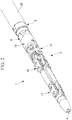
Fig. 1} Fig. 1 is a partial perspective view illustrating a medical manipulator according to an embodiment of the present invention. - {
Fig. 2} Fig. 2 is a partial perspective view illustrating a state where a joint cover of the medical manipulator inFig. 1 is removed. - {
Fig. 3} Fig. 3 is a partial longitudinal sectional view illustrating a connected state of a joint section, a connection member, and an elongated section of the medical manipulator inFig. 1 . - {
Fig. 4} Fig. 4 is a partial perspective view illustrating a disconnected state of the joint section, the connection member, and the elongated section of the medical manipulator inFig. 1 . - {
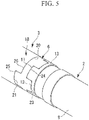
Fig. 5} Fig. 5 is a partial perspective view illustrating a combined state of the joint section, the connection member, and the elongated section inFig. 4 . - A medical manipulator 1 according to an embodiment of the present invention will be described below with reference to the drawings.
- As shown in
Figs. 1 and2 , the medical manipulator 1 according to this embodiment is to be inserted into the body of a patient through a channel provided in a flexible insertion section of, for example, an endoscope or an overtube and includes a flexibleelongated section 2 that is bendable in conformity to a winding channel, ajoint section 3 attached to the distal end of theelongated section 2, atreatment section 4 supported by the distal end of thejoint section 3, anelectric cable 5 for supplying electric power to thetreatment section 4, aconnection member 6 that connects theelongated section 2 and thejoint section 3, and acover 7 that covers thejoint section 3 and theelongated section 2. - As shown in
Fig. 3 , theelongated section 2 includes acoil tube 8, formed by winding a metallic wire rod into a shape of a tightly wound coil, and amulti-lumen tube 9 extending internally through thecoil tube 8. - The
multi-lumen tube 9 is composed of a flexible resin material, such as silicone resin, and has a plurality of through-holes 10 through which, for example, wires (not shown) for driving theelectric cable 5 and thejoint section 3 extend. - As shown in
Fig. 4 , a tubular protrusion-recess member 13 having a plurality of (four in the example in the drawing) protrusions (elongated-section-side protrusion-recess section) 11 and a plurality of recesses (elongated-section-side protrusion-recess section) 12 alternately arranged in the circumferential direction is fixed to the distal end of thecoil tube 8. - The
joint section 3 includes threejoints elongated section 2 and is formed by combining a plurality of metallic components. - The inside of the
joint section 3 is provided with a through-hole 17 through which theelectric cable 5 extends so that electric power can be supplied to thetreatment section 4 supported at the distal end thereof. - Furthermore, as shown in
Fig. 4 , abase member 18 disposed at the proximal end of thejoint section 3 includes acylindrical fitting section 19, and the outer peripheral surface of thefitting section 19 is provided with a plurality of (two in the example in the drawing) protrusions (joint-side protrusion-recess section) 20 and a plurality of recesses (joint-side protrusion-recess section) 21 extending in the axial direction and alternately arranged in the circumferential direction, similarly to the protrusion-recess member 13 attached to thecoil tube 8. - The
treatment section 4 is, for example, an electric scalpel having an electrode at the distal end thereof. - The
electric cable 5 is formed by covering a metallic electric wire with a sheath composed of an insulating material. - As shown in
Fig. 4 , theconnection member 6 is a cylindrical member and includes afitting section 22 that fits into the protrusion-recess member 13 provided at the distal end of theaforementioned coil tube 8. Moreover, as shown inFig. 5 , theconnection member 6 includes protrusions (elongated-section-side protrusion-recess section) 23 to be combined with therecesses 12 of the protrusion-recess member 13 and recesses (elongated-section-side protrusion-recess section) 24 to be combined with theprotrusions 11 of the protrusion-recess member 13 when thefitting section 22 is fitted onto the inside surface of the protrusion-recess member 13, and theprotrusions 23 and therecesses 24 are arranged in the circumferential direction. The shape of the protrusions and recesses at the proximal end of theconnection member 6 is substantially complementary to the shape of the protrusions and recesses of the protrusion-recess member 13. - The distal end of the
connection member 6 is provided with protrusions (joint-side protrusion-recess section) 25 to be combined with therecesses 21 of thebase member 18 and recesses (joint-side protrusion-recess section) 26 to be combined with theprotrusions 20 of thebase member 18 when thefitting section 19 of thebase member 18 of thejoint section 3 is fitted with theconnection member 6, and theprotrusions 25 and therecesses 26 are arranged in the circumferential direction. The shape of the protrusions and recesses at the distal end of theconnection member 6 is also substantially complementary to the shape of the protrusions and recesses of thebase member 18. - The
connection member 6 is composed of a rigid insulating material, such as PEEK, ceramic, or polyethylene. - When the
base member 18 of thejoint section 3, theconnection member 6, and the protrusion-recess member 13 of thecoil tube 8 are fitted to one another, therecesses protrusions Fig. 5 , so as not to move relative to one another in the circumferential direction. - Accordingly, torsional torque transmitted by the
coil tube 8 is transmitted to theconnection member 6 by the engagement between therecesses protrusions base member 18. - Since a wire for driving the
joint section 3 is disposed within thejoint section 3 and theelongated section 2 and a tensile force is applied to the wire for driving thejoint section 3, thebase member 18 of thejoint section 3, theconnection member 6, and the protrusion-recess member 13 of thecoil tube 8 do not move away from one another in the axial direction even if they are not locked to one another in the axial direction, whereby the fitted state is maintained. - As shown in
Fig. 1 , thecover 7 includes ajoint cover 27 that covers the outer surface of thejoint section 3 and an elongated-section cover 28 that covers the outer surface of theelongated section 2. - As shown in
Fig. 3 , thejoint cover 27 and the elongated-section cover 28 extend to positions where each of them partially covers theconnection member 6 and they are disposed such that the ends thereof face each other. - The
joint cover 27 is composed of silicone resin, fluororesin, or urethane resin and has a wall thickness of, for example, 0.2 mm. - The elongated-
section cover 28 is composed of urethane resin, FEP, or silicone resin and has a wall thickness of, for example, 0.2 mm. - The operation of the medical manipulator 1 according to this embodiment having the above-described configuration will be described below.
- In order to medically treat a treatment site inside the body of a patient by using the medical manipulator 1 according to this embodiment, the medical manipulator 1 is inserted through a channel provided in, for example, an endoscope or an overtube inserted in the body of the patient, starting from the
treatment section 4. Then, thetreatment section 4 protruding from the distal end of the channel is brought closer to the treatment site. - Subsequently, the position and orientation of the
treatment section 4 are adjusted by driving thejoint section 3. Moreover, by applying torsional torque about the longitudinal axis of theelongated section 2 at the proximal end of theelongated section 2, thejoint section 3 is rotated by the torsional torque transmitted by theelongated section 2, whereby the orientation of thetreatment section 4 about the longitudinal axis of theelongated section 2 can be adjusted. - Specifically, because the
elongated section 2 is formed of thecoil tube 8, torsional torque applied to the proximal end can be reliably transmitted to the distal end. Furthermore, the protrusion-recess member 13 fixed to the distal end of thecoil tube 8 is combined with theconnection member 6 and is engaged therewith in the circumferential direction. Moreover, theconnection member 6 and thebase member 18 are also combined with each other and are engaged with each other in the circumferential direction, so that the torsional torque transmitted by thecoil tube 8 is reliably transmitted to thejoint section 3 via theconnection member 6 and thebase member 18. - In the medical manipulator 1 according to this embodiment, the
electric cable 5 is routed by means of themulti-lumen tube 9 and the insulating material covering theelectric cable 5, which extend internally through thecoil tube 8 and thejoint section 3 along the entire length thereof, so that capacitor elements are formed between thecoil tube 8 and theelectric cable 5 and between thejoint section 3 and theelectric cable 5 when alternating current is applied. - In this case, since the
connection member 6 composed of an insulating material is disposed between thecoil tube 8 and thejoint section 3, exchanging of electric charge is not performed between theelongated section 2 and thejoint section 3. Therefore, the capacitor element in thejoint section 3 is small and independent from the capacitor element in theelongated section 2, and the capacitance in this case is reduced to a sufficiently small value. As a result, even when thejoint section 3 is moved to come into contact with tissue surrounding the treatment site, large electric charge is not accumulated since the capacitor element is minimized. This is advantageous in that leakage current can be sufficiently and effectively reduced or blocked by thejoint cover 27, which is extremely thin. - Specifically, since the
joint cover 27 is thin, the outer diameter of thejoint section 3 can be sufficiently reduced. Accordingly, this enables improved ease of insertion through the channel. Moreover, by reducing the thickness of thejoint cover 27, the movement of thejoint section 3 is prevented from being inhibited by thecover 7, which is advantageous in terms of improved ease of operation of thejoint section 3. - As an alternative to this embodiment in which the
joint section 3 is constituted of metallic components, thejoint section 3 may include components composed of an electrically conductive material and may be constituted of a torsional-torque transmittable member, such as a resinous component. - As an alternative to this embodiment in which torsional torque is transmitted from the
elongated section 2 by theconnection member 6 that insulates theelongated section 2 and thejoint section 3 from each other, the medical manipulator 1 may include an operating section (not shown) to which torsional torque is input, and thejoint section 3 may generate torsional torque on the basis of the input from the operating section. In this case, the operating section is, for example, a wire. By pushing and pulling the wire, torque may be generated in thejoint section 3 about the longitudinal axis of theelongated section 2. -
- 1 medical manipulator
- 2 elongated section
- 3 joint section
- 4 treatment section
- 5 electric cable
- 6 connection member
- 11, 20, 23, 25 protrusion (joint-side protrusion-recess section, elongated-section-side protrusion-recess section)
- 12, 21, 24, 26 recess (joint-side protrusion-recess section, elongated-section-side protrusion-recess section)
- 14, 15, 16 joint
- 27 joint cover
- 28 elongated-section cover
Claims (5)
- A medical manipulator comprising:a flexible elongated section that includes a component composed of an electrically conductive material and that is capable of transmitting torsional torque;a joint section that is disposed at a distal end of the elongated section and that has at least one joint and includes a component composed of an electrically conductive material;a treatment section that is attached to a distal end of the joint section and that medically treats tissue;a cylindrical connection member that is composed of an insulating material and that is disposed between the elongated section and the joint section to connect the elongated section and the joint section;an electric cable that extends internally through the elongated section, the connection member, and the joint section in a state where the electric cable is electrically insulated from the elongated section and the joint section and that supplies electric power to the treatment section; anda cover that is composed of an insulating material and that covers outer surfaces of the joint section and the elongated section.
- The medical manipulator according to Claim 1,
wherein the connection member connects the elongated section and the joint section such that torsional torque can be transmitted between the elongated section and the joint section. - The medical manipulator according to Claim 1 or 2,
wherein the joint section and the connection member individually have joint-side protrusion-recess sections that are fitted to each other in a detachable manner in a direction extending along an axis of the connection member and that engage with each other in a fitted state so that the joint section and the connection member do not relatively move in a circumferential direction. - The medical manipulator according to any one of Claims 1 to 3,
wherein the connection member and the elongated section individually have elongated-section-side protrusion-recess sections that are fitted to each other in a detachable manner in a direction extending along an axis of the connection member and that engage with each other in a fitted state so that the connection member and the elongated section do not relatively move in a circumferential direction. - The medical manipulator according to any one of Claims 1 to 4,
wherein the cover includes a joint cover that covers the joint section and an elongated section cover that covers the elongated section, and
wherein the joint cover and the long-section cover extend to a position where the covers partially cover the connection member.
Applications Claiming Priority (2)
| Application Number | Priority Date | Filing Date | Title |
|---|---|---|---|
| US201562168987P | 2015-06-01 | 2015-06-01 | |
| PCT/JP2015/074792 WO2016194249A1 (en) | 2015-06-01 | 2015-08-31 | Medical manipulator |
Publications (2)
| Publication Number | Publication Date |
|---|---|
| EP3305229A1 true EP3305229A1 (en) | 2018-04-11 |
| EP3305229A4 EP3305229A4 (en) | 2019-02-20 |
Family
ID=57440302
Family Applications (5)
| Application Number | Title | Priority Date | Filing Date |
|---|---|---|---|
| EP15894281.3A Withdrawn EP3305229A4 (en) | 2015-06-01 | 2015-08-31 | MEDICAL MANIPULATOR |
| EP15894282.1A Withdrawn EP3305162A4 (en) | 2015-06-01 | 2015-10-02 | MEDICAL MANIPULATOR SYSTEM |
| EP15894294.6A Withdrawn EP3305237A4 (en) | 2015-06-01 | 2015-11-16 | MANIPULATOR SYSTEM FOR MEDICAL USE |
| EP15894295.3A Withdrawn EP3305238A4 (en) | 2015-06-01 | 2015-11-19 | DRAPED UNIT |
| EP16802987.4A Withdrawn EP3305358A4 (en) | 2015-06-01 | 2016-05-09 | MEDICAL TUBE |
Family Applications After (4)
| Application Number | Title | Priority Date | Filing Date |
|---|---|---|---|
| EP15894282.1A Withdrawn EP3305162A4 (en) | 2015-06-01 | 2015-10-02 | MEDICAL MANIPULATOR SYSTEM |
| EP15894294.6A Withdrawn EP3305237A4 (en) | 2015-06-01 | 2015-11-16 | MANIPULATOR SYSTEM FOR MEDICAL USE |
| EP15894295.3A Withdrawn EP3305238A4 (en) | 2015-06-01 | 2015-11-19 | DRAPED UNIT |
| EP16802987.4A Withdrawn EP3305358A4 (en) | 2015-06-01 | 2016-05-09 | MEDICAL TUBE |
Country Status (5)
| Country | Link |
|---|---|
| US (5) | US10117716B2 (en) |
| EP (5) | EP3305229A4 (en) |
| JP (5) | JP6157792B2 (en) |
| CN (5) | CN107249491A (en) |
| WO (5) | WO2016194249A1 (en) |
Families Citing this family (75)
| Publication number | Priority date | Publication date | Assignee | Title |
|---|---|---|---|---|
| US8414505B1 (en) | 2001-02-15 | 2013-04-09 | Hansen Medical, Inc. | Catheter driver system |
| EP1432724A4 (en) | 2002-02-20 | 2006-02-01 | Sirna Therapeutics Inc | INTERFERENCE MEDIATION INHIBITION OF GENE RNA FROM MAP KINASE |
| US20120191107A1 (en) | 2010-09-17 | 2012-07-26 | Tanner Neal A | Systems and methods for positioning an elongate member inside a body |
| US20130317519A1 (en) | 2012-05-25 | 2013-11-28 | Hansen Medical, Inc. | Low friction instrument driver interface for robotic systems |
| US9668814B2 (en) | 2013-03-07 | 2017-06-06 | Hansen Medical, Inc. | Infinitely rotatable tool with finite rotating drive shafts |
| US20140277334A1 (en) | 2013-03-14 | 2014-09-18 | Hansen Medical, Inc. | Active drives for robotic catheter manipulators |
| US9173713B2 (en) | 2013-03-14 | 2015-11-03 | Hansen Medical, Inc. | Torque-based catheter articulation |
| US9498601B2 (en) | 2013-03-14 | 2016-11-22 | Hansen Medical, Inc. | Catheter tension sensing |
| US11213363B2 (en) | 2013-03-14 | 2022-01-04 | Auris Health, Inc. | Catheter tension sensing |
| US9326822B2 (en) | 2013-03-14 | 2016-05-03 | Hansen Medical, Inc. | Active drives for robotic catheter manipulators |
| US20140276936A1 (en) | 2013-03-15 | 2014-09-18 | Hansen Medical, Inc. | Active drive mechanism for simultaneous rotation and translation |
| US20140276647A1 (en) | 2013-03-15 | 2014-09-18 | Hansen Medical, Inc. | Vascular remote catheter manipulator |
| US9408669B2 (en) | 2013-03-15 | 2016-08-09 | Hansen Medical, Inc. | Active drive mechanism with finite range of motion |
| US9452018B2 (en) | 2013-03-15 | 2016-09-27 | Hansen Medical, Inc. | Rotational support for an elongate member |
| EP3689284B1 (en) | 2013-10-24 | 2025-02-26 | Auris Health, Inc. | System for robotic-assisted endolumenal surgery |
| US10046140B2 (en) | 2014-04-21 | 2018-08-14 | Hansen Medical, Inc. | Devices, systems, and methods for controlling active drive systems |
| US10569052B2 (en) | 2014-05-15 | 2020-02-25 | Auris Health, Inc. | Anti-buckling mechanisms for catheters |
| US9561083B2 (en) | 2014-07-01 | 2017-02-07 | Auris Surgical Robotics, Inc. | Articulating flexible endoscopic tool with roll capabilities |
| WO2016136306A1 (en) * | 2015-02-26 | 2016-09-01 | オリンパス株式会社 | Medical master-slave maniupulator system |
| CN113274140B (en) | 2015-09-09 | 2022-09-02 | 奥瑞斯健康公司 | Surgical covering |
| US9949749B2 (en) | 2015-10-30 | 2018-04-24 | Auris Surgical Robotics, Inc. | Object capture with a basket |
| US9955986B2 (en) | 2015-10-30 | 2018-05-01 | Auris Surgical Robotics, Inc. | Basket apparatus |
| US10639108B2 (en) | 2015-10-30 | 2020-05-05 | Auris Health, Inc. | Process for percutaneous operations |
| US10454347B2 (en) | 2016-04-29 | 2019-10-22 | Auris Health, Inc. | Compact height torque sensing articulation axis assembly |
| GB2552553B (en) | 2016-07-29 | 2022-03-16 | Cmr Surgical Ltd | Motion feedthrough |
| GB2552540B (en) * | 2016-07-29 | 2021-11-24 | Cmr Surgical Ltd | Interface structure |
| US11925431B2 (en) | 2016-07-29 | 2024-03-12 | Cmr Surgical Limited | Motion feedthrough |
| US11241559B2 (en) | 2016-08-29 | 2022-02-08 | Auris Health, Inc. | Active drive for guidewire manipulation |
| KR102555546B1 (en) | 2016-08-31 | 2023-07-19 | 아우리스 헬스, 인코포레이티드 | length-preserving surgical instruments |
| JP2020000263A (en) * | 2016-10-27 | 2020-01-09 | 株式会社カネカ | Catheter assembly body and stored article |
| JP6761482B2 (en) | 2016-12-28 | 2020-09-23 | オリンパス株式会社 | Medical systems, medical overtubes, and medical device adapters |
| US10244926B2 (en) | 2016-12-28 | 2019-04-02 | Auris Health, Inc. | Detecting endolumenal buckling of flexible instruments |
| US10543048B2 (en) | 2016-12-28 | 2020-01-28 | Auris Health, Inc. | Flexible instrument insertion using an adaptive insertion force threshold |
| CN110582246A (en) * | 2017-04-28 | 2019-12-17 | 奥林巴斯株式会社 | packaging |
| JP6631974B2 (en) * | 2017-05-16 | 2020-01-15 | リバーフィールド株式会社 | Power transmission adapter and medical manipulator system |
| US11026758B2 (en) | 2017-06-28 | 2021-06-08 | Auris Health, Inc. | Medical robotics systems implementing axis constraints during actuation of one or more motorized joints |
| CN107928790B (en) * | 2017-12-01 | 2020-05-05 | 微创(上海)医疗机器人有限公司 | Snake-shaped surgical instrument |
| MX2020006069A (en) | 2017-12-11 | 2020-11-06 | Auris Health Inc | Systems and methods for instrument based insertion architectures. |
| WO2019118767A1 (en) | 2017-12-14 | 2019-06-20 | Auris Health, Inc. | System and method for estimating instrument location |
| WO2019130984A1 (en) * | 2017-12-28 | 2019-07-04 | 株式会社メディカロイド | Surgical instrument, attached device, medical treatment tool, surgical robot, and remote surgery system |
| JP7463277B2 (en) | 2018-01-17 | 2024-04-08 | オーリス ヘルス インコーポレイテッド | Surgical robotic system having improved robotic arm |
| US10820954B2 (en) | 2018-06-27 | 2020-11-03 | Auris Health, Inc. | Alignment and attachment systems for medical instruments |
| US10820947B2 (en) | 2018-09-28 | 2020-11-03 | Auris Health, Inc. | Devices, systems, and methods for manually and robotically driving medical instruments |
| US20200100811A1 (en) * | 2018-10-02 | 2020-04-02 | Covidien Lp | Multi lumen access device |
| US12350450B2 (en) | 2018-10-31 | 2025-07-08 | Anchor Balloon, Llc | System and method for controlled delivery of medical devices into patient bodies |
| US10980653B2 (en) * | 2018-10-31 | 2021-04-20 | Anchor Balloon, Llc | System and method for controlled delivery of medical devices into patient bodies |
| WO2020197671A1 (en) | 2019-03-22 | 2020-10-01 | Auris Health, Inc. | Systems and methods for aligning inputs on medical instruments |
| KR102935983B1 (en) * | 2019-04-08 | 2026-03-10 | 아우리스 헬스, 인코포레이티드 | Systems, methods, and workflows for concurrent procedures |
| CN114051403B (en) | 2019-06-28 | 2026-03-17 | 奥瑞斯健康公司 | Patient guide for robotic systems |
| US11896330B2 (en) | 2019-08-15 | 2024-02-13 | Auris Health, Inc. | Robotic medical system having multiple medical instruments |
| GB2586998B (en) * | 2019-09-11 | 2022-07-13 | Prec Robotics Limited | A driver module |
| US11941629B2 (en) | 2019-09-27 | 2024-03-26 | Amazon Technologies, Inc. | Electronic device for automated user identification |
| US11737845B2 (en) | 2019-09-30 | 2023-08-29 | Auris Inc. | Medical instrument with a capstan |
| EP4064954A4 (en) | 2019-11-28 | 2024-02-14 | Microbot Medical Ltd. | Robotic manipulation of a surgical tool handle |
| CN114901188B (en) | 2019-12-31 | 2026-02-17 | 奥瑞斯健康公司 | Dynamic pulley system |
| KR20220123269A (en) | 2019-12-31 | 2022-09-06 | 아우리스 헬스, 인코포레이티드 | Advanced basket drive mode |
| JP6723595B1 (en) | 2020-02-18 | 2020-07-15 | リバーフィールド株式会社 | Drape unit |
| EP4122417B1 (en) * | 2020-04-17 | 2024-04-24 | RIVERFIELD Inc. | Floating drive mechanism for medical robot and medical robot |
| CN111513853B (en) * | 2020-05-11 | 2021-10-01 | 绍兴梅奥心磁医疗科技有限公司 | Catheter manipulation devices and systems |
| EP4167892A4 (en) | 2020-06-19 | 2024-10-30 | Remedy Robotics, Inc. | SYSTEMS AND METHODS FOR GUIDING INTRALUMINAL DEVICES WITHIN THE VASCULAR SYSTEM |
| US11270102B2 (en) * | 2020-06-29 | 2022-03-08 | Amazon Technologies, Inc. | Electronic device for automated user identification |
| CN112168354B (en) * | 2020-10-14 | 2021-07-16 | 北京科迈启元科技有限公司 | Waterproof and lightweight surgical robot actuator and surgical robot system |
| EP4272682A4 (en) * | 2021-02-01 | 2024-06-05 | Wuhan United Imaging Healthcare Surgical Technology Co., Ltd. | Master manipulator manipulation device for robot |
| WO2022161497A1 (en) | 2021-02-01 | 2022-08-04 | 武汉联影智融医疗科技有限公司 | Master hand control apparatus for use in robot and robot |
| JP7613951B2 (en) * | 2021-03-02 | 2025-01-15 | 株式会社カネカ | catheter |
| CN113211403A (en) * | 2021-04-19 | 2021-08-06 | 中国南方电网有限责任公司超高压输电公司贵阳局 | Intelligent dismounting method for high-voltage bushing in direct-current valve hall |
| US11707332B2 (en) | 2021-07-01 | 2023-07-25 | Remedy Robotics, Inc. | Image space control for endovascular tools |
| US12121307B2 (en) | 2021-07-01 | 2024-10-22 | Remedy Robotics, Inc. | Vision-based position and orientation determination for endovascular tools |
| CA3222522A1 (en) | 2021-07-01 | 2023-01-05 | David James Bell | Vision-based position and orientation determination for endovascular tools |
| US11903669B2 (en) * | 2021-07-30 | 2024-02-20 | Corindus, Inc | Sterile drape for robotic drive |
| CN113995517B (en) * | 2021-10-09 | 2026-01-06 | 深圳市精锋医疗科技股份有限公司 | Sheaths, surgical instruments, operating equipment, and surgical robots |
| WO2023157051A1 (en) * | 2022-02-15 | 2023-08-24 | リバーフィールド株式会社 | Columnar component |
| KR102860008B1 (en) | 2023-03-28 | 2025-09-16 | 한국기계연구원 | Manipulator with separated driving part |
| JP2025059427A (en) * | 2023-09-29 | 2025-04-10 | テルモ株式会社 | Medical Devices |
| CN118892297B (en) * | 2024-10-09 | 2025-03-21 | 湖南省华芯医疗器械有限公司 | Active bending section, insertion portion and endoscope |
Family Cites Families (58)
| Publication number | Priority date | Publication date | Assignee | Title |
|---|---|---|---|---|
| JPS6272091U (en) * | 1985-10-24 | 1987-05-08 | ||
| JP3181331B2 (en) * | 1991-10-04 | 2001-07-03 | 株式会社町田製作所 | Endoscope |
| JPH0695893A (en) * | 1992-09-16 | 1994-04-08 | Matsushita Electric Ind Co Ltd | Interrupt processing device |
| JP3429536B2 (en) * | 1993-09-30 | 2003-07-22 | オリンパス光学工業株式会社 | Endoscope sheath |
| US5681322A (en) * | 1994-11-14 | 1997-10-28 | Meadox Medicals, Inc. | Gas sterilizable intraluminal delivery system |
| US5855583A (en) * | 1996-02-20 | 1999-01-05 | Computer Motion, Inc. | Method and apparatus for performing minimally invasive cardiac procedures |
| US6331181B1 (en) | 1998-12-08 | 2001-12-18 | Intuitive Surgical, Inc. | Surgical robotic tools, data architecture, and use |
| US7727244B2 (en) | 1997-11-21 | 2010-06-01 | Intuitive Surgical Operation, Inc. | Sterile surgical drape |
| US6132368A (en) * | 1996-12-12 | 2000-10-17 | Intuitive Surgical, Inc. | Multi-component telepresence system and method |
| JP3776557B2 (en) * | 1997-04-10 | 2006-05-17 | オリンパス株式会社 | Endoscope |
| DE19940689A1 (en) * | 1999-08-27 | 2001-04-05 | Storz Karl Gmbh & Co Kg | Bipolar medical instrument |
| US20060178556A1 (en) * | 2001-06-29 | 2006-08-10 | Intuitive Surgical, Inc. | Articulate and swapable endoscope for a surgical robot |
| JP4420593B2 (en) | 2002-07-29 | 2010-02-24 | Hoya株式会社 | Bipolar high-frequency treatment instrument for endoscope |
| JP4286571B2 (en) * | 2003-03-31 | 2009-07-01 | 独立行政法人科学技術振興機構 | Surgical device |
| JP3783011B2 (en) | 2003-10-02 | 2006-06-07 | 株式会社日立製作所 | Operation input device, remote operation system, and remote operation method |
| US20050096502A1 (en) * | 2003-10-29 | 2005-05-05 | Khalili Theodore M. | Robotic surgical device |
| JP3873285B2 (en) | 2003-12-24 | 2007-01-24 | 有限会社エスアールジェイ | Endoscope device |
| US20050154439A1 (en) * | 2004-01-08 | 2005-07-14 | Gunderson Richard C. | Medical device delivery systems |
| JP4755638B2 (en) * | 2004-03-05 | 2011-08-24 | ハンセン メディカル,インク. | Robotic guide catheter system |
| ES2552252T3 (en) * | 2004-03-23 | 2015-11-26 | Boston Scientific Limited | Live View System |
| JP4652713B2 (en) | 2004-04-02 | 2011-03-16 | オリンパス株式会社 | Endoscopic treatment device |
| JP2006334695A (en) * | 2005-05-31 | 2006-12-14 | Kyoto Univ | Remote control device |
| WO2007070693A2 (en) * | 2005-12-14 | 2007-06-21 | Hansen Medical, Inc. | Robotic cathether system and methods |
| JP5043414B2 (en) | 2005-12-20 | 2012-10-10 | インテュイティブ サージカル インコーポレイテッド | Aseptic surgical adapter |
| US8225794B2 (en) | 2006-01-13 | 2012-07-24 | Olympus Medical Systems Corp. | Overtube |
| JP2007307289A (en) * | 2006-05-22 | 2007-11-29 | Fujinon Corp | Ultrasonic endoscope apparatus |
| JP2008114339A (en) | 2006-11-06 | 2008-05-22 | Terumo Corp | manipulator |
| US8715270B2 (en) | 2006-12-01 | 2014-05-06 | Boston Scientific Scimed, Inc. | Multi-part instrument systems and methods |
| JP4398479B2 (en) * | 2007-03-02 | 2010-01-13 | オリンパスメディカルシステムズ株式会社 | Endoscope device |
| CA2684459C (en) * | 2007-04-16 | 2016-10-04 | Neuroarm Surgical Ltd. | Methods, devices, and systems for non-mechanically restricting and/or programming movement of a tool of a manipulator along a single axis |
| JP2008278968A (en) | 2007-05-08 | 2008-11-20 | Fujinon Corp | Insertion assisting tool for endoscope |
| US9084623B2 (en) | 2009-08-15 | 2015-07-21 | Intuitive Surgical Operations, Inc. | Controller assisted reconfiguration of an articulated instrument during movement into and out of an entry guide |
| US8105230B2 (en) | 2007-07-09 | 2012-01-31 | Olympus Medical Systems Corp. | Medical system |
| JP5011060B2 (en) * | 2007-10-22 | 2012-08-29 | オリンパスメディカルシステムズ株式会社 | Medical equipment |
| CA2711593C (en) | 2008-01-14 | 2017-04-25 | Boston Scientific Scimed, Inc. | Catheter with stable position during guide wire exchange |
| US7886743B2 (en) | 2008-03-31 | 2011-02-15 | Intuitive Surgical Operations, Inc. | Sterile drape interface for robotic surgical instrument |
| JP4950928B2 (en) * | 2008-03-31 | 2012-06-13 | 富士フイルム株式会社 | Ultrasound endoscope device |
| JP5336760B2 (en) | 2008-05-01 | 2013-11-06 | オリンパスメディカルシステムズ株式会社 | Endoscope system |
| US20090281378A1 (en) | 2008-05-09 | 2009-11-12 | Kazuo Banju | Medical system |
| JP2010035768A (en) * | 2008-08-04 | 2010-02-18 | Olympus Medical Systems Corp | Active drive type medical apparatus |
| US9339342B2 (en) * | 2008-09-30 | 2016-05-17 | Intuitive Surgical Operations, Inc. | Instrument interface |
| US8720448B2 (en) * | 2008-11-07 | 2014-05-13 | Hansen Medical, Inc. | Sterile interface apparatus |
| EP2324789B1 (en) * | 2008-11-14 | 2017-06-21 | Olympus Corporation | Medical system |
| US20100331856A1 (en) * | 2008-12-12 | 2010-12-30 | Hansen Medical Inc. | Multiple flexible and steerable elongate instruments for minimally invasive operations |
| US8120301B2 (en) | 2009-03-09 | 2012-02-21 | Intuitive Surgical Operations, Inc. | Ergonomic surgeon control console in robotic surgical systems |
| US20100298646A1 (en) * | 2009-05-19 | 2010-11-25 | Tyco Healthcare Group Lp | Flexible access assembly with reinforced lumen |
| WO2011037394A2 (en) * | 2009-09-23 | 2011-03-31 | 주식회사 이턴 | Sterile adapter, fastening structure of wheels, and fastening structure of surgical instrument |
| JP2011072574A (en) * | 2009-09-30 | 2011-04-14 | Terumo Corp | Medical manipulator |
| JP2011072570A (en) * | 2009-09-30 | 2011-04-14 | Terumo Corp | Medical manipulator |
| JP5624420B2 (en) * | 2010-09-29 | 2014-11-12 | カール シュトルツ ゲゼルシャフト ミット ベシュレンクテル ハフツング ウント コンパニー コマンディートゲゼルシャフト | Insulating cover and surgical instrument |
| JP5701140B2 (en) * | 2011-04-21 | 2015-04-15 | キヤノン株式会社 | Stereoscopic endoscope device |
| JP5931497B2 (en) * | 2011-08-04 | 2016-06-08 | オリンパス株式会社 | Surgery support apparatus and assembly method thereof |
| CN104622581B (en) | 2012-07-03 | 2018-02-02 | 库卡实验仪器有限公司 | The driver group and operating theater instruments of operating theater instruments group, the particularly operating theater instruments of robot guiding |
| JP5617056B2 (en) | 2012-08-31 | 2014-10-29 | オリンパスメディカルシステムズ株式会社 | Insert body, insertion device, rotation unit, rotational force transmission unit |
| WO2014106047A1 (en) | 2012-12-28 | 2014-07-03 | Porex Corporation | Sintered porous polymeric caps and vents for components of medical devices |
| JP6084296B2 (en) * | 2013-02-25 | 2017-02-22 | オリンパス株式会社 | Medical system |
| JP6242101B2 (en) * | 2013-07-26 | 2017-12-06 | オリンパス株式会社 | Medical device and system |
| JP6674377B2 (en) | 2013-08-15 | 2020-04-01 | インテュイティブ サージカル オペレーションズ, インコーポレイテッド | Apparatus with proximal and distal driven discs |
-
2015
- 2015-08-31 JP JP2017517392A patent/JP6157792B2/en active Active
- 2015-08-31 WO PCT/JP2015/074792 patent/WO2016194249A1/en not_active Ceased
- 2015-08-31 EP EP15894281.3A patent/EP3305229A4/en not_active Withdrawn
- 2015-08-31 CN CN201580076955.8A patent/CN107249491A/en active Pending
- 2015-10-02 JP JP2016537579A patent/JP6010266B1/en active Active
- 2015-10-02 EP EP15894282.1A patent/EP3305162A4/en not_active Withdrawn
- 2015-10-02 CN CN201580030682.3A patent/CN106455928B/en active Active
- 2015-10-02 WO PCT/JP2015/078063 patent/WO2016194250A1/en not_active Ceased
- 2015-11-16 CN CN201580075580.3A patent/CN107205789B/en active Active
- 2015-11-16 WO PCT/JP2015/082118 patent/WO2016194262A1/en not_active Ceased
- 2015-11-16 JP JP2017510696A patent/JP6147460B2/en active Active
- 2015-11-16 EP EP15894294.6A patent/EP3305237A4/en not_active Withdrawn
- 2015-11-19 WO PCT/JP2015/082622 patent/WO2016194263A1/en not_active Ceased
- 2015-11-19 EP EP15894295.3A patent/EP3305238A4/en not_active Withdrawn
- 2015-11-19 JP JP2017502902A patent/JP6138396B2/en active Active
- 2015-11-19 CN CN201580073366.4A patent/CN107106250A/en active Pending
-
2016
- 2016-05-09 CN CN201680031398.2A patent/CN107614047A/en active Pending
- 2016-05-09 JP JP2017508586A patent/JP6242538B2/en active Active
- 2016-05-09 WO PCT/JP2016/063786 patent/WO2016194550A1/en not_active Ceased
- 2016-05-09 EP EP16802987.4A patent/EP3305358A4/en not_active Withdrawn
- 2016-12-12 US US15/375,374 patent/US10117716B2/en active Active
-
2017
- 2017-11-06 US US15/804,025 patent/US10335243B2/en active Active
- 2017-11-06 US US15/804,068 patent/US10201394B2/en active Active
- 2017-11-21 US US15/819,045 patent/US20180071041A1/en not_active Abandoned
- 2017-11-28 US US15/824,481 patent/US10314663B2/en active Active
Also Published As
Similar Documents
| Publication | Publication Date | Title |
|---|---|---|
| EP3305229A1 (en) | Medical manipulator | |
| US20160128766A1 (en) | Medical instrument and medical system | |
| CN103705299B (en) | Electro-thermal device | |
| EP2554131A1 (en) | Treatment tool for endoscope | |
| CN114615918B (en) | Cables and wiring in the robotic arms of surgical equipment | |
| US20170007346A1 (en) | Treatment device and surgical system | |
| JP2021531837A5 (en) | ||
| WO2016166828A1 (en) | Operating part for bendable treatment tool | |
| JP6177095B2 (en) | Treatment instrument and medical system | |
| CN109068942A (en) | medical overtube | |
| US20220151686A1 (en) | High-frequency forceps | |
| US20170181609A1 (en) | Endoscope | |
| KR100896750B1 (en) | Medical device for insertion of living body | |
| JP6347851B2 (en) | Endoscope energy treatment tool and endoscope system | |
| JP7114635B2 (en) | CATHETER HANDLE AND CATHETER WITH THE SAME | |
| US20140330272A1 (en) | Application probe | |
| EP3056159B1 (en) | Medical device | |
| CN113543941B (en) | Surgical tool for surgical auxiliary robot | |
| CN110772330B (en) | Surgical instruments | |
| US12544170B2 (en) | Medical manipulator | |
| EP4717221A1 (en) | Medical instrument | |
| JP2023548077A (en) | endoscope cap | |
| CN105934189B (en) | Disposal devices and medical systems | |
| JP2022107587A (en) | Guidewire with heavy insulation for use during irreversible electroporation (ire) | |
| KR20160056726A (en) | Endoscope tube |
Legal Events
| Date | Code | Title | Description |
|---|---|---|---|
| STAA | Information on the status of an ep patent application or granted ep patent |
Free format text: STATUS: THE INTERNATIONAL PUBLICATION HAS BEEN MADE |
|
| PUAI | Public reference made under article 153(3) epc to a published international application that has entered the european phase |
Free format text: ORIGINAL CODE: 0009012 |
|
| STAA | Information on the status of an ep patent application or granted ep patent |
Free format text: STATUS: REQUEST FOR EXAMINATION WAS MADE |
|
| 17P | Request for examination filed |
Effective date: 20171221 |
|
| AK | Designated contracting states |
Kind code of ref document: A1 Designated state(s): AL AT BE BG CH CY CZ DE DK EE ES FI FR GB GR HR HU IE IS IT LI LT LU LV MC MK MT NL NO PL PT RO RS SE SI SK SM TR |
|
| AX | Request for extension of the european patent |
Extension state: BA ME |
|
| DAV | Request for validation of the european patent (deleted) | ||
| DAX | Request for extension of the european patent (deleted) | ||
| A4 | Supplementary search report drawn up and despatched |
Effective date: 20190117 |
|
| RIC1 | Information provided on ipc code assigned before grant |
Ipc: A61L 2/20 20060101ALI20190111BHEP Ipc: A61B 17/34 20060101ALI20190111BHEP Ipc: A61B 18/14 20060101ALI20190111BHEP Ipc: A61B 34/30 20160101ALI20190111BHEP Ipc: A61M 25/00 20060101AFI20190111BHEP Ipc: A61B 17/00 20060101ALI20190111BHEP Ipc: A61B 18/00 20060101ALI20190111BHEP Ipc: A61B 90/00 20160101ALI20190111BHEP Ipc: A61B 17/29 20060101ALI20190111BHEP |
|
| STAA | Information on the status of an ep patent application or granted ep patent |
Free format text: STATUS: THE APPLICATION HAS BEEN WITHDRAWN |
|
| 18W | Application withdrawn |
Effective date: 20190409 |