JP7114635B2 - CATHETER HANDLE AND CATHETER WITH THE SAME - Google Patents
CATHETER HANDLE AND CATHETER WITH THE SAME Download PDFInfo
- Publication number
- JP7114635B2 JP7114635B2 JP2019568858A JP2019568858A JP7114635B2 JP 7114635 B2 JP7114635 B2 JP 7114635B2 JP 2019568858 A JP2019568858 A JP 2019568858A JP 2019568858 A JP2019568858 A JP 2019568858A JP 7114635 B2 JP7114635 B2 JP 7114635B2
- Authority
- JP
- Japan
- Prior art keywords
- rotating member
- handle
- wire
- catheter
- space
- Prior art date
- Legal status (The legal status is an assumption and is not a legal conclusion. Google has not performed a legal analysis and makes no representation as to the accuracy of the status listed.)
- Active
Links
- 238000005192 partition Methods 0.000 claims description 50
- 239000004020 conductor Substances 0.000 claims description 25
- 238000003780 insertion Methods 0.000 claims description 12
- 230000037431 insertion Effects 0.000 claims description 12
- 238000013459 approach Methods 0.000 claims description 6
- 238000000638 solvent extraction Methods 0.000 claims description 5
- WABPQHHGFIMREM-UHFFFAOYSA-N lead(0) Chemical compound [Pb] WABPQHHGFIMREM-UHFFFAOYSA-N 0.000 description 10
- 229920003002 synthetic resin Polymers 0.000 description 9
- 239000000057 synthetic resin Substances 0.000 description 9
- -1 polyethylene Polymers 0.000 description 8
- 229920005989 resin Polymers 0.000 description 6
- 239000011347 resin Substances 0.000 description 6
- 229910045601 alloy Inorganic materials 0.000 description 5
- 239000000956 alloy Substances 0.000 description 5
- 229910052751 metal Inorganic materials 0.000 description 5
- 239000002184 metal Substances 0.000 description 5
- XEEYBQQBJWHFJM-UHFFFAOYSA-N Iron Chemical compound [Fe] XEEYBQQBJWHFJM-UHFFFAOYSA-N 0.000 description 4
- BASFCYQUMIYNBI-UHFFFAOYSA-N platinum Chemical compound [Pt] BASFCYQUMIYNBI-UHFFFAOYSA-N 0.000 description 4
- YCKRFDGAMUMZLT-UHFFFAOYSA-N Fluorine atom Chemical compound [F] YCKRFDGAMUMZLT-UHFFFAOYSA-N 0.000 description 3
- 239000004677 Nylon Substances 0.000 description 3
- 239000004698 Polyethylene Substances 0.000 description 3
- 239000004743 Polypropylene Substances 0.000 description 3
- HZEWFHLRYVTOIW-UHFFFAOYSA-N [Ti].[Ni] Chemical compound [Ti].[Ni] HZEWFHLRYVTOIW-UHFFFAOYSA-N 0.000 description 3
- 238000005452 bending Methods 0.000 description 3
- 210000004204 blood vessel Anatomy 0.000 description 3
- 229920001971 elastomer Polymers 0.000 description 3
- 229920000840 ethylene tetrafluoroethylene copolymer Polymers 0.000 description 3
- 239000011737 fluorine Substances 0.000 description 3
- 229910052731 fluorine Inorganic materials 0.000 description 3
- 229910001000 nickel titanium Inorganic materials 0.000 description 3
- 229920001778 nylon Polymers 0.000 description 3
- 229920011301 perfluoro alkoxyl alkane Polymers 0.000 description 3
- 229920006122 polyamide resin Polymers 0.000 description 3
- 229920000573 polyethylene Polymers 0.000 description 3
- 229920005672 polyolefin resin Polymers 0.000 description 3
- 229920001155 polypropylene Polymers 0.000 description 3
- 229920001343 polytetrafluoroethylene Polymers 0.000 description 3
- 239000004810 polytetrafluoroethylene Substances 0.000 description 3
- 238000003825 pressing Methods 0.000 description 3
- 229910001220 stainless steel Inorganic materials 0.000 description 3
- 229910000975 Carbon steel Inorganic materials 0.000 description 2
- RYGMFSIKBFXOCR-UHFFFAOYSA-N Copper Chemical compound [Cu] RYGMFSIKBFXOCR-UHFFFAOYSA-N 0.000 description 2
- 239000004696 Poly ether ether ketone Substances 0.000 description 2
- 239000004721 Polyphenylene oxide Substances 0.000 description 2
- PPBRXRYQALVLMV-UHFFFAOYSA-N Styrene Chemical compound C=CC1=CC=CC=C1 PPBRXRYQALVLMV-UHFFFAOYSA-N 0.000 description 2
- 206010003119 arrhythmia Diseases 0.000 description 2
- 230000006793 arrhythmia Effects 0.000 description 2
- 125000003118 aryl group Chemical group 0.000 description 2
- JUPQTSLXMOCDHR-UHFFFAOYSA-N benzene-1,4-diol;bis(4-fluorophenyl)methanone Chemical compound OC1=CC=C(O)C=C1.C1=CC(F)=CC=C1C(=O)C1=CC=C(F)C=C1 JUPQTSLXMOCDHR-UHFFFAOYSA-N 0.000 description 2
- 239000010962 carbon steel Substances 0.000 description 2
- 239000011162 core material Substances 0.000 description 2
- 239000000806 elastomer Substances 0.000 description 2
- 230000012447 hatching Effects 0.000 description 2
- 239000011810 insulating material Substances 0.000 description 2
- 229910052742 iron Inorganic materials 0.000 description 2
- 239000007769 metal material Substances 0.000 description 2
- 238000000034 method Methods 0.000 description 2
- 229920009441 perflouroethylene propylene Polymers 0.000 description 2
- 230000002093 peripheral effect Effects 0.000 description 2
- 229910052697 platinum Inorganic materials 0.000 description 2
- 229920001225 polyester resin Polymers 0.000 description 2
- 239000004645 polyester resin Substances 0.000 description 2
- 229920000570 polyether Polymers 0.000 description 2
- 229920002530 polyetherether ketone Polymers 0.000 description 2
- 229920001721 polyimide Polymers 0.000 description 2
- 239000009719 polyimide resin Substances 0.000 description 2
- 229920000346 polystyrene-polyisoprene block-polystyrene Polymers 0.000 description 2
- 239000010935 stainless steel Substances 0.000 description 2
- 229920006132 styrene block copolymer Polymers 0.000 description 2
- 229920001935 styrene-ethylene-butadiene-styrene Polymers 0.000 description 2
- 244000043261 Hevea brasiliensis Species 0.000 description 1
- 229920000459 Nitrile rubber Polymers 0.000 description 1
- BQCADISMDOOEFD-UHFFFAOYSA-N Silver Chemical compound [Ag] BQCADISMDOOEFD-UHFFFAOYSA-N 0.000 description 1
- 238000010317 ablation therapy Methods 0.000 description 1
- 239000000853 adhesive Substances 0.000 description 1
- 230000001070 adhesive effect Effects 0.000 description 1
- 229910052782 aluminium Inorganic materials 0.000 description 1
- XAGFODPZIPBFFR-UHFFFAOYSA-N aluminium Chemical compound [Al] XAGFODPZIPBFFR-UHFFFAOYSA-N 0.000 description 1
- 229920001400 block copolymer Polymers 0.000 description 1
- MTAZNLWOLGHBHU-UHFFFAOYSA-N butadiene-styrene rubber Chemical compound C=CC=C.C=CC1=CC=CC=C1 MTAZNLWOLGHBHU-UHFFFAOYSA-N 0.000 description 1
- 239000011248 coating agent Substances 0.000 description 1
- 238000000576 coating method Methods 0.000 description 1
- 229910052802 copper Inorganic materials 0.000 description 1
- 239000010949 copper Substances 0.000 description 1
- 238000001514 detection method Methods 0.000 description 1
- 230000000694 effects Effects 0.000 description 1
- 229920001973 fluoroelastomer Polymers 0.000 description 1
- 210000001035 gastrointestinal tract Anatomy 0.000 description 1
- PCHJSUWPFVWCPO-UHFFFAOYSA-N gold Chemical compound [Au] PCHJSUWPFVWCPO-UHFFFAOYSA-N 0.000 description 1
- 229910052737 gold Inorganic materials 0.000 description 1
- 239000010931 gold Substances 0.000 description 1
- 238000003384 imaging method Methods 0.000 description 1
- 238000009413 insulation Methods 0.000 description 1
- 150000002576 ketones Chemical class 0.000 description 1
- 239000000463 material Substances 0.000 description 1
- 238000002844 melting Methods 0.000 description 1
- 230000008018 melting Effects 0.000 description 1
- 150000002739 metals Chemical class 0.000 description 1
- 238000012986 modification Methods 0.000 description 1
- 230000004048 modification Effects 0.000 description 1
- 229920003052 natural elastomer Polymers 0.000 description 1
- 229920001194 natural rubber Polymers 0.000 description 1
- 229920001643 poly(ether ketone) Polymers 0.000 description 1
- 229920002635 polyurethane Polymers 0.000 description 1
- 239000004814 polyurethane Substances 0.000 description 1
- 229920005749 polyurethane resin Polymers 0.000 description 1
- 239000004800 polyvinyl chloride Substances 0.000 description 1
- 229920000915 polyvinyl chloride Polymers 0.000 description 1
- 230000001105 regulatory effect Effects 0.000 description 1
- 238000000926 separation method Methods 0.000 description 1
- 229920002379 silicone rubber Polymers 0.000 description 1
- 239000004945 silicone rubber Substances 0.000 description 1
- 238000002560 therapeutic procedure Methods 0.000 description 1
- WFKWXMTUELFFGS-UHFFFAOYSA-N tungsten Chemical compound [W] WFKWXMTUELFFGS-UHFFFAOYSA-N 0.000 description 1
- 210000000626 ureter Anatomy 0.000 description 1
- 150000003673 urethanes Chemical class 0.000 description 1
- 238000003466 welding Methods 0.000 description 1
Images


Classifications
-
- A—HUMAN NECESSITIES
- A61—MEDICAL OR VETERINARY SCIENCE; HYGIENE
- A61M—DEVICES FOR INTRODUCING MEDIA INTO, OR ONTO, THE BODY; DEVICES FOR TRANSDUCING BODY MEDIA OR FOR TAKING MEDIA FROM THE BODY; DEVICES FOR PRODUCING OR ENDING SLEEP OR STUPOR
- A61M25/00—Catheters; Hollow probes
- A61M25/01—Introducing, guiding, advancing, emplacing or holding catheters
- A61M25/0105—Steering means as part of the catheter or advancing means; Markers for positioning
- A61M25/0133—Tip steering devices
- A61M25/0136—Handles therefor
-
- A—HUMAN NECESSITIES
- A61—MEDICAL OR VETERINARY SCIENCE; HYGIENE
- A61B—DIAGNOSIS; SURGERY; IDENTIFICATION
- A61B18/00—Surgical instruments, devices or methods for transferring non-mechanical forms of energy to or from the body
- A61B18/04—Surgical instruments, devices or methods for transferring non-mechanical forms of energy to or from the body by heating
- A61B18/12—Surgical instruments, devices or methods for transferring non-mechanical forms of energy to or from the body by heating by passing a current through the tissue to be heated, e.g. high-frequency current
- A61B18/14—Probes or electrodes therefor
- A61B18/1492—Probes or electrodes therefor having a flexible, catheter-like structure, e.g. for heart ablation
-
- A—HUMAN NECESSITIES
- A61—MEDICAL OR VETERINARY SCIENCE; HYGIENE
- A61M—DEVICES FOR INTRODUCING MEDIA INTO, OR ONTO, THE BODY; DEVICES FOR TRANSDUCING BODY MEDIA OR FOR TAKING MEDIA FROM THE BODY; DEVICES FOR PRODUCING OR ENDING SLEEP OR STUPOR
- A61M25/00—Catheters; Hollow probes
- A61M25/01—Introducing, guiding, advancing, emplacing or holding catheters
- A61M25/0105—Steering means as part of the catheter or advancing means; Markers for positioning
- A61M25/0133—Tip steering devices
- A61M25/0147—Tip steering devices with movable mechanical means, e.g. pull wires
-
- A—HUMAN NECESSITIES
- A61—MEDICAL OR VETERINARY SCIENCE; HYGIENE
- A61M—DEVICES FOR INTRODUCING MEDIA INTO, OR ONTO, THE BODY; DEVICES FOR TRANSDUCING BODY MEDIA OR FOR TAKING MEDIA FROM THE BODY; DEVICES FOR PRODUCING OR ENDING SLEEP OR STUPOR
- A61M25/00—Catheters; Hollow probes
- A61M25/01—Introducing, guiding, advancing, emplacing or holding catheters
- A61M25/09—Guide wires
-
- A—HUMAN NECESSITIES
- A61—MEDICAL OR VETERINARY SCIENCE; HYGIENE
- A61B—DIAGNOSIS; SURGERY; IDENTIFICATION
- A61B18/00—Surgical instruments, devices or methods for transferring non-mechanical forms of energy to or from the body
- A61B2018/00315—Surgical instruments, devices or methods for transferring non-mechanical forms of energy to or from the body for treatment of particular body parts
- A61B2018/00345—Vascular system
- A61B2018/00351—Heart
-
- A—HUMAN NECESSITIES
- A61—MEDICAL OR VETERINARY SCIENCE; HYGIENE
- A61B—DIAGNOSIS; SURGERY; IDENTIFICATION
- A61B18/00—Surgical instruments, devices or methods for transferring non-mechanical forms of energy to or from the body
- A61B2018/00571—Surgical instruments, devices or methods for transferring non-mechanical forms of energy to or from the body for achieving a particular surgical effect
- A61B2018/00577—Ablation
-
- A—HUMAN NECESSITIES
- A61—MEDICAL OR VETERINARY SCIENCE; HYGIENE
- A61B—DIAGNOSIS; SURGERY; IDENTIFICATION
- A61B18/00—Surgical instruments, devices or methods for transferring non-mechanical forms of energy to or from the body
- A61B2018/00636—Sensing and controlling the application of energy
- A61B2018/00773—Sensed parameters
- A61B2018/00839—Bioelectrical parameters, e.g. ECG, EEG
-
- A—HUMAN NECESSITIES
- A61—MEDICAL OR VETERINARY SCIENCE; HYGIENE
- A61B—DIAGNOSIS; SURGERY; IDENTIFICATION
- A61B18/00—Surgical instruments, devices or methods for transferring non-mechanical forms of energy to or from the body
- A61B2018/0091—Handpieces of the surgical instrument or device
-
- A—HUMAN NECESSITIES
- A61—MEDICAL OR VETERINARY SCIENCE; HYGIENE
- A61B—DIAGNOSIS; SURGERY; IDENTIFICATION
- A61B90/00—Instruments, implements or accessories specially adapted for surgery or diagnosis and not covered by any of the groups A61B1/00 - A61B50/00, e.g. for luxation treatment or for protecting wound edges
- A61B90/39—Markers, e.g. radio-opaque or breast lesions markers
- A61B2090/3966—Radiopaque markers visible in an X-ray image
-
- A—HUMAN NECESSITIES
- A61—MEDICAL OR VETERINARY SCIENCE; HYGIENE
- A61M—DEVICES FOR INTRODUCING MEDIA INTO, OR ONTO, THE BODY; DEVICES FOR TRANSDUCING BODY MEDIA OR FOR TAKING MEDIA FROM THE BODY; DEVICES FOR PRODUCING OR ENDING SLEEP OR STUPOR
- A61M2205/00—General characteristics of the apparatus
- A61M2205/02—General characteristics of the apparatus characterised by a particular materials
- A61M2205/0233—Conductive materials, e.g. antistatic coatings for spark prevention
Landscapes
- Health & Medical Sciences (AREA)
- Life Sciences & Earth Sciences (AREA)
- Engineering & Computer Science (AREA)
- Public Health (AREA)
- Veterinary Medicine (AREA)
- Biomedical Technology (AREA)
- Heart & Thoracic Surgery (AREA)
- Animal Behavior & Ethology (AREA)
- General Health & Medical Sciences (AREA)
- Hematology (AREA)
- Anesthesiology (AREA)
- Pulmonology (AREA)
- Biophysics (AREA)
- Surgery (AREA)
- Mechanical Engineering (AREA)
- Physics & Mathematics (AREA)
- Cardiology (AREA)
- Molecular Biology (AREA)
- Medical Informatics (AREA)
- Plasma & Fusion (AREA)
- Otolaryngology (AREA)
- Nuclear Medicine, Radiotherapy & Molecular Imaging (AREA)
- Media Introduction/Drainage Providing Device (AREA)
Description
本発明は、医療用カテーテルに用いられるカテーテル用ハンドルと、それを備えたカテーテルに関するものである。 TECHNICAL FIELD The present invention relates to a catheter handle used for a medical catheter and a catheter having the same.
医療用カテーテルは、通常、血管や消化管や尿管などの体内の管腔部に挿入するためのカテーテルチューブと、カテーテルチューブの近位側に設けられたハンドルとから構成されている。カテーテルには、手元のハンドルを操作してカテーテルチューブの遠位側を屈曲できるように構成されたものが知られており、このようなカテーテルは、カテーテルチューブの内腔に、カテーテルチューブの遠位側に固定されたワイヤが配され、ワイヤの近位側がハンドルに接続され、ハンドルを操作してワイヤを近位側に引いたり遠位側に押したりすることにより、カテーテルチューブの遠位側を屈曲できるようになっている。カテーテルチューブの遠位側に電極が設けられた電極付きカテーテルでは、カテーテルチューブの内腔にさらに導線が配されており、導線の近位側がハンドル内部まで延在して設けられている。なお、本明細書において、「電極付きカテーテル」を単に「電極カテーテル」と称する場合がある。 A medical catheter is usually composed of a catheter tube for insertion into a body lumen such as a blood vessel, digestive tract, or ureter, and a handle provided on the proximal side of the catheter tube. Catheters are known that are configured so that the distal side of the catheter tube can be bent by manipulating a handle at hand. A wire fixed to the side is placed, and the proximal side of the wire is connected to a handle that can be manipulated to pull the wire proximally or push it distally, thereby moving the distal side of the catheter tube. It is designed to be bendable. In electroded catheters in which electrodes are provided on the distal side of the catheter tube, a lead wire is further arranged in the lumen of the catheter tube, with the proximal side of the lead wire extending into the interior of the handle. In this specification, the "catheter with electrodes" may be simply referred to as "electrode catheter".
例えば特許文献1には、電極のリード線や各種チューブなどの長尺部品を内部に配することができるカテーテル用ハンドルが開示されており、当該ハンドルは、第1ハンドル部材と第2ハンドル部材とを組み合わせてなるハンドル本体と、前記第1ハンドル部材と前記第2ハンドル部材との間に配置され、前記ハンドル本体に対して、その長手方向に垂直な回転軸の周りを回転自在に装着され、前記カテーテルシャフトの先端を偏向させるための操作用ワイヤの基端が連結される回転板を有する回転操作部と、前記第1ハンドル部材に対して回転不能に固定されるとともに、前記回転板の回転軸に沿って当該回転板を貫通するよう配置され、その先端に雄ねじ部を有する調整ピンと、前記調整ピンの雄ねじ部と螺合する雌ねじ部を有し、前記第2ハンドル部材に対して回転可能に装着された調整摘みと、前記調整ピンの雄ねじ部と前記調整摘みの雌ねじ部との螺合深さに応じて前記回転板の操作力が変化するように、前記ハンドル本体と前記回転板との間に配置された弾性部材とを備えてなり;前記回転操作部は、互いに同径の円板状に形成された第1回転部材と第2回転部材とを組み合わせてなる前記回転板と、前記第1回転部材と前記第2回転部材との間に配置されるとともに、前記ハンドル本体に対して回転不能に固定された中間部材とを備えてなり;前記中間部材には、先端側から前記ハンドル本体の内部に挿入される長尺部品を、当該ハンドル本体の長手方向の中心軸に沿って延在させるための案内路と、前記回転板の外周形状に合致する形状を有する、前記回転操作部の外周壁とが一体的に形成され;前記調整ピンには、前記中心軸に沿って延在する長尺部品を挿通可能な貫通孔が形成されている(特許文献1の請求項1)。特許文献1にはまた、ハンドル本体と、このハンドル本体を構成する第1ハンドル部材と第2ハンドル部材との間に配置された回転板とを有するカテーテル用ハンドルにおいて、第1ハンドル部材と回転板の間に長尺部品を配置した態様も開示されている(特許文献1の段落0003、0008)。
For example,
特許文献1に開示されたカテーテル用ハンドルでは、導線などの長尺部品が回転板と厚み方向に重なって配されることとなる。そのため、ハンドルはある程度の厚みを有するものとなる。一方、カテーテル用ハンドルは、ハンドル操作に支障を来さない範囲でコンパクトに形成され、かつ厚みが薄く形成されることが望ましい。これにより、カテーテルを用いた施術の際にハンドルの置き場所を選ばずに済み、また患者の身体の上にハンドルを置いたりしてもハンドルが転げ落ちにくくなる。本発明は前記事情に鑑みてなされたものであり、その目的は、電極カテーテルに用いられるカテーテル用ハンドルであって、コンパクトな大きさで厚みを薄く形成できるカテーテル用ハンドルと当該ハンドルを備えたカテーテルを提供することにある。
In the catheter handle disclosed in
前記課題を解決することができた本発明のカテーテル用ハンドルとは、ワイヤと導線が内部に配置されたカテーテルチューブを接続して操作するためのものであって;ハンドルは、カテーテルチューブの近位側が接続されるハンドル本体と、ハンドル本体に対して回転自在に設けられ、ワイヤの近位側が固定される回転部材とを有し;回転部材は、ハンドルの遠近方向と幅方向に対して垂直な回転軸を有し、ハンドル本体の外側から回転操作可能な操作部を備え;ハンドル本体内には、回転部材の回転軸方向からの平面視で、回転部材が回転移動可能な第1空間と導線を配置するための第2空間が設けられ、第2空間が、第1空間よりも遠位側から第1空間よりも近位側にかけて設けられており;回転部材の回転軸を挟んで、操作部は、ハンドルの幅方向の一方側に設けられ、第2空間は、ハンドルの幅方向の他方側に設けられており;回転部材は、第1空間に配置され回転軸を中心に回転移動したいずれかの状態で、回転軸中心を通り幅方向に延びる仮想直線上において、回転軸中心から幅方向の一方側の回転部材の外縁までの長さL1が、回転軸中心から幅方向の他方側の回転部材の外縁までの長さL2よりも長いところに特徴を有する。 The catheter handle of the present invention, which can solve the above-mentioned problems, is for connecting and operating a catheter tube having a wire and a lead wire arranged therein; and a rotating member rotatably provided with respect to the handle body, to which the proximal side of the wire is fixed; the rotating member is perpendicular to the distance direction and width direction of the handle. An operating portion having a rotating shaft and capable of being rotated from the outside of the handle main body; inside the handle main body, a first space in which the rotating member can rotate and a conductor when viewed from above in the rotating shaft direction of the rotating member. A second space is provided for arranging the second space, and the second space is provided from the distal side of the first space to the proximal side of the first space; The second space is provided on the other side in the width direction of the handle; the rotary member is arranged in the first space and is rotated about the rotation axis In either state, on an imaginary straight line extending in the width direction through the center of the rotation shaft, the length L1 from the center of the rotation shaft to the outer edge of the rotating member on one side in the width direction is equal to the other side in the width direction from the center of the rotation shaft. is longer than the length L2 to the outer edge of the rotary member.
本発明のカテーテル用ハンドルは、ワイヤと連結された回転部材の操作性を確保しつつ、コンパクトな大きさで厚みを薄く形成することができる。 The catheter handle of the present invention can be made compact and thin while ensuring the operability of the rotating member connected to the wire.
本発明は、カテーテルチューブに電極を備える電極付きカテーテルに用いられるハンドルに関するものである。電極カテーテルは、通常、血管などの体内の管腔部に挿入するためのカテーテルチューブと、カテーテルチューブの近位側に設けられたハンドルとから構成され、カテーテルチューブの内腔に配されたワイヤの遠位側をカテーテルチューブに固定し、近位側をハンドルに固定して、ハンドルを操作してワイヤをハンドル側に引き込むことにより、カテーテルチューブの遠位側を屈曲させることができる。電極カテーテルは、カテーテルチューブの内腔に導線が配されており、導線の遠位側をカテーテルチューブの遠位側に設けられた電極に接続し、導線の近位側をハンドル内を通って検出器や電源に接続することにより、電極からの電気信号を受信したり、電極に印加したり通電することができる。これにより、カテーテルを用いて心電位を計測したり、アブレーション治療や除細動処置をすることができる。 TECHNICAL FIELD The present invention relates to a handle used for an electrode-equipped catheter having electrodes on a catheter tube. Electrode catheters usually consist of a catheter tube for insertion into a body lumen such as a blood vessel, and a handle provided on the proximal side of the catheter tube. The distal side of the catheter tube can be bent by fixing the distal side to the catheter tube, fixing the proximal side to the handle, and operating the handle to draw the wire into the handle side. The electrode catheter has a conducting wire arranged in the lumen of the catheter tube, the distal side of the conducting wire is connected to an electrode provided on the distal side of the catheter tube, and the proximal side of the conducting wire passes through the handle for detection. By connecting to a device or a power supply, it is possible to receive electrical signals from the electrodes, to apply electrical signals to the electrodes, and to energize the electrodes. As a result, the catheter can be used to measure the electrocardiographic potential and perform ablation therapy and defibrillation therapy.
電極カテーテル用のハンドルは、ハンドル内にワイヤと導線が配置され、さらにワイヤを操作する操作部材なども設けられるため、ハンドル内に設置される部材数が多くなり、内部構造が比較的複雑になる。カテーテル用ハンドルは、基本的にワイヤの操作部材(例えば、回転部材)を中心に構成されるが、ワイヤ操作部材が存在する部分に導線を配置すると、操作部材と導線が干渉するという問題がある。ワイヤ操作部材が存在しない部分に導線を配置しようとすると、ハンドルの大きさが限られるので配置が困難になるという問題がある。また、ハンドル内において導線を配置するためのスペースが狭いと、導線に負荷がかかりやすい形で配設され、断線が起こったり絶縁被覆が破壊されやすくなる。一方、導線を配置するためのスペースを広くとると、ハンドルの大きさが大きくなりがちである。本発明のカテーテル用ハンドルはそのような電極カテーテルに用いられるものであり、ハンドル内にワイヤの操作部材や導線を効率的に配置して、コンパクトな大きさで厚みも薄く形成することを可能とするものである。 A handle for an electrode catheter has wires and conducting wires arranged in the handle, and an operation member for manipulating the wire is also provided. . A catheter handle is basically configured around a wire operating member (for example, a rotating member), but if a lead wire is arranged in a portion where the wire operating member exists, there is a problem that the operating member and the lead wire interfere with each other. . If it is attempted to arrange the conductor wire in a portion where the wire operation member does not exist, there is a problem that the arrangement is difficult because the size of the handle is limited. In addition, if the space for arranging the conductor wire in the handle is narrow, the conductor wire is arranged in such a manner that a load is likely to be applied to it, and the wire is likely to break or the insulation coating to be destroyed. On the other hand, if the space for arranging the conductors is widened, the size of the handle tends to be large. The catheter handle of the present invention is used for such an electrode catheter, and it is possible to form a compact size and a thin thickness by efficiently arranging a wire operation member and a conductor in the handle. It is something to do.
以下、下記実施の形態に基づき本発明のカテーテル用ハンドルと当該ハンドルを備えたカテーテルを具体的に説明するが、本発明はもとより下記実施の形態によって制限を受けるものではなく、前・後記の趣旨に適合し得る範囲で適当に変更を加えて実施することも勿論可能であり、それらはいずれも本発明の技術的範囲に包含される。なお、各図面において、便宜上、ハッチングや部材符号等を省略する場合もあるが、かかる場合、明細書や他の図面を参照するものとする。また、図面における種々部材の寸法は、本発明の特徴の理解に資することを優先しているため、実際の寸法とは異なる場合がある。 Hereinafter, the catheter handle of the present invention and the catheter provided with the handle will be specifically described based on the following embodiments. Of course, it is also possible to make appropriate modifications within a range compatible with the above, and all of them are included in the technical scope of the present invention. In each drawing, for the sake of convenience, hatching, member numbers, etc. may be omitted. In such cases, the specification and other drawings shall be referred to. In addition, the dimensions of various members in the drawings may differ from the actual dimensions, since priority is given to helping to understand the features of the present invention.
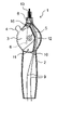
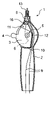
まず図1および図2を参照して、カテーテル用ハンドルを備えたカテーテルの全体を説明する。カテーテル21は、カテーテルチューブ22と、カテーテルチューブ22の近位側に設けられたハンドル1とを有する。カテーテルチューブ22の遠位側には電極23が備わっており、内部にワイヤと導線が配置されている。カテーテル21は、例えば、カテーテルチューブ22を患者の血管内を通って心臓まで到達させて、心臓における不整脈の検査や治療に用いられる。本発明において、カテーテルあるいはカテーテル用ハンドルの近位側とは、カテーテルの延在方向に対して使用者つまり術者の手元側の方向を指し、遠位側とは近位側の反対方向、すなわち処置対象側の方向を指す。
First, referring to FIGS. 1 and 2, the entire catheter provided with a catheter handle will be described. The
カテーテルチューブ22は、可撓性を有する管状構造を有しており、例えば、ポリオレフィン樹脂(例えば、ポリエチレンやポリプロピレン)、ポリアミド樹脂(例えば、ナイロン)、ポリエステル樹脂(例えば、PET)、芳香族ポリエーテルケトン樹脂(例えば、PEEK)、ポリエーテルポリアミド樹脂、ポリウレタン樹脂、ポリイミド樹脂、フッ素樹脂(例えば、PTFE、PFA、ETFE)等の合成樹脂や、ステンレス鋼、炭素鋼、ニッケルチタン合金等の金属から構成することができる。金属材料は、合成樹脂チューブ内に埋め込まれた金属線材としても用いることができる。カテーテルチューブ22の軸方向(遠近方向)の長さは、ハンドルの同方向の長さの数倍から数十倍程度長くなっており、例えば、500mm~1200mm程度である。カテーテルチューブ22の外径は、例えば、0.6mm~3mm程度とすればよい。
The
カテーテルチューブ22は内腔を有しており、内部に1つの内腔を有するシングルルーメン構造であっても、複数の内腔を有するマルチルーメン構造のいずれであってもよい。カテーテルチューブ22の内腔には、電極23に接続した導線や、カテーテルチューブ22の遠位側を屈曲させるためのワイヤが配置される。カテーテルチューブ22の内腔に配される導線は1本であっても複数本であってもよいが、通常は電極23はカテーテルチューブ22に複数設けられることから、導線も各電極23に接続するために複数設けられる。導線は導線群として配されてもよい。複数の導線は、それぞれ別のルーメンに配置されてもよく、同一のルーメンに配置されてもよい。また、複数の導線を束ねて配置することもできる。
The
カテーテルチューブ22の遠位側には、複数の電極23が離間して設けられている。図1では、先端電極23Aと複数のリング状電極23Bが設けられている。電極カテーテルでは、電極23を患者の心臓に接触させ、不整脈の検査や治療が行われる。電極23は、例えば、銅、金、白金、アルミニウム、鉄、またはこれらの合金等の金属材料から構成することができる。なお、カテーテルの使用時におけるX線に対する造影性を良好にするために、電極23は、白金またはその合金から構成されていることが好ましい。
A plurality of
カテーテル用ハンドル1はカテーテルチューブ22の近位側に設けられ、カテーテルとして組み立てた際には、カテーテルチューブ22の内腔に配されたワイヤ8の遠位側がカテーテルチューブ22、例えば、カテーテルチューブ22の遠位側1/3の部分に固定され、近位側がハンドル1に固定される(図2を参照)。導線9は、遠位側がカテーテルチューブ22に固定され、具体的には、カテーテルチューブ22に設けられた電極23に接続され、近位側がハンドル1内を通って検出器や電源に接続される。
The catheter handle 1 is provided on the proximal side of the
ワイヤ8は、ハンドル1の操作によってカテーテルチューブ22を屈曲させるために設けられ、例えば、ステンレス鋼、炭素鋼、ニッケルチタン合金等の金属線材や、ポリアミド樹脂(例えば、ナイロン)、ポリオレフィン樹脂(例えば、ポリエチレンやポリプロピレン)、ポリエステル樹脂(例えば、PET)、芳香族ポリエーテルケトン樹脂(例えば、PEEK)、ポリイミド樹脂、フッ素樹脂(例えば、PTFE、PFA、FEP、ETFE)等の合成樹脂から形成された線条を用いることができる。ワイヤ8は、1本の線材であってもよく、複数の線状物からなる構造を有していてもよい。ワイヤ8の径(直径)としては、例えば、100μm~500μm程度とすることができる。ワイヤ8は、コイル状の金属や合成樹脂によって形成された筒体によって被覆されていてもよい。
The
導線9は、少なくとも導電性材料を含んで構成されていればよく、例えば、鉄線、銀線、ステンレス線、銅線、タングステン線、ニッケルチタン線、これらの合金等を用いることができる。導線9は、導電性材料を芯材として含み、当該芯材が絶縁性材料で被覆されていることが好ましい。絶縁性材料としては、フッ素樹脂(例えば、PTFE、PFA、FEP、ETFE)、ポリオレフィン樹脂(例えば、ポリエチレンやポリプロピレン)、ポリ塩化ビニル樹脂等を用いることができる。
The
カテーテル用ハンドルの詳細について、図2~図9を参照して説明する。なお、図3は回転部材によってワイヤを最も牽引していない状態を表し、図4は回転部材によってワイヤを最も牽引している状態を表している。また図6では、便宜上、ハンドル本体の断面部分のハッチングを省略している。 Details of the catheter handle will now be described with reference to FIGS. 3 shows a state in which the wire is least pulled by the rotating member, and FIG. 4 shows a state in which the wire is most pulled by the rotating member. Also, in FIG. 6, hatching of the cross-sectional portion of the handle body is omitted for the sake of convenience.
ハンドル1は、カテーテルチューブ22の近位側が接続されるハンドル本体2と、ハンドル本体2に対して回転自在に設けられた回転部材3とを有する。回転部材3は、ハンドル1の遠近方向と幅方向に対して垂直な回転軸5を有しており、回転軸5を中心として、遠近方向と幅方向を含んで形成される平面上で回転移動可能に形成されている。回転移動とは、回転軸5を固定した回転部材3の回転をいう。なお、必要に応じて回転部材3そのものがハンドル1内で移動可能な構成であってもよく、このような移動は回転部材の移動といい、回転部材3の回転移動とは異なる。
The
ハンドル1において、遠近方向とは、上記に説明したハンドル1の近位側から遠位側に延びる方向、またはその逆方向を意味し、幅方向は遠近方向に対して垂直方向を意味する。また、回転軸5が延びる方向を回転軸方向と称する。ハンドル1は、回転軸方向に対して上側と下側が定められ、回転軸方向はハンドル1の厚み方向に相当する。図2ではハンドル1を上側から見た外観図が示されている。
In the
ハンドル本体2の内部には、回転部材3とともに、ワイヤ8と導線9が配置される。ハンドル本体2は、遠位側にカテーテルチューブ22を接続する接続口13を有しており、カテーテルチューブ22内に配置されたワイヤ8と導線9の近位側が、接続口13を通ってハンドル本体2内に延在している。図9では、ハンドル本体2が、回転部材3を回転軸方向の上側と下側の両側から挟むように配置されているが、回転部材3の片側のみにハンドル本体2が設けられてもよい。前者の場合、ハンドル本体2は例えば、回転部材3の下側に配置された第1ハンドル部材2Aと、回転部材3の上側に配置された第2ハンドル部材2Bとから構成され、第1ハンドル部材2Aと第2ハンドル部材2Bとによって形成されるハンドル本体2の内部空間に回転部材3が保持される。後者の場合、ハンドル本体2の表面に回転部材3が露出して配置される。ハンドル本体2は、例えば合成樹脂から形成することができる。
Inside the
回転部材3は、ハンドル本体2に対して回転自在に設けられ、図3や図4に示すように、ワイヤ8の近位側が固定される。回転部材3には、ワイヤ8の近位側を固定するワイヤ係止部6が備えられ、ワイヤ8の近位側がワイヤ係止部6に固定されることが好ましい。ワイヤ8の回転部材3への固定方法は、例えば、接着剤による接着、合成樹脂を溶かして固定する溶着、ネジ等の別部材を用いた固定、凹凸の嵌合などの方法や、これらの組み合わせなどが挙げられる。回転部材3は、例えば合成樹脂から形成することができる。回転部材3は筐体として構成され、内部にワイヤ8の近位側が配置されることが好ましい。この場合、回転部材3にはワイヤ8の挿入口が設けられ、ワイヤ8の近位側が挿入口を通って回転部材3に導入されることができる。回転部材3を構成する筐体は2つ以上の部材から構成され、これらの部材間にワイヤ8を挟むことにより、ワイヤ8を固定することができる。
The rotating
ハンドル1は、回転部材3を回転移動させることにより、カテーテルチューブ22の内腔に配されたワイヤ8を遠近方向に移動することができる。図面に示したハンドル1では、回転部材3を反時計回りに回転移動させることで、ワイヤ8を近位側に牽引することができ、図3に示した状態から図4に示した状態に回転部材3を回転変位させることでワイヤ8が近位側に牽引され、カテーテルチューブ22の遠位側を屈曲させることができる。回転部材3が回転移動可能な角度範囲は、カテーテルあるいはハンドルの操作性を良好にする点から、25°以上が好ましく、35°以上がより好ましく、また90°以下が好ましく、60°以下がより好ましい。なお前記角度範囲は、回転部材3上の任意の1点を見たときに、当該点が回転部材3の回転によって移動可能な角度範囲を意味する。
The
ハンドル1は、ワイヤ8を近位側に牽引することによって、カテーテルチューブ22の遠位側を屈曲させ、ワイヤ8を遠位側に押し出すことによってカテーテルチューブ22の遠位側を屈曲させるものであってもよい。ワイヤ8の遠位側がカテーテルチューブ22の遠位側に固定されていると、ワイヤ8を近位側から押し込むことによっても、カテーテルチューブ22を屈曲させることができる。
The
回転部材3は、ハンドル本体2の外側から回転操作可能な操作部4を備えている。操作部4はハンドル1の外側に露出して設けられ、使用者が操作部4に触れて回転部材3を回転移動できるように形成されている。操作部4は、回転部材3の外縁の一部を構成している。操作部4は、回転軸5に対して外方に突出した突出部を含んで形成されており、その突出部は、ハンドル本体2から少なくとも一部が露出していることが好ましい。図6に示すように、操作部4は、回転部材3の回転軸5を中心とした円弧の一部を含むように形成されていてもよい。また、当該円弧から回転軸5に対して外方に突出した突出部を含むように操作部4が形成されていてもよい。
The rotating
図5には回転部材3等を取り除いたハンドル本体2の内部構造を示したが、図5に示すように、ハンドル本体2内には、回転部材3の回転軸方向からの平面視で、回転部材3が回転移動可能な第1空間11と導線9を配置するための第2空間12が設けられている。回転部材3は、その回転軸5を中心とした回転に伴い、第1空間11内で移動可能である。つまり、図3および図4に示すように、回転の前後で、回転軸5の位置は同一であり、第1空間11内での回転部材3の位置が異なる。
FIG. 5 shows the internal structure of the
第1空間11は、回転部材3の回転移動の前後においてハンドル本体2内で回転部材3が存在しうる空間であり、第1空間11内で回転部材3がその回転軸5を中心として回転移動可能である。回転部材3が回転移動可能な角度範囲は、第1空間11のサイズやハンドル本体2に設けられた回転部材3のための開口部の大きさによって、設定することができる。ハンドル本体2内に設けた仕切り部10や突起部に回転部材3が接触することや、操作部4がハンドル本体2の筐体部分に接触することによって、回転部材3が回転移動可能な角度範囲が規制されてもよい。
The
第2空間12はハンドル本体2内で導線9が配置されうる空間であり、図5では、ハンドル本体2内で、第1空間11を含む仕切り部10で囲まれた部分と後述するワイヤ挿入空間15以外の領域が、第2空間12に相当する。第2空間12は、ハンドル本体2内で、第1空間11よりも遠位側から第1空間11よりも近位側にかけて設けられている。これにより、導線9を接続口13からハンドル本体2内に導入して、導線9の近位側をハンドル本体2内の第2空間12を通って回転部材3や第1空間11の近位側まで延在させることができる。第2空間12は、最も狭い部分が、好ましくは0.5mm以上3.0mm以下の幅、より好ましくは1.0mm以上2.5mm以下の幅で形成され、これにより第2空間12内で導線9を安定して配置しやすくなる。
The
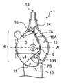
図6に示すように、ハンドル1は、回転部材3の回転軸5を挟んで、操作部4が幅方向の一方側に設けられ、第2空間12が幅方向の他方側に設けられている。そして、回転部材3は、回転軸5の中心を通り幅方向に延びる仮想直線W上において、回転軸5の中心から操作部4が設けられた幅方向の一方側の回転部材3の外縁までの長さL1が、回転軸5の中心から第2空間12側である幅方向の他方側の回転部材3の外縁までの長さL2よりも長く形成されている。このようにハンドル1を形成することにより、ハンドル本体2をコンパクトかつ薄型に形成しつつ、導線9に無理な負荷をかけることなく配置することが可能な第2空間12を、第1空間11と幅方向に並べて形成することが可能となる。すなわち、ハンドル1の幅方向の他方側では、回転部材3は回転軸中心から外縁までの長さL2が短く形成されているため、ハンドル本体2の幅方向の他方側の幅を大きく広げなくても、導線9を配置するための第2空間12を確保しやすくなる。また、接続口13からハンドル本体2内に導入された導線9を、急な角度で屈曲させることなくハンドル本体2内に配置することが可能となる。一方、ハンドル1の幅方向の一方側では、回転部材3の回転軸中心から外縁までの長さL1が長く形成されているため、操作部4を軽い力で操作しやすくなる。なお回転部材3は、第1空間11に配置され、回転部材3の回転軸5を中心に回転移動したいずれかの状態で、上記のような位置関係にあればよく、回転部材3の回転移動可能な角度範囲のうち、60%以上の角度範囲で上記のように形成されていることが好ましく、75%以上がより好ましく、90%以上がさらに好ましい。
As shown in FIG. 6, the
上記に説明した回転部材3の回転軸中心から外縁までの長さL1と長さL2について、長さL1は長さL2の1.5倍以上が好ましく、2.0倍以上がより好ましく、2.5倍以上がさらに好ましく、これにより上記に説明した作用効果がより奏されやすくなる。一方、回転部材3の幅方向の他方側の強度を確保し、また回転部材3をコンパクトに形成する観点から、長さL1は長さL2の8.0倍以下が好ましく、6.0倍以下がより好ましく、5.0倍以下がさらに好ましい。
Regarding the length L1 and the length L2 from the center of the rotation axis to the outer edge of the rotating
回転部材3の形状は、上記に説明したように、操作部4が設けられた幅方向の一方側が、第2空間12側に位置する幅方向の他方側よりも、回転軸中心から回転部材3の外縁までの長さが長く形成されている限り、特に限定されない。なお、導線9を配置するための第2空間12を、回転部材3の回転軸5の近くに配置できるようにする観点から、回転部材3は次のように形成されることが好ましい。すなわち回転部材3は、図7に示すように、回転軸中心から回転部材3の外縁までの最長長さを長さLとしたとき、回転軸中心から回転部材の外縁までの長さが0.5L以下となる角度領域、すなわち短径角度領域Sを有し、当該角度領域Sが、回転部材3の回転軸中心の120°以上の範囲であることが好ましい。このように短径角度領域Sを有するように回転部材3が形成されていれば、ハンドル本体2内に導線9を急な角度で屈曲させることなく配置しやすくなる。また、第2空間12と回転軸5とを近くに配置できるようになるため、ハンドル1をより小さいサイズに形成することができる。なお、短径角度領域Sは、回転部材3の回転軸中心の150°以上の範囲で形成されていることがより好ましく、180°以上がさらに好ましい。また、回転軸中心から回転部材3の操作部4までの長さが最長長さLとなることが好ましい。
As described above, the shape of the rotating
図8には、回転部材3の他の例を示した。図8(a),(b)に示した回転部材3はいずれも、短径角度領域Sが120°以上となる形状を有している。図8(a),(b)に示したような形状の回転部材3であっても、回転部材3の操作性を確保しながら、ハンドル本体2内に導線9を配置するための第2空間12を広く確保しやすくなる。なお、図8(a),(b)に示したような回転部材3をハンドル本体2に設ける場合、ハンドル本体2や後述する仕切り部10の形状は、回転部材3の形状に合わせて適宜設定すればよい。
FIG. 8 shows another example of the rotating
回転部材3は、より軽い力でワイヤ8の牽引操作が可能となり、また当該操作の細かな制御が容易になる点から、ワイヤ係止部6の回転軸中心からの長さが、操作部4の回転軸中心からの長さよりも短いことが好ましい。より好ましくは、ワイヤ係止部6の回転軸中心からの長さが、操作部4の回転軸中心からの長さの80%以下であり、さらに好ましくは65%以下である。一方、回転部材3の回転操作によるワイヤ8の牽引長さを確保する観点から、ワイヤ係止部6の回転軸中心からの長さは、操作部4の回転軸中心からの長さの10%以上が好ましく、20%以上がより好ましい。なお、ワイヤ係止部6の回転軸中心からの長さは、回転部材3の回転軸中心から、ワイヤ係止部6のワイヤ8の固定点までの長さを意味する。ここで、ワイヤ係止部6のワイヤ8の固定点は、ワイヤ8がワイヤ係止部6によって固定される部分と固定されない部分との境界点に相当する。ワイヤ8は当該固定点より遠位側では固定されない。操作部4の回転軸中心からの長さは、回転部材3の回転軸中心から操作部4までの長さのうちの最長長さを意味する。
Rotating
ワイヤ係止部6は、図3や図4に示すように、回転部材3の回転軸中心よりも近位側に位置することが好ましい。これにより、回転部材3を回転移動させた際に、ワイヤ8を牽引してワイヤ8の近位側をハンドル本体2内に引き込みやすくなる。この場合、ワイヤ係止部6は、回転部材3が回転移動可能な50%以上の角度範囲で、ワイヤ係止部6が回転部材3の回転軸中心よりも近位側に位置していることが好ましく、70%以上の角度範囲がより好ましく、90%以上の角度範囲がさらに好ましい。一方、ワイヤをカテーテル先端側へ押し込んで屈曲させる構造のカテーテルである場合、牽引して屈曲させる構造とは逆に、ワイヤ係止部6は回転部材3の回転軸中心よりも遠位側に位置することが好ましい。この場合、ワイヤ係止部6は、回転部材3が回転移動可能な50%以上の角度範囲で、ワイヤ係止部6が回転部材3の回転軸中心よりも遠位側に位置していることが好ましく、70%以上の角度範囲がより好ましく、90%以上の角度範囲がさらに好ましい。
As shown in FIGS. 3 and 4, the
ワイヤを牽引してカテーテルの先端を屈曲させる構造のカテーテルである場合、回転部材3は、回転部材3を回転移動させてワイヤ8を最も牽引した状態で、ワイヤ8が回転部材3の回転軸5の外周側に接するようにワイヤ係止部6が設けられていることが好ましい。このようにワイヤ係止部6が設けられることにより、回転部材3を回転移動させた際に、ワイヤ8を牽引しやすくなる。なお、ワイヤ係止部6は、回転部材3によってワイヤ8を最も牽引していない状態、すなわち回転部材3を回転移動させてワイヤ係止部6が最も遠位側にある状態で、回転部材3の回転軸中心よりも幅方向の一方側、すなわち操作部4側に位置することが好ましい。
In the case of a catheter having a structure in which a wire is pulled to bend the distal end of the catheter, the rotating
回転部材3の回転操作によってより軽い力でワイヤ8を操作可能となる点から、回転部材3の回転軸中心は、ハンドル1の幅方向において、接続口13と重なる位置にあるか、接続口13よりも幅方向の他方側、すなわち第2空間12側に位置することが好ましい。例えば、回転部材3の回転軸中心は、ハンドル1の幅方向において、接続口13と重なる位置にあるか、接続口13よりも幅方向の他方側に5mm以内に位置することが好ましく、3mm以内に位置することがより好ましい。一方、第2空間12をより広く確保する観点から、回転部材3の回転軸中心は、ハンドル1の幅方向において、接続口13よりも幅方向の一方側、すなわち操作部4側に位置していてもよい。この場合、回転部材3の操作性を確保する点から、回転部材3の回転軸中心は、ハンドル1の幅方向において、接続口13よりも幅方向の一方側に5mm以内に位置することが好ましく、3mm以内に位置することがより好ましい。
Since the
ハンドル本体2は、幅方向の一方側と他方側が略対称に形成されていることが好ましい。例えば、ハンドル本体2は、幅方向の他方側、すなわち第2空間12側が過度に広がった形状でないことが好ましい。ハンドル本体2は、例えば、回転部材3の回転軸中心を通り幅方向に延びる仮想直線W上において、回転軸中心を挟んだ一方側と他方側の長さ、すなわち回転軸中心からハンドル本体2の外縁までの長さの差が10mm以内であることが好ましく、8mm以内がより好ましく、5mm以内がさらに好ましい。
The
ハンドル本体2内において、回転部材3が存在しうる第1空間11と、導線9が配置されうる第2空間12は、仕切り部10によって区分されていることが好ましい。つまり、第1空間11と第2空間12の境界に仕切り部10が設けられていることが好ましい。これにより、導線9が回転部材3と接触することが防止され、導線9が回転部材3に巻き込まれたりして導線9が擦過したり断線することが起こりにくくなる。
A
仕切り部10は、第1空間11と第2空間12の境界に連続的に設けられていてもよく、断続的に設けられていてもよい。なお、導線9と回転部材3との接触ができるだけ起こらないようにする点から、仕切り部10は、第1空間11と第2空間12の境界の50%以上に設けられることが好ましく、70%以上がより好ましく、80%以上がさらに好ましく、90%以上がさらにより好ましい。また、仕切り部10は、ハンドル本体2内で第1空間11と第2空間12が幅方向に並んで存在する部分の第1空間11と第2空間12の境界に少なくとも設けられることが好ましい。仕切り部10が断続的に設けられる場合は、その断続部分の1つ当たりの長さ、すなわち離間距離は、導線9と回転部材3との接触を防ぐ点から、5mm以下が好ましく、4mm以下がより好ましく、3mm以下がさらに好ましい。断続部分の長さの下限は特に限定されないが、例えば0.5mm以上であればよい。なお、第1空間11と第2空間12の境界の少なくとも一部には、ワイヤ8を第1空間11や回転部材3に引き込むための隙間、あるいは断続部分が形成されていることが好ましい。
The
図6等に示すように、回転部材3は、回転軸5を中心とする回転移動によって、回転部材3の外縁の一部が仕切り部10の一部に接するように形成されていることが好ましい。このように仕切り部10を設けることより、ハンドル本体2内において、回転部材3の回転移動範囲を規制することができる。図6の配置において、仕切り部10は、回転部材3を時計回りに回転移動させたときに、回転部材3の外縁の一部が接するように設けられるとともに、回転部材3を反時計回りに回転移動させたときに、回転部材3の外縁の他の一部が接するように設けられることが好ましい。
As shown in FIG. 6 and the like, the rotating
回転部材3と仕切り部10はまた、次のように構成されていることが好ましい。すなわち、図6に示すように、仕切り部10は、第1仕切り直線部10Aと第2仕切り直線部10Bとを有し、回転部材3の外縁は、第1直線部7Aと第2直線部7Bとを有し、回転部材3の回転軸5を中心とする回転移動によって、第1直線部7Aが第1仕切り直線部10Aに近づき、第2直線部7Bが第2仕切り直線部10Bから離れる、または、第2直線部7Bが第2仕切り直線部10Bに近づき、第1直線部7Aが第1仕切り直線部10Aから離れるように構成されていることが好ましい。この場合、第1直線部7Aと第1仕切り直線部10Aは、互いに近接した状態で略平行となっていることが好ましく、第2直線部7Bと第2仕切り直線部10Bは、互いに近接した状態で略平行となっていることが好ましい。ここで、第1直線部7Aと第1仕切り直線部10Aとが互いに近接した状態とは、図6に示すように、回転部材3を時計回りに回転移動させた後の状態をいう。このように回転部材3と仕切り部10が形成されていれば、仕切り部10の第1仕切り直線部10Aと第2仕切り直線部10Bによって、回転部材3の回転移動範囲が確実に規制されやすくなる。
The rotating
図5や図6に示すように、ハンドル本体2には、回転部材3より遠位側に、ハンドル本体2の遠位側(接続口13)から挿入されたワイヤ8と導線9を分岐するための分岐部14が設けられ、分岐部14において、第1空間11に連通したワイヤ挿入空間15が設けられることが好ましい。分岐部14は、ハンドル本体2内において、第1空間11よりも遠位側に位置し、ワイヤ8を配置するための空間と導線9を配置するための空間とに分岐する部分であり、ワイヤ8を配置するための空間がワイヤ挿入空間15となり、導線9を配置するための空間が第2空間12となる。このように分岐部14が設けられていれば、回転部材3を回転移動させてワイヤ8を近位側に牽引または遠位側へ押し込んだ際に、ワイヤ8とともに導線9も回転部材3に引き込まれたり、ワイヤ8と導線9とが擦れ合ったりすることが防止され、それによってワイヤ8が損傷したり、ワイヤ8に無理な負荷がかかったりすることが防止される。
As shown in FIGS. 5 and 6, the
ワイヤ挿入空間15には、ワイヤ8を通すための開口を有するワイヤ案内部材16が設けられていることが好ましい。ワイヤ案内部材16の開口を通してワイヤ8を回転部材3に導入することにより、回転部材3を回転移動させた際に、安定してワイヤ8を回転部材3に引き込んで近位側に牽引することができる。また、ワイヤ案内部材16によって、導線9がワイヤ挿入空間15や回転部材3に引き込まれることを防止することもできる。ワイヤ案内部材16は、例えば合成樹脂から形成することができる。
A
ワイヤ案内部材16の開口は、遠位側の開口径が近位側の開口径よりも大きいことが好ましい。このようにワイヤ案内部材16が形成されていれば、ハンドル本体2の接続口13から挿入されたワイヤ8を、無理な負荷がかかることなくワイヤ案内部材16の開口に導入しやすくなる。ワイヤ8が、コイル状の金属や合成樹脂によって形成された筒体によって被覆されている場合は、ワイヤ案内部材16の開口で筒体がさらに近位側に引き込まれないようにして、ワイヤ8のみを回転部材3に導入されるようにすることができる。
The opening of the
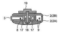
回転部材3は、回転軸5を中心に回転移動可能に形成されているとともに、任意の回転角度でハンドル本体2に対して位置固定できるように形成されていることが好ましい。この位置固定により、カテーテルチューブ22の遠位側の屈曲形状を一定に保つことができる。そのためにハンドル1は、図9に示すように、回転部材3とハンドル本体2との間に弾性部材17が設けられ、弾性部材17と回転部材3とが接触していることが好ましい。また、回転部材3が、弾性部材17を介してハンドル本体2に対して回転軸方向に押圧可能に形成されていてもよい。この場合、ハンドル1を回転軸方向に沿った断面で見たときに、回転部材3とハンドル本体2との間に弾性部材17が配置され、回転部材3を弾性部材17を介してハンドル本体2に押圧することにより、回転部材3とハンドル本体2が弾性部材17に強く押し当てられ、回転部材3がハンドル本体2に対して自由に回転移動できないようになる。このように回転部材3の回転位置を固定することにより、ワイヤ8の位置が固定されるため、カテーテルチューブ22の遠位側の屈曲形状を固定して、カテーテルチューブ22の電極23を患者の心臓の内壁等に安定して接触させることができる。一方、回転部材3のハンドル本体2に対する押圧を解除すると、回転部材3がハンドル本体2に対して回転移動できるようになる。
The rotating
弾性部材17は、シート状の弾性部材がハンドル本体2と回転部材3の間に設けられればよい。弾性部材17は、回転部材3と第1ハンドル部材2Aとの間に設けられてもよく、回転部材3と第2ハンドル部材2Bとの間に設けられてもよい。弾性部材17の形状は特に限定されない。図9では、回転部材3の回転軸5を取り囲むように環状の弾性部材17が設けられている。弾性部材17は、ハンドル本体2に取り付けられていてもよく、回転部材3に取り付けられていてもよい。弾性部材17は、弾性変形可能な材質で構成されることが好ましく、例えば、シリコーンゴム、ニトリルゴム、フッ素ゴム、天然ゴム等のゴム;スチレン-イソプレン-スチレンブロック共重合体(SIS)、スチレン-ブタジエン-スチレンブロック共重合体(SBS)、スチレン-エチレン-ブタジエン-スチレンブロック共重合体(SEBS)、スチレン-エチレン-プロピレン-スチレンブロック共重合体(SEPS)等のスチレン系エラストマー;ポリウレタン等のウレタン系エラストマーなどで構成することができる。
The
回転部材3を弾性部材17を介してハンドル本体2に対して押圧する手段は特に限定されないが、図9では、ボルト18とナット19が使用されている。具体的には、回転部材3の回転軸部分にハンドル本体2と回転部材3を貫通するボルト18を設け、把手が付いたナット19をボルト18に対して螺合している。ナット19をボルト18に対して締め付けることで、回転部材3を弾性部材17を介してハンドル本体2に対して押圧することができる。
The means for pressing the
以上説明した本発明のカテーテル用ハンドルについて、簡単にまとめる。本発明のカテーテル用ハンドルとは、ワイヤと導線が内部に配置されたカテーテルチューブを接続して操作するためのものであって;ハンドルは、カテーテルチューブの近位側が接続されるハンドル本体と、ハンドル本体に対して回転自在に設けられ、ワイヤの近位側が固定される回転部材とを有し;回転部材は、ハンドルの遠近方向と幅方向に対して垂直な回転軸を有し、ハンドル本体の外側から回転操作可能な操作部を備え;ハンドル本体内には、回転部材の回転軸方向からの平面視で、回転部材が回転移動可能な第1空間と導線を配置するための第2空間が設けられ、第2空間が、第1空間よりも遠位側から第1空間よりも近位側にかけて設けられており;回転部材の回転軸を挟んで、操作部は、ハンドルの幅方向の一方側に設けられ、第2空間は、ハンドルの幅方向の他方側に設けられており;回転部材は、第1空間に配置され回転軸を中心に回転移動したいずれかの状態で、回転軸中心を通り幅方向に延びる仮想直線上において、回転軸中心から幅方向の一方側の回転部材の外縁までの長さL1が、回転軸中心から幅方向の他方側の回転部材の外縁までの長さL2よりも長いところに特徴を有する。 The catheter handle of the present invention described above will be briefly summarized. The catheter handle of the present invention is for connecting and manipulating a catheter tube in which a wire and a conducting wire are arranged; a rotating member provided rotatably with respect to the main body and fixed at the proximal side of the wire; The handle body has a first space in which the rotating member can be rotated and a second space in which the conducting wire is arranged when viewed from above in the rotation axis direction of the rotating member. The second space is provided from the distal side of the first space to the proximal side of the first space; and the second space is provided on the other side in the width direction of the handle; on the imaginary straight line extending in the width direction, the length L1 from the center of the rotation shaft to the outer edge of the rotating member on one side in the width direction is the length from the center of the rotation shaft to the outer edge of the rotating member on the other side in the width direction It is characterized by being longer than L2.
本発明のカテーテル用ハンドルは、上記のように構成されることにより、ハンドル本体をコンパクトかつ薄型に形成しつつ、ハンドル本体内に、導線を配置するための第2空間を、導線に無理な負荷をかけることなく形成することができる。一方、ワイヤを牽引する回転部材は、操作部側において回転軸中心から外縁までの長さが長く形成されているため、回転部材を軽い力で操作しやすくなる。そのため、本発明のカテーテル用ハンドルは、回転部材の操作性を確保しつつ、コンパクトな大きさで厚みを薄く形成することができる。 With the catheter handle of the present invention configured as described above, the handle body can be made compact and thin, while the second space for arranging the lead wire is provided in the handle body to prevent excessive load on the lead wire. can be formed without applying On the other hand, since the rotating member for pulling the wire is formed to have a long length from the center of the rotating shaft to the outer edge on the operating portion side, the rotating member can be easily operated with a light force. Therefore, the catheter handle of the present invention can be formed to have a compact size and a small thickness while ensuring the operability of the rotating member.
ハンドル本体は、遠位側に、カテーテルチューブを接続する接続口を有し、回転軸中心は、幅方向において、接続口と重なる位置にあるか、接続口よりも幅方向の他方側に位置することが好ましい。カテーテル用ハンドルは、回転部材を回転移動させることによってワイヤを近位側に牽引することができるが、このような位置に回転部材の回転軸中心があれば、より軽い力でワイヤを牽引することができる。 The handle body has a connection port for connecting the catheter tube on the distal side, and the center of the rotation axis is located at a position overlapping the connection port in the width direction or on the other side of the connection port in the width direction. is preferred. The catheter handle can pull the wire proximally by rotating the rotating member, but if the rotation axis of the rotating member is at such a position, the wire can be pulled with a lighter force. can be done.
回転部材は、ワイヤの近位側を固定するワイヤ係止部を備えており、ワイヤ係止部の回転軸中心からの長さが、操作部の回転軸中心からの長さよりも短いことが好ましい。このようにワイヤ係止部が設けられていれば、より軽い力でワイヤの牽引操作が可能となるとともに、当該操作の細かな制御が容易になる。 The rotating member has a wire locking portion that fixes the proximal side of the wire, and the length of the wire locking portion from the center of the rotation axis is preferably shorter than the length from the center of the rotation axis of the operating portion. . If the wire locking portion is provided in this manner, the wire can be pulled with less force, and fine control of the operation can be facilitated.
ワイヤ係止部は、回転部材の回転軸中心よりも近位側に位置することが好ましい。これにより、回転部材を回転移動させた際に、ワイヤを近位側に牽引してハンドル本体内に引き込みやすくなる。 It is preferable that the wire locking portion be located on the proximal side with respect to the center of the rotation axis of the rotating member. As a result, when the rotating member is rotated, the wire can be easily pulled proximally into the handle body.
回転部材は、回転軸中心から回転部材の外縁までの最長長さLに対して、回転軸中心から回転部材の外縁までの長さが0.5L以下となる角度領域を有し、前記角度領域が回転部材の回転軸中心の120°以上の範囲であることが好ましい。このように回転部材を形成することにより、ハンドル本体内において、導線を配置するための第2空間を、回転部材の回転軸の近くに形成できるようになる。 The rotating member has an angular region in which the length from the center of the rotating shaft to the outer edge of the rotating member is 0.5L or less with respect to the longest length L from the center of the rotating shaft to the outer edge of the rotating member. is preferably in the range of 120° or more from the rotation axis center of the rotating member. By forming the rotating member in this manner, a second space for arranging the conductor wire can be formed near the rotation axis of the rotating member in the handle body.
第1空間と第2空間の境界には仕切り部が設けられていることが好ましい。仕切り部を設けることにより、導線が回転部材と接触することが防止され、導線が回転部材に巻き込まれたりして導線が擦過したり断線することが起こりにくくなる。 A partition is preferably provided at the boundary between the first space and the second space. By providing the partition portion, the conductor is prevented from coming into contact with the rotating member, and the conductor is less likely to be scratched or broken due to being caught in the rotating member.
回転部材は、回転軸を中心とする回転移動によって、回転部材の外縁の一部が仕切り部の一部に接することが好ましい。このように仕切り部を設けることより、回転部材の回転移動範囲を規制することができる。 It is preferable that a part of the outer edge of the rotating member comes into contact with a part of the partition part by rotational movement about the rotating shaft. By providing the partition portion in this manner, the rotational movement range of the rotating member can be restricted.
仕切り部は、第1仕切り直線部と第2仕切り直線部とを有し、回転部材の外縁は、第1直線部と第2直線部とを有し、回転部材の回転軸を中心とする回転移動によって、第1直線部が第1仕切り直線部に近づき、第2直線部が第2仕切り直線部から離れる、または、第2直線部が第2仕切り直線部に近づき、第1直線部が第1仕切り直線部から離れるように形成されていることが好ましい。このように回転部材と仕切り部が形成されていれば、仕切り部の第1仕切り直線部と第2仕切り直線部によって、回転部材の回転移動範囲が確実に規制されやすくなる。 The partition portion has a first partition straight portion and a second partition straight portion, the outer edge of the rotating member has a first straight portion and a second straight portion, and the rotating member rotates around the rotation axis. The movement causes the first straight line portion to approach the first partition straight portion and the second straight portion to leave the second partition straight portion, or the second straight portion to approach the second partition straight portion and move the first straight portion to the second partition straight portion. It is preferable to form so that it may separate from 1 partition linear part. If the rotating member and the partition are formed in this manner, the rotational movement range of the rotating member can be reliably and easily restricted by the first partition straight portion and the second partition straight portion of the partition.
回転部材とハンドル本体との間には弾性部材が設けられ、回転部材は、弾性部材を介してハンドル本体に対して回転軸方向に押圧可能であることが好ましい。このようにハンドルが形成されていれば、回転部材を弾性部材を介してハンドル本体に押圧することによって、回転部材を任意の回転位置でハンドル本体に対して位置固定することができる。これにより、カテーテルチューブの遠位側の屈曲形状を固定することができる。 Preferably, an elastic member is provided between the rotating member and the handle body, and the rotating member can be pressed against the handle body in the rotation axis direction via the elastic member. If the handle is formed in this manner, the rotating member can be fixed to the handle body at any rotational position by pressing the rotating member against the handle body via the elastic member. Thereby, the bent shape of the distal side of the catheter tube can be fixed.
ハンドル本体は、回転部材の遠位側に、ハンドル本体の遠位側から挿入されたワイヤと導線を分岐するための分岐部を有し、分岐部において、ハンドル本体内に、第1空間に連通したワイヤ挿入空間が設けられていることが好ましい。このようにハンドル本体に分岐部が設けられていれば、回転部材を回転移動させてワイヤを近位側に牽引した際に、ワイヤとともに導線が回転部材に引き込まれることが防止され、それによってワイヤが損傷したり、ワイヤに無理な負荷がかかったりすることが防止される。 The handle body has a branch portion for branching the wire inserted from the distal side of the handle body and the conducting wire on the distal side of the rotating member, and the branch portion communicates with the first space in the handle body. It is preferable that a space for inserting a wire is provided. If the handle body is provided with the branch portion in this way, when the rotating member is rotated to pull the wire proximally, the lead wire is prevented from being pulled into the rotating member together with the wire. are prevented from being damaged and the wires from being overloaded.
ワイヤ挿入空間には、ワイヤを通すための開口を有するワイヤ案内部材が設けられ、ワイヤ案内部材の開口は、遠位側の開口径が近位側の開口径よりも大きいことが好ましい。ワイヤ案内部材の開口を通してワイヤを回転部材に導入することにより、回転部材を回転移動させた際に、安定してワイヤを回転部材に引き込むことができる。 A wire guide member having an opening for passing a wire is provided in the wire insertion space, and the diameter of the opening of the wire guide member is preferably larger on the distal side than on the proximal side. By introducing the wire into the rotating member through the opening of the wire guide member, the wire can be stably drawn into the rotating member when the rotating member is rotated.
本発明はまた、本発明のカテーテル用ハンドルと、ハンドル本体の遠位側に接続されたカテーテルチューブと、遠位側がカテーテルチューブに固定され、近位側が回転部材に固定されたワイヤと、遠位側がカテーテルチューブに固定され、近位側が第2空間を通って回転部材の近位側に延在する導線とを有するカテーテルも提供する。本発明のカテーテルは上記に説明したハンドルを備えているため、ハンドルの操作性を確保しつつ、ハンドルをコンパクトかつ薄く形成することができる。 The present invention also provides a catheter handle of the present invention, a catheter tube connected to the distal side of a handle body, a wire having a distal side fixed to the catheter tube and a proximal side fixed to a rotating member, and a distal A catheter having a side fixed to the catheter tube and a proximal side extending through the second space to the proximal side of the rotating member. Since the catheter of the present invention has the handle described above, the handle can be made compact and thin while ensuring the operability of the handle.
本願は、2018年1月31日に出願された日本国特許出願第2018-015107号に基づく優先権の利益を主張するものである。2018年1月31日に出願された日本国特許出願第2018-015107号の明細書の全内容が、本願に参考のため援用される。 This application claims the benefit of priority based on Japanese Patent Application No. 2018-015107 filed on January 31, 2018. The entire contents of the specification of Japanese Patent Application No. 2018-015107 filed on January 31, 2018 are incorporated herein by reference.
1:カテーテル用ハンドル
2:ハンドル本体、2A:第1ハンドル部材、2B:第2ハンドル部材
3:回転部材
4:操作部
5:回転軸
6:ワイヤ係止部
7A:第1直線部、7B:第2直線部
8:ワイヤ
9:導線
10:仕切り部、10A:第1仕切り直線部、10B:第2仕切り直線部
11:第1空間
12:第2空間
13:接続口
14:分岐部
15:ワイヤ挿入空間
16:ワイヤ案内部材
17:弾性部材
18:ボルト
19:把手(ナット)
21:カテーテル
22:カテーテルチューブ
23,23A,23B:電極Reference Signs List 1: catheter handle 2: handle
21: Catheter 22:
Claims (12)
前記ハンドルは、前記カテーテルチューブの近位側が接続されるハンドル本体と、前記ハンドル本体に対して回転自在に設けられ、前記ワイヤの近位側が固定される回転部材とを有し、
前記回転部材は、前記ハンドルの遠近方向と幅方向に対して垂直な回転軸を有し、前記ハンドル本体の外側から回転操作可能な操作部を備え、
前記ハンドル本体内には、前記回転部材の回転軸方向からの平面視で、前記回転部材が回転移動可能な第1空間と導線を配置するための第2空間が設けられ、前記第2空間が、前記第1空間よりも遠位側から前記第1空間よりも近位側にかけて設けられており、
前記回転部材の回転軸を挟んで、前記操作部は、前記ハンドルの前記幅方向の一方側に設けられ、前記第2空間は、前記ハンドルの前記幅方向の他方側に設けられており、
前記回転部材は、前記第1空間に配置され前記回転軸を中心に回転移動したいずれかの状態で、前記回転軸中心を通り前記幅方向に延びる仮想直線上において、前記回転軸中心から前記幅方向の前記一方側の前記回転部材の外縁までの長さL1が、前記回転軸中心から前記幅方向の前記他方側の前記回転部材の外縁までの長さL2よりも長いことを特徴とするカテーテル用ハンドル。A catheter handle for connecting and manipulating a catheter tube having wires and conductors disposed therein, the handle comprising:
The handle has a handle body to which the proximal side of the catheter tube is connected, and a rotating member provided rotatably with respect to the handle body and to which the proximal side of the wire is fixed,
The rotating member has a rotating shaft perpendicular to the distance direction and the width direction of the handle, and has an operation part that can be rotated from the outside of the handle body,
A first space in which the rotating member can rotate and a second space for arranging a conductor wire are provided in the handle main body in plan view from the rotation axis direction of the rotating member. , is provided from the distal side of the first space to the proximal side of the first space,
The operating portion is provided on one side of the handle in the width direction across the rotation axis of the rotating member, and the second space is provided on the other side of the handle in the width direction,
The rotating member is placed in the first space and rotated around the rotating shaft, and the rotating member moves from the rotating shaft center to the width direction on an imaginary straight line passing through the rotating shaft center and extending in the width direction. A catheter characterized in that a length L1 from the center of the rotation axis to the outer edge of the rotating member on the one side in the direction is longer than a length L2 from the center of the rotation axis to the outer edge of the rotating member on the other side in the width direction. handle for.
前記回転軸中心は、前記幅方向において、前記接続口と重なる位置にあるか、前記接続口よりも前記幅方向の前記他方側に位置する請求項1に記載のカテーテル用ハンドル。The handle body has a connection port on the distal side for connecting the catheter tube,
2. The catheter handle according to claim 1, wherein the center of the rotation axis overlaps with the connection port in the width direction, or is located on the other side of the connection port in the width direction.
前記ワイヤ係止部の前記回転軸中心からの長さが、前記操作部の前記回転軸中心からの長さよりも短い請求項1または2に記載のカテーテル用ハンドル。The rotating member has a wire locking portion that fixes the proximal side of the wire,
The catheter handle according to claim 1 or 2, wherein the length of the wire locking portion from the center of the rotation axis is shorter than the length of the operation portion from the center of the rotation axis.
前記回転部材の外縁は、第1直線部と第2直線部とを有し、
前記回転部材の前記回転軸を中心とする回転移動によって、前記第1直線部が前記第1仕切り直線部に近づき、前記第2直線部が前記第2仕切り直線部から離れる、または、前記第2直線部が前記第2仕切り直線部に近づき、前記第1直線部が前記第1仕切り直線部から離れる請求項6または7に記載のカテーテル用ハンドル。The partition portion has a first partition straight portion and a second partition straight portion,
the outer edge of the rotating member has a first straight portion and a second straight portion;
By rotational movement of the rotating member about the rotation axis, the first linear portion approaches the first partition linear portion and the second linear portion moves away from the second partition linear portion, or the second linear portion moves away from the second partition linear portion. The catheter handle according to claim 6 or 7, wherein the straight portion approaches the second straight partition portion and the first straight portion separates from the first straight partition portion.
前記回転部材は、前記弾性部材を介して前記ハンドル本体に対して回転軸方向に押圧可能である請求項1~8のいずれか一項に記載のカテーテル用ハンドル。An elastic member is provided between the rotating member and the handle body,
The catheter handle according to any one of Claims 1 to 8, wherein the rotating member can be pressed against the handle body in the direction of the rotation axis via the elastic member.
前記分岐部において、前記ハンドル本体内に、前記第1空間に連通したワイヤ挿入空間が設けられている請求項1~9のいずれか一項に記載のカテーテル用ハンドル。The handle body has a branching portion distal to the rotating member for branching the wire inserted from the distal side of the handle body and the conducting wire,
The catheter handle according to any one of claims 1 to 9, wherein a wire insertion space communicating with the first space is provided in the handle body in the branch portion.
前記ワイヤ案内部材の開口は、遠位側の開口径が近位側の開口径よりも大きい請求項10に記載のカテーテル用ハンドル。A wire guide member having an opening for passing the wire is provided in the wire insertion space,
11. The catheter handle according to claim 10, wherein the opening of the wire guide member has a distal opening diameter larger than a proximal opening diameter.
前記ハンドル本体の遠位側に接続されたカテーテルチューブと、
遠位側が前記カテーテルチューブに固定され、近位側が前記回転部材に固定されたワイヤと、
遠位側が前記カテーテルチューブに固定され、近位側が前記第2空間を通って前記回転部材の近位側に延在する導線とを有することを特徴とするカテーテル。a catheter handle according to any one of claims 1 to 11;
a catheter tube connected to the distal side of the handle body;
a wire having a distal end fixed to the catheter tube and a proximal end fixed to the rotating member;
A catheter having a distal side fixed to the catheter tube and a proximal side extending through the second space to the proximal side of the rotating member.
Applications Claiming Priority (3)
| Application Number | Priority Date | Filing Date | Title |
|---|---|---|---|
| JP2018015107 | 2018-01-31 | ||
| JP2018015107 | 2018-01-31 | ||
| PCT/JP2018/038241 WO2019150664A1 (en) | 2018-01-31 | 2018-10-15 | Catheter handle and catheter having same |
Publications (2)
| Publication Number | Publication Date |
|---|---|
| JPWO2019150664A1 JPWO2019150664A1 (en) | 2021-01-14 |
| JP7114635B2 true JP7114635B2 (en) | 2022-08-08 |
Family
ID=67478105
Family Applications (1)
| Application Number | Title | Priority Date | Filing Date |
|---|---|---|---|
| JP2019568858A Active JP7114635B2 (en) | 2018-01-31 | 2018-10-15 | CATHETER HANDLE AND CATHETER WITH THE SAME |
Country Status (4)
| Country | Link |
|---|---|
| US (1) | US12005200B2 (en) |
| JP (1) | JP7114635B2 (en) |
| CN (1) | CN111655322B (en) |
| WO (1) | WO2019150664A1 (en) |
Families Citing this family (2)
| Publication number | Priority date | Publication date | Assignee | Title |
|---|---|---|---|---|
| USD994880S1 (en) * | 2021-11-02 | 2023-08-08 | Abiomed, Inc. | Medical device housing |
| CN116636921A (en) * | 2022-02-24 | 2023-08-25 | 奥林巴斯医疗株式会社 | Disposal utensils |
Citations (5)
| Publication number | Priority date | Publication date | Assignee | Title |
|---|---|---|---|---|
| US5199950A (en) | 1990-12-07 | 1993-04-06 | Willy Rusch Ag | Medical instrument |
| US20080009791A1 (en) | 2005-07-11 | 2008-01-10 | Cohen Todd J | Remotely controlled catheter insertion system |
| WO2014156284A1 (en) | 2013-03-29 | 2014-10-02 | 日本ライフライン株式会社 | Medical instrument |
| US20160325076A1 (en) | 2015-05-07 | 2016-11-10 | St. Jude Medical, Cardiology Division, Inc. | Medical device including a variable torque assembly for device deflection |
| US20170291008A1 (en) | 2016-04-08 | 2017-10-12 | St. Jude Medical, Cardiology Division, Inc. | Mapping variable loop catheter handle |
Family Cites Families (11)
| Publication number | Priority date | Publication date | Assignee | Title |
|---|---|---|---|---|
| CN1824339B (en) * | 2005-02-21 | 2011-05-11 | 住友电木株式会社 | Medical implement |
| US8777929B2 (en) * | 2005-06-28 | 2014-07-15 | St. Jude Medical, Atrial Fibrillation Division, Inc. | Auto lock for catheter handle |
| CN101291695A (en) * | 2005-10-17 | 2008-10-22 | 株式会社钟化 | Medical catheter and method for manufacturing same |
| US8556850B2 (en) * | 2008-12-31 | 2013-10-15 | St. Jude Medical, Atrial Fibrillation Division, Inc. | Shaft and handle for a catheter with independently-deflectable segments |
| US20120130218A1 (en) * | 2010-11-23 | 2012-05-24 | Kauphusman James V | Medical devices having an electroanatomical system imaging element mounted thereon |
| JP5614848B2 (en) * | 2011-07-12 | 2014-10-29 | 日本ライフライン株式会社 | Catheter handle |
| JP5535260B2 (en) | 2012-03-19 | 2014-07-02 | 日本ライフライン株式会社 | Catheter handle |
| JP5416324B1 (en) * | 2012-04-06 | 2014-02-12 | オリンパスメディカルシステムズ株式会社 | Insertion equipment |
| US9174024B1 (en) * | 2013-03-15 | 2015-11-03 | St. Jude Medical Luxembourg Holdings S.À.R.L. | Steering control mechanisms for catheters |
| JP6113682B2 (en) * | 2014-03-18 | 2017-04-12 | 日本ライフライン株式会社 | Medical device handle and medical device |
| CN107185062A (en) * | 2017-07-14 | 2017-09-22 | 仝兆锋 | One kind is exclusively used in neurosurgical catheters device |
-
2018
- 2018-10-15 US US16/965,562 patent/US12005200B2/en active Active
- 2018-10-15 JP JP2019568858A patent/JP7114635B2/en active Active
- 2018-10-15 WO PCT/JP2018/038241 patent/WO2019150664A1/en not_active Ceased
- 2018-10-15 CN CN201880088103.4A patent/CN111655322B/en active Active
Patent Citations (5)
| Publication number | Priority date | Publication date | Assignee | Title |
|---|---|---|---|---|
| US5199950A (en) | 1990-12-07 | 1993-04-06 | Willy Rusch Ag | Medical instrument |
| US20080009791A1 (en) | 2005-07-11 | 2008-01-10 | Cohen Todd J | Remotely controlled catheter insertion system |
| WO2014156284A1 (en) | 2013-03-29 | 2014-10-02 | 日本ライフライン株式会社 | Medical instrument |
| US20160325076A1 (en) | 2015-05-07 | 2016-11-10 | St. Jude Medical, Cardiology Division, Inc. | Medical device including a variable torque assembly for device deflection |
| US20170291008A1 (en) | 2016-04-08 | 2017-10-12 | St. Jude Medical, Cardiology Division, Inc. | Mapping variable loop catheter handle |
Also Published As
| Publication number | Publication date |
|---|---|
| CN111655322A (en) | 2020-09-11 |
| JPWO2019150664A1 (en) | 2021-01-14 |
| US20210046285A1 (en) | 2021-02-18 |
| US12005200B2 (en) | 2024-06-11 |
| CN111655322B (en) | 2022-05-03 |
| WO2019150664A1 (en) | 2019-08-08 |
Similar Documents
| Publication | Publication Date | Title |
|---|---|---|
| US12465200B2 (en) | Steerable micro-endoscope having an electro-surgery tool | |
| US5571085A (en) | Steerable open lumen catheter | |
| CN102892453B (en) | Magnetic Guidance Catheter | |
| JP2021098094A (en) | Basket for multi-electrode array catheter | |
| EP1364677A2 (en) | Electrode array catheter | |
| JP2009522080A (en) | Vascular guide wire control device | |
| JP2020505084A (en) | Visualization of sheath | |
| US9861432B2 (en) | Rotation mechanism for bipolar and monopolar devices | |
| CN113660911B (en) | medical instruments | |
| US10905446B2 (en) | Caculus removing device | |
| CN111683716A (en) | Catheter and method of making the same | |
| US10064679B2 (en) | Endoscopic shank instrument | |
| JP7114635B2 (en) | CATHETER HANDLE AND CATHETER WITH THE SAME | |
| JP5697273B2 (en) | Tip deflectable catheter | |
| JP2015173945A (en) | Medical equipment handle and medical equipment | |
| CN104507536B (en) | The brachytherapy and electrochemotherapy conduit of combination | |
| KR100896750B1 (en) | Medical device for insertion of living body | |
| CN117561035A (en) | Medical systems, devices and related methods | |
| CN114502074B (en) | Catheter and method of manufacturing the same | |
| WO2022127905A1 (en) | Bendable puncture device and puncture system | |
| CN110536652B (en) | High-frequency treatment instrument for endoscope | |
| JP7659558B2 (en) | Electrode Catheter | |
| JP6710066B2 (en) | Catheter handle and catheter having the same | |
| JP7669366B2 (en) | Electrode Catheter | |
| JP7701213B2 (en) | Electrode Catheter |
Legal Events
| Date | Code | Title | Description |
|---|---|---|---|
| A621 | Written request for application examination |
Free format text: JAPANESE INTERMEDIATE CODE: A621 Effective date: 20210906 |
|
| TRDD | Decision of grant or rejection written | ||
| A01 | Written decision to grant a patent or to grant a registration (utility model) |
Free format text: JAPANESE INTERMEDIATE CODE: A01 Effective date: 20220719 |
|
| A61 | First payment of annual fees (during grant procedure) |
Free format text: JAPANESE INTERMEDIATE CODE: A61 Effective date: 20220727 |
|
| R150 | Certificate of patent or registration of utility model |
Ref document number: 7114635 Country of ref document: JP Free format text: JAPANESE INTERMEDIATE CODE: R150 |
|
| R250 | Receipt of annual fees |
Free format text: JAPANESE INTERMEDIATE CODE: R250 |