EP3304007B1 - Improved flow measurement apparatus and method of use - Google Patents
Improved flow measurement apparatus and method of use Download PDFInfo
- Publication number
- EP3304007B1 EP3304007B1 EP16733667.6A EP16733667A EP3304007B1 EP 3304007 B1 EP3304007 B1 EP 3304007B1 EP 16733667 A EP16733667 A EP 16733667A EP 3304007 B1 EP3304007 B1 EP 3304007B1
- Authority
- EP
- European Patent Office
- Prior art keywords
- flow
- sleeve
- fluid
- measurement apparatus
- displacement member
- Prior art date
- Legal status (The legal status is an assumption and is not a legal conclusion. Google has not performed a legal analysis and makes no representation as to the accuracy of the status listed.)
- Active
Links
Images




Classifications
-
- G—PHYSICS
- G01—MEASURING; TESTING
- G01F—MEASURING VOLUME, VOLUME FLOW, MASS FLOW OR LIQUID LEVEL; METERING BY VOLUME
- G01F1/00—Measuring the volume flow or mass flow of fluid or fluent solid material wherein the fluid passes through a meter in a continuous flow
- G01F1/05—Measuring the volume flow or mass flow of fluid or fluent solid material wherein the fluid passes through a meter in a continuous flow by using mechanical effects
- G01F1/34—Measuring the volume flow or mass flow of fluid or fluent solid material wherein the fluid passes through a meter in a continuous flow by using mechanical effects by measuring pressure or differential pressure
- G01F1/36—Measuring the volume flow or mass flow of fluid or fluent solid material wherein the fluid passes through a meter in a continuous flow by using mechanical effects by measuring pressure or differential pressure the pressure or differential pressure being created by the use of flow constriction
- G01F1/40—Details of construction of the flow constriction devices
-
- G—PHYSICS
- G01—MEASURING; TESTING
- G01F—MEASURING VOLUME, VOLUME FLOW, MASS FLOW OR LIQUID LEVEL; METERING BY VOLUME
- G01F1/00—Measuring the volume flow or mass flow of fluid or fluent solid material wherein the fluid passes through a meter in a continuous flow
- G01F1/05—Measuring the volume flow or mass flow of fluid or fluent solid material wherein the fluid passes through a meter in a continuous flow by using mechanical effects
- G01F1/20—Measuring the volume flow or mass flow of fluid or fluent solid material wherein the fluid passes through a meter in a continuous flow by using mechanical effects by detection of dynamic effects of the flow
- G01F1/22—Measuring the volume flow or mass flow of fluid or fluent solid material wherein the fluid passes through a meter in a continuous flow by using mechanical effects by detection of dynamic effects of the flow by variable-area meters, e.g. rotameters
-
- G—PHYSICS
- G01—MEASURING; TESTING
- G01F—MEASURING VOLUME, VOLUME FLOW, MASS FLOW OR LIQUID LEVEL; METERING BY VOLUME
- G01F1/00—Measuring the volume flow or mass flow of fluid or fluent solid material wherein the fluid passes through a meter in a continuous flow
- G01F1/05—Measuring the volume flow or mass flow of fluid or fluent solid material wherein the fluid passes through a meter in a continuous flow by using mechanical effects
- G01F1/20—Measuring the volume flow or mass flow of fluid or fluent solid material wherein the fluid passes through a meter in a continuous flow by using mechanical effects by detection of dynamic effects of the flow
- G01F1/22—Measuring the volume flow or mass flow of fluid or fluent solid material wherein the fluid passes through a meter in a continuous flow by using mechanical effects by detection of dynamic effects of the flow by variable-area meters, e.g. rotameters
- G01F1/26—Measuring the volume flow or mass flow of fluid or fluent solid material wherein the fluid passes through a meter in a continuous flow by using mechanical effects by detection of dynamic effects of the flow by variable-area meters, e.g. rotameters of the valve type
-
- G—PHYSICS
- G01—MEASURING; TESTING
- G01F—MEASURING VOLUME, VOLUME FLOW, MASS FLOW OR LIQUID LEVEL; METERING BY VOLUME
- G01F1/00—Measuring the volume flow or mass flow of fluid or fluent solid material wherein the fluid passes through a meter in a continuous flow
- G01F1/05—Measuring the volume flow or mass flow of fluid or fluent solid material wherein the fluid passes through a meter in a continuous flow by using mechanical effects
- G01F1/34—Measuring the volume flow or mass flow of fluid or fluent solid material wherein the fluid passes through a meter in a continuous flow by using mechanical effects by measuring pressure or differential pressure
-
- G—PHYSICS
- G01—MEASURING; TESTING
- G01F—MEASURING VOLUME, VOLUME FLOW, MASS FLOW OR LIQUID LEVEL; METERING BY VOLUME
- G01F1/00—Measuring the volume flow or mass flow of fluid or fluent solid material wherein the fluid passes through a meter in a continuous flow
- G01F1/05—Measuring the volume flow or mass flow of fluid or fluent solid material wherein the fluid passes through a meter in a continuous flow by using mechanical effects
- G01F1/34—Measuring the volume flow or mass flow of fluid or fluent solid material wherein the fluid passes through a meter in a continuous flow by using mechanical effects by measuring pressure or differential pressure
- G01F1/36—Measuring the volume flow or mass flow of fluid or fluent solid material wherein the fluid passes through a meter in a continuous flow by using mechanical effects by measuring pressure or differential pressure the pressure or differential pressure being created by the use of flow constriction
-
- G—PHYSICS
- G01—MEASURING; TESTING
- G01F—MEASURING VOLUME, VOLUME FLOW, MASS FLOW OR LIQUID LEVEL; METERING BY VOLUME
- G01F1/00—Measuring the volume flow or mass flow of fluid or fluent solid material wherein the fluid passes through a meter in a continuous flow
- G01F1/05—Measuring the volume flow or mass flow of fluid or fluent solid material wherein the fluid passes through a meter in a continuous flow by using mechanical effects
- G01F1/34—Measuring the volume flow or mass flow of fluid or fluent solid material wherein the fluid passes through a meter in a continuous flow by using mechanical effects by measuring pressure or differential pressure
- G01F1/36—Measuring the volume flow or mass flow of fluid or fluent solid material wherein the fluid passes through a meter in a continuous flow by using mechanical effects by measuring pressure or differential pressure the pressure or differential pressure being created by the use of flow constriction
- G01F1/40—Details of construction of the flow constriction devices
- G01F1/44—Venturi tubes
-
- G—PHYSICS
- G01—MEASURING; TESTING
- G01F—MEASURING VOLUME, VOLUME FLOW, MASS FLOW OR LIQUID LEVEL; METERING BY VOLUME
- G01F15/00—Details of, or accessories for, apparatus of groups G01F1/00 - G01F13/00 insofar as such details or appliances are not adapted to particular types of such apparatus
- G01F15/001—Means for regulating or setting the meter for a predetermined quantity
-
- G—PHYSICS
- G01—MEASURING; TESTING
- G01F—MEASURING VOLUME, VOLUME FLOW, MASS FLOW OR LIQUID LEVEL; METERING BY VOLUME
- G01F15/00—Details of, or accessories for, apparatus of groups G01F1/00 - G01F13/00 insofar as such details or appliances are not adapted to particular types of such apparatus
- G01F15/005—Valves
-
- G—PHYSICS
- G01—MEASURING; TESTING
- G01F—MEASURING VOLUME, VOLUME FLOW, MASS FLOW OR LIQUID LEVEL; METERING BY VOLUME
- G01F1/00—Measuring the volume flow or mass flow of fluid or fluent solid material wherein the fluid passes through a meter in a continuous flow
- G01F1/05—Measuring the volume flow or mass flow of fluid or fluent solid material wherein the fluid passes through a meter in a continuous flow by using mechanical effects
- G01F1/20—Measuring the volume flow or mass flow of fluid or fluent solid material wherein the fluid passes through a meter in a continuous flow by using mechanical effects by detection of dynamic effects of the flow
- G01F1/32—Measuring the volume flow or mass flow of fluid or fluent solid material wherein the fluid passes through a meter in a continuous flow by using mechanical effects by detection of dynamic effects of the flow using swirl flowmeters
- G01F1/3209—Measuring the volume flow or mass flow of fluid or fluent solid material wherein the fluid passes through a meter in a continuous flow by using mechanical effects by detection of dynamic effects of the flow using swirl flowmeters using Karman vortices
-
- G—PHYSICS
- G01—MEASURING; TESTING
- G01F—MEASURING VOLUME, VOLUME FLOW, MASS FLOW OR LIQUID LEVEL; METERING BY VOLUME
- G01F1/00—Measuring the volume flow or mass flow of fluid or fluent solid material wherein the fluid passes through a meter in a continuous flow
- G01F1/05—Measuring the volume flow or mass flow of fluid or fluent solid material wherein the fluid passes through a meter in a continuous flow by using mechanical effects
- G01F1/34—Measuring the volume flow or mass flow of fluid or fluent solid material wherein the fluid passes through a meter in a continuous flow by using mechanical effects by measuring pressure or differential pressure
- G01F1/36—Measuring the volume flow or mass flow of fluid or fluent solid material wherein the fluid passes through a meter in a continuous flow by using mechanical effects by measuring pressure or differential pressure the pressure or differential pressure being created by the use of flow constriction
- G01F1/40—Details of construction of the flow constriction devices
- G01F1/42—Orifices or nozzles
-
- G—PHYSICS
- G01—MEASURING; TESTING
- G01F—MEASURING VOLUME, VOLUME FLOW, MASS FLOW OR LIQUID LEVEL; METERING BY VOLUME
- G01F1/00—Measuring the volume flow or mass flow of fluid or fluent solid material wherein the fluid passes through a meter in a continuous flow
- G01F1/05—Measuring the volume flow or mass flow of fluid or fluent solid material wherein the fluid passes through a meter in a continuous flow by using mechanical effects
- G01F1/34—Measuring the volume flow or mass flow of fluid or fluent solid material wherein the fluid passes through a meter in a continuous flow by using mechanical effects by measuring pressure or differential pressure
- G01F1/36—Measuring the volume flow or mass flow of fluid or fluent solid material wherein the fluid passes through a meter in a continuous flow by using mechanical effects by measuring pressure or differential pressure the pressure or differential pressure being created by the use of flow constriction
- G01F1/40—Details of construction of the flow constriction devices
- G01F1/46—Pitot tubes
-
- G—PHYSICS
- G01—MEASURING; TESTING
- G01F—MEASURING VOLUME, VOLUME FLOW, MASS FLOW OR LIQUID LEVEL; METERING BY VOLUME
- G01F1/00—Measuring the volume flow or mass flow of fluid or fluent solid material wherein the fluid passes through a meter in a continuous flow
- G01F1/56—Measuring the volume flow or mass flow of fluid or fluent solid material wherein the fluid passes through a meter in a continuous flow by using electric or magnetic effects
-
- G—PHYSICS
- G01—MEASURING; TESTING
- G01F—MEASURING VOLUME, VOLUME FLOW, MASS FLOW OR LIQUID LEVEL; METERING BY VOLUME
- G01F1/00—Measuring the volume flow or mass flow of fluid or fluent solid material wherein the fluid passes through a meter in a continuous flow
- G01F1/56—Measuring the volume flow or mass flow of fluid or fluent solid material wherein the fluid passes through a meter in a continuous flow by using electric or magnetic effects
- G01F1/58—Measuring the volume flow or mass flow of fluid or fluent solid material wherein the fluid passes through a meter in a continuous flow by using electric or magnetic effects by electromagnetic flowmeters
-
- G—PHYSICS
- G01—MEASURING; TESTING
- G01F—MEASURING VOLUME, VOLUME FLOW, MASS FLOW OR LIQUID LEVEL; METERING BY VOLUME
- G01F1/00—Measuring the volume flow or mass flow of fluid or fluent solid material wherein the fluid passes through a meter in a continuous flow
- G01F1/66—Measuring the volume flow or mass flow of fluid or fluent solid material wherein the fluid passes through a meter in a continuous flow by measuring frequency, phase shift or propagation time of electromagnetic or other waves, e.g. using ultrasonic flowmeters
-
- G—PHYSICS
- G01—MEASURING; TESTING
- G01F—MEASURING VOLUME, VOLUME FLOW, MASS FLOW OR LIQUID LEVEL; METERING BY VOLUME
- G01F1/00—Measuring the volume flow or mass flow of fluid or fluent solid material wherein the fluid passes through a meter in a continuous flow
- G01F1/66—Measuring the volume flow or mass flow of fluid or fluent solid material wherein the fluid passes through a meter in a continuous flow by measuring frequency, phase shift or propagation time of electromagnetic or other waves, e.g. using ultrasonic flowmeters
- G01F1/663—Measuring the volume flow or mass flow of fluid or fluent solid material wherein the fluid passes through a meter in a continuous flow by measuring frequency, phase shift or propagation time of electromagnetic or other waves, e.g. using ultrasonic flowmeters by measuring Doppler frequency shift
-
- G—PHYSICS
- G01—MEASURING; TESTING
- G01F—MEASURING VOLUME, VOLUME FLOW, MASS FLOW OR LIQUID LEVEL; METERING BY VOLUME
- G01F1/00—Measuring the volume flow or mass flow of fluid or fluent solid material wherein the fluid passes through a meter in a continuous flow
- G01F1/68—Measuring the volume flow or mass flow of fluid or fluent solid material wherein the fluid passes through a meter in a continuous flow by using thermal effects
-
- G—PHYSICS
- G01—MEASURING; TESTING
- G01F—MEASURING VOLUME, VOLUME FLOW, MASS FLOW OR LIQUID LEVEL; METERING BY VOLUME
- G01F1/00—Measuring the volume flow or mass flow of fluid or fluent solid material wherein the fluid passes through a meter in a continuous flow
- G01F1/76—Devices for measuring mass flow of a fluid or a fluent solid material
- G01F1/78—Direct mass flowmeters
- G01F1/80—Direct mass flowmeters operating by measuring pressure, force, momentum, or frequency of a fluid flow to which a rotational movement has been imparted
- G01F1/84—Coriolis or gyroscopic mass flowmeters
-
- G—PHYSICS
- G01—MEASURING; TESTING
- G01F—MEASURING VOLUME, VOLUME FLOW, MASS FLOW OR LIQUID LEVEL; METERING BY VOLUME
- G01F1/00—Measuring the volume flow or mass flow of fluid or fluent solid material wherein the fluid passes through a meter in a continuous flow
- G01F1/76—Devices for measuring mass flow of a fluid or a fluent solid material
- G01F1/86—Indirect mass flowmeters, e.g. measuring volume flow and density, temperature or pressure
- G01F1/90—Indirect mass flowmeters, e.g. measuring volume flow and density, temperature or pressure with positive-displacement meter or turbine meter to determine the volume flow
Definitions
- the present invention relates to a flow measurement apparatus and a method of use, and particular to flow measurement apparatus used to measure fluid flow rates in oil and gas industry systems. Aspects of the invention relate to an apparatus and method for measuring a flow rate in a production flow stream.
- One particular type of flow meter is a differential pressure flow meter which relies on the Bernoulli principle.
- the Bernoulli principle states that an increase in the speed of a fluid occurs simultaneously with a decrease in the pressure of the fluid.
- These measurement devices measure the differential pressure induced in the fluid as it flows through a constriction or around an obstacle in the fluid conduit. The flow rate of the fluid may then be accurately determined from the pressure difference.
- differential pressure flow meters are designed and calibrated for a specific fluid type and have a predetermined flow rate range.
- the fluid flow rate may vary considerably and may be outside the predetermined range that the meter is capable of accurately measuring. This may lead to inaccurate flow measurements or in some cases the flow meter not measuring the flow rate at all.
- a disadvantage of the device described in US 2012/0096949 or US 7992453 B1 is that it requires the removal and replacement of components of the system from the pipeline which requires that the entire pipeline pressure to be bled off. This may result in flammable and potentially toxic fluids being released into the atmosphere around the pipeline.
- the pipeline bleeding operation can be time consuming and expensive especially if the pipeline is large and if the monetary value of the expelled fluid is high.
- fluid After reinstalling the measurement apparatus, fluid must be re-introduced slowly into the pipeline to ensure no leaks occur. During this operation the system production line must be offline, resulting in lost revenue and/or rig time.
- the flow meter device described in US 5,404,758 has the disadvantage that it is not possible to accurately monitor the position of the orifice sleeve relative to the resistor during use of the flow meter.
- the position of the sleeve varies as the pressure of the fluid acting on the orifice sleeve changes. This limits the accuracy of the flow meter as precise measurement of the flow area is required to accurately determine a given flow rate. If the exact position of the orifice sleeve is unknown then calculation may be based on an incorrect beta ratio value. Failure to accurately measure the flow rate could have safety and financial impacts on oil and gas operations.
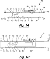
- FIG. 1A and 1B show longitudinal sectional schematic views of flow measurement apparatus 10 according to a first embodiment of the invention.
- the flow measurement apparatus 10 comprises a meter body 11 having a throughbore 11a with a fluid flow path 12 through which fluid is configured to flow.
- the apparatus 10 is configured to be installed and/or connected in a pipeline structure.
- Flanges 13 are located at the ends of the meter body 11 and are configured to be secured to a pipeline structure (not shown) via bolts or any other affixing manner such as welding if the material is suitable. Seals 19 are provided between the flange sections 13 and the fluid flow path 12
- a flow displacement member 14 is centrally disposed in the fluid flow path 12 and suspended from the meter body 11 via a support 16.
- the flow displacement member 14 is configured to introduce a pressure difference between the fluid upstream of the displacement member 14 and the fluid downstream.
- the profile shape of the displacement member is configured to induce a pressure drop in the fluid as it passes over the displacement member in the fluid flow path.
- the displacement member 14 comprises a diverging cone section 14a and a converging cone section 14b. This is a one example and alternative shaped displacement members suitable for creating a pressure differential in the fluid may be used.
- the flow displacement member 14 is manufactured from a flat plate, which is rolled and welded to produce a hollow rolled flat plate conical shape. This rolled plate cone is configured to be less likely to vibrate during flowing conditions.
- the flow displacement member may be machined from solid material.
- the flow displacement member may optionally be supported by an additional support member 16a to reduce vibration of the flow displacement member during fluid flow.
- the flow measurement apparatus 10 has a first pressure outlet 20 and a second pressure outlet 22.
- the first pressure outlet 20 is configured to be in fluid communication with the fluid flow path 12 at a position upstream of the flow displacement member.
- the second pressure outlet 22 is connected to an interior passageway 24 which extends through the flow displacement member 14 and the support member 16.
- the second pressure outlet 22 is configured to be in fluid communication with the fluid flow path 12 at a position downstream of the flow displacement member via the interior passageway of the flow displacement member 14 and the support member 16.
- the sleeve 30 has an outer diameter and the inner diameter.
- the sleeve is dimensioned such that it is able to slide axially within the inner diameter of the meter body throughbore 11a.
- annular sleeve 30 is located in a first position which is at its outermost extended position from the displacement member 14. In this first position the flow area of the fluid is defined by the peripheral edge 45 of the displacement member and the inner diameter of the throughbore 11a.
- the flow measurement range of the apparatus depends on the beta ratio value of the apparatus.
- the beta ratio value is the ratio of the diameter of the peripheral edge of flow displacement member and the inner diameter of the throughbore 11a.
- the beta ratio value is the ratio of the diameter of the peripheral edge of flow displacement member and the inner diameter of the sleeve.
- Each beta ratio value has a corresponding Coefficient of discharge, which is used along with the measured parameters of Differential Pressure, Flowing Pressure and Temperature to calculate the mass and volume flow rate of the flowing fluid.
- a simple visual pointer may be connected to the sleeve and/or the mechanism to detect where the axial position of the sleeve in the fluid flow path.
- a distance encoder sensor such as an optical rotary encoder may be connected to the sleeve and/or the mechanism. This sensor provides real-time position feedback of the position of the sleeve.
- a graduation scale may be engraved on along the surface of the sleeve to identify the axial position of the sleeve.
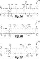
- FIGS 2A to 2I show longitudinal sectional schematic views of flow measurement apparatus 100 according to a second embodiment of the invention.
- the flow measurement apparatus 100 is similar to the apparatus 10 and will be understood from Figures 1A and 1B and the accompanying description.
- flow measurement apparatus 100 has an alternative mechanism used to control the axial movement and positioning of the sleeve.
- the flow measurement apparatus 100 comprises a meter body 111 having a throughbore 111a with a fluid flow path 112 through which fluid is configured to flow.
- An annular sleeve 130 is slidably mounted in the fluid flow path 112.
- the sleeve 130 comprises a series of blind bore holes 132 which are configured to engage locator bolts 108a and 108b.
- the blind holes are arranged on the outer surface of the sleeve 130 and do not extend through the inner surface of the sleeve 130.
- the distance between the series of the blind bore holes 132 is configured to locate the sleeve in predetermined positions within the fluid flow path.
- the entrance throat 134 to the sleeve has a smooth tapered surface.
- the meter body 111 comprises a hatch section 102 with a removable hatch cover 104.
- the hatch cover 104 comprises boreholes 106 through which locator bolts 108a and 108b may extend and securely engage the blind bore holes 132 of the sleeve 130.
- a first high range beta ratio position shown in Figure 2A the sleeve is at the outermost extended position downstream from the displacement member 114.
- the flow area of the fluid and/or the beta ratio of the measurement apparatus is defined by the peripheral edge 145 of the displacement member and the inner diameter of the throughbore 111a.
- the meter is capable of measuring a high range of flow rate.
- the sleeve is located downstream of the displacement member at a distance equal or greater than the diameter of the throughbore 111a and/or the diameter of the pipework to which the apparatus is connected.
- a second low range beta ratio position shown in Figure 2I the sleeve partially encloses the displacement member 114 within the flow path 112.
- the flow area of the fluid and/or the beta ratio of the measurement apparatus is defined by the peripheral edge 145 of the displacement member and the inner diameter of the annular sleeve 130.
- the sleeve 130 has an inner diameter which is smaller than the inner diameter of the throughbore 111a.
- the meter is capable of measuring a low range of flow rate.
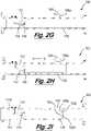
- Figures 2C to 2I show the stages of adjusting the axial position of the sleeve 130 in the flow path from the first to the second position.
- Locator bolt 108a is removed from the hatch section 102 and secured in blind borehole 132b of the sleeve 130.
- the locator bolt 108a is pulled generally in direction show as arrow X to axially move the sleeve axially closer to the displacement member within the fluid flow path as shown in Figure 2D
- the locator bolt 108a is removed from the blind borehole 132b of the sleeve 130 and subsequently secured in blind borehole 132c.
- the locator bolt 108a is again pulled generally in direction show as arrow X to axially move the sleeve within the fluid flow path as shown in Figure 2F .
- the locator bolt 108a is removed from the blind borehole 132c of the sleeve 130 and subsequently secured in blind borehole 132d.
- the locator bolt 108a is pulled in a direction show as arrow X to axially move the sleeve within the fluid flow path as shown in Figure 2H .
- the locator bolt 108a is removed from the blind borehole 132d of the sleeve 130.
- the hatch cover is secured to the hatch section of the fluid flow path.
- Locator bolts 108a and 108b are secured through the boreholes of the hatch cover and are secured in blind boreholes 132c and 132d of the sleeve 130 to secure the sleeve in the second position.
- a potentiometer or magnetic position sensor may be used to accurately determine the position of sleeve within the flow path.
- a graduation scale may be engraved along the surface of the sleeve to identify the axial position of the sleeve within the fluid flow path and/or relative to the displacement member. The graduation scale and therefore the axial position of the sleeve may observed through the hatch section 102.
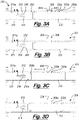
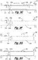
- FIGS 3A to 3K show longitudinal section schematic views of flow measurement apparatus 200 according to a third embodiment of the invention.
- the flow measurement apparatus 200 is similar to the apparatus 10 and will be understood from Figures 1A and 1B and the accompanying description. However, flow measurement apparatus 200 has an alternative sleeve throat section profile.
- the meter body 211 comprises a hatch section 202 with a removable hatch cover 204.
- the hatch cover 204 comprises boreholes 206 through which locator bolts 208 may extend and securely engage the blind bore holes 232 of the sleeve 230.
- the entrance throat 250 of the sleeve comprises a series of relatively short, inward aligned steps 250a and 250b.
- the stepped entrance throat is configured to gradually reduce the inner diameter of sleeve from the inner diameter of the outer step 250a of the entrance throat of the sleeve to the inner diameter of the sleeve.
- three stepped diameters 250a, 250b and the inner diameter of the sleeve can be seen.
- any other number of stepped diameters may be used.
- a first position shown in Figure 3A the sleeve is at the outermost extended position downstream from the displacement member 214.
- the flow area of the fluid is defined by the peripheral edge 245 of the displacement member and the inner diameter of the throughbore 211a.
- the sleeve is located downstream of the displacement member at a distance equal or greater than the diameter of the throughbore 111a and/or the diameter of the pipework to which the apparatus is connected.
- Figures 3A to 3I show the stages of adjusting the beta ratio of the flow measurement apparatus by changing the axial position of the sleeve 230 in the flow path.
- the hatch cover 204 is removed from the hatch section 202 by removing fixing bolts (not shown).
- Locator bolt 208a is removed from the hatch section 202 and secured in blind borehole 232b of the sleeve 230.
- the locator bolt 208a is pulled in a direction show as arrow X to axially move the sleeve to a position closer to the flow displacement member.
- the locator bolt 208a is removed from the blind borehole 232b of the sleeve 230 and subsequently secured in blind borehole 232c.
- the locator bolt 208a is pulled in a direction show as arrow X to axially move the sleeve within the fluid flow path to a second position as shown in Figure 3E .
- the sleeve is positioned around the flow displacement member such that the peripheral edge 245 of the displacement member and the inner diameter of the first step 250a of the throat section of the annular sleeve 230 define flow area of the fluid.
- the first step 250a has an inner diameter which is smaller than the inner diameter of the throughbore 211a. This means that the beta ratio of the measurement apparatus has been reduced when the sleeve is moved from the first position as shown in Figure 3A to the second position as shown in Figure 3E .
- the locator bolt 208a is removed from the blind borehole 232c of the sleeve 230.
- the hatch cover is secured to the hatch section.
- Locator bolts 208a and 208b are secured through the boreholes of the hatch cover and are secured in blind boreholes 232c and 232e of the sleeve 230 to secure the sleeve in this second position.
- the hatch cover 204 is removed from the hatch section 202.
- Locator bolt 208a is removed from the hatch section 202 and secured in blind borehole 232d.
- the locator bolt 208a is pulled in a general direction show as arrow X to axially move the sleeve within the fluid flow path from a second position to a third position.
- the sleeve is positioned around the flow displacement member such that the peripheral edge 245 of the displacement member and the inner diameter of the second step 250b of the throat section of the annular sleeve define a flow area for the fluid.
- the second step 250b has an inner diameter which is smaller than the inner diameter of the first step 250a of the throat section of the sleeve. This means that the beta ratio of the measurement apparatus has been reduced when the sleeve is moved from the second position to a third position.
- the locator bolt 208a is removed from the blind borehole 232c of the sleeve 230.
- the hatch cover 204 is secured to the hatch section 202.
- Locator bolts 208a and 208b are secured through the boreholes of the hatch cover and are secured in blind boreholes 232d and 232f of the sleeve 230 to secure the sleeve in this third position.
- the hatch cover 204 is removed from the hatch section 202.
- Locator bolt 208a is removed from the hatch section 202 and secured in blind borehole 232e.
- the locator bolt 208a is pulled in a direction show as arrow X to axially move the sleeve within the fluid flow path from a third position to a fourth position.
- the sleeve is positioned around the flow displacement member such that the peripheral edge 245 of the displacement member and the inner diameter of the sleeve define a flow area for the fluid.
- the inner diameter of the sleeve has a diameter which is smaller than the inner diameter of the second step 250b of the throat section of the sleeve. This means that the beta ratio of the measurement apparatus has been reduced when the sleeve is moved from the third position to the fourth position.
- An externally mounted resistor or magnetic type position indicator may be used to accurately indicate the position of the sleeve in the fluid flow path.
- an externally mounted resistor may be configured to provide a different resistance reading when the sleeve is located in each of the first to fourth positions.
- the resistor may be configured to have a resistance reading of between 1 and 1.5 Ohms when the sleeve is located in the first position where the flow area of the fluid is defined by the peripheral edge 245 of the displacement member and the inner diameter of the meter body throughbore 211a.
- the resistor may be configured to have a resistance reading of between 2.0 to 2.5 Ohms when the sleeve is located in the second position where the sleeve is positioned around the flow displacement member such that the peripheral edge 245 of the displacement member and the inner diameter of the first step 250a of the throat section of the annular sleeve 230 define flow area of the fluid.
- the resistor may be configured to have a resistance reading of between 4.0 to 4.5 Ohms when the sleeve is positioned around the flow displacement member such that the peripheral edge 245 of the displacement member and the inner diameter of the sleeve define a flow area for the fluid.
- the control unit may be configured to ignore flow readings when the sleeve is located midway between the any of the predetermined first to fourth positions and only measure flow readings when positioned at the first to fourth positions. Therefore, reading will only be measured if the resistor reading is between 1 and 1.5 Ohms, 2 and 2.5 Ohms, 3 and 3.5 Ohms, 4 and 4.5 Ohms and will be ignored at all other resistance levels to mitigate inaccurate measurements when the sleeve is in one of the correct positions.
- the above resistance readings are provided as an example and alternative resistor readings and/or settings may be used.
- the flow measurement apparatus 300 comprises a meter body 311 having a throughbore 311a with a fluid flow path 312 through which fluid is configured to flow.
- the flow path 312 comprises a hatch section 302 through which a coupling 320 of an actuator arm 321 extends.
- the sleeve 330 is connected to the coupling 320 such that activation of the actuator arm 321 axially moves the sleeve axially within the fluid flow path.
- the first pressure port 402 and the first differential fluid area 404 are operable to function as a pressure activated piston to move the sleeve 430 in a first direction generally shown as arrow Y.
- the second pressure port 404 and the second differential fluid area are operable to function as a pressure activated piston to move the sleeve is a second direction generally shown as arrow Z.
- a pressure source (not shown) is applied to the second pressure port 404.
- the increase in pressure acts on the differential area 408 and moves the annular sleeve axially within fluid flow path to a second position shown in Figure 5B , such that the sleeve partially encloses the displacement member 414 within the flow path 412.
- the flow area of the fluid is defined by the peripheral edge 445 of the displacement member and the inner diameter of the annular sleeve 430.
- the sleeve 430 has an inner diameter which is smaller than the inner diameter of the meter body throughbore 411a. This provides a second beta ratio value for the measurement apparatus which allows a second range of flow rates to be measured.
- FIGS 6A to 6K show longitudinal sectional schematic views of flow measurement apparatus 500 according to a sixth embodiment of the invention.
- the flow measurement apparatus 500 is similar to the apparatus 200 and will be understood from Figures 3A to 3K and the accompanying description.
- flow measurement apparatus 500 has an alternative sleeve throat section profile.
- the flow measurement apparatus 500 comprises a meter body 511 having a throughbore 511a with a fluid flow path 512 through which fluid is configured to flow.
- the sleeve 530 comprises a series of blind bore holes 532 which are configured to engage locator bolts 508.
- the blind bore holes are arranged on the outer surface of the sleeve 530 and do not extend through to the inner surface of the sleeve 530.
- the distance between the series of the blind bore holes 532 is configured to locate the sleeve in predetermined positions within the fluid flow path relative to a displacement member 514.
- the entrance throat 550 to the sleeve is tapered.
- the tapered throat is configured to gradually reduce the inner diameter of sleeve from the inner diameter of the outer edge of the entrance throat of the sleeve to the inner diameter of the sleeve.
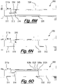
- Figures 6A to 6N show the stages of adjusting the beta ratio of the flow measurement apparatus by changing the axial position of the sleeve 530 in the flow path.
- a hatch cover 504 is removed from a hatch section 502 on the meter body 511 by removing fixing bolts.
- the locator bolt 508a may engage blind boreholes 532a to 532I of the sleeve 530 and may be pulled in a direction show as arrow X to axially move the sleeve 530 within the fluid flow path 512 in a similar manner as described in the description of Figures 3A to 3K .
- the sleeve is moved from the second position to a third position shown in Figure 6H .
- the locator bolt 508a engages blind borehole 532e of the sleeve 530 and is pulled in a direction show as arrow X to axially move the sleeve within the fluid flow path from a second position to a third position.
- the sleeve is positioned around the flow displacement member such that flow area defined by the peripheral edge 545 of the displacement member and the inner diameter of the throat section is smaller than the flow area in the second position as shown in Figure 6H .
- This means that the beta ratio of the measurement apparatus has been reduced when the sleeve is moved from the second position to the third position. The change in the beta ratio allows the measurement apparatus to measure a different flow rate range.
- the hatch cover 504 and locator bolts 508a and 508b may secured through the boreholes and blind boreholes 532d and 532f as shown in Figure 6I .
- the sleeve is moved from the third position to a fourth position shown in Figure 6K .
- the locator bolt 508a engages blind borehole 532f of the sleeve 530 and is pulled in a direction show as arrow X to axially move the sleeve within the fluid flow path from a third position to a fourth position.
- the sleeve is positioned around the flow displacement member such that flow area defined by the peripheral edge 545 of the displacement member and the inner diameter of the throat section is smaller than the flow area in the third position as shown in Figure 6K .
- This means that the beta ratio of the measurement apparatus has been reduced when the sleeve is moved from the third position to the fourth position.
- the hatch cover 504 and locator bolts 508a and 508b may secured through the boreholes and blind boreholes 532e and 532g as shown in Figure 6L .
- the sleeve is moved from the fourth position to a fifth position shown in Figure 6N .
- the locator bolt 508a engages blind borehole 532f of the sleeve 530 and is pulled generally in a direction show as arrow X to axially move the sleeve within the fluid flow path from a fourth position to a fifth position.
- the sleeve is positioned around the flow displacement member such that the peripheral edge 545 of the displacement member and the inner diameter of the sleeve 530 define a flow area of the fluid.
- the inner diameter of the sleeve is smaller than the sleeve throat section as shown in Figure 6N . This means that the beta ratio of the measurement apparatus has been reduced when the sleeve is moved from the fourth position to the fifth position.
- the locator bolt 508a is removed from the blind borehole 532f of the sleeve 530.
- the hatch cover is secured to the hatch section of the meter body.
- Locator bolts 508a and 508b are secured through the boreholes of the hatch cover and are secured in blind boreholes 532e and 532g of the sleeve 530 to secure the sleeve in this fifth position.
- parameters including fluid properties (Step 601), flow pressure levels (Step 602) and temperature levels (Step 603) are measured and communicated to a control unit.
- control unit is able to calculate the fluid base density, flowing density, base compressibility and flowing compressibility of the fluid (Step 604).
- a beta ratio for the measurement device is calculated based on the position of the sleeve within the flow path.
- the precise axial position of the sleeve within the meter body bore flow path is communicated to the control unit where a real time beta ratio is calculated.
- the position of the sleeve may be entered into the control unit manually by the user setting its position or automatically by the position of the sleeve being detected using position detection sensors to determine the sleeve position (Step 606).
- the beta ratio and coefficient of discharge values are calculated from preset tables parameters including inner diameter of the meter body throughbore, inner diameter of the sleeve and/or inner diameter of a sleeve throat section, beta ratio and coefficient of discharge value for the corresponding preset position of the sleeve within the fluid flow path of the meter body (Step 607).
- the control unit displays parameters such as differential pressure readings, pressure readings, temperature, flowing density, flowing compressibility, sleeve position in the meter body fluid flow path, mass and volume flow rate, beta ratio, coefficient of discharge, inner diameter of the meter body throughbore, inner diameter of the sleeve and/or inner diameter of a sleeve throat section for the user to verify that the calculation is being carried correctly (Step 609).
- the control unit activates an alarm if the sleeve is in a position where the control unit cannot accurately determine and/or measure a parameter such as differential pressure readings, pressure readings, temperature, flowing density, flowing compressibility, sleeve position in the meter body fluid flow path, mass and volume flow rate, beta ratio, coefficient of discharge, inner diameter of the meter body throughbore, inner diameter of the sleeve and/or inner diameter of a sleeve throat section (Step 611).
- the alarm will continue to be activated until such time as the sleeve is moved to an acceptable position or the parameter can be accurately determined or measured.
- the sleeve and/or mechanism may be connected to a control unit and/or computer which may be configured to control the positioning of the annular sleeve in response to output flow rates or flow rates ranges.
- the invention provides an apparatus and method for measuring fluid flow rates.
- the apparatus comprises a meter body comprising a throughbore with a fluid flow path and a flow displacement member.
- the apparatus also provides a sleeve slidably mounted within the fluid flow path.
- the sleeve is configured to be movable between at least two axial positions within the fluid flow path to select a predetermined flow rate measurement range for the flow measurement apparatus.
Landscapes
- Physics & Mathematics (AREA)
- Fluid Mechanics (AREA)
- General Physics & Mathematics (AREA)
- Measuring Volume Flow (AREA)
Applications Claiming Priority (2)
| Application Number | Priority Date | Filing Date | Title |
|---|---|---|---|
| GB1509334.7A GB2538805B (en) | 2015-05-29 | 2015-05-29 | Improved flow measurement apparatus and method of use |
| PCT/GB2016/051543 WO2016193681A1 (en) | 2015-05-29 | 2016-05-27 | Improved flow measurement apparatus and method of use |
Publications (2)
| Publication Number | Publication Date |
|---|---|
| EP3304007A1 EP3304007A1 (en) | 2018-04-11 |
| EP3304007B1 true EP3304007B1 (en) | 2022-10-12 |
Family
ID=53677479
Family Applications (1)
| Application Number | Title | Priority Date | Filing Date |
|---|---|---|---|
| EP16733667.6A Active EP3304007B1 (en) | 2015-05-29 | 2016-05-27 | Improved flow measurement apparatus and method of use |
Country Status (8)
| Country | Link |
|---|---|
| US (1) | US10859415B2 (da) |
| EP (1) | EP3304007B1 (da) |
| AU (1) | AU2016272452B2 (da) |
| CA (1) | CA2985283C (da) |
| DK (1) | DK3304007T3 (da) |
| GB (1) | GB2538805B (da) |
| SA (1) | SA517390412B1 (da) |
| WO (1) | WO2016193681A1 (da) |
Families Citing this family (17)
| Publication number | Priority date | Publication date | Assignee | Title |
|---|---|---|---|---|
| CN105865538B (zh) * | 2016-05-25 | 2023-09-05 | 中国大唐集团科学技术研究院有限公司西北分公司 | 风送煤粉流量自动测量装置 |
| EP3524943A4 (en) * | 2017-12-11 | 2019-11-20 | Wuxi Sea Pioneers Technologies Co. Ltd | HUMID GAS FLOW MEASUREMENT DEVICE BASED ON A RADIOACTIVE SOURCE IN THE EXEMPTION THRESHOLDS |
| DE102017012066A1 (de) * | 2017-12-29 | 2019-07-04 | Endress+Hauser Flowtec Ag | Durchflussmessgerät nach dem Wirbelzählerprinzip, Messrohr dafür und Verfahren zum Messen des Durchflusses oder der Strömungsgeschwindigkeit eines Mediums |
| US11920469B2 (en) | 2020-09-08 | 2024-03-05 | Saudi Arabian Oil Company | Determining fluid parameters |
| US11519767B2 (en) | 2020-09-08 | 2022-12-06 | Saudi Arabian Oil Company | Determining fluid parameters |
| US11702896B2 (en) | 2021-03-05 | 2023-07-18 | Weatherford Technology Holdings, Llc | Flow measurement apparatus and associated systems and methods |
| US11644351B2 (en) | 2021-03-19 | 2023-05-09 | Saudi Arabian Oil Company | Multiphase flow and salinity meter with dual opposite handed helical resonators |
| US11913464B2 (en) | 2021-04-15 | 2024-02-27 | Saudi Arabian Oil Company | Lubricating an electric submersible pump |
| US11661805B2 (en) | 2021-08-02 | 2023-05-30 | Weatherford Technology Holdings, Llc | Real time flow rate and rheology measurement |
| US11846531B2 (en) * | 2021-08-27 | 2023-12-19 | Sensia Llc | Ultrasonic flow meter with inner and outer flow channels |
| US11994016B2 (en) | 2021-12-09 | 2024-05-28 | Saudi Arabian Oil Company | Downhole phase separation in deviated wells |
| US12085687B2 (en) | 2022-01-10 | 2024-09-10 | Saudi Arabian Oil Company | Model-constrained multi-phase virtual flow metering and forecasting with machine learning |
| US11761868B1 (en) * | 2022-03-10 | 2023-09-19 | Saudi Arabian Oil Company | Adjustable cone meter with symmetrical sleeve |
| EP4273514B1 (en) * | 2022-05-06 | 2024-09-18 | Abb Schweiz Ag | System and method for determining at least one calculated process parameter of a fluid in a pipe |
| CN116295674A (zh) * | 2023-03-17 | 2023-06-23 | 陕西景特智能科技有限公司 | 气体流量计 |
| US12222268B1 (en) | 2023-07-20 | 2025-02-11 | Weatherford Technology Holdings, Llc | Non-intrusive rheometer for use in well operations |
| CN118424405B (zh) * | 2024-06-29 | 2025-01-17 | 江苏华尔威科技集团有限公司 | 一种具有温度测量报警功能的流量计 |
Citations (1)
| Publication number | Priority date | Publication date | Assignee | Title |
|---|---|---|---|---|
| JPH09218062A (ja) * | 1996-02-13 | 1997-08-19 | Tsukasa Sotsuken:Kk | 可変断面積ベンチュリー式流量計 |
Family Cites Families (16)
| Publication number | Priority date | Publication date | Assignee | Title |
|---|---|---|---|---|
| US3182501A (en) | 1962-05-18 | 1965-05-11 | Bendix Corp | Flow measuring apparatus |
| US3554031A (en) | 1968-06-11 | 1971-01-12 | Gervase Instr Ltd | Flow rate meter |
| GB1274651A (en) * | 1968-06-28 | 1972-05-17 | Atomic Energy Authority Uk | Improvements in or relating to flow measuring devices |
| US4003253A (en) * | 1975-09-08 | 1977-01-18 | Fischer & Porter Co. | Multi-range vortex-shedding flowmeter |
| EP0124666A1 (en) | 1983-05-06 | 1984-11-14 | Harold George Abbey | Fluidic control system including variable venturi |
| US4873873A (en) * | 1988-02-01 | 1989-10-17 | James L. Day Co., Inc. | Air flow metering terminal and control system |
| US5127173A (en) * | 1990-10-12 | 1992-07-07 | Allied-Signal Inc. | Volumetric fluid flowmeter and method |
| DE4229382A1 (de) * | 1992-09-03 | 1994-03-10 | Knorr Bremse Ag | Durchflußmesser zur Bestimmung strömender Medien |
| JP3519136B2 (ja) * | 1994-08-31 | 2004-04-12 | 株式会社司測研 | 可動ベンチュリ管を用いた可変断面積クリティカル・フロー・ベンチュリ管を用いた定流量サンプリング装置 |
| JP2000028407A (ja) * | 1998-07-09 | 2000-01-28 | Honda Motor Co Ltd | 可変ベンチュリーの流量検出機構 |
| DE69937620T2 (de) * | 1998-07-09 | 2008-10-23 | Honda Giken Kogyo K.K. | Verfahren zur Entnahme einer Abgasprobe unter Verwendung eines Durchflussmengenmessers mit veränderbarem Venturiabschnitt |
| WO2009012230A1 (en) * | 2007-07-13 | 2009-01-22 | Mccrometer, Inc. | Two-phase flow meter |
| BRPI1014249A2 (pt) * | 2009-07-13 | 2016-04-12 | Cameron Int Corp | trocador de relação beta dispositivos de medição de fluxo |
| KR101239756B1 (ko) * | 2010-11-25 | 2013-03-06 | 주식회사 하이트롤 | 벤츄리 콘 메타 |
| US7992453B1 (en) * | 2011-01-14 | 2011-08-09 | Cameron International Corporation | Erosion-resistant insert for flow measurement devices |
| US8984961B2 (en) * | 2012-02-21 | 2015-03-24 | Halliburton Energy Services, Inc. | Pressure differential flow meter including a constriction device that can create multiple areas of constriction |
-
2015
- 2015-05-29 GB GB1509334.7A patent/GB2538805B/en active Active
-
2016
- 2016-05-27 EP EP16733667.6A patent/EP3304007B1/en active Active
- 2016-05-27 DK DK16733667.6T patent/DK3304007T3/da active
- 2016-05-27 CA CA2985283A patent/CA2985283C/en active Active
- 2016-05-27 WO PCT/GB2016/051543 patent/WO2016193681A1/en not_active Ceased
- 2016-05-27 AU AU2016272452A patent/AU2016272452B2/en active Active
- 2016-05-27 US US15/573,122 patent/US10859415B2/en active Active
-
2017
- 2017-11-26 SA SA517390412A patent/SA517390412B1/ar unknown
Patent Citations (1)
| Publication number | Priority date | Publication date | Assignee | Title |
|---|---|---|---|---|
| JPH09218062A (ja) * | 1996-02-13 | 1997-08-19 | Tsukasa Sotsuken:Kk | 可変断面積ベンチュリー式流量計 |
Also Published As
| Publication number | Publication date |
|---|---|
| GB2538805A (en) | 2016-11-30 |
| AU2016272452B2 (en) | 2021-08-12 |
| GB2538805B (en) | 2018-06-27 |
| GB201509334D0 (en) | 2015-07-15 |
| WO2016193681A1 (en) | 2016-12-08 |
| US20180128661A1 (en) | 2018-05-10 |
| AU2016272452A1 (en) | 2018-01-18 |
| SA517390412B1 (ar) | 2021-05-27 |
| US10859415B2 (en) | 2020-12-08 |
| CA2985283A1 (en) | 2016-12-08 |
| DK3304007T3 (da) | 2023-01-16 |
| EP3304007A1 (en) | 2018-04-11 |
| CA2985283C (en) | 2023-10-03 |
Similar Documents
| Publication | Publication Date | Title |
|---|---|---|
| EP3304007B1 (en) | Improved flow measurement apparatus and method of use | |
| US10247590B2 (en) | Balancing valve for adjusting the distribution of fluids in multiple pipes | |
| US8561480B2 (en) | Erosion-resistant insert for flow measurement devices | |
| EP3201573B1 (en) | Compound flow measurement probe with an extended measurement range | |
| CN109891201B (zh) | 流体计量器 | |
| KR101550255B1 (ko) | 유량 모니터 부착 압력식 유량 제어 장치와, 이것을 사용한 유체 공급계의 이상 검출 방법 및 모니터 유량 이상 시의 처치 방법 | |
| CA2366964C (en) | Flowmeter calibration system with statistical optimization technique | |
| US8683875B2 (en) | Beta ratio changer for flow measurement devices | |
| EP3535551B1 (en) | Improvements in or relating to the monitoring of fluid flow | |
| CA2317445A1 (en) | Friction flowmeter | |
| US5509434A (en) | Apparatus and method for controlling and metering the flow of gas through a pipeline | |
| US5548990A (en) | Methods and systems for calibrating flow meters | |
| EP4166824B1 (en) | An improved valve assembly | |
| JP2005267572A (ja) | 流量制御の異常判定方法及び装置 | |
| EP3879237B1 (en) | Vortex flowmeter providing extended flow rate measurement | |
| KR101635555B1 (ko) | 유량측정 장치 및 방법 | |
| CN113295395A (zh) | 一种电磁比例阀流量系数测试系统及方法 | |
| US20110302990A1 (en) | Automatic Valve Calibration of a Blown-Film Extrusion Apparatus | |
| EP4521072B1 (de) | Wirkdruckgeber zur messung von strömungen gasförmiger und flüssiger fluide sowie entsprechendes verfahren | |
| TW201231940A (en) | Testing of flow meters | |
| Rudroff | Onsite proving of gas turbine meters | |
| CALLEJAS et al. | Design of characterization system for differential pressure flow meters | |
| Rouss et al. | Determination of Discharge Coefficient for Ball Valves With Calibrated Inserts | |
| Rudroff | ONSITE PROVING OF GAS FLOW METERS | |
| Rouss et al. | Determination of Discharge Coefficient for Ball Valves With Calibrated Inserts |
Legal Events
| Date | Code | Title | Description |
|---|---|---|---|
| STAA | Information on the status of an ep patent application or granted ep patent |
Free format text: STATUS: THE INTERNATIONAL PUBLICATION HAS BEEN MADE |
|
| PUAI | Public reference made under article 153(3) epc to a published international application that has entered the european phase |
Free format text: ORIGINAL CODE: 0009012 |
|
| STAA | Information on the status of an ep patent application or granted ep patent |
Free format text: STATUS: REQUEST FOR EXAMINATION WAS MADE |
|
| 17P | Request for examination filed |
Effective date: 20171218 |
|
| AK | Designated contracting states |
Kind code of ref document: A1 Designated state(s): AL AT BE BG CH CY CZ DE DK EE ES FI FR GB GR HR HU IE IS IT LI LT LU LV MC MK MT NL NO PL PT RO RS SE SI SK SM TR |
|
| AX | Request for extension of the european patent |
Extension state: BA ME |
|
| DAV | Request for validation of the european patent (deleted) | ||
| DAX | Request for extension of the european patent (deleted) | ||
| STAA | Information on the status of an ep patent application or granted ep patent |
Free format text: STATUS: EXAMINATION IS IN PROGRESS |
|
| 17Q | First examination report despatched |
Effective date: 20200708 |
|
| GRAP | Despatch of communication of intention to grant a patent |
Free format text: ORIGINAL CODE: EPIDOSNIGR1 |
|
| STAA | Information on the status of an ep patent application or granted ep patent |
Free format text: STATUS: GRANT OF PATENT IS INTENDED |
|
| INTG | Intention to grant announced |
Effective date: 20210702 |
|
| GRAJ | Information related to disapproval of communication of intention to grant by the applicant or resumption of examination proceedings by the epo deleted |
Free format text: ORIGINAL CODE: EPIDOSDIGR1 |
|
| STAA | Information on the status of an ep patent application or granted ep patent |
Free format text: STATUS: EXAMINATION IS IN PROGRESS |
|
| GRAP | Despatch of communication of intention to grant a patent |
Free format text: ORIGINAL CODE: EPIDOSNIGR1 |
|
| STAA | Information on the status of an ep patent application or granted ep patent |
Free format text: STATUS: GRANT OF PATENT IS INTENDED |
|
| INTC | Intention to grant announced (deleted) | ||
| INTG | Intention to grant announced |
Effective date: 20211130 |
|
| GRAJ | Information related to disapproval of communication of intention to grant by the applicant or resumption of examination proceedings by the epo deleted |
Free format text: ORIGINAL CODE: EPIDOSDIGR1 |
|
| STAA | Information on the status of an ep patent application or granted ep patent |
Free format text: STATUS: EXAMINATION IS IN PROGRESS |
|
| REG | Reference to a national code |
Ref country code: DE Ref legal event code: R079 Ref document number: 602016075591 Country of ref document: DE Free format text: PREVIOUS MAIN CLASS: G01F0001220000 Ipc: G01F0001663000 |
|
| INTC | Intention to grant announced (deleted) | ||
| GRAP | Despatch of communication of intention to grant a patent |
Free format text: ORIGINAL CODE: EPIDOSNIGR1 |
|
| STAA | Information on the status of an ep patent application or granted ep patent |
Free format text: STATUS: GRANT OF PATENT IS INTENDED |
|
| RIC1 | Information provided on ipc code assigned before grant |
Ipc: G01F 1/22 20060101ALI20220412BHEP Ipc: G01F 1/26 20060101ALI20220412BHEP Ipc: G01F 1/32 20060101ALI20220412BHEP Ipc: G01F 1/34 20060101ALI20220412BHEP Ipc: G01F 1/42 20060101ALI20220412BHEP Ipc: G01F 1/44 20060101ALI20220412BHEP Ipc: G01F 1/46 20060101ALI20220412BHEP Ipc: G01F 1/56 20060101ALI20220412BHEP Ipc: G01F 1/58 20060101ALI20220412BHEP Ipc: G01F 1/66 20060101ALI20220412BHEP Ipc: G01F 1/68 20060101ALI20220412BHEP Ipc: G01F 1/84 20060101ALI20220412BHEP Ipc: G01F 1/90 20060101ALI20220412BHEP Ipc: G01F 15/00 20060101ALI20220412BHEP Ipc: G01F 1/663 20220101AFI20220412BHEP |
|
| INTG | Intention to grant announced |
Effective date: 20220504 |
|
| GRAS | Grant fee paid |
Free format text: ORIGINAL CODE: EPIDOSNIGR3 |
|
| GRAA | (expected) grant |
Free format text: ORIGINAL CODE: 0009210 |
|
| STAA | Information on the status of an ep patent application or granted ep patent |
Free format text: STATUS: THE PATENT HAS BEEN GRANTED |
|
| RBV | Designated contracting states (corrected) |
Designated state(s): AL AT BE BG CH CY CZ DE DK EE ES FI FR GR HR HU IE IS IT LI LT LU LV MC MK MT NL NO PL PT RO RS SE SI SK SM TR |
|
| AK | Designated contracting states |
Kind code of ref document: B1 Designated state(s): AL AT BE BG CH CY CZ DE DK EE ES FI FR GR HR HU IE IS IT LI LT LU LV MC MK MT NL NO PL PT RO RS SE SI SK SM TR |
|
| REG | Reference to a national code |
Ref country code: CH Ref legal event code: EP |
|
| REG | Reference to a national code |
Ref country code: DE Ref legal event code: R096 Ref document number: 602016075591 Country of ref document: DE |
|
| REG | Reference to a national code |
Ref country code: IE Ref legal event code: FG4D |
|
| REG | Reference to a national code |
Ref country code: AT Ref legal event code: REF Ref document number: 1524426 Country of ref document: AT Kind code of ref document: T Effective date: 20221115 |
|
| REG | Reference to a national code |
Ref country code: NL Ref legal event code: FP |
|
| REG | Reference to a national code |
Ref country code: DK Ref legal event code: T3 Effective date: 20230112 |
|
| REG | Reference to a national code |
Ref country code: LT Ref legal event code: MG9D |
|
| REG | Reference to a national code |
Ref country code: AT Ref legal event code: MK05 Ref document number: 1524426 Country of ref document: AT Kind code of ref document: T Effective date: 20221012 |
|
| PG25 | Lapsed in a contracting state [announced via postgrant information from national office to epo] |
Ref country code: SE Free format text: LAPSE BECAUSE OF FAILURE TO SUBMIT A TRANSLATION OF THE DESCRIPTION OR TO PAY THE FEE WITHIN THE PRESCRIBED TIME-LIMIT Effective date: 20221012 Ref country code: PT Free format text: LAPSE BECAUSE OF FAILURE TO SUBMIT A TRANSLATION OF THE DESCRIPTION OR TO PAY THE FEE WITHIN THE PRESCRIBED TIME-LIMIT Effective date: 20230213 Ref country code: NO Free format text: LAPSE BECAUSE OF FAILURE TO SUBMIT A TRANSLATION OF THE DESCRIPTION OR TO PAY THE FEE WITHIN THE PRESCRIBED TIME-LIMIT Effective date: 20230112 Ref country code: LT Free format text: LAPSE BECAUSE OF FAILURE TO SUBMIT A TRANSLATION OF THE DESCRIPTION OR TO PAY THE FEE WITHIN THE PRESCRIBED TIME-LIMIT Effective date: 20221012 Ref country code: FI Free format text: LAPSE BECAUSE OF FAILURE TO SUBMIT A TRANSLATION OF THE DESCRIPTION OR TO PAY THE FEE WITHIN THE PRESCRIBED TIME-LIMIT Effective date: 20221012 Ref country code: ES Free format text: LAPSE BECAUSE OF FAILURE TO SUBMIT A TRANSLATION OF THE DESCRIPTION OR TO PAY THE FEE WITHIN THE PRESCRIBED TIME-LIMIT Effective date: 20221012 Ref country code: AT Free format text: LAPSE BECAUSE OF FAILURE TO SUBMIT A TRANSLATION OF THE DESCRIPTION OR TO PAY THE FEE WITHIN THE PRESCRIBED TIME-LIMIT Effective date: 20221012 |
|
| PG25 | Lapsed in a contracting state [announced via postgrant information from national office to epo] |
Ref country code: RS Free format text: LAPSE BECAUSE OF FAILURE TO SUBMIT A TRANSLATION OF THE DESCRIPTION OR TO PAY THE FEE WITHIN THE PRESCRIBED TIME-LIMIT Effective date: 20221012 Ref country code: PL Free format text: LAPSE BECAUSE OF FAILURE TO SUBMIT A TRANSLATION OF THE DESCRIPTION OR TO PAY THE FEE WITHIN THE PRESCRIBED TIME-LIMIT Effective date: 20221012 Ref country code: LV Free format text: LAPSE BECAUSE OF FAILURE TO SUBMIT A TRANSLATION OF THE DESCRIPTION OR TO PAY THE FEE WITHIN THE PRESCRIBED TIME-LIMIT Effective date: 20221012 Ref country code: IS Free format text: LAPSE BECAUSE OF FAILURE TO SUBMIT A TRANSLATION OF THE DESCRIPTION OR TO PAY THE FEE WITHIN THE PRESCRIBED TIME-LIMIT Effective date: 20230212 Ref country code: HR Free format text: LAPSE BECAUSE OF FAILURE TO SUBMIT A TRANSLATION OF THE DESCRIPTION OR TO PAY THE FEE WITHIN THE PRESCRIBED TIME-LIMIT Effective date: 20221012 Ref country code: GR Free format text: LAPSE BECAUSE OF FAILURE TO SUBMIT A TRANSLATION OF THE DESCRIPTION OR TO PAY THE FEE WITHIN THE PRESCRIBED TIME-LIMIT Effective date: 20230113 |
|
| P01 | Opt-out of the competence of the unified patent court (upc) registered |
Effective date: 20230525 |
|
| REG | Reference to a national code |
Ref country code: DE Ref legal event code: R097 Ref document number: 602016075591 Country of ref document: DE |
|
| PG25 | Lapsed in a contracting state [announced via postgrant information from national office to epo] |
Ref country code: SM Free format text: LAPSE BECAUSE OF FAILURE TO SUBMIT A TRANSLATION OF THE DESCRIPTION OR TO PAY THE FEE WITHIN THE PRESCRIBED TIME-LIMIT Effective date: 20221012 Ref country code: RO Free format text: LAPSE BECAUSE OF FAILURE TO SUBMIT A TRANSLATION OF THE DESCRIPTION OR TO PAY THE FEE WITHIN THE PRESCRIBED TIME-LIMIT Effective date: 20221012 Ref country code: EE Free format text: LAPSE BECAUSE OF FAILURE TO SUBMIT A TRANSLATION OF THE DESCRIPTION OR TO PAY THE FEE WITHIN THE PRESCRIBED TIME-LIMIT Effective date: 20221012 Ref country code: CZ Free format text: LAPSE BECAUSE OF FAILURE TO SUBMIT A TRANSLATION OF THE DESCRIPTION OR TO PAY THE FEE WITHIN THE PRESCRIBED TIME-LIMIT Effective date: 20221012 |
|
| PLBE | No opposition filed within time limit |
Free format text: ORIGINAL CODE: 0009261 |
|
| STAA | Information on the status of an ep patent application or granted ep patent |
Free format text: STATUS: NO OPPOSITION FILED WITHIN TIME LIMIT |
|
| PG25 | Lapsed in a contracting state [announced via postgrant information from national office to epo] |
Ref country code: SK Free format text: LAPSE BECAUSE OF FAILURE TO SUBMIT A TRANSLATION OF THE DESCRIPTION OR TO PAY THE FEE WITHIN THE PRESCRIBED TIME-LIMIT Effective date: 20221012 Ref country code: AL Free format text: LAPSE BECAUSE OF FAILURE TO SUBMIT A TRANSLATION OF THE DESCRIPTION OR TO PAY THE FEE WITHIN THE PRESCRIBED TIME-LIMIT Effective date: 20221012 |
|
| 26N | No opposition filed |
Effective date: 20230713 |
|
| PG25 | Lapsed in a contracting state [announced via postgrant information from national office to epo] |
Ref country code: SI Free format text: LAPSE BECAUSE OF FAILURE TO SUBMIT A TRANSLATION OF THE DESCRIPTION OR TO PAY THE FEE WITHIN THE PRESCRIBED TIME-LIMIT Effective date: 20221012 |
|
| REG | Reference to a national code |
Ref country code: CH Ref legal event code: PL |
|
| PG25 | Lapsed in a contracting state [announced via postgrant information from national office to epo] |
Ref country code: MC Free format text: LAPSE BECAUSE OF FAILURE TO SUBMIT A TRANSLATION OF THE DESCRIPTION OR TO PAY THE FEE WITHIN THE PRESCRIBED TIME-LIMIT Effective date: 20221012 |
|
| REG | Reference to a national code |
Ref country code: BE Ref legal event code: MM Effective date: 20230531 |
|
| PG25 | Lapsed in a contracting state [announced via postgrant information from national office to epo] |
Ref country code: MC Free format text: LAPSE BECAUSE OF FAILURE TO SUBMIT A TRANSLATION OF THE DESCRIPTION OR TO PAY THE FEE WITHIN THE PRESCRIBED TIME-LIMIT Effective date: 20221012 Ref country code: LU Free format text: LAPSE BECAUSE OF NON-PAYMENT OF DUE FEES Effective date: 20230527 Ref country code: LI Free format text: LAPSE BECAUSE OF NON-PAYMENT OF DUE FEES Effective date: 20230531 Ref country code: CH Free format text: LAPSE BECAUSE OF NON-PAYMENT OF DUE FEES Effective date: 20230531 |
|
| REG | Reference to a national code |
Ref country code: IE Ref legal event code: MM4A |
|
| PG25 | Lapsed in a contracting state [announced via postgrant information from national office to epo] |
Ref country code: IE Free format text: LAPSE BECAUSE OF NON-PAYMENT OF DUE FEES Effective date: 20230527 |
|
| PG25 | Lapsed in a contracting state [announced via postgrant information from national office to epo] |
Ref country code: IE Free format text: LAPSE BECAUSE OF NON-PAYMENT OF DUE FEES Effective date: 20230527 |
|
| PG25 | Lapsed in a contracting state [announced via postgrant information from national office to epo] |
Ref country code: IT Free format text: LAPSE BECAUSE OF FAILURE TO SUBMIT A TRANSLATION OF THE DESCRIPTION OR TO PAY THE FEE WITHIN THE PRESCRIBED TIME-LIMIT Effective date: 20221012 Ref country code: BE Free format text: LAPSE BECAUSE OF NON-PAYMENT OF DUE FEES Effective date: 20230531 |
|
| PG25 | Lapsed in a contracting state [announced via postgrant information from national office to epo] |
Ref country code: BG Free format text: LAPSE BECAUSE OF FAILURE TO SUBMIT A TRANSLATION OF THE DESCRIPTION OR TO PAY THE FEE WITHIN THE PRESCRIBED TIME-LIMIT Effective date: 20221012 |
|
| PG25 | Lapsed in a contracting state [announced via postgrant information from national office to epo] |
Ref country code: BG Free format text: LAPSE BECAUSE OF FAILURE TO SUBMIT A TRANSLATION OF THE DESCRIPTION OR TO PAY THE FEE WITHIN THE PRESCRIBED TIME-LIMIT Effective date: 20221012 |
|
| PG25 | Lapsed in a contracting state [announced via postgrant information from national office to epo] |
Ref country code: CY Free format text: LAPSE BECAUSE OF FAILURE TO SUBMIT A TRANSLATION OF THE DESCRIPTION OR TO PAY THE FEE WITHIN THE PRESCRIBED TIME-LIMIT; INVALID AB INITIO Effective date: 20160527 |
|
| PG25 | Lapsed in a contracting state [announced via postgrant information from national office to epo] |
Ref country code: HU Free format text: LAPSE BECAUSE OF FAILURE TO SUBMIT A TRANSLATION OF THE DESCRIPTION OR TO PAY THE FEE WITHIN THE PRESCRIBED TIME-LIMIT; INVALID AB INITIO Effective date: 20160527 |
|
| PG25 | Lapsed in a contracting state [announced via postgrant information from national office to epo] |
Ref country code: TR Free format text: LAPSE BECAUSE OF FAILURE TO SUBMIT A TRANSLATION OF THE DESCRIPTION OR TO PAY THE FEE WITHIN THE PRESCRIBED TIME-LIMIT Effective date: 20221012 |
|
| PGFP | Annual fee paid to national office [announced via postgrant information from national office to epo] |
Ref country code: NL Payment date: 20251126 Year of fee payment: 10 |
|
| PGFP | Annual fee paid to national office [announced via postgrant information from national office to epo] |
Ref country code: DE Payment date: 20251128 Year of fee payment: 10 |
|
| PGFP | Annual fee paid to national office [announced via postgrant information from national office to epo] |
Ref country code: DK Payment date: 20251126 Year of fee payment: 10 |
|
| PGFP | Annual fee paid to national office [announced via postgrant information from national office to epo] |
Ref country code: FR Payment date: 20251126 Year of fee payment: 10 |