EP3303912B1 - Lens with elongated radiation pattern - Google Patents
Lens with elongated radiation pattern Download PDFInfo
- Publication number
- EP3303912B1 EP3303912B1 EP16728777.0A EP16728777A EP3303912B1 EP 3303912 B1 EP3303912 B1 EP 3303912B1 EP 16728777 A EP16728777 A EP 16728777A EP 3303912 B1 EP3303912 B1 EP 3303912B1
- Authority
- EP
- European Patent Office
- Prior art keywords
- lens
- trough
- light emitting
- emitting device
- light
- Prior art date
- Legal status (The legal status is an assumption and is not a legal conclusion. Google has not performed a legal analysis and makes no representation as to the accuracy of the status listed.)
- Active
Links
Images


Classifications
-
- F—MECHANICAL ENGINEERING; LIGHTING; HEATING; WEAPONS; BLASTING
- F21—LIGHTING
- F21S—NON-PORTABLE LIGHTING DEVICES; SYSTEMS THEREOF; VEHICLE LIGHTING DEVICES SPECIALLY ADAPTED FOR VEHICLE EXTERIORS
- F21S41/00—Illuminating devices specially adapted for vehicle exteriors, e.g. headlamps
- F21S41/20—Illuminating devices specially adapted for vehicle exteriors, e.g. headlamps characterised by refractors, transparent cover plates, light guides or filters
- F21S41/25—Projection lenses
- F21S41/26—Elongated lenses
-
- F—MECHANICAL ENGINEERING; LIGHTING; HEATING; WEAPONS; BLASTING
- F21—LIGHTING
- F21S—NON-PORTABLE LIGHTING DEVICES; SYSTEMS THEREOF; VEHICLE LIGHTING DEVICES SPECIALLY ADAPTED FOR VEHICLE EXTERIORS
- F21S43/00—Signalling devices specially adapted for vehicle exteriors, e.g. brake lamps, direction indicator lights or reversing lights
- F21S43/20—Signalling devices specially adapted for vehicle exteriors, e.g. brake lamps, direction indicator lights or reversing lights characterised by refractors, transparent cover plates, light guides or filters
- F21S43/26—Refractors, transparent cover plates, light guides or filters not provided in groups F21S43/235 - F21S43/255
-
- F—MECHANICAL ENGINEERING; LIGHTING; HEATING; WEAPONS; BLASTING
- F21—LIGHTING
- F21S—NON-PORTABLE LIGHTING DEVICES; SYSTEMS THEREOF; VEHICLE LIGHTING DEVICES SPECIALLY ADAPTED FOR VEHICLE EXTERIORS
- F21S43/00—Signalling devices specially adapted for vehicle exteriors, e.g. brake lamps, direction indicator lights or reversing lights
- F21S43/20—Signalling devices specially adapted for vehicle exteriors, e.g. brake lamps, direction indicator lights or reversing lights characterised by refractors, transparent cover plates, light guides or filters
- F21S43/2605—Refractors
- F21S43/2621—Refractors characterised by the properties of the light beam shaping surface
- F21S43/26241—Refractors characterised by the properties of the light beam shaping surface diffusing, scattering or spreading
-
- F—MECHANICAL ENGINEERING; LIGHTING; HEATING; WEAPONS; BLASTING
- F21—LIGHTING
- F21S—NON-PORTABLE LIGHTING DEVICES; SYSTEMS THEREOF; VEHICLE LIGHTING DEVICES SPECIALLY ADAPTED FOR VEHICLE EXTERIORS
- F21S43/00—Signalling devices specially adapted for vehicle exteriors, e.g. brake lamps, direction indicator lights or reversing lights
- F21S43/20—Signalling devices specially adapted for vehicle exteriors, e.g. brake lamps, direction indicator lights or reversing lights characterised by refractors, transparent cover plates, light guides or filters
- F21S43/281—Materials thereof; Structures thereof; Properties thereof; Coatings thereof
- F21S43/28135—Structures encapsulating the light source
-
- F—MECHANICAL ENGINEERING; LIGHTING; HEATING; WEAPONS; BLASTING
- F21—LIGHTING
- F21V—FUNCTIONAL FEATURES OR DETAILS OF LIGHTING DEVICES OR SYSTEMS THEREOF; STRUCTURAL COMBINATIONS OF LIGHTING DEVICES WITH OTHER ARTICLES, NOT OTHERWISE PROVIDED FOR
- F21V5/00—Refractors for light sources
- F21V5/04—Refractors for light sources of lens shape
-
- G—PHYSICS
- G02—OPTICS
- G02B—OPTICAL ELEMENTS, SYSTEMS OR APPARATUS
- G02B19/00—Condensers, e.g. light collectors or similar non-imaging optics
- G02B19/0004—Condensers, e.g. light collectors or similar non-imaging optics characterised by the optical means employed
- G02B19/0009—Condensers, e.g. light collectors or similar non-imaging optics characterised by the optical means employed having refractive surfaces only
- G02B19/0014—Condensers, e.g. light collectors or similar non-imaging optics characterised by the optical means employed having refractive surfaces only at least one surface having optical power
-
- G—PHYSICS
- G02—OPTICS
- G02B—OPTICAL ELEMENTS, SYSTEMS OR APPARATUS
- G02B19/00—Condensers, e.g. light collectors or similar non-imaging optics
- G02B19/0033—Condensers, e.g. light collectors or similar non-imaging optics characterised by the use
- G02B19/0047—Condensers, e.g. light collectors or similar non-imaging optics characterised by the use for use with a light source
- G02B19/0061—Condensers, e.g. light collectors or similar non-imaging optics characterised by the use for use with a light source the light source comprising a LED
-
- G—PHYSICS
- G02—OPTICS
- G02B—OPTICAL ELEMENTS, SYSTEMS OR APPARATUS
- G02B3/00—Simple or compound lenses
- G02B3/02—Simple or compound lenses with non-spherical faces
-
- F—MECHANICAL ENGINEERING; LIGHTING; HEATING; WEAPONS; BLASTING
- F21—LIGHTING
- F21W—INDEXING SCHEME ASSOCIATED WITH SUBCLASSES F21K, F21L, F21S and F21V, RELATING TO USES OR APPLICATIONS OF LIGHTING DEVICES OR SYSTEMS
- F21W2102/00—Exterior vehicle lighting devices for illuminating purposes
-
- F—MECHANICAL ENGINEERING; LIGHTING; HEATING; WEAPONS; BLASTING
- F21—LIGHTING
- F21Y—INDEXING SCHEME ASSOCIATED WITH SUBCLASSES F21K, F21L, F21S and F21V, RELATING TO THE FORM OR THE KIND OF THE LIGHT SOURCES OR OF THE COLOUR OF THE LIGHT EMITTED
- F21Y2101/00—Point-like light sources
-
- F—MECHANICAL ENGINEERING; LIGHTING; HEATING; WEAPONS; BLASTING
- F21—LIGHTING
- F21Y—INDEXING SCHEME ASSOCIATED WITH SUBCLASSES F21K, F21L, F21S and F21V, RELATING TO THE FORM OR THE KIND OF THE LIGHT SOURCES OR OF THE COLOUR OF THE LIGHT EMITTED
- F21Y2115/00—Light-generating elements of semiconductor light sources
- F21Y2115/10—Light-emitting diodes [LED]
-
- G—PHYSICS
- G02—OPTICS
- G02B—OPTICAL ELEMENTS, SYSTEMS OR APPARATUS
- G02B3/00—Simple or compound lenses
- G02B2003/0093—Simple or compound lenses characterised by the shape
Definitions
- This invention relates to the field of light emitting devices, and in particular to a lens structure that facilitates the generation of an elongated radiation pattern.
- Lenses are commonly used to alter the shape of the illumination/radiation pattern produced by a light source. Elongated illumination patterns are often required for camera flash lamps, vehicle head lamps, street lighting, and so on.
- USP 7,339,200, "LIGHT-EMITTING DIODE AND VEHICULAR LAMP", issued 4 March 2008 to Amano et al . discloses a lens that provides an elongated illumination pattern for a vehicular lamp by increasing the divergence of light from a light emitting device along one axis.
- the lens includes a concave portion about an optical center of the light emitting device, and a convex portion on either side of the optical center, the convex portions having a larger emission surface than the concave portion.
- the resultant lens is "peanut shaped", the concave portion corresponding to the narrowed center portion of a peanut shell.
- US 2012/218739 Al discloses a lens with an outer area and a concave central area wherein both the central area and the outer area are in the form of a rectangle with rounded corners.
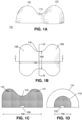
- FIGs. 1A-1D illustrate an example peanut shaped lens 100 that provides an elongated illumination pattern from a single light source that emits a Lambertian radiation pattern.
- FIG. 1A is a perspective view that illustrates the peanut shape having a narrowed center region 110 separating two larger lobes 120. The illustrations are not to scale, and may include exaggerated features for ease of illustration and explanation. In some embodiments, the difference in size/volume between the larger lobes 120 and the smaller center region 110 may be substantially less than illustrated in these figures.
- FIG. 1B illustrates a top view of the peanut shaped lens of FIG. 1A
- FIGs. 1C and 1D illustrate cross-section views taken along views C-C and D-D, respectively, of FIG. 1B
- the view C-C is taken along the long axis 130
- the view D-D is taken along the short axis 140.
- the larger lobes 120 form a convex surface
- the center region 110 forms a concave structure, as viewed along cross-section C-C.
- the cross-section of the center region 110 forms a convex surface.
- Light source 150 may be a semiconductor light emitting device (LED), or a plurality of light emitting devices, and may be arranged within a recess of the lens or situated on or near the lower surface of the lens.
- LED semiconductor light emitting device
- FIGs. 2A and 2B illustrate the light propagation through the lens 100 with respect to each axis 130, 140, respectively.
- the lens 100 includes a concave lens portion 210 and two convex lens portions 220 on either side of the concave lens 210. Each of these lens portions provide an optical axis with respect to the light source 150.
- the concave lens portion 210 provides optical axis 201
- each of the convex lens portions 220 provides an optical axis 202.
- Each optical axis 202 extends from the light source 150 through the center of curvature 205 of the convex len potions 220.
- the concave lens 210 serves to disperse the light emitted from the light source 150 away from the optical axis 201, forming an elongated light emission pattern along the long axis 130.
- Each of the convex lenses 220 serve to converge the light toward its respective optical axis 202, which results in an elongated light emission pattern along the long axis 130.
- the cross section of the lens 100 relative to the short axis 140 forms a convex lens 240.
- the cross section taken along any point on the long axis 130 forms a similarly shaped convex lens, as indicated by the dashed line 240', the size being relative to the height and width of the lens 100 along the long axis 130.
- the convex lens 240 serves to concentrate/ collimate the light from the light source 150, forming a relatively narrow light emission pattern along the short axis 140.
- the convex lens 240' will similarly concentrate/ collimate the light from the light source 150, maintaining a narrower light emission pattern along the short axis 140.
- the overall emission pattern formed by the lens 100 is long in one axis, and narrow in the other axis, forming a substantially rectangular, or oval illumination pattern.
- the complex shape of the lens 100 introduces interdependencies between the parameters in each dimension. For example, if a wider illumination pattern is desired relative to the short axis ( FIG. 2B ), the radius of curvature of the convex lens 240 may need to be decreased. This change of shape of the lens 240 may limit the feasible shapes of the lenses 220. Constraints on the physical size of the lens as well as methods of forming a suitable mold may also limit the shape of the lens.
- a lens that provides an elongated illumination pattern that allows for greater independence with regard to the shape of the illumination pattern in each axis. It would be advantageous, for example, to provide a lens that provides a substantially rectangular or oval illumination pattern with greater independence of control of each dimension of the rectangle/oval.
- an elongated lens is formed with an elongated trough along the long axis on the light emitting surface of the lens.
- the elongated lens may include a curved wall about its perimeter, and a smooth transition between the curved wall and the trough.
- the trough may include a concave shape along both the long axis and the short axis, although the radius of curvature of the concave shape may differ between the long and short axes.
- the eccentricity of the illumination pattern may be controlled by the size of the trough and these radii of curvature.
- a light emitting device may be formed by providing a light emitting element and an elongated lens having a short axis, a long axis, and an upper surface through which desired light from the light emitting element is emitted; wherein the upper surface of the lens includes a trough that extends along the long axis, and a perimeter of the lens includes a curved wall.
- the trough may be symmetric about the short axis and/or the long axis with respect to an optical axis of the light emitting element. There may be a smooth transition joining the trough to the curved wall, and at least a portion of the curved wall may be reflective.
- the lower surface of the trough may have a curvature along the short axis that differs from a curvature along the long axis, and may have a perimeter that is substantially oval.
- the perimeter of the lens may be substantially oval.
- the oval perimeter may also be truncated in the long or short dimension.
- top-emitting light emitting device
- light is assumed to propagate 'up' from a light source then exit from an "upper surface" of the lens, opposite the location of the light source.
- the light source will be a parallelepiped where two of the surfaces will be larger than the other four.
- One of the larger surfaces is designated as the "top” of the light emitting device.
- the four smaller surfaces are the “side surfaces” of the light emitting device which typically emit little or no light. Most of the light is emitted from the "top” of the light emitting device.
- the "upper surface” of the lens is opposite the "top” of the light emitting device.
- Some light may exit the 'side surfaces' of the lens i.e. the portions of the lens opposite the "side surfaces" of the light emitting device.
- the lens of this invention is designed such that a substantial majority of the light from the light source exits the upper surface, in contrast to lenses that are designed to create side-emitting devices that emit a substantial majority of the light through surfaces that are not directly opposite the light source.
- FIGs. 3A-3D illustrate an example light emitting device that includes a light source 350, and an elongated lens in accordance with aspects of this invention.
- the light source 350 may include a single light emitting element, such as a light emitting diode, or multiple light emitting elements.
- the lens may be made of epoxy, silicone, sol-gel, glass or compounds, mixtures, or hybrids thereof.
- the index of refraction at the wavelength of the light source may range from 1.4 to 2.2.
- High index nano-particles with particle sizes less than 100 nm and preferably less than 50 nm dispersed in silicone or a silicate binder may be used to enhance or tune the index of refraction of the lens. Details of the materials can be found in US publication number 20110062469 .
- the light source may be a light emitting diode (LED) with a dimension ranging from 0.2 to 6 mm.
- the lens may have an outside dimension ranging from 1.5 to 50 times the dimension of the LED.
- the aspect ratio of the long to short dimension of the lens can range from 1.25 to 50.
- FIG. 3A illustrates a perspective view of the elongated lens 300.
- FIG. 3B illustrates a top view of the elongated lens 300, through which light is emitted.
- FIG. 3C illustrates a cross section view C-C taken along the long axis 330.
- FIG. 3D illustrates a cross section view D-D taken along the short axis 340.
- the perimeter 305 of the lens 300 is an oval shape with long and short dimensions.
- the perimeter 305 has curved ends along the short dimension and straight lines along the long dimension. In the alternative, not covered by the claims, the straight lines may have a convex curvature so as to form, for example, an elliptical perimeter.
- the lens 300 includes a trough 310 formed in the upper surface 320.
- a trough is defined as a depression in the upper surface 320, along an axis of the lens 300 that is shorter than the length of the lens along that axis.
- the trough 310 may have an oval shape with a long dimension and a short dimension.
- the ratio of the dimension of the trough may be the same or different than the ratio of the long and short dimensions of the lens 300, and the perimeter 315 of the trough 310 may be similar in shape to the perimeter 305 of the lens 300.
- the perimeter 305 of the lens 300 may include a curved wall 325, and there may be a smooth transition 317 between the curved wall 325 and the trough 310.
- the trough 310 may include curved surfaces 316.
- upper surface 320 is used herein to refer to the surface of trough 310, the surface of curved portions 316 and 317, and the surface of the curved portion of the curved wall 325, collectively the surface of the lens 300 emitting the desired light.
- the lens 300 includes a base 326, which may include a recess for receiving the light source 350; alternatively, the light source 350 may be flush with the base or slightly below the base 326.
- Light source 350 may include a reflector, a reflector cup, or a reflector ring.
- the lens 300 may be formed via a mold that provides the shapes of the lens 300, including the trough 310. Other techniques for forming the lens 300 are feasible, including milling the trough 310 out of a preformed elongated lens.
- the trough 310 introduces a lower elevation of the lens 300 at or near the optical axis 301, and a higher elevation on the upper surface 320 of the lens 300.
- a lower surface 315 of the trough 310 may be nearly flat near the optical axis 301, then curves upward 316 toward the higher elevation of the upper surface 320.
- This substantially flat region 315C may introduce more loss of the light emitted by the light source 350 than a more sharply shaped convex region.
- Light striking the flatter region 315C of the depression 310 at greater than a critical angle will be totally internally reflected (TIR) away from the region 315C, thereby increasing the likelihood of the light being absorbed in the device.
- the lower surface 315 of the trough 310 along the short axis 340 provides a concave shape 315D, which also disperses light from the light source 350, but not as far spatially because the convex lobes 320 are more closely spaced along the short axis 340 than for the long axis 330.
- the degree of dispersion of the light in the center region of the lens 300 is determined by the shape (length, width, depth, shape) of the trough 310, including the radius of curvature of the lower surface 315 along each axis 330, 340.
- the surface 315 along the cross-section C-C includes three radii of curvature, a radius of curvature for each of the curved portions 316, and a radius of curvature for the center portion 315C, which may be very large.
- the surface 315 along the cross section D-D includes the radius of curvature of concave portion 315D.
- the degree of dispersion will be greater along the long axis 330, and the total internal reflection at the surfaces 316 may augment the illumination intensity at angles farther from the optical axis 301.
- FIGs. 4A-4B illustrate the propagation of light through the lens 300 relative to the long axis 330 and short axis 340, respectively.
- the cross section shape along the long axis 330 comprises a concave lens 410A and two convex lens portions 420.
- the concave lens portion 410A will disperse the light away from the optical axis 401, albeit to a lesser extent than it would if the convex lens portions 420 were more widely spaced apart.
- the two convex lens portions 420 converge the light toward their corresponding optical axes 402.
- the overall effect of the lens portions 410A, 420 is an elongation of the illumination pattern along the long axis 330.
- the extent of the elongation may be controlled by the orientation of the optical axes 402, the centers of curvature 405, as well as the radii of curvature for each of the lens portions 410A, 420, and other parameters related to the shape of the profile along the long axis 330.
- the cross section shape along the short axis 340 comprises a concave lens portion 410B and two convex lens portions 440.
- the concave lens portion 410A FIG. 4A
- the concave lens portion 410B are formed by the trough 310 ( FIG. 3 )
- the shape of each lens portion 410A, 410B are substantially independent of each other.
- lens portion 410A is flatter than lens portion 410B, which is continually curved.
- the two convex lens portions 440 of FIG. 4B may differ substantially from the convex lens portions 420 of FIG. 4A .
- the lens portions 440 and 420 are somewhat similar, one of skill in the art will recognize that the surface 320 ( FIG. 3 ) that forms these lens portions 420, 440 need not be uniformly thick around the lens 300, nor uniformly tall.
- illumination analysis programs may be used to determine the appropriate shape for transitioning between such differing shapes.
- the extent and uniformity of the illumination pattern relative to the short axis 340 may be controlled by the orientation of the optical axes 404 of the convex lens portions 440, the centers of curvature 407 of these lenses 440, as well as the radii of curvature for each of the lenses 410B, 440, and other parameters related to the shape of the profile along the short axis 340.
- the particular shape of the trough, as well as the overall shape of the lens will be based on the desired light illumination pattern, as well as the intensity distribution. In some embodiments, for example, it may be desirable to provide uniform intensity near the center of the illumination pattern, tapering off, gradually or more sharply, at a given off-axis angle in each dimension. Conventional light propagation and illumination analysis tools may be used to determine a combination of shapes in each dimension that produces the desired illumination pattern and intensity distribution.
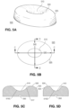
- FIGs. 5A-5D illustrate another example light emitting device that includes an elongated lens in accordance with aspects of this disclosure.
- the lens 500 of FIGs. 5A-5D includes a substantially elliptical profile and substantially elliptical trough 510.
- oval is used to describe an elongated shape having a curved perimeter, including elliptical or other shapes.
- upper surface 520 is used herein to refer to the surface of trough 510, the surface of curved portion 517, and the surface of the curved portion of the curved wall 525, collectively the surface of the lens radiating the desired light.
- the curved wall 525 forms a substantially elliptical perimeter of the lens 500, and the trough 510 also has substantially elliptical perimeter.
- the lower surface 515 provides a substantially continuous concave profile 515C in the long axis 530, and a substantially continuous concave profile 515D in the short axis 540.
- the profile 515C along the long axis 530 may correspondingly provide a more disperse emission pattern from the center of the lens 500 with less loss than the flatter profile 315C of lens 300.
- portions of the lower surface 515, in either axis may be less curved, to increase the intensity of light at the center of the lens 500.
- conventional light propagation analysis tools may be used to determine the shape of the lens, the shape of the trough, the radii of curvature within the trough, as well as the radius of curvature of the curved wall 525, and the radii of curvature forming the smooth transition between the curved wall 525 and the trough 510.
- FIGs. 6-9 illustrate other example elongated lenses with troughs in accordance with aspects of this disclosure.
- Each of these example lenses include features that augment the light emission pattern produced by the lenses conforming to those (300, 500) of FIGs. 3A-3D and FIGs. 5A-5D , as well as other shapes conforming to the principles of this disclosure. These features may serve to provide a more uniform light distribution, for example, by further dispersing light emitted from areas that might otherwise form "bright regions", or “dark regions” on a lens without these features.
- One of skill in the art will recognize that fewer or more features, in different sizes and shapes than illustrated may be used to achieve a desired illumination pattern.
- each feature including its radius of curvature, its position and orientation on the main body of the lens, and the characteristics of the main body of the lens itself will determine how these features may affect the illumination pattern provided by the lens with these features.
- conventional computer-aided-design tools, and/or light propagation analysis tools may be used to determine the effect that the shape and dimensions of each augmentation/feature will have on the resultant light emission pattern produced by the lenses.
- the features 680 are added to a lens 600 that includes a trough 610 that has a perimeter 615 that is similar in shape to the perimeter 605 of the lens 600.; and in FIGs. 7A-7B , the features 780 are added to a lens 700 that has a trough 710 that has a perimeter 715 that is different in shape from the perimeter 705 of the lens 700.
- the lens 700 includes a trough 710 that is shorter and deeper that the trough 610 of lens 600, such that it affects the profile of the lens, as illustrated in FIG. 7B , serving to illustrate that the particular arrangement of the trough with respect to the main body of the lens may vary, depending upon the desired illumination pattern.
- Features 680 and 780 may be convex dimples, each having a surface that is a portion of the surface of sphere or the surface of an ellipse.
- a convex feature 880 is added at the center of the trough 810 of lens 800
- a concave feature (dimple) 980 is added at the center of the trough 910 of lens 900.
- the features 880 or 980 may be a flat surface as well.
- Features 880 and 980 may each have a surface that is a portion of the surface of sphere or the surface of an ellipse.
- the features are illustrated as having sharp edges where they intersect the main body of the lens; one of skill in the art will recognize, however, that a smooth transition from the main body to each feature may provide for a more uniform illumination pattern.
- the invention in an embodiment wherein the lower surface of the lens as well as the upright portions of the curved wall are reflective, thereby reducing absorption losses and/or light propagation in unwanted directions.
- the transition between the convex and concave regions of the lens e.g. 316 of lens 300 in FIG. 3C
- the concave region may also be entirely or partially coated with reflective material to increase total internal reflection.
Landscapes
- Physics & Mathematics (AREA)
- Engineering & Computer Science (AREA)
- General Engineering & Computer Science (AREA)
- General Physics & Mathematics (AREA)
- Optics & Photonics (AREA)
- Lenses (AREA)
- Non-Portable Lighting Devices Or Systems Thereof (AREA)
- Led Device Packages (AREA)
Applications Claiming Priority (2)
| Application Number | Priority Date | Filing Date | Title |
|---|---|---|---|
| US201562169053P | 2015-06-01 | 2015-06-01 | |
| PCT/US2016/033457 WO2016196039A1 (en) | 2015-06-01 | 2016-05-20 | Lens with elongated radiation pattern |
Publications (2)
| Publication Number | Publication Date |
|---|---|
| EP3303912A1 EP3303912A1 (en) | 2018-04-11 |
| EP3303912B1 true EP3303912B1 (en) | 2025-01-08 |
Family
ID=56119756
Family Applications (1)
| Application Number | Title | Priority Date | Filing Date |
|---|---|---|---|
| EP16728777.0A Active EP3303912B1 (en) | 2015-06-01 | 2016-05-20 | Lens with elongated radiation pattern |
Country Status (7)
| Country | Link |
|---|---|
| US (3) | US10677416B2 (enExample) |
| EP (1) | EP3303912B1 (enExample) |
| JP (1) | JP2018519630A (enExample) |
| KR (1) | KR102410450B1 (enExample) |
| CN (1) | CN109073189A (enExample) |
| TW (2) | TWI748951B (enExample) |
| WO (1) | WO2016196039A1 (enExample) |
Families Citing this family (13)
| Publication number | Priority date | Publication date | Assignee | Title |
|---|---|---|---|---|
| US10589210B2 (en) * | 2014-12-30 | 2020-03-17 | Evonik Operations Gmbh | Aluminosilicates and coatings made therefrom for VOC removal |
| KR102410450B1 (ko) | 2015-06-01 | 2022-06-20 | 루미리즈 홀딩 비.브이. | 길쭉한 방사 패턴을 갖는 렌즈 |
| WO2017003090A1 (ko) * | 2015-06-30 | 2017-01-05 | 서울바이오시스 주식회사 | Uv led가 적용된 포충기 |
| JP2019021476A (ja) * | 2017-07-14 | 2019-02-07 | 株式会社エンプラス | 光束制御部材、発光装置、面光源装置、および表示装置 |
| US10851967B2 (en) | 2017-11-17 | 2020-12-01 | Osram Gmbh | Lens, corresponding lighting device, lighting installation and method |
| CN112368665B (zh) | 2018-10-08 | 2024-07-02 | 谷歌有限责任公司 | 显示助理设备中的扬声器组件 |
| KR102119605B1 (ko) * | 2019-06-17 | 2020-06-16 | 주식회사 에이치엘옵틱스 | 엘이디 백라이트 유닛용 비대칭 확산 렌즈 |
| CN114746696B (zh) * | 2019-11-15 | 2025-03-18 | 法雷奥照明公司 | 用于车辆的侧部部分的照明模块 |
| FR3103251B1 (fr) * | 2019-11-15 | 2021-11-12 | Valeo Vision | Module d’éclairage pour partie latérale d’un véhicule |
| KR102341997B1 (ko) | 2019-11-28 | 2021-12-22 | 엘지전자 주식회사 | 반도체 발광 소자를 이용한 차량용 램프 |
| KR102854961B1 (ko) * | 2020-02-11 | 2025-09-04 | 현대자동차주식회사 | 자동차 램프용 확산 렌즈 및 이를 포함하는 자동차 램프 |
| US10995932B1 (en) * | 2020-05-11 | 2021-05-04 | Mitsubishi Electric Research Laboratories, Inc. | Uniform-irradiance extended-source freeforms |
| KR102578782B1 (ko) * | 2022-11-17 | 2023-09-20 | 주식회사 마루라이팅 | 조명장치용 렌즈 및 이를 포함하는 조명장치 |
Citations (8)
| Publication number | Priority date | Publication date | Assignee | Title |
|---|---|---|---|---|
| JPH0668858A (ja) * | 1992-08-18 | 1994-03-11 | Shincron:Kk | 標準光源およびその制御方法 |
| US20050243577A1 (en) * | 2004-04-29 | 2005-11-03 | Moon Jeong M | LED lamp unit |
| US20120218739A1 (en) * | 2006-06-30 | 2012-08-30 | Osram Opto Semiconductors Gmbh, A Corporation Of Germany | Optoelectronic component and illumination device |
| US20120299030A1 (en) * | 2010-02-12 | 2012-11-29 | Osram Opto Semiconductors Gmbh | Optoelectronic semiconductor component, lighting device and lens |
| US20140009944A1 (en) * | 2012-07-04 | 2014-01-09 | Enplas Corporation | Light flux controlling member, light emitting apparatus, surface light source apparatus, and display apparatus |
| CN107013823A (zh) * | 2017-05-05 | 2017-08-04 | 浙江阳光美加照明有限公司 | 一种温控led灯丝及使用该温控led灯丝的led球泡灯 |
| CN107869709A (zh) * | 2017-12-08 | 2018-04-03 | 成都泰和顺信息技术有限公司 | 一种新型led节能灯 |
| US10487988B2 (en) * | 2016-08-15 | 2019-11-26 | Zhejiang Yankon Mega Lighting Co., Ltd. | LED filament and LED light bulb comprising the same |
Family Cites Families (37)
| Publication number | Priority date | Publication date | Assignee | Title |
|---|---|---|---|---|
| KR100616598B1 (ko) | 2004-08-11 | 2006-08-28 | 삼성전기주식회사 | 발광 다이오드 렌즈 및 이를 구비한 백라이트 모듈 |
| WO2006080729A1 (en) | 2004-10-07 | 2006-08-03 | Seoul Semiconductor Co., Ltd. | Side illumination lens and luminescent device using the same |
| JP2007048775A (ja) * | 2005-08-05 | 2007-02-22 | Koito Mfg Co Ltd | 発光ダイオードおよび車両用灯具 |
| KR100649758B1 (ko) | 2005-11-15 | 2006-11-27 | 삼성전기주식회사 | 균일한 광량 분포를 위한 렌즈 및 이를 이용한 발광 장치 |
| JP2009528556A (ja) * | 2006-02-27 | 2009-08-06 | イルミネーション マネジメント ソリューションズ インコーポレイテッド | 幅広ビーム生成のための改良ledデバイス |
| US8669565B2 (en) * | 2006-04-24 | 2014-03-11 | Cree Huizhou Solid State Lighting Company Limited | LED devices with narrow viewing angle and an LED display including same |
| US7918583B2 (en) * | 2006-08-16 | 2011-04-05 | Rpc Photonics, Inc. | Illumination devices |
| JP2008108674A (ja) * | 2006-10-27 | 2008-05-08 | Stanley Electric Co Ltd | Led照明灯具 |
| US8220958B2 (en) * | 2007-04-05 | 2012-07-17 | Koninklijke Philips Electronics N.V. | Light-beam shaper |
| AU2008254676B2 (en) * | 2007-05-21 | 2012-03-22 | Illumination Management Solutions, Inc. | An improved LED device for wide beam generation and method of making the same |
| US9557033B2 (en) * | 2008-03-05 | 2017-01-31 | Cree, Inc. | Optical system for batwing distribution |
| JP5427174B2 (ja) * | 2008-06-23 | 2014-02-26 | パナソニック株式会社 | 発光装置、面発光装置及び表示装置 |
| CN201335320Y (zh) * | 2009-01-21 | 2009-10-28 | 陈哲艮 | 路灯用led光源的透镜以及使用该透镜的路灯 |
| JP4546579B1 (ja) * | 2009-02-12 | 2010-09-15 | パナソニック株式会社 | 照明用レンズ、発光装置、面光源および液晶ディスプレイ装置 |
| CN101846286A (zh) * | 2009-03-23 | 2010-09-29 | 玉晶光电股份有限公司 | Led照明用透镜 |
| US20110062469A1 (en) | 2009-09-17 | 2011-03-17 | Koninklijke Philips Electronics N.V. | Molded lens incorporating a window element |
| CN102032526B (zh) * | 2009-09-30 | 2013-08-07 | 富准精密工业(深圳)有限公司 | 发光二极管模组 |
| US20110235338A1 (en) * | 2010-03-29 | 2011-09-29 | Everlight Electronics Co., Ltd. | Light emitting device and lens thereof |
| CN102297382B (zh) * | 2010-06-25 | 2013-01-02 | 旭丽电子(广州)有限公司 | Led透镜 |
| CN102434813B (zh) * | 2010-09-29 | 2015-08-12 | 欧司朗股份有限公司 | 发光模块以及具有该发光模块的背光照明灯串 |
| US8602604B2 (en) * | 2010-10-14 | 2013-12-10 | Lunera Lighting, Inc. | Extruded wide angle lens for use with a LED light source |
| JP2012129105A (ja) * | 2010-12-16 | 2012-07-05 | Hitachi Consumer Electronics Co Ltd | バックライトユニット、及びそれを用いた液晶表示装置 |
| JP2012216763A (ja) * | 2011-03-25 | 2012-11-08 | Sharp Corp | 発光装置、照明装置、および表示装置 |
| CN102748704A (zh) | 2011-04-19 | 2012-10-24 | 富准精密工业(深圳)有限公司 | 透镜及照明装置 |
| EP2761221B1 (en) * | 2011-09-26 | 2017-10-25 | Musco Corporation | Lighting system having a multi-light source collimator and method of operating such |
| US20130100641A1 (en) * | 2011-10-25 | 2013-04-25 | Marcus Zhang | LED Lamp |
| US10047930B2 (en) * | 2011-12-02 | 2018-08-14 | Seoul Semiconductor Co., Ltd. | Light emitting module and lens |
| KR102009798B1 (ko) * | 2011-12-30 | 2019-08-13 | 엘지디스플레이 주식회사 | 백라이트 유닛 |
| KR101987049B1 (ko) * | 2012-01-10 | 2019-06-10 | 엘지이노텍 주식회사 | 렌즈 유닛 및 발광 장치 |
| DE112013003456T5 (de) * | 2012-03-05 | 2015-05-07 | Seoul Semiconductor Co., Ltd. | Ausleuchtungslinse für Kurzdistanz-Beleuchtung |
| KR101459826B1 (ko) * | 2012-05-30 | 2014-11-13 | 엘지이노텍 주식회사 | 광속 제어 부재 및 이를 포함하는 표시장치 |
| KR102008281B1 (ko) * | 2012-08-16 | 2019-08-07 | 엘지이노텍 주식회사 | 광속 제어 부재, 발광 장치 및 표시 장치 |
| JP6106872B2 (ja) * | 2012-09-01 | 2017-04-05 | ラボ・スフィア株式会社 | バルク型レンズ及びそれを用いた発光体並びに照明装置 |
| TW201435397A (zh) | 2013-03-05 | 2014-09-16 | Hon Hai Prec Ind Co Ltd | 透鏡以及應用該透鏡之發光二極體封裝結構 |
| US8651707B1 (en) * | 2013-03-07 | 2014-02-18 | Ledlink Optics, Inc. | Optical lens for a LED having a quasi-elliptical shape |
| RU2672643C2 (ru) * | 2014-03-28 | 2018-11-16 | Асахи Раббер Инк. | Светораспределительная линза |
| KR102410450B1 (ko) | 2015-06-01 | 2022-06-20 | 루미리즈 홀딩 비.브이. | 길쭉한 방사 패턴을 갖는 렌즈 |
-
2016
- 2016-05-20 KR KR1020177037434A patent/KR102410450B1/ko active Active
- 2016-05-20 US US15/579,105 patent/US10677416B2/en active Active
- 2016-05-20 JP JP2017562595A patent/JP2018519630A/ja active Pending
- 2016-05-20 CN CN201680045363.4A patent/CN109073189A/zh active Pending
- 2016-05-20 EP EP16728777.0A patent/EP3303912B1/en active Active
- 2016-05-20 WO PCT/US2016/033457 patent/WO2016196039A1/en not_active Ceased
- 2016-06-01 TW TW105117249A patent/TWI748951B/zh active
- 2016-06-01 TW TW109112291A patent/TWI749519B/zh active
-
2019
- 2019-05-17 US US16/415,621 patent/US10781997B2/en active Active
-
2020
- 2020-04-21 US US16/854,609 patent/US11022273B2/en active Active
Patent Citations (8)
| Publication number | Priority date | Publication date | Assignee | Title |
|---|---|---|---|---|
| JPH0668858A (ja) * | 1992-08-18 | 1994-03-11 | Shincron:Kk | 標準光源およびその制御方法 |
| US20050243577A1 (en) * | 2004-04-29 | 2005-11-03 | Moon Jeong M | LED lamp unit |
| US20120218739A1 (en) * | 2006-06-30 | 2012-08-30 | Osram Opto Semiconductors Gmbh, A Corporation Of Germany | Optoelectronic component and illumination device |
| US20120299030A1 (en) * | 2010-02-12 | 2012-11-29 | Osram Opto Semiconductors Gmbh | Optoelectronic semiconductor component, lighting device and lens |
| US20140009944A1 (en) * | 2012-07-04 | 2014-01-09 | Enplas Corporation | Light flux controlling member, light emitting apparatus, surface light source apparatus, and display apparatus |
| US10487988B2 (en) * | 2016-08-15 | 2019-11-26 | Zhejiang Yankon Mega Lighting Co., Ltd. | LED filament and LED light bulb comprising the same |
| CN107013823A (zh) * | 2017-05-05 | 2017-08-04 | 浙江阳光美加照明有限公司 | 一种温控led灯丝及使用该温控led灯丝的led球泡灯 |
| CN107869709A (zh) * | 2017-12-08 | 2018-04-03 | 成都泰和顺信息技术有限公司 | 一种新型led节能灯 |
Also Published As
| Publication number | Publication date |
|---|---|
| US11022273B2 (en) | 2021-06-01 |
| JP2018519630A (ja) | 2018-07-19 |
| KR20180014760A (ko) | 2018-02-09 |
| CN109073189A (zh) | 2018-12-21 |
| TW202028650A (zh) | 2020-08-01 |
| WO2016196039A1 (en) | 2016-12-08 |
| EP3303912A1 (en) | 2018-04-11 |
| TW201702520A (zh) | 2017-01-16 |
| US10677416B2 (en) | 2020-06-09 |
| TWI749519B (zh) | 2021-12-11 |
| TWI748951B (zh) | 2021-12-11 |
| US20180172238A1 (en) | 2018-06-21 |
| KR102410450B1 (ko) | 2022-06-20 |
| US20190271451A1 (en) | 2019-09-05 |
| US10781997B2 (en) | 2020-09-22 |
| US20200248887A1 (en) | 2020-08-06 |
Similar Documents
| Publication | Publication Date | Title |
|---|---|---|
| US11022273B2 (en) | Lens with elongated radiation pattern | |
| US7841750B2 (en) | Light-directing lensing member with improved angled light distribution | |
| US9885458B2 (en) | Off-axis collimation optics | |
| US11629843B2 (en) | Optics for chip-on-board road and area lighting | |
| US20140204591A1 (en) | Lens for controlling illuminance distribution and light-emitting diode package including the lens | |
| KR20120019000A (ko) | 광학 렌즈, 이를 구비하는 led 모듈 및 조명 장치 | |
| TWI506229B (zh) | 發光裝置及其透鏡 | |
| TWI479107B (zh) | 發光二極體光分配透鏡及其光源裝置 | |
| CN104235644A (zh) | 照明装置和光导 | |
| US9799810B1 (en) | Light emitting device | |
| US8602577B2 (en) | Side-emitting solid state light source modules with funnel-shaped phosphor surface | |
| JP6689590B2 (ja) | 光束制御部材、発光装置および照明装置 | |
| US10775546B2 (en) | Edge-lit light guide plate with frustoconically-shaped microstructures | |
| US20060202218A1 (en) | Light-emitting diode for decoration | |
| KR101149580B1 (ko) | 엘이디 광원의 광 조정용 확산형 반사체 | |
| US9134005B2 (en) | Illumination apparatus | |
| TW201504579A (zh) | 水晶燈燈源 |
Legal Events
| Date | Code | Title | Description |
|---|---|---|---|
| STAA | Information on the status of an ep patent application or granted ep patent |
Free format text: STATUS: THE INTERNATIONAL PUBLICATION HAS BEEN MADE |
|
| PUAI | Public reference made under article 153(3) epc to a published international application that has entered the european phase |
Free format text: ORIGINAL CODE: 0009012 |
|
| STAA | Information on the status of an ep patent application or granted ep patent |
Free format text: STATUS: REQUEST FOR EXAMINATION WAS MADE |
|
| 17P | Request for examination filed |
Effective date: 20180102 |
|
| AK | Designated contracting states |
Kind code of ref document: A1 Designated state(s): AL AT BE BG CH CY CZ DE DK EE ES FI FR GB GR HR HU IE IS IT LI LT LU LV MC MK MT NL NO PL PT RO RS SE SI SK SM TR |
|
| AX | Request for extension of the european patent |
Extension state: BA ME |
|
| RIN1 | Information on inventor provided before grant (corrected) |
Inventor name: CAMRAS, MICHAEL DAVID |
|
| DAV | Request for validation of the european patent (deleted) | ||
| DAX | Request for extension of the european patent (deleted) | ||
| STAA | Information on the status of an ep patent application or granted ep patent |
Free format text: STATUS: EXAMINATION IS IN PROGRESS |
|
| 17Q | First examination report despatched |
Effective date: 20190326 |
|
| REG | Reference to a national code |
Ref country code: DE Ref legal event code: R079 Free format text: PREVIOUS MAIN CLASS: F21S0008100000 Ipc: G02B0003000000 Ref country code: DE Ref legal event code: R079 Ref document number: 602016090889 Country of ref document: DE Free format text: PREVIOUS MAIN CLASS: F21S0008100000 Ipc: G02B0003000000 |
|
| RIC1 | Information provided on ipc code assigned before grant |
Ipc: F21Y 115/10 20160101ALN20230929BHEP Ipc: F21V 5/04 20060101ALI20230929BHEP Ipc: G02B 19/00 20060101ALI20230929BHEP Ipc: G02B 3/00 20060101AFI20230929BHEP |
|
| GRAP | Despatch of communication of intention to grant a patent |
Free format text: ORIGINAL CODE: EPIDOSNIGR1 |
|
| RIC1 | Information provided on ipc code assigned before grant |
Ipc: F21Y 115/10 20160101ALN20240229BHEP Ipc: F21V 5/04 20060101ALI20240229BHEP Ipc: G02B 19/00 20060101ALI20240229BHEP Ipc: G02B 3/00 20060101AFI20240229BHEP |
|
| STAA | Information on the status of an ep patent application or granted ep patent |
Free format text: STATUS: GRANT OF PATENT IS INTENDED |
|
| RIC1 | Information provided on ipc code assigned before grant |
Ipc: F21Y 115/10 20160101ALN20240305BHEP Ipc: F21V 5/04 20060101ALI20240305BHEP Ipc: G02B 19/00 20060101ALI20240305BHEP Ipc: G02B 3/00 20060101AFI20240305BHEP |
|
| INTG | Intention to grant announced |
Effective date: 20240404 |
|
| GRAJ | Information related to disapproval of communication of intention to grant by the applicant or resumption of examination proceedings by the epo deleted |
Free format text: ORIGINAL CODE: EPIDOSDIGR1 |
|
| STAA | Information on the status of an ep patent application or granted ep patent |
Free format text: STATUS: EXAMINATION IS IN PROGRESS |
|
| INTC | Intention to grant announced (deleted) | ||
| RIC1 | Information provided on ipc code assigned before grant |
Ipc: F21Y 115/10 20160101ALN20240718BHEP Ipc: F21V 5/04 20060101ALI20240718BHEP Ipc: G02B 19/00 20060101ALI20240718BHEP Ipc: G02B 3/00 20060101AFI20240718BHEP |
|
| GRAP | Despatch of communication of intention to grant a patent |
Free format text: ORIGINAL CODE: EPIDOSNIGR1 |
|
| STAA | Information on the status of an ep patent application or granted ep patent |
Free format text: STATUS: GRANT OF PATENT IS INTENDED |
|
| INTG | Intention to grant announced |
Effective date: 20240911 |
|
| GRAS | Grant fee paid |
Free format text: ORIGINAL CODE: EPIDOSNIGR3 |
|
| GRAA | (expected) grant |
Free format text: ORIGINAL CODE: 0009210 |
|
| STAA | Information on the status of an ep patent application or granted ep patent |
Free format text: STATUS: THE PATENT HAS BEEN GRANTED |
|
| AK | Designated contracting states |
Kind code of ref document: B1 Designated state(s): AL AT BE BG CH CY CZ DE DK EE ES FI FR GB GR HR HU IE IS IT LI LT LU LV MC MK MT NL NO PL PT RO RS SE SI SK SM TR |
|
| REG | Reference to a national code |
Ref country code: GB Ref legal event code: FG4D |
|
| REG | Reference to a national code |
Ref country code: CH Ref legal event code: EP |
|
| REG | Reference to a national code |
Ref country code: DE Ref legal event code: R096 Ref document number: 602016090889 Country of ref document: DE |
|
| REG | Reference to a national code |
Ref country code: IE Ref legal event code: FG4D |
|
| P01 | Opt-out of the competence of the unified patent court (upc) registered |
Free format text: CASE NUMBER: APP_1184/2025 Effective date: 20250108 |
|
| REG | Reference to a national code |
Ref country code: LT Ref legal event code: MG9D |
|
| REG | Reference to a national code |
Ref country code: NL Ref legal event code: MP Effective date: 20250108 |
|
| REG | Reference to a national code |
Ref country code: AT Ref legal event code: MK05 Ref document number: 1758686 Country of ref document: AT Kind code of ref document: T Effective date: 20250108 |
|
| PG25 | Lapsed in a contracting state [announced via postgrant information from national office to epo] |
Ref country code: NL Free format text: LAPSE BECAUSE OF FAILURE TO SUBMIT A TRANSLATION OF THE DESCRIPTION OR TO PAY THE FEE WITHIN THE PRESCRIBED TIME-LIMIT Effective date: 20250108 |
|
| PG25 | Lapsed in a contracting state [announced via postgrant information from national office to epo] |
Ref country code: RS Free format text: LAPSE BECAUSE OF FAILURE TO SUBMIT A TRANSLATION OF THE DESCRIPTION OR TO PAY THE FEE WITHIN THE PRESCRIBED TIME-LIMIT Effective date: 20250408 |
|
| PG25 | Lapsed in a contracting state [announced via postgrant information from national office to epo] |
Ref country code: FI Free format text: LAPSE BECAUSE OF FAILURE TO SUBMIT A TRANSLATION OF THE DESCRIPTION OR TO PAY THE FEE WITHIN THE PRESCRIBED TIME-LIMIT Effective date: 20250108 |
|
| PG25 | Lapsed in a contracting state [announced via postgrant information from national office to epo] |
Ref country code: PL Free format text: LAPSE BECAUSE OF FAILURE TO SUBMIT A TRANSLATION OF THE DESCRIPTION OR TO PAY THE FEE WITHIN THE PRESCRIBED TIME-LIMIT Effective date: 20250108 |
|
| PGFP | Annual fee paid to national office [announced via postgrant information from national office to epo] |
Ref country code: DE Payment date: 20250528 Year of fee payment: 10 |
|
| PG25 | Lapsed in a contracting state [announced via postgrant information from national office to epo] |
Ref country code: ES Free format text: LAPSE BECAUSE OF FAILURE TO SUBMIT A TRANSLATION OF THE DESCRIPTION OR TO PAY THE FEE WITHIN THE PRESCRIBED TIME-LIMIT Effective date: 20250108 |
|
| PG25 | Lapsed in a contracting state [announced via postgrant information from national office to epo] |
Ref country code: NO Free format text: LAPSE BECAUSE OF FAILURE TO SUBMIT A TRANSLATION OF THE DESCRIPTION OR TO PAY THE FEE WITHIN THE PRESCRIBED TIME-LIMIT Effective date: 20250408 Ref country code: IS Free format text: LAPSE BECAUSE OF FAILURE TO SUBMIT A TRANSLATION OF THE DESCRIPTION OR TO PAY THE FEE WITHIN THE PRESCRIBED TIME-LIMIT Effective date: 20250508 |
|
| PG25 | Lapsed in a contracting state [announced via postgrant information from national office to epo] |
Ref country code: HR Free format text: LAPSE BECAUSE OF FAILURE TO SUBMIT A TRANSLATION OF THE DESCRIPTION OR TO PAY THE FEE WITHIN THE PRESCRIBED TIME-LIMIT Effective date: 20250108 |
|
| PG25 | Lapsed in a contracting state [announced via postgrant information from national office to epo] |
Ref country code: LV Free format text: LAPSE BECAUSE OF FAILURE TO SUBMIT A TRANSLATION OF THE DESCRIPTION OR TO PAY THE FEE WITHIN THE PRESCRIBED TIME-LIMIT Effective date: 20250108 Ref country code: PT Free format text: LAPSE BECAUSE OF FAILURE TO SUBMIT A TRANSLATION OF THE DESCRIPTION OR TO PAY THE FEE WITHIN THE PRESCRIBED TIME-LIMIT Effective date: 20250508 |
|
| PGFP | Annual fee paid to national office [announced via postgrant information from national office to epo] |
Ref country code: FR Payment date: 20250526 Year of fee payment: 10 |
|
| PG25 | Lapsed in a contracting state [announced via postgrant information from national office to epo] |
Ref country code: BG Free format text: LAPSE BECAUSE OF FAILURE TO SUBMIT A TRANSLATION OF THE DESCRIPTION OR TO PAY THE FEE WITHIN THE PRESCRIBED TIME-LIMIT Effective date: 20250108 Ref country code: GR Free format text: LAPSE BECAUSE OF FAILURE TO SUBMIT A TRANSLATION OF THE DESCRIPTION OR TO PAY THE FEE WITHIN THE PRESCRIBED TIME-LIMIT Effective date: 20250409 |
|
| PG25 | Lapsed in a contracting state [announced via postgrant information from national office to epo] |
Ref country code: AT Free format text: LAPSE BECAUSE OF FAILURE TO SUBMIT A TRANSLATION OF THE DESCRIPTION OR TO PAY THE FEE WITHIN THE PRESCRIBED TIME-LIMIT Effective date: 20250108 |
|
| PG25 | Lapsed in a contracting state [announced via postgrant information from national office to epo] |
Ref country code: SE Free format text: LAPSE BECAUSE OF FAILURE TO SUBMIT A TRANSLATION OF THE DESCRIPTION OR TO PAY THE FEE WITHIN THE PRESCRIBED TIME-LIMIT Effective date: 20250108 |
|
| PG25 | Lapsed in a contracting state [announced via postgrant information from national office to epo] |
Ref country code: SM Free format text: LAPSE BECAUSE OF FAILURE TO SUBMIT A TRANSLATION OF THE DESCRIPTION OR TO PAY THE FEE WITHIN THE PRESCRIBED TIME-LIMIT Effective date: 20250108 |
|
| REG | Reference to a national code |
Ref country code: DE Ref legal event code: R097 Ref document number: 602016090889 Country of ref document: DE |
|
| PG25 | Lapsed in a contracting state [announced via postgrant information from national office to epo] |
Ref country code: DK Free format text: LAPSE BECAUSE OF FAILURE TO SUBMIT A TRANSLATION OF THE DESCRIPTION OR TO PAY THE FEE WITHIN THE PRESCRIBED TIME-LIMIT Effective date: 20250108 |
|
| PG25 | Lapsed in a contracting state [announced via postgrant information from national office to epo] |
Ref country code: EE Free format text: LAPSE BECAUSE OF FAILURE TO SUBMIT A TRANSLATION OF THE DESCRIPTION OR TO PAY THE FEE WITHIN THE PRESCRIBED TIME-LIMIT Effective date: 20250108 Ref country code: CZ Free format text: LAPSE BECAUSE OF FAILURE TO SUBMIT A TRANSLATION OF THE DESCRIPTION OR TO PAY THE FEE WITHIN THE PRESCRIBED TIME-LIMIT Effective date: 20250108 |
|
| PG25 | Lapsed in a contracting state [announced via postgrant information from national office to epo] |
Ref country code: RO Free format text: LAPSE BECAUSE OF FAILURE TO SUBMIT A TRANSLATION OF THE DESCRIPTION OR TO PAY THE FEE WITHIN THE PRESCRIBED TIME-LIMIT Effective date: 20250108 |
|
| PG25 | Lapsed in a contracting state [announced via postgrant information from national office to epo] |
Ref country code: SK Free format text: LAPSE BECAUSE OF FAILURE TO SUBMIT A TRANSLATION OF THE DESCRIPTION OR TO PAY THE FEE WITHIN THE PRESCRIBED TIME-LIMIT Effective date: 20250108 |
|
| PLBE | No opposition filed within time limit |
Free format text: ORIGINAL CODE: 0009261 |
|
| STAA | Information on the status of an ep patent application or granted ep patent |
Free format text: STATUS: NO OPPOSITION FILED WITHIN TIME LIMIT |
|
| REG | Reference to a national code |
Ref country code: CH Ref legal event code: L10 Free format text: ST27 STATUS EVENT CODE: U-0-0-L10-L00 (AS PROVIDED BY THE NATIONAL OFFICE) Effective date: 20251119 |
|
| 26N | No opposition filed |
Effective date: 20251009 |
|
| REG | Reference to a national code |
Ref country code: CH Ref legal event code: H13 Free format text: ST27 STATUS EVENT CODE: U-0-0-H10-H13 (AS PROVIDED BY THE NATIONAL OFFICE) Effective date: 20251223 |
|
| PG25 | Lapsed in a contracting state [announced via postgrant information from national office to epo] |
Ref country code: LU Free format text: LAPSE BECAUSE OF NON-PAYMENT OF DUE FEES Effective date: 20250520 |
|
| PG25 | Lapsed in a contracting state [announced via postgrant information from national office to epo] |
Ref country code: CH Free format text: LAPSE BECAUSE OF NON-PAYMENT OF DUE FEES Effective date: 20250531 |
|
| PG25 | Lapsed in a contracting state [announced via postgrant information from national office to epo] |
Ref country code: IT Free format text: LAPSE BECAUSE OF FAILURE TO SUBMIT A TRANSLATION OF THE DESCRIPTION OR TO PAY THE FEE WITHIN THE PRESCRIBED TIME-LIMIT Effective date: 20250108 |
|
| REG | Reference to a national code |
Ref country code: BE Ref legal event code: MM Effective date: 20250531 |
|
| PG25 | Lapsed in a contracting state [announced via postgrant information from national office to epo] |
Ref country code: MC Free format text: LAPSE BECAUSE OF FAILURE TO SUBMIT A TRANSLATION OF THE DESCRIPTION OR TO PAY THE FEE WITHIN THE PRESCRIBED TIME-LIMIT Effective date: 20250108 |
|
| PGFP | Annual fee paid to national office [announced via postgrant information from national office to epo] |
Ref country code: GB Payment date: 20260304 Year of fee payment: 11 |
|
| PG25 | Lapsed in a contracting state [announced via postgrant information from national office to epo] |
Ref country code: IE Free format text: LAPSE BECAUSE OF NON-PAYMENT OF DUE FEES Effective date: 20250520 |
|
| PG25 | Lapsed in a contracting state [announced via postgrant information from national office to epo] |
Ref country code: BE Free format text: LAPSE BECAUSE OF NON-PAYMENT OF DUE FEES Effective date: 20250531 |