EP3303702B1 - Support de contre-rail adapté pour résister à des efforts transversaux par rapport à une voie ferrée, et ensemble comportant un tel support de contre-rail - Google Patents
Support de contre-rail adapté pour résister à des efforts transversaux par rapport à une voie ferrée, et ensemble comportant un tel support de contre-rail Download PDFInfo
- Publication number
- EP3303702B1 EP3303702B1 EP16729806.6A EP16729806A EP3303702B1 EP 3303702 B1 EP3303702 B1 EP 3303702B1 EP 16729806 A EP16729806 A EP 16729806A EP 3303702 B1 EP3303702 B1 EP 3303702B1
- Authority
- EP
- European Patent Office
- Prior art keywords
- guide rail
- support
- section
- rail support
- counter
- Prior art date
- Legal status (The legal status is an assumption and is not a legal conclusion. Google has not performed a legal analysis and makes no representation as to the accuracy of the status listed.)
- Active
Links
Images



Classifications
-
- E—FIXED CONSTRUCTIONS
- E01—CONSTRUCTION OF ROADS, RAILWAYS, OR BRIDGES
- E01B—PERMANENT WAY; PERMANENT-WAY TOOLS; MACHINES FOR MAKING RAILWAYS OF ALL KINDS
- E01B5/00—Rails; Guard rails; Distance-keeping means for them
- E01B5/18—Guard rails; Connecting, fastening or adjusting means therefor
-
- E—FIXED CONSTRUCTIONS
- E01—CONSTRUCTION OF ROADS, RAILWAYS, OR BRIDGES
- E01B—PERMANENT WAY; PERMANENT-WAY TOOLS; MACHINES FOR MAKING RAILWAYS OF ALL KINDS
- E01B5/00—Rails; Guard rails; Distance-keeping means for them
- E01B5/02—Rails
- E01B5/08—Composite rails; Compound rails with dismountable or non-dismountable parts
-
- E—FIXED CONSTRUCTIONS
- E01—CONSTRUCTION OF ROADS, RAILWAYS, OR BRIDGES
- E01B—PERMANENT WAY; PERMANENT-WAY TOOLS; MACHINES FOR MAKING RAILWAYS OF ALL KINDS
- E01B7/00—Switches; Crossings
- E01B7/20—Safety means for switches, e.g. switch point protectors, auxiliary or guiding rail members
Definitions
- Counter rails are safety features of well-known track devices.
- the counter rails are arranged substantially parallel to a rail of a railroad track, on the inner side of the railway, to prevent the wheel of a railway vehicle traveling on the railways from being detached transversely from the rail in question. This transverse movement of the railway vehicle could damage a switchgear or even cause a derailment.
- the role of the counter rail is therefore to oppose this transverse displacement of the railway vehicle.
- the counter rail is fixed on a counter rail support, itself fixed by its lower face on a track support.
- the counter-rail support must therefore withstand very large transverse forces.
- the current counter-rail supports are designed to withstand a transverse force of the order of 50 kN.
- the evolution of the railway markets towards heavier loads will increase the mechanical stresses to which counter-rail support is subjected in a repetitive manner.
- the document EP 1 253 243 A describes a counter-rail support.
- An object of the invention is therefore to provide a counter-rail support which is mechanically adapted to the evolution of the railway markets, that is to say in particular which can withstand repetitive transversal efforts related to the passage of a railway vehicle, these efforts being able to go up to 100 kN.
- the invention relates to a counter-rail support of the type according to claim 1.
- the invention also relates to an assembly according to claim 7.
- the assembly 1 is for example intended to be part of a track apparatus (not shown) of a railway (not shown).
- the assembly 1 comprises a counter rail 5 extending in a longitudinal direction L of the railroad track, a counter rail support 10, and a track support 15 on which the back rail support is fixed.
- the counter rail 5 is intended to receive forces F exerted in a transverse direction T of the railway by a railway vehicle (not shown) circulating on the railway.
- the counter rail 5 is fixed on the counter rail support 10.
- the transverse direction T is substantially perpendicular to the longitudinal direction L and substantially parallel to the ground.
- a third direction V substantially perpendicular to the longitudinal direction L and to the transverse direction T is defined.
- the third direction V is vertical in the example shown, the floor being substantially horizontal.
- the forces F are applied at the point of application C.
- the point C is for example determined by bringing a plane P 'closer to the counter rail 5, the plane P' being perpendicular to the transverse direction T.
- the track support 15 comprises a subbasement 17, for example made of concrete, and an insulating base 19 located between the counter rail support 10 and the undercarriage in the third direction V.
- the insulating sole 19 makes it possible to prevent the crumbling of the underbody 17 consecutive to micromovements or repeated shocks on the counter-rail support 10.
- the insulating insole 19 is made of polymer material, for example polyamide.
- the insulating sole 19 has a high hardness, advantageously between 50 and 100 Shore A.
- the insulating sole 19 advantageously has a thickness in the third direction V of between 1 and 5 mm, for example about 2 mm.
- the counter-rail support 10 comprises a body 21, and optionally a fastener 23 interposed between the counter rail 5 and the body 21 in the transverse direction T.
- the counter rail support 10 further comprises a plurality of fasteners , including at least a first attachment 25, a second attachment 27 and a third attachment 29, the roles of which will become apparent hereinafter.
- the counter-rail support 10 is advantageously entirely made of metal, metal alloy or composite material.
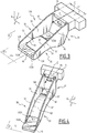
- the body 21 of the counter-rail support 10 comprises a front face 31 in the transverse direction T, a lower face 33 in the third direction V, and two reinforcing ribs 35, 37 (more visible in the variant shown in FIG. figure 3 ).
- the front face 31 is substantially perpendicular to the transverse direction T.
- the front face 31 is in contact with the intermediate piece 23.
- the front face 31 is adapted to receive the forces F transmitted by the rail against 5 and the fastener 23.
- the front face 31 comprises an upper wall 39 facing the counter rail 5 in the transverse direction T, and a lower wall 41 located under the upper wall 39 in the third direction V and connecting the upper wall to the bottom face 33.
- the bottom wall 41 is advantageously devoid of opening, which strengthens the strength of the front face 31.
- the bottom wall 41 forms a non-zero angle with the third direction V.
- the lower face 33 defines a contact plane P with the track support 15, at least when the counter-rail support 10 is not subjected to the forces F.
- the lower face 33 comprises transversely at least a front portion 43 and a part rear 45, both in plane contact with the track support 15 in the contact plane P.
- the front part 43 is fixed on the track support 15 thanks to the second attachment 27.
- the rear part 45 is fixed on the track support 15 by the third attachment 29.
- the second attachment 27 and the third attachment 29 are, for example, lag bolts screwed into the underbody 17.
- the front portion 43 and the rear portion 45 respectively define, in the contact plane P, two contact surfaces 47, 49 distinct and separated by a portion 51 of the contact plane P devoid of any contact with the lower face 33.
- the lower face 33 is not fully in contact with the contact plane P.
- the lower face 33 is in particular not flat.
- contact surfaces 47, 49 are not connected to each other by a continuous contact zone in the contact plane P, or, for example, that each of the contact surfaces 47 , 49 has an outer contour forming a lace in the contact plane P, said laces being separated from each other.
- the reinforcing ribs 35, 37 are substantially perpendicular to the longitudinal direction L, therefore in particular substantially parallel to each other.
- the reinforcing ribs 35, 37 are advantageously located transversely on either side of the lower face 33.
- the reinforcing ribs 35, 37, the front portion 43 of the lower face 33, and the rear portion 45 define a opening 53 in the lower face 33 in the third direction V.
- the opening 53 is for example substantially rectangular in view along the third direction V ( figure 3 ).
- the reinforcing ribs 35, 37 form a bridge connecting the front portion 43 and the rear portion 45 of the lower face 33.
- the reinforcing ribs 35, 37 span the portion 51 of the contact plane P devoid of any contact with the lower face 33.
- each of the reinforcing ribs 35, 37 has an arcuate lower edge 55 transversely connecting the front portion 43 and the rear portion 45.
- Each of the reinforcing ribs 35, 37 also has an upper edge 57 transversely connecting the front face 31 and the rear portion 45.
- the upper edge 57 is for example rectilinear as in the example shown on the figure 1 , or arched with a convexity turned upwards, as in the variant shown on the figure 4 .
- the counter-rail support 10 and the track support 15 define an opening 58 located transversely between the front portion 43 and the rear portion 45 of the lower face 33, under the reinforcing ribs 35, 37.
- the body 21 of the support of the rail-rail 10 comprises only one reinforcing rib extending advantageously according to a mediating plane P '( figure 1 ) of the counter rail support 10.
- the point of application C is for example the point of the counter-rail 5 farthest transversely of the rear portion 45.
- the application point C of the forces F defines a height H in the third direction (V).
- the second attachment 27 and the third attachment 29 are separated transversely by a distance E.
- the ratio of the center distance E divided by the height H is between 0.25 and 10, preferably between 0.75 and 5, even more preferably between 1.0 and 3.
- the contact surface 47 of the front portion 43 of the lower face 33 is in the contact plane P.
- the contact plane P is for example materialized by an upper surface of the insulating sole 19.
- the forces F also result in a bending moment M which is exerted in the vicinity of a point B around the longitudinal direction L.
- the point B is located substantially at the axis of the third attachment 29 in the direction
- the counter-rail support 10 is adapted to withstand the fatigue imposed by the repetitive appearance of the bending moment M.
- the counter rail support 10 is more resistant to fatigue.
- the shear deformation of the insulating base 19 is advantageously less than 0.05 mm under the effect of the forces F.
- the lack of opening in the lower wall 41 of the front face 31 avoids the appearance of stress concentration in the front face.
- the counter-rail support 10 generally withstands the forces F better than the counter-rail supports of the state of the art.
- the counter-rail support 10 is particularly suitable for withstanding forces of up to 100 kN or more.
- the shape of the counter-rail support 10 minimizes the stresses that appear due to the application of the forces F.
- an assembly 100 is described according to a second embodiment of the invention.
- the assembly 100 is similar to the assembly 1 represented on the figure 1 . Similar elements bear the same numerical references and will not be described again. Only the differences will be described in detail below.
- the assembly 100 comprises a body 121 which differs slightly from the body 21.
- the body 121 comprises an arcuate wall 102 connecting the front portion 43 and the rear portion 45. There is therefore no opening equivalent to the opening 53 10.
- the arcuate portion 102 forms a lower flange in the third direction V.
- the arcuate portion 102 spans the portion 51 of the contact plane P devoid of any contact with the lower face 33.
- the arcuate wall 102 has a lower surface 155 itself arcuate, with a convexity facing upwards.
- the lower surface 155 connects transversely the contact surfaces 47, 49.
- the arcuate wall 102 also forms a lower edge of the reinforcing ribs 35, 37.
- the operation of the assembly 100 is similar to that of the assembly 1.
- the arcuate wall 102 no appreciable flexural displacement appears around the longitudinal direction L in the vicinity of the point B. constraints related to the application of the forces F are minimized.
- the counter-rail support 110 and the fasteners are more resistant to the fatigue caused by the repetitive forces F than the prior art counter-brackets and their attachments.
- a counter-rail support 120 is described according to a first variant of the counter-rail support 10 shown in FIG. figure 1 .
- the counter rail support 120 is similar to the counter rail support 10. Also, only the differences will be described in detail below.
- the lower wall 41 of the front face 31 is inclined. This advantageously reduces the stresses in the front face 31.
- Each of the front portion 43 and the rear portion 45 of the lower face 33 comprises two openings 122 adapted to receive two fasteners (not shown) of the body 121 on the track support 15. This reinforces the transverse anchorage of the support against 120
- the upper edge 57 of the reinforcing ribs 35, 37 has a rounding 124 above the rear portion 45 of the lower face 33.
- the attachment piece 23 has a longitudinal extension L1 corresponding substantially to the longitudinal spacing between the reinforcing ribs 35, 37.
- the reinforcing ribs 35, 37 are therefore in the transverse extension of the longitudinal ends of the fastener 23.
- a counter-rail support 130 which constitutes a first variant of the counter-rail support 110 shown in FIG. figure 2 .
- the counter-rail support 130 is similar to the counter-rail support 110.
- the counter-rail support 130 comprises the arcuate lower wall 102 connecting the front portion 43 and the rear portion 45 of the lower face 33.
- the rear portion 45 has two openings 132A, 132B advantageously aligned transversely and allowing for example to receive respectively a tie rod on the track support 15. This reinforces the transverse anchorage of the counter rail support 130.
- the front portion 43 comprises for example a single opening 134 adapted to advantageously receive a retaining bolt.
- a counter-rail support 140 is described according to a second variant of the counter-rail support 10 shown in FIG. figure 1 . Only the differences will be described in detail below.
- the lower edge 55 of the reinforcing ribs 35, 37 is more arcuate.
- Each lower edge 55 has, for example, an apex S making it possible to obtain, when the lateral force is applied, a constant level of mechanical stresses in the counter-rail support while minimizing the maximum value of these stresses and minimizing the weight of the strut. the room.
- the rear portion 45 of the lower face 33 comprises a first portion 142, and a second portion 144 projecting transversely from the first portion to the front portion 43.
- the first portion 142 comprises at least one opening 145 for example adapted to receive the third attachment (not shown).
- the second portion comprises an opening 146 adapted to receive at least one additional attachment, for example a lag bolt (not shown), and defines an additional contact surface 148 in the contact plane P.
- at least one additional attachment for example a lag bolt (not shown)
- the counter-rail support 140 operates in a similar manner to the counter-rail support 10. However, the second portion 144 functions as a hinge about an axis D oriented substantially longitudinally and passing through the point B. Indeed, when the counter-rail support 140 is subjected to F forces related to the passage of the railway vehicle, there may be a slight bending around the axis D.
- the point B is located substantially on the axis of the opening 145, corresponding to the rearmost attachment portion 45 located at the rear in the transverse direction T.
- the lower edge 55 of the reinforcing ribs 35, 37 joins the rear portion 45 at the level of the first portion 142.
- a counter-rail support 150 forming a third variant of the counter-rail support 10 shown on FIG. figure 1 . Only the differences will be described in detail below.
- the reinforcing ribs 35, 37 are not completely parallel to each other.
- the reinforcing ribs 35, 37 respectively comprise a front portion 152 in the transverse direction T, and a rear portion 154.
- the reinforcing ribs 35, 37 are advantageously symmetrical with respect to the median plane P '.
- the front portions 152 of the reinforcing ribs 35, 37 are located transversely at the level of the front portion 43 of the lower face 33 and are advantageously substantially parallel to each other.
- the rear portions 154 of the reinforcing ribs 35, 37 are located in the transverse extension of the front portions 152 of the reinforcing ribs 35, 37 and converge substantially towards one another at a point D situated transversely between the front portion 43 and the rear portion 45 of the lower face 33.
- the front portions 152 and the rear portions 154 of the reinforcing ribs 35, 37 are for example substantially perpendicular to the contact plane P.
- the rear portion 45 has for example two lobes 156, 158 extending on either side of the median plane P 'in the longitudinal direction L.
- the lobes 156, 158 are advantageously symmetrical relative to one another according to the mediator plan P '.
- Each lobe 156 advantageously comprises an opening 159, for example adapted to receive a fastening lag (not shown).
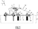
- counter-rail supports 160, 170, 180 respectively forming fourth, fifth and sixth variants of the counter-rail support 10 shown in FIG. figure 1 . Only the differences will be described in detail below.
- the rear portion 45 advantageously defines a stop 162 received in a housing 164 of the track support 15.
- the stop 162 is located transversely on the side opposite to the second attachment 27 with respect to the third attachment 29 (that is to say at the rear of the counter rail support 160).
- the stop 162 protrudes from the contact plane P in the third direction V, downwards.
- the track support 15 forms a stop received in a housing defined by the rear portion 45.
- the stop 162 and the housing 164 cooperate to reduce the recoil of the counter rail support 160 relative to the track support 15 possibly occurring in the transverse direction T when the forces F are applied by the rail vehicle.
- the rear portion 45 defines a stop 172 received in a housing 174 of the track support 15.
- the stop 172 and the housing 174 differ from the abutment 162 and the housing 164 of the counter rail support 160 in that they are located transversely on the other side of the third attachment 29, that is to say that they lie between the first part 43 and the second part 45.
- the stop 172 also serves to limit the possible transverse displacement of the counter-rail support 170 when the forces F are applied.
- the rear portion 45 is not integral with the rest of the body 21, particularly with the reinforcing ribs 35, 37.
- the rear portion 45 defines a stop 182 adapted to oppose a transverse displacement of the reinforcing ribs 35, 37 rearwardly with respect to the contact plane P.
- the rear portion 45 is also fixed on the track support 15 by the third attachment 29 which, in the example shown, is an elastic fastener. This allows an adjustment of the position of the stop 182.
- FIG 10 an assembly 200 forming a third embodiment of the invention is described.
- the assembly 200 is similar to the assembly 1 represented on the figure 1 . Similar elements have the same references and will not be described again. Only the differences will be described in detail below.
- the assembly 200 further comprises a routing core 202, located at the rear of the counter rail support 10, and a spacer 204 extending transversely between the switch core and the counter support. rail.
- the spacer 204 forms a stop 206 adapted to limit any transverse displacement of the counter rail support 10 relative to the track support 15 and the core 202 when the forces F are applied.
- the spacer 204 is fixed to the track support 15, for example by one or more lag screws 208.
- the spacer 204 is in transverse support on the switch core 202.
- the distance between the point of application of the forces F on the counter rail 5 and the switch core 202 defines transversely a gap E1 called protection rating.
- the possible transverse displacement of the counter rail support 10 is further limited.
- insole 19 is optional in assemblies 1, 100 and 200.
Landscapes
- Engineering & Computer Science (AREA)
- Mechanical Engineering (AREA)
- Architecture (AREA)
- Civil Engineering (AREA)
- Structural Engineering (AREA)
- Train Traffic Observation, Control, And Security (AREA)
- Drawers Of Furniture (AREA)
- Bearings For Parts Moving Linearly (AREA)
- Railway Tracks (AREA)
- Connection Of Plates (AREA)
Priority Applications (1)
| Application Number | Priority Date | Filing Date | Title |
|---|---|---|---|
| PL16729806T PL3303702T3 (pl) | 2015-05-29 | 2016-05-27 | Wspornik kierownicy, przystosowany do tego, aby opierał się siłom poprzecznym w stosunku do toru szynowego oraz zespół zawierający taki wspornik kierownicy |
Applications Claiming Priority (2)
| Application Number | Priority Date | Filing Date | Title |
|---|---|---|---|
| FR1554903A FR3036712B1 (fr) | 2015-05-29 | 2015-05-29 | Support de contre-rail adapte pour resister a des efforts transversaux par rapport a une voie ferree, et ensemble comportant un tel support de contre-rail |
| PCT/EP2016/062052 WO2016193165A1 (fr) | 2015-05-29 | 2016-05-27 | Support de contre-rail adapté pour résister à des efforts transversaux par rapport à une voie ferrée, et ensemble comportant un tel support de contre-rail |
Publications (2)
| Publication Number | Publication Date |
|---|---|
| EP3303702A1 EP3303702A1 (fr) | 2018-04-11 |
| EP3303702B1 true EP3303702B1 (fr) | 2019-08-21 |
Family
ID=54066023
Family Applications (1)
| Application Number | Title | Priority Date | Filing Date |
|---|---|---|---|
| EP16729806.6A Active EP3303702B1 (fr) | 2015-05-29 | 2016-05-27 | Support de contre-rail adapté pour résister à des efforts transversaux par rapport à une voie ferrée, et ensemble comportant un tel support de contre-rail |
Country Status (11)
| Country | Link |
|---|---|
| US (1) | US10731302B2 (da) |
| EP (1) | EP3303702B1 (da) |
| AU (1) | AU2016269658B2 (da) |
| DK (1) | DK3303702T3 (da) |
| EA (1) | EA201792379A1 (da) |
| ES (1) | ES2754579T3 (da) |
| FR (1) | FR3036712B1 (da) |
| HU (1) | HUE046947T2 (da) |
| PL (1) | PL3303702T3 (da) |
| PT (1) | PT3303702T (da) |
| WO (1) | WO2016193165A1 (da) |
Families Citing this family (2)
| Publication number | Priority date | Publication date | Assignee | Title |
|---|---|---|---|---|
| FR3036712B1 (fr) * | 2015-05-29 | 2017-07-07 | Vossloh Cogifer | Support de contre-rail adapte pour resister a des efforts transversaux par rapport a une voie ferree, et ensemble comportant un tel support de contre-rail |
| CN111364295A (zh) * | 2020-04-13 | 2020-07-03 | 中国铁建重工集团股份有限公司 | 道岔结构和轨道系统 |
Family Cites Families (15)
| Publication number | Priority date | Publication date | Assignee | Title |
|---|---|---|---|---|
| US1546778A (en) * | 1924-05-09 | 1925-07-21 | Niff Michael J De | Track construction |
| US1560244A (en) * | 1925-07-25 | 1925-11-03 | William P Kalff | Switch-point guard |
| US1628882A (en) * | 1926-08-07 | 1927-05-17 | Ramapo Ajax Corp | Switch-point guard |
| US3026074A (en) * | 1958-05-14 | 1962-03-20 | Bethlehem Steel Corp | Switch point guard rail |
| US3063641A (en) * | 1960-07-08 | 1962-11-13 | Bethlehem Steel Corp | Switch point guard rail |
| US4005839A (en) * | 1975-09-22 | 1977-02-01 | Abex Corporation | Railroad turnouts |
| US4386751A (en) * | 1981-04-06 | 1983-06-07 | Western-Cullen-Hayes, Inc. | Switch point guard |
| AT400861B (de) * | 1988-10-13 | 1996-04-25 | Vae Ag | Rippenplatte mit einem radlenkerstuhl |
| AT405657B (de) * | 1989-06-06 | 1999-10-25 | Vae Ag | Vorrichtung zum festlegen von radlenkern |
| US5115970A (en) * | 1990-09-14 | 1992-05-26 | Bethlehem Steel Corporation | Switch point guard rail |
| US5169064A (en) * | 1990-09-14 | 1992-12-08 | Bethlehem Steel Corporation | Switch point guard rail |
| AT5558U1 (de) * | 2001-04-25 | 2002-08-26 | Vae Eisenbahnsysteme Gmbh | Verfahren zur montage von weichen |
| GB2424439B (en) * | 2005-03-24 | 2008-06-11 | Balfour Beatty Plc | Check rail clamp assembly |
| AT10942U1 (de) * | 2008-12-02 | 2010-01-15 | Vae Eisenbahnsysteme Gmbh | Einrichtung zur direktbefestigung von radlenkern und fahrschienen an betonschwellen |
| FR3036712B1 (fr) * | 2015-05-29 | 2017-07-07 | Vossloh Cogifer | Support de contre-rail adapte pour resister a des efforts transversaux par rapport a une voie ferree, et ensemble comportant un tel support de contre-rail |
-
2015
- 2015-05-29 FR FR1554903A patent/FR3036712B1/fr active Active
-
2016
- 2016-05-27 AU AU2016269658A patent/AU2016269658B2/en not_active Ceased
- 2016-05-27 PT PT167298066T patent/PT3303702T/pt unknown
- 2016-05-27 PL PL16729806T patent/PL3303702T3/pl unknown
- 2016-05-27 EA EA201792379A patent/EA201792379A1/ru unknown
- 2016-05-27 DK DK16729806T patent/DK3303702T3/da active
- 2016-05-27 US US15/577,731 patent/US10731302B2/en active Active
- 2016-05-27 WO PCT/EP2016/062052 patent/WO2016193165A1/fr not_active Ceased
- 2016-05-27 EP EP16729806.6A patent/EP3303702B1/fr active Active
- 2016-05-27 HU HUE16729806A patent/HUE046947T2/hu unknown
- 2016-05-27 ES ES16729806T patent/ES2754579T3/es active Active
Non-Patent Citations (1)
| Title |
|---|
| None * |
Also Published As
| Publication number | Publication date |
|---|---|
| US20180127923A1 (en) | 2018-05-10 |
| PL3303702T3 (pl) | 2020-04-30 |
| ES2754579T3 (es) | 2020-04-20 |
| FR3036712B1 (fr) | 2017-07-07 |
| EP3303702A1 (fr) | 2018-04-11 |
| PT3303702T (pt) | 2019-11-26 |
| EA201792379A1 (ru) | 2018-05-31 |
| AU2016269658A1 (en) | 2017-12-14 |
| WO2016193165A1 (fr) | 2016-12-08 |
| HUE046947T2 (hu) | 2020-03-30 |
| US10731302B2 (en) | 2020-08-04 |
| FR3036712A1 (fr) | 2016-12-02 |
| AU2016269658B2 (en) | 2020-11-05 |
| DK3303702T3 (da) | 2019-11-04 |
Similar Documents
| Publication | Publication Date | Title |
|---|---|---|
| EP3177507B1 (fr) | Structure de véhicule avec renfort entre longeron aluminium et pied avant | |
| FR2761939A1 (fr) | Glissiere pour sieges de vehicules automobiles | |
| EP3096999B1 (fr) | Structure de caisse d'un véhicule automobile avec renforts de répartition des efforts liés à un amortisseur arrière du véhicule | |
| EP3303702B1 (fr) | Support de contre-rail adapté pour résister à des efforts transversaux par rapport à une voie ferrée, et ensemble comportant un tel support de contre-rail | |
| EP1568519B1 (fr) | Plancher pour soufflet d'interconnexion entre deux voitures | |
| EP3996954B1 (fr) | Dispositif de fixation d'un enjoliveur de bord latéral de cadre de porte de véhicule automobile | |
| FR3094326A1 (fr) | Structure arrière de caisse de véhicule automobile comportant des platines de renfort fixées sur les longeronnets avant | |
| WO1990003469A1 (fr) | Dispositif de raccordement entre deux parties de chaussee separees par un joint de dilatation | |
| FR3017362A1 (fr) | Vehicule automobile comprenant une traverse de planche de bord, des bequilles et un tirant constituant en ensemble mecano-soude en aluminium | |
| FR2957105A1 (fr) | Tribune a structure perfectionnee, notamment pour stades | |
| EP1758767B1 (fr) | Bloc projecteur pour véhicule automobile | |
| FR3007377A1 (fr) | Plancher d'assise en tole pour vehicule automobile comportant deux renforts en v. | |
| EP1649116B1 (fr) | Systeme d accrochage de poutre | |
| EP3097000B1 (fr) | Structure de caisse d'un véhicule automobile avec renforts de répartition des efforts liés à un amortisseur arrière du véhicule | |
| FR2985711A1 (fr) | Structure de caisse d'un vehicule automobile | |
| FR2847482A1 (fr) | Planche de glisse sur neige avec plaque a appui lateral | |
| EP2072706A1 (fr) | Plancher comprenant des poutres et des entrevous ainsi qu'une dalle coulée sans couture sur ces poutres et entrevous | |
| EP1972722B1 (fr) | Port d'écluse | |
| EP4169797B1 (fr) | Structure de caisse de voiture de véhicule, notamment ferroviaire | |
| EP1693283A1 (fr) | Structure avant de véhicule automobile | |
| EP3141462B1 (fr) | Structure de vehicule comportent un renfort de planche a talon et vehicule comportant une telle structure | |
| EP1847445B1 (fr) | Structure avant de véhicule automobile et un procédé correspondant | |
| FR2964443A1 (fr) | Element de structure comprenant un longeron creux renforce | |
| EP2613994B1 (fr) | Structure de la partie avant de la caisse d'un vehicule | |
| FR3029851A1 (fr) | Traverse de porte allegee |
Legal Events
| Date | Code | Title | Description |
|---|---|---|---|
| STAA | Information on the status of an ep patent application or granted ep patent |
Free format text: STATUS: THE INTERNATIONAL PUBLICATION HAS BEEN MADE |
|
| PUAI | Public reference made under article 153(3) epc to a published international application that has entered the european phase |
Free format text: ORIGINAL CODE: 0009012 |
|
| STAA | Information on the status of an ep patent application or granted ep patent |
Free format text: STATUS: REQUEST FOR EXAMINATION WAS MADE |
|
| 17P | Request for examination filed |
Effective date: 20171129 |
|
| AK | Designated contracting states |
Kind code of ref document: A1 Designated state(s): AL AT BE BG CH CY CZ DE DK EE ES FI FR GB GR HR HU IE IS IT LI LT LU LV MC MK MT NL NO PL PT RO RS SE SI SK SM TR |
|
| AX | Request for extension of the european patent |
Extension state: BA ME |
|
| DAV | Request for validation of the european patent (deleted) | ||
| DAX | Request for extension of the european patent (deleted) | ||
| GRAP | Despatch of communication of intention to grant a patent |
Free format text: ORIGINAL CODE: EPIDOSNIGR1 |
|
| STAA | Information on the status of an ep patent application or granted ep patent |
Free format text: STATUS: GRANT OF PATENT IS INTENDED |
|
| INTG | Intention to grant announced |
Effective date: 20190204 |
|
| GRAS | Grant fee paid |
Free format text: ORIGINAL CODE: EPIDOSNIGR3 |
|
| GRAA | (expected) grant |
Free format text: ORIGINAL CODE: 0009210 |
|
| STAA | Information on the status of an ep patent application or granted ep patent |
Free format text: STATUS: THE PATENT HAS BEEN GRANTED |
|
| AK | Designated contracting states |
Kind code of ref document: B1 Designated state(s): AL AT BE BG CH CY CZ DE DK EE ES FI FR GB GR HR HU IE IS IT LI LT LU LV MC MK MT NL NO PL PT RO RS SE SI SK SM TR |
|
| REG | Reference to a national code |
Ref country code: GB Ref legal event code: FG4D Free format text: NOT ENGLISH |
|
| REG | Reference to a national code |
Ref country code: CH Ref legal event code: EP |
|
| REG | Reference to a national code |
Ref country code: DE Ref legal event code: R096 Ref document number: 602016019017 Country of ref document: DE |
|
| REG | Reference to a national code |
Ref country code: AT Ref legal event code: REF Ref document number: 1169903 Country of ref document: AT Kind code of ref document: T Effective date: 20190915 |
|
| REG | Reference to a national code |
Ref country code: IE Ref legal event code: FG4D Free format text: LANGUAGE OF EP DOCUMENT: FRENCH |
|
| REG | Reference to a national code |
Ref country code: CH Ref legal event code: NV Representative=s name: MICHELI AND CIE SA, CH |
|
| REG | Reference to a national code |
Ref country code: DK Ref legal event code: T3 Effective date: 20191031 |
|
| REG | Reference to a national code |
Ref country code: PT Ref legal event code: SC4A Ref document number: 3303702 Country of ref document: PT Date of ref document: 20191126 Kind code of ref document: T Free format text: AVAILABILITY OF NATIONAL TRANSLATION Effective date: 20191115 |
|
| REG | Reference to a national code |
Ref country code: SE Ref legal event code: TRGR |
|
| REG | Reference to a national code |
Ref country code: NO Ref legal event code: T2 Effective date: 20190821 |
|
| REG | Reference to a national code |
Ref country code: LT Ref legal event code: MG4D |
|
| REG | Reference to a national code |
Ref country code: NL Ref legal event code: MP Effective date: 20190821 |
|
| PG25 | Lapsed in a contracting state [announced via postgrant information from national office to epo] |
Ref country code: HR Free format text: LAPSE BECAUSE OF FAILURE TO SUBMIT A TRANSLATION OF THE DESCRIPTION OR TO PAY THE FEE WITHIN THE PRESCRIBED TIME-LIMIT Effective date: 20190821 Ref country code: NL Free format text: LAPSE BECAUSE OF FAILURE TO SUBMIT A TRANSLATION OF THE DESCRIPTION OR TO PAY THE FEE WITHIN THE PRESCRIBED TIME-LIMIT Effective date: 20190821 Ref country code: BG Free format text: LAPSE BECAUSE OF FAILURE TO SUBMIT A TRANSLATION OF THE DESCRIPTION OR TO PAY THE FEE WITHIN THE PRESCRIBED TIME-LIMIT Effective date: 20191121 Ref country code: LT Free format text: LAPSE BECAUSE OF FAILURE TO SUBMIT A TRANSLATION OF THE DESCRIPTION OR TO PAY THE FEE WITHIN THE PRESCRIBED TIME-LIMIT Effective date: 20190821 |
|
| PG25 | Lapsed in a contracting state [announced via postgrant information from national office to epo] |
Ref country code: AL Free format text: LAPSE BECAUSE OF FAILURE TO SUBMIT A TRANSLATION OF THE DESCRIPTION OR TO PAY THE FEE WITHIN THE PRESCRIBED TIME-LIMIT Effective date: 20190821 Ref country code: RS Free format text: LAPSE BECAUSE OF FAILURE TO SUBMIT A TRANSLATION OF THE DESCRIPTION OR TO PAY THE FEE WITHIN THE PRESCRIBED TIME-LIMIT Effective date: 20190821 Ref country code: GR Free format text: LAPSE BECAUSE OF FAILURE TO SUBMIT A TRANSLATION OF THE DESCRIPTION OR TO PAY THE FEE WITHIN THE PRESCRIBED TIME-LIMIT Effective date: 20191122 Ref country code: LV Free format text: LAPSE BECAUSE OF FAILURE TO SUBMIT A TRANSLATION OF THE DESCRIPTION OR TO PAY THE FEE WITHIN THE PRESCRIBED TIME-LIMIT Effective date: 20190821 Ref country code: IS Free format text: LAPSE BECAUSE OF FAILURE TO SUBMIT A TRANSLATION OF THE DESCRIPTION OR TO PAY THE FEE WITHIN THE PRESCRIBED TIME-LIMIT Effective date: 20191221 |
|
| REG | Reference to a national code |
Ref country code: HU Ref legal event code: AG4A Ref document number: E046947 Country of ref document: HU |
|
| REG | Reference to a national code |
Ref country code: ES Ref legal event code: FG2A Ref document number: 2754579 Country of ref document: ES Kind code of ref document: T3 Effective date: 20200420 |
|
| PG25 | Lapsed in a contracting state [announced via postgrant information from national office to epo] |
Ref country code: IT Free format text: LAPSE BECAUSE OF FAILURE TO SUBMIT A TRANSLATION OF THE DESCRIPTION OR TO PAY THE FEE WITHIN THE PRESCRIBED TIME-LIMIT Effective date: 20190821 Ref country code: EE Free format text: LAPSE BECAUSE OF FAILURE TO SUBMIT A TRANSLATION OF THE DESCRIPTION OR TO PAY THE FEE WITHIN THE PRESCRIBED TIME-LIMIT Effective date: 20190821 Ref country code: RO Free format text: LAPSE BECAUSE OF FAILURE TO SUBMIT A TRANSLATION OF THE DESCRIPTION OR TO PAY THE FEE WITHIN THE PRESCRIBED TIME-LIMIT Effective date: 20190821 |
|
| PG25 | Lapsed in a contracting state [announced via postgrant information from national office to epo] |
Ref country code: SM Free format text: LAPSE BECAUSE OF FAILURE TO SUBMIT A TRANSLATION OF THE DESCRIPTION OR TO PAY THE FEE WITHIN THE PRESCRIBED TIME-LIMIT Effective date: 20190821 Ref country code: IS Free format text: LAPSE BECAUSE OF FAILURE TO SUBMIT A TRANSLATION OF THE DESCRIPTION OR TO PAY THE FEE WITHIN THE PRESCRIBED TIME-LIMIT Effective date: 20200224 Ref country code: CZ Free format text: LAPSE BECAUSE OF FAILURE TO SUBMIT A TRANSLATION OF THE DESCRIPTION OR TO PAY THE FEE WITHIN THE PRESCRIBED TIME-LIMIT Effective date: 20190821 Ref country code: SK Free format text: LAPSE BECAUSE OF FAILURE TO SUBMIT A TRANSLATION OF THE DESCRIPTION OR TO PAY THE FEE WITHIN THE PRESCRIBED TIME-LIMIT Effective date: 20190821 |
|
| REG | Reference to a national code |
Ref country code: DE Ref legal event code: R097 Ref document number: 602016019017 Country of ref document: DE |
|
| PLBE | No opposition filed within time limit |
Free format text: ORIGINAL CODE: 0009261 |
|
| STAA | Information on the status of an ep patent application or granted ep patent |
Free format text: STATUS: NO OPPOSITION FILED WITHIN TIME LIMIT |
|
| PG2D | Information on lapse in contracting state deleted |
Ref country code: IS |
|
| 26N | No opposition filed |
Effective date: 20200603 |
|
| PG25 | Lapsed in a contracting state [announced via postgrant information from national office to epo] |
Ref country code: SI Free format text: LAPSE BECAUSE OF FAILURE TO SUBMIT A TRANSLATION OF THE DESCRIPTION OR TO PAY THE FEE WITHIN THE PRESCRIBED TIME-LIMIT Effective date: 20190821 |
|
| REG | Reference to a national code |
Ref country code: DK Ref legal event code: EBP Effective date: 20200531 |
|
| PG25 | Lapsed in a contracting state [announced via postgrant information from national office to epo] |
Ref country code: MC Free format text: LAPSE BECAUSE OF FAILURE TO SUBMIT A TRANSLATION OF THE DESCRIPTION OR TO PAY THE FEE WITHIN THE PRESCRIBED TIME-LIMIT Effective date: 20190821 Ref country code: HU Free format text: LAPSE BECAUSE OF NON-PAYMENT OF DUE FEES Effective date: 20200528 |
|
| REG | Reference to a national code |
Ref country code: AT Ref legal event code: UEP Ref document number: 1169903 Country of ref document: AT Kind code of ref document: T Effective date: 20190821 |
|
| REG | Reference to a national code |
Ref country code: BE Ref legal event code: MM Effective date: 20200531 |
|
| PG25 | Lapsed in a contracting state [announced via postgrant information from national office to epo] |
Ref country code: LU Free format text: LAPSE BECAUSE OF NON-PAYMENT OF DUE FEES Effective date: 20200527 |
|
| PG25 | Lapsed in a contracting state [announced via postgrant information from national office to epo] |
Ref country code: PT Free format text: LAPSE BECAUSE OF NON-PAYMENT OF DUE FEES Effective date: 20210324 Ref country code: DK Free format text: LAPSE BECAUSE OF NON-PAYMENT OF DUE FEES Effective date: 20200531 Ref country code: IE Free format text: LAPSE BECAUSE OF NON-PAYMENT OF DUE FEES Effective date: 20200527 |
|
| PG25 | Lapsed in a contracting state [announced via postgrant information from national office to epo] |
Ref country code: BE Free format text: LAPSE BECAUSE OF NON-PAYMENT OF DUE FEES Effective date: 20200531 |
|
| REG | Reference to a national code |
Ref country code: ES Ref legal event code: FD2A Effective date: 20210929 |
|
| PG25 | Lapsed in a contracting state [announced via postgrant information from national office to epo] |
Ref country code: ES Free format text: LAPSE BECAUSE OF NON-PAYMENT OF DUE FEES Effective date: 20200528 |
|
| PG25 | Lapsed in a contracting state [announced via postgrant information from national office to epo] |
Ref country code: MT Free format text: LAPSE BECAUSE OF FAILURE TO SUBMIT A TRANSLATION OF THE DESCRIPTION OR TO PAY THE FEE WITHIN THE PRESCRIBED TIME-LIMIT Effective date: 20190821 Ref country code: CY Free format text: LAPSE BECAUSE OF FAILURE TO SUBMIT A TRANSLATION OF THE DESCRIPTION OR TO PAY THE FEE WITHIN THE PRESCRIBED TIME-LIMIT Effective date: 20190821 |
|
| PG25 | Lapsed in a contracting state [announced via postgrant information from national office to epo] |
Ref country code: MK Free format text: LAPSE BECAUSE OF FAILURE TO SUBMIT A TRANSLATION OF THE DESCRIPTION OR TO PAY THE FEE WITHIN THE PRESCRIBED TIME-LIMIT Effective date: 20190821 |
|
| PG25 | Lapsed in a contracting state [announced via postgrant information from national office to epo] |
Ref country code: PL Free format text: LAPSE BECAUSE OF NON-PAYMENT OF DUE FEES Effective date: 20200527 |
|
| P01 | Opt-out of the competence of the unified patent court (upc) registered |
Effective date: 20230606 |
|
| PGFP | Annual fee paid to national office [announced via postgrant information from national office to epo] |
Ref country code: FI Payment date: 20250423 Year of fee payment: 10 |
|
| PGFP | Annual fee paid to national office [announced via postgrant information from national office to epo] |
Ref country code: DE Payment date: 20250513 Year of fee payment: 10 |
|
| PGFP | Annual fee paid to national office [announced via postgrant information from national office to epo] |
Ref country code: GB Payment date: 20250521 Year of fee payment: 10 |
|
| PGFP | Annual fee paid to national office [announced via postgrant information from national office to epo] |
Ref country code: NO Payment date: 20250425 Year of fee payment: 10 |
|
| PGFP | Annual fee paid to national office [announced via postgrant information from national office to epo] |
Ref country code: FR Payment date: 20250410 Year of fee payment: 10 |
|
| PGFP | Annual fee paid to national office [announced via postgrant information from national office to epo] |
Ref country code: CH Payment date: 20250601 Year of fee payment: 10 |
|
| PGFP | Annual fee paid to national office [announced via postgrant information from national office to epo] |
Ref country code: AT Payment date: 20250423 Year of fee payment: 10 |
|
| PGFP | Annual fee paid to national office [announced via postgrant information from national office to epo] |
Ref country code: TR Payment date: 20250516 Year of fee payment: 10 |
|
| PGFP | Annual fee paid to national office [announced via postgrant information from national office to epo] |
Ref country code: SE Payment date: 20250519 Year of fee payment: 10 |
|
| PG25 | Lapsed in a contracting state [announced via postgrant information from national office to epo] |
Ref country code: IS Free format text: LAPSE BECAUSE OF NON-PAYMENT OF DUE FEES Effective date: 20200224 |
|
| REG | Reference to a national code |
Ref country code: DE Ref legal event code: R081 Ref document number: 602016019017 Country of ref document: DE Owner name: VOSSLOH SWITCH SYSTEMS FRANCE, FR Free format text: FORMER OWNER: VOSSLOH COGIFER, RUEIL MALMAISON, FR |
|
| REG | Reference to a national code |
Ref country code: CH Ref legal event code: R17 Free format text: ST27 STATUS EVENT CODE: U-0-0-R10-R17 (AS PROVIDED BY THE NATIONAL OFFICE) Effective date: 20260320 Ref country code: CH Ref legal event code: R18 Free format text: ST27 STATUS EVENT CODE: U-0-0-R10-R18 (AS PROVIDED BY THE NATIONAL OFFICE) Effective date: 20260320 |
|
| REG | Reference to a national code |
Ref country code: CH Ref legal event code: Y10 Free format text: ST27 STATUS EVENT CODE: U-0-0-Y10-Y00 (AS PROVIDED BY THE NATIONAL OFFICE) Effective date: 20260331 |