EP3302874B1 - Procédé de fabrication d'une aube de turbomachine en tial - Google Patents
Procédé de fabrication d'une aube de turbomachine en tial Download PDFInfo
- Publication number
- EP3302874B1 EP3302874B1 EP16733637.9A EP16733637A EP3302874B1 EP 3302874 B1 EP3302874 B1 EP 3302874B1 EP 16733637 A EP16733637 A EP 16733637A EP 3302874 B1 EP3302874 B1 EP 3302874B1
- Authority
- EP
- European Patent Office
- Prior art keywords
- ingot
- forging
- branch
- main
- manufacturing
- Prior art date
- Legal status (The legal status is an assumption and is not a legal conclusion. Google has not performed a legal analysis and makes no representation as to the accuracy of the status listed.)
- Active
Links
Images



Classifications
-
- B—PERFORMING OPERATIONS; TRANSPORTING
- B22—CASTING; POWDER METALLURGY
- B22F—WORKING METALLIC POWDER; MANUFACTURE OF ARTICLES FROM METALLIC POWDER; MAKING METALLIC POWDER; APPARATUS OR DEVICES SPECIALLY ADAPTED FOR METALLIC POWDER
- B22F9/00—Making metallic powder or suspensions thereof
- B22F9/02—Making metallic powder or suspensions thereof using physical processes
- B22F9/06—Making metallic powder or suspensions thereof using physical processes starting from liquid material
- B22F9/08—Making metallic powder or suspensions thereof using physical processes starting from liquid material by casting, e.g. through sieves or in water, by atomising or spraying
- B22F9/082—Making metallic powder or suspensions thereof using physical processes starting from liquid material by casting, e.g. through sieves or in water, by atomising or spraying atomising using a fluid
-
- B—PERFORMING OPERATIONS; TRANSPORTING
- B21—MECHANICAL METAL-WORKING WITHOUT ESSENTIALLY REMOVING MATERIAL; PUNCHING METAL
- B21C—MANUFACTURE OF METAL SHEETS, WIRE, RODS, TUBES, PROFILES OR LIKE SEMI-MANUFACTURED PRODUCTS OTHERWISE THAN BY ROLLING; AUXILIARY OPERATIONS USED IN CONNECTION WITH METAL-WORKING WITHOUT ESSENTIALLY REMOVING MATERIAL
- B21C23/00—Extruding metal; Impact extrusion
- B21C23/002—Extruding materials of special alloys so far as the composition of the alloy requires or permits special extruding methods of sequences
-
- B—PERFORMING OPERATIONS; TRANSPORTING
- B21—MECHANICAL METAL-WORKING WITHOUT ESSENTIALLY REMOVING MATERIAL; PUNCHING METAL
- B21C—MANUFACTURE OF METAL SHEETS, WIRE, RODS, TUBES, PROFILES OR LIKE SEMI-MANUFACTURED PRODUCTS OTHERWISE THAN BY ROLLING; AUXILIARY OPERATIONS USED IN CONNECTION WITH METAL-WORKING WITHOUT ESSENTIALLY REMOVING MATERIAL
- B21C23/00—Extruding metal; Impact extrusion
- B21C23/02—Making uncoated products
- B21C23/04—Making uncoated products by direct extrusion
- B21C23/14—Making other products
- B21C23/142—Making profiles
-
- B—PERFORMING OPERATIONS; TRANSPORTING
- B21—MECHANICAL METAL-WORKING WITHOUT ESSENTIALLY REMOVING MATERIAL; PUNCHING METAL
- B21C—MANUFACTURE OF METAL SHEETS, WIRE, RODS, TUBES, PROFILES OR LIKE SEMI-MANUFACTURED PRODUCTS OTHERWISE THAN BY ROLLING; AUXILIARY OPERATIONS USED IN CONNECTION WITH METAL-WORKING WITHOUT ESSENTIALLY REMOVING MATERIAL
- B21C23/00—Extruding metal; Impact extrusion
- B21C23/02—Making uncoated products
- B21C23/04—Making uncoated products by direct extrusion
- B21C23/14—Making other products
- B21C23/16—Making turbo blades or propellers
-
- B—PERFORMING OPERATIONS; TRANSPORTING
- B21—MECHANICAL METAL-WORKING WITHOUT ESSENTIALLY REMOVING MATERIAL; PUNCHING METAL
- B21C—MANUFACTURE OF METAL SHEETS, WIRE, RODS, TUBES, PROFILES OR LIKE SEMI-MANUFACTURED PRODUCTS OTHERWISE THAN BY ROLLING; AUXILIARY OPERATIONS USED IN CONNECTION WITH METAL-WORKING WITHOUT ESSENTIALLY REMOVING MATERIAL
- B21C35/00—Removing work or waste from extruding presses; Drawing-off extruded work; Cleaning dies, ducts, containers, or mandrels for metal extruding
- B21C35/02—Removing or drawing-off work
- B21C35/023—Work treatment directly following extrusion, e.g. further deformation or surface treatment
-
- B—PERFORMING OPERATIONS; TRANSPORTING
- B21—MECHANICAL METAL-WORKING WITHOUT ESSENTIALLY REMOVING MATERIAL; PUNCHING METAL
- B21K—MAKING FORGED OR PRESSED METAL PRODUCTS, e.g. HORSE-SHOES, RIVETS, BOLTS OR WHEELS
- B21K3/00—Making engine or like machine parts not covered by sub-groups of B21K1/00; Making propellers or the like
- B21K3/04—Making engine or like machine parts not covered by sub-groups of B21K1/00; Making propellers or the like blades, e.g. for turbines; Upsetting of blade roots
-
- B—PERFORMING OPERATIONS; TRANSPORTING
- B22—CASTING; POWDER METALLURGY
- B22F—WORKING METALLIC POWDER; MANUFACTURE OF ARTICLES FROM METALLIC POWDER; MAKING METALLIC POWDER; APPARATUS OR DEVICES SPECIALLY ADAPTED FOR METALLIC POWDER
- B22F3/00—Manufacture of workpieces or articles from metallic powder characterised by the manner of compacting or sintering; Apparatus specially adapted therefor ; Presses and furnaces
- B22F3/17—Manufacture of workpieces or articles from metallic powder characterised by the manner of compacting or sintering; Apparatus specially adapted therefor ; Presses and furnaces by forging
-
- B—PERFORMING OPERATIONS; TRANSPORTING
- B22—CASTING; POWDER METALLURGY
- B22F—WORKING METALLIC POWDER; MANUFACTURE OF ARTICLES FROM METALLIC POWDER; MAKING METALLIC POWDER; APPARATUS OR DEVICES SPECIALLY ADAPTED FOR METALLIC POWDER
- B22F3/00—Manufacture of workpieces or articles from metallic powder characterised by the manner of compacting or sintering; Apparatus specially adapted therefor ; Presses and furnaces
- B22F3/20—Manufacture of workpieces or articles from metallic powder characterised by the manner of compacting or sintering; Apparatus specially adapted therefor ; Presses and furnaces by extruding
-
- B—PERFORMING OPERATIONS; TRANSPORTING
- B22—CASTING; POWDER METALLURGY
- B22F—WORKING METALLIC POWDER; MANUFACTURE OF ARTICLES FROM METALLIC POWDER; MAKING METALLIC POWDER; APPARATUS OR DEVICES SPECIALLY ADAPTED FOR METALLIC POWDER
- B22F5/00—Manufacture of workpieces or articles from metallic powder characterised by the special shape of the product
- B22F5/04—Manufacture of workpieces or articles from metallic powder characterised by the special shape of the product of turbine blades
-
- B—PERFORMING OPERATIONS; TRANSPORTING
- B23—MACHINE TOOLS; METAL-WORKING NOT OTHERWISE PROVIDED FOR
- B23K—SOLDERING OR UNSOLDERING; WELDING; CLADDING OR PLATING BY SOLDERING OR WELDING; CUTTING BY APPLYING HEAT LOCALLY, e.g. FLAME CUTTING; WORKING BY LASER BEAM
- B23K3/00—Tools, devices or special appurtenances for soldering, e.g. brazing, or unsoldering, not specially adapted for particular methods
- B23K3/04—Heating appliances
-
- B—PERFORMING OPERATIONS; TRANSPORTING
- B23—MACHINE TOOLS; METAL-WORKING NOT OTHERWISE PROVIDED FOR
- B23P—METAL-WORKING NOT OTHERWISE PROVIDED FOR; COMBINED OPERATIONS; UNIVERSAL MACHINE TOOLS
- B23P13/00—Making metal objects by operations essentially involving machining but not covered by a single other subclass
- B23P13/02—Making metal objects by operations essentially involving machining but not covered by a single other subclass in which only the machining operations are important
-
- B—PERFORMING OPERATIONS; TRANSPORTING
- B23—MACHINE TOOLS; METAL-WORKING NOT OTHERWISE PROVIDED FOR
- B23P—METAL-WORKING NOT OTHERWISE PROVIDED FOR; COMBINED OPERATIONS; UNIVERSAL MACHINE TOOLS
- B23P13/00—Making metal objects by operations essentially involving machining but not covered by a single other subclass
- B23P13/04—Making metal objects by operations essentially involving machining but not covered by a single other subclass involving slicing of profiled material
-
- B—PERFORMING OPERATIONS; TRANSPORTING
- B23—MACHINE TOOLS; METAL-WORKING NOT OTHERWISE PROVIDED FOR
- B23P—METAL-WORKING NOT OTHERWISE PROVIDED FOR; COMBINED OPERATIONS; UNIVERSAL MACHINE TOOLS
- B23P15/00—Making specific metal objects by operations not covered by a single other subclass or a group in this subclass
- B23P15/02—Making specific metal objects by operations not covered by a single other subclass or a group in this subclass turbine or like blades from one piece
-
- F—MECHANICAL ENGINEERING; LIGHTING; HEATING; WEAPONS; BLASTING
- F01—MACHINES OR ENGINES IN GENERAL; ENGINE PLANTS IN GENERAL; STEAM ENGINES
- F01D—NON-POSITIVE DISPLACEMENT MACHINES OR ENGINES, e.g. STEAM TURBINES
- F01D5/00—Blades; Blade-carrying members; Heating, heat-insulating, cooling or antivibration means on the blades or the members
- F01D5/12—Blades
- F01D5/14—Form or construction
-
- B—PERFORMING OPERATIONS; TRANSPORTING
- B22—CASTING; POWDER METALLURGY
- B22F—WORKING METALLIC POWDER; MANUFACTURE OF ARTICLES FROM METALLIC POWDER; MAKING METALLIC POWDER; APPARATUS OR DEVICES SPECIALLY ADAPTED FOR METALLIC POWDER
- B22F2998/00—Supplementary information concerning processes or compositions relating to powder metallurgy
- B22F2998/10—Processes characterised by the sequence of their steps
-
- F—MECHANICAL ENGINEERING; LIGHTING; HEATING; WEAPONS; BLASTING
- F05—INDEXING SCHEMES RELATING TO ENGINES OR PUMPS IN VARIOUS SUBCLASSES OF CLASSES F01-F04
- F05D—INDEXING SCHEME FOR ASPECTS RELATING TO NON-POSITIVE-DISPLACEMENT MACHINES OR ENGINES, GAS-TURBINES OR JET-PROPULSION PLANTS
- F05D2230/00—Manufacture
- F05D2230/10—Manufacture by removing material
-
- F—MECHANICAL ENGINEERING; LIGHTING; HEATING; WEAPONS; BLASTING
- F05—INDEXING SCHEMES RELATING TO ENGINES OR PUMPS IN VARIOUS SUBCLASSES OF CLASSES F01-F04
- F05D—INDEXING SCHEME FOR ASPECTS RELATING TO NON-POSITIVE-DISPLACEMENT MACHINES OR ENGINES, GAS-TURBINES OR JET-PROPULSION PLANTS
- F05D2230/00—Manufacture
- F05D2230/20—Manufacture essentially without removing material
- F05D2230/24—Manufacture essentially without removing material by extrusion
-
- F—MECHANICAL ENGINEERING; LIGHTING; HEATING; WEAPONS; BLASTING
- F05—INDEXING SCHEMES RELATING TO ENGINES OR PUMPS IN VARIOUS SUBCLASSES OF CLASSES F01-F04
- F05D—INDEXING SCHEME FOR ASPECTS RELATING TO NON-POSITIVE-DISPLACEMENT MACHINES OR ENGINES, GAS-TURBINES OR JET-PROPULSION PLANTS
- F05D2230/00—Manufacture
- F05D2230/20—Manufacture essentially without removing material
- F05D2230/25—Manufacture essentially without removing material by forging
-
- F—MECHANICAL ENGINEERING; LIGHTING; HEATING; WEAPONS; BLASTING
- F05—INDEXING SCHEMES RELATING TO ENGINES OR PUMPS IN VARIOUS SUBCLASSES OF CLASSES F01-F04
- F05D—INDEXING SCHEME FOR ASPECTS RELATING TO NON-POSITIVE-DISPLACEMENT MACHINES OR ENGINES, GAS-TURBINES OR JET-PROPULSION PLANTS
- F05D2240/00—Components
- F05D2240/20—Rotors
- F05D2240/24—Rotors for turbines
-
- F—MECHANICAL ENGINEERING; LIGHTING; HEATING; WEAPONS; BLASTING
- F05—INDEXING SCHEMES RELATING TO ENGINES OR PUMPS IN VARIOUS SUBCLASSES OF CLASSES F01-F04
- F05D—INDEXING SCHEME FOR ASPECTS RELATING TO NON-POSITIVE-DISPLACEMENT MACHINES OR ENGINES, GAS-TURBINES OR JET-PROPULSION PLANTS
- F05D2300/00—Materials; Properties thereof
- F05D2300/10—Metals, alloys or intermetallic compounds
- F05D2300/17—Alloys
- F05D2300/174—Titanium alloys, e.g. TiAl
Definitions
- the present invention relates to the field of methods for manufacturing turbomachine blades.
- the present invention applies particularly advantageously to the manufacture of turbine engine rotor blades, but can also be applied to the manufacture of stator blades.
- the document RU-2 254 200 C1 relates to a method of manufacturing a turbine engine blade, comprising an extrusion step. It describes in particular the preamble of claim 1.
- the document EP- 2 423 340 B1 relates to a method of manufacturing a turbomachine blade, comprising a double vacuum arc reflow molding step, a hot isostatic extrusion pressing step, a severing step, a heat treatment step and a heat treatment step. machining step.
- the document JP-2007 056340A relates to a method of manufacturing a turbine blade, comprising a casting step, an extrusion step and a forging step.
- a moving vane 4 of a turbomachine comprises a blade 30 extending along the main axis of the vane, between the proximal and distal (ie inner and outer) ends of the vane.
- the vane 30 At its proximal end, the vane 30 comprises a root 10 by which it is fixed to the turbomachine, and in particular to a disk of the rotor of the turbomachine in the case of a vane of a turbomachine rotor.
- the blade 30 may comprise a transverse element, called a heel 20.
- their heels 20 are arranged edge to edge so as to form a crown. circumferential which has, in particular, the function of externally delimiting the flow path of the gas passing through the turbomachine and thus limiting gas leaks at this location.
- the rotation of the mobile vane 4 of the turbomachine generates a centrifugal force oriented in the direction of the main axis of the mobile vane 4, hereinafter called the loading axis Ac.
- the root 10 which provides the mechanical connection between the blade 30 and the rotor disc, is the seat of significant mechanical stresses oriented along the axis Ac loading the blade.
- the moving blades 4 of a turbomachine are conventionally made of a nickel-based alloy by a traditional foundry.
- titanium aluminides hereinafter called titanium aluminides or TiAI, which are alloys consisting of titanium aluminide in which a minority fraction of the aluminum and titanium atoms can be replaced by other atoms, such as zirconium, iron, molybdenum, silicon, or niobium.
- TiAI alloys exhibit specific mechanical properties comparable, up to 750 ° C, to those of a traditional nickel-based alloy.
- the TiAI alloys exhibit, at least partially, a lamellar grain structure which increases their mechanical strength.
- TiAI has a low density, of the order of 4, significantly lower than that of nickel-based alloys, which is of the order of 8. This is why it has been envisaged to manufacture the blades of. turbomachine in TiAI replacing nickel base alloys, with the aim of reducing the mass of the turbomachine blades.
- TiAI alloys have several major drawbacks which complicate their use for the manufacture of turbomachine moving blades. In particular, they exhibit low temperature brittleness resulting in low elongation at break, and reduced crack resistance.
- the shaping of the TiAI alloy in order to manufacture a moving blade of a turbomachine, is very delicate, since the window of industrial forgeability, namely the compromise between temperature and shaping speed, is very narrow.
- the flowability is also problematic because the rapid solidification rate of these alloys exposes the final part to risks of shrinkage and significant porosities.
- E16 isothermal forging makes it possible to approach the finished dimensions significantly more, an important E18 machining step remains necessary.
- E16 isothermal forging is not very productive and expensive, mainly because of the low lifespan of the dies.
- HIP hot isostatic compression
- the invention provides a method of manufacturing a turbine engine blade by shaping a TiAI alloy.
- the invention provides a method of manufacturing a turbomachine blade according to claim 1.
- Claims 2 to 5 relate to embodiments of the method according to the invention.
- substantially perpendicular it can be considered a side branch slightly inclined with respect to the main branch, this inclination possibly being from a few degrees to around ten degrees or even around thirty degrees.
- Spinning makes it possible to refine the structure of TiAI alloys, in order to reduce the flow stress of the alloy, namely the stress necessary to cause plastic deformation of the alloy. It is then possible to use, after spinning, conventional forging means making it possible to obtain parts close to the ribs, that is to say close to the final shape and the final dimensions of the blade, which was impossible in the processes of the state of the art.
- the invention thus makes it possible to limit the subsequent machining steps, which consequently makes it possible to save time and reduce the quantity of material lost.
- the proposed process eliminates the hot isostatic compression step.
- the spinning allows, at the same time, to give the extruded ingot a cross-sectional shape having a main branch and at least one side branch substantially perpendicular to the main branch, which makes it possible to form the root of the blade by forging in the first lateral branch, and the heel, if it exists, in the second lateral branch.
- the shape of the extruded ingot approaches that of the final part, which makes it possible to reduce the deformation required during the final stage of conventional forging.
- the forging of the lateral branch of the extruded ingot causes an orientation of the lamellae of the alloy, by the action of the deformation work, in the direction perpendicular to the loading axis of the blade.
- the orientation of the lamellae of the alloy in the direction perpendicular to the loading axis of the vane makes it possible to increase the resistance of the vane to the mechanical stresses to which it will be subjected in operation.
- the spinning step makes it possible to combine the compaction of the powder, its sintering and its shaping in a single step, and to maintain a fine microstructure.
- the invention is advantageously completed by the following characteristics, taken individually or in any of their technically possible combinations.
- the orifice of the die has a single lateral slot, so as to obtain a spun ingot in the form of a section bar having a main branch and a single lateral branch, the blade of the blade being forged in the main branch while the vane foot will be forged in the side branch.
- the die orifice has a first side slot which extends from one end of the main slot perpendicular thereto, and a second side slot which extends from the other end. of the main slot substantially perpendicular thereto, so as to obtain a bar-shaped extruded ingot having a section having a main branch, a first lateral branch, extending substantially perpendicular to the main branch from one end thereof, and a second side branch extending substantially perpendicular to the main branch from the other end thereof.
- the blade is then forged in the main branch, the root of the blade being forged in the first lateral branch, and the heel in the second lateral branch.
- Forging is carried out in the open air, which is less restrictive than isothermal forging.
- Forging is carried out with a tool temperature of between 600 ° and 950 ° C, which is less restrictive than isothermal forging.
- the manufacturing process when the ingot is obtained by atomization of the powders, the manufacturing process further comprises a step of sheathing the ingot prior to spinning and a stripping step between the spinning step and the forging step.
- the ingot is formed by powder atomization.
- the combined use of a fine powder as well as of the extrusion makes it possible to obtain bars having a chemically homogeneous microstructure and having a small grain size.
- the spinning step makes it possible to group together in a single step the compaction of the powder, its sintering, its shaping and above all to maintain a fine microstructure, which is can make you fat if necessary
- the method may further include a machining step after the forging step which makes it possible to finalize the part.
- the turbomachine blade obtained by a process as described is characterized by the grain of the alloy which constitutes it.
- the grain of the alloy constituting a turbomachine blade obtained by a method as described is of a size of the order of 50 ⁇ m, appreciably smaller than the grain of the alloy of a turbomachine blade. obtained by another process.
- a turbomachine blade obtained by a process as described differs from a turbomachine blade obtained by another process in that the lamellar grains of the alloy are oriented in the direction perpendicular to the loading axis. of dawn.
- Step E1 consists in forming an ingot 1 of titanium aluminide.
- the process can be applied to any type of titanium aluminides.
- the process can be applied to the alloy Ti-48Al-2Cr-2Nb (atomic%)), hereinafter denoted TiAI 48-2-2. It constitutes an acceptable compromise in terms of mechanical properties.
- the process can be applied to so-called beta alloys of the type represented by the formula Ti-Al (a) Nb (b) Mo (c) B (d) in which 'a', 'b', 'c' and 'd' are expressed as an atomic percentage, 'a' varying between about 44 and about 48, 'b' varying between about 2 and about 6, 'c' varying between about 0 and about 2 and 'd' varying between about 0 , 01 and about 1.0.
- These alloys exhibit excellent strength and hardness.
- the process can also be applied to alloys of the type represented by the formula Ti-Al-Cr-Nb-Si-Fe-Mo-Zr, such as for example an alloy containing in atoms 44 to 49% aluminum, 0.5 3% zirconium, 0.5 to 2% iron, 0.5 to 2% molybdenum, 0.2 to 0.5% silicon, 0 to 3% niobium, the balance 100% titanium and inevitable impurities.
- alloys of the type represented by the formula Ti-Al-Cr-Nb-Si-Fe-Mo-Zr such as for example an alloy containing in atoms 44 to 49% aluminum, 0.5 3% zirconium, 0.5 to 2% iron, 0.5 to 2% molybdenum, 0.2 to 0.5% silicon, 0 to 3% niobium, the balance 100% titanium and inevitable impurities.
- the ingot is typically produced by casting liquid metal (a process commonly called VIM for 'Vacuun Induction Melting'). During the casting of liquid metal, the various constituents intended to form the alloy are fused by heating, then the bath of molten metal material is poured into a vacuum chamber.
- the ingot 1 is typically cylindrical in shape with a circular section. For this purpose, the enclosure is of hollow cylindrical shape.
- the structure obtained is a relatively heterogeneous solidification structure and with a very large casting grain size (of the order of 300-500 ⁇ m).
- the spinning will homogenize and refine the coarse starting grain structure, until a small grain size of the order of 50 ⁇ m is obtained.
- Beta-type alloys tend to segregate chemically during their production. Spinning makes it possible to act on the size of the grains but has no impact on the chemical homogeneity of the alloy. This is why for the latter, it may be advantageous to start with powders in order to constitute a semi-finished product, before forging, which is more chemically homogeneous.
- the pouring of liquid metal is followed by atomization of powder. This process consists in atomizing a stream of material obtained from the bath of molten metallic material. The droplets of material solidify in an atomization chamber thanks to a convective exchange with the ambient gas, typically argon, and give powder.
- the sheath 7 is typically of hollow cylindrical shape.
- powder metallurgy makes it possible to overcome the difficulties of homogenization of segregating alloys. All operations for handling the powder, filling the sheath as well as its sealing must be carried out in a neutral atmosphere or under vacuum so as to limit contamination of the latter by oxygen.
- the combined use of a fine powder as well as of the extrusion makes it possible to obtain bars having a chemically homogeneous microstructure and having a small grain size.
- Step E2 the ingot undergoes shaping by spinning.
- the spinning allows the forming of the ingot by compression.
- the ingot shaped by spinning is called extruded ingot 2.
- Step E2 consists in passing the ingot (optionally made ductile by heating to the so-called spinning temperature) through an orifice 52 of a die 53, as illustrated in the diagrams. figures 6a, and 6b .
- the ingot 1 generally placed in a container 51, is pushed into the die 53 by means of a press 54, typically a hydraulic press, a pump or an extruder screw, so as to bring it out through the 'orifice 52 by exerting a thrust.
- Spinning makes it possible to homogenize and very greatly refine the structure of the alloy and consequently to reduce the flow stress, namely the stress necessary to cause plastic deformation of the alloy.
- the spinning makes it possible to refine the structure of the alloy, that is, to reduce the grain size of the alloy.
- the results of the inventors, illustrated on figure 2a show that the spinning step makes it possible to reduce the flow stress of the 48-2-2 alloy by 30 to 40%.
- the inventors have obtained similar results with other TiAI alloys and in particular with a Ti-45Al-2.4Si alloy.
- the spinning allows, at the same time, to give the extruded ingot a shape whose section is defined by the shape of the orifice 52 of the die 53.
- the shape of the orifice 52 of the die 53 is chosen so that that the shape of the extruded ingot approaches that of the final part, which makes it possible to reduce the deformation required during the final stage of conventional forging. It is then possible to obtain by conventional forging a part close to the shape of the final part, and thus to limit the final machining step.
- the ingot 1 is spun in a die, the orifice 52 of which has a main slot 55 and at least one side slot 56.
- the side slot 56 extends perpendicularly to the main slot 55, from one of them. of the ends of it, and on either side of it, as illustrated in the figures 4b and 5b .
- a spun ingot 2 having the shape of a cross-sectional bar having a main branch 25 and at least one side branch 26 perpendicular to the main branch 25, as illustrated in the figures. figures 4c and 5c .
- the side branch is substantially perpendicular to the main slot. However, it can be considered a lateral branch slightly inclined with respect to the main branch, this inclination being able to be from a few degrees to ten degrees or even thirty degrees.
- the orifice 52 of the die 53 has a main slot 55 and a single side slot 56 which extends from one end of the main slot 55 perpendicularly thereto, as illustrated in FIG. figure 4b .
- the orifice 52 of the die 53 has a T-shape.
- the ingot is spun so as to obtain a spun ingot 2 in the form of a bar with a T-shaped section, having a main branch 25 and a side branch 26. perpendicular to the main branch 25, as illustrated on figure 4c .
- the blade 30 will be forged in the main branch 25 while the root 10 of the blade will be forged in the side branch 26.
- the orifice 52 of the die 53 has a main slot 55, a first side slot 56 which extends from one end of the main slot 55 perpendicular thereto, and a second side slot 57 which s 'extends from the other end of the main slot 55 perpendicular to it, as shown in Figure figure 5b .
- the orifice 52 of the die 53 has an H-shaped section. The ingot is spun so as to obtain a bar-shaped spun ingot 2 having an H-shaped section, having a main branch 25, a bar.
- first side branch 26 extending perpendicular to the main branch 25 from one end thereof, and a second side branch 27 extending perpendicular to the main branch 25 from the other end of it, as shown in figure 5c .
- the blade 30 will be forged in the main branch 25 while the root 10 of the blade will be forged in the first side branch 26.
- the heel 20 of the blade will be forged in the blade.
- second lateral branch 26 extending perpendicular to the main branch 25 from one end thereof
- second side branch 27 extending perpendicular to the main branch 25 from the other end of it
- the spinning is a relatively delicate step. Sheathless spinning tests of cast-formed ingots often show deep cracks in certain areas of the bar.
- the ingot 1 is advantageously coated with a sheath 7, for example made of stainless steel, during a sheathing step E1 ', in order to reduce the wall cooling of the ingot during the extrusion and thus avoid deformation at a temperature locally too low which can lead to cracks.
- the ingot 1 coated with its sheath 7 is brought to the spinning temperature before passing through the die 53 through a spinning pot 51.
- a stripping step E6 of the extruded ingot 2 which consists of removing the sheath, for example by turning, before forging. It may also be advantageous to remove the sheathing material by chemical removal.
- the spinning can be carried out without a sheath (not according to the claims).
- step E3 the ingot is cut into sections.
- the ingot is cut along transverse planes by conventional metal cutting techniques such as water jet cutting, laser cutting, or wire cutting.
- extrusion makes it possible, prior to forging, to refine the structure of TiAl alloys, in order to reduce the flow stress of the alloy, namely the stress necessary to cause plastic deformation of the alloy. So he is It is possible to use, after spinning, conventional forging means making it possible to obtain a part close to the final shape of the blade, which was not possible in the prior art.
- conventional forging is understood to mean forging in the open air and with a hot die, as opposed to isothermal forging.
- Forging consists in applying a significant force to the extruded ingot 2 in order to force it to match the shape of the final part, namely the turbine engine blade.
- Forging is carried out by applying a large force to the extruded ingot 2 using a striking device 41, such as a die hydraulically moved at a controlled speed, and a support 42, such as an anvil. or a fixed matrix, as shown in the figures 4th , and 5th .
- a striking device 41 such as a die hydraulically moved at a controlled speed
- a support 42 such as an anvil. or a fixed matrix, as shown in the figures 4th , and 5th .
- the blade is formed by forging in the side branch 26. If the cross section of the extruded ingot has two side branches 25 and 27, the root 10 of the blade will be formed by forging in one of the side branches 25, and the heel 20 in the other side branch 26.
- the shape of the extruded ingot 2 approaches that of the final part 4, which makes it possible to reduce the deformation required during the forging step.
- the blades 4 obtained by forging are more resistant to mechanical stresses because the deformation of metals generates a large number of metallurgical phenomena, both at the microscopic and macroscopic level.
- the spinning causes, by virtue of the shape of the extruded ingot, an orientation of the lamellar grains of the alloy, by the action of the deformation work, in the direction perpendicular to the loading axis of the blade.
- the orientation of the lamellar grains of the alloy in the direction perpendicular to the loading axis of the blade makes it possible to increase the resistance of the blade to the mechanical stresses to which it will be subjected in operation.
- Forging does not need to be isothermal (isothermal forging requires that the tools be brought to the heating temperatures of the metal which will be forged, namely more than 1000 °) and can be carried out in the open air in hot dies with a tooling temperature typically between 600 ° and 950 ° C.
Landscapes
- Engineering & Computer Science (AREA)
- Mechanical Engineering (AREA)
- Manufacturing & Machinery (AREA)
- General Engineering & Computer Science (AREA)
- Forging (AREA)
- Turbine Rotor Nozzle Sealing (AREA)
- Extrusion Of Metal (AREA)
Description
- La présente invention concerne le domaine des procédés de fabrication des aubes de turbomachine. La présente invention s'applique de manière particulièrement avantageuse à la fabrication d'aubes de rotor de turbomachine, mais peut également s'appliquer à la fabrication d'aubes de redresseur.
- Le document
RU-2 254 200 C1 - Le document
EP- 2 423 340 B1 concerne un procédé de fabrication d'une aube de turbomachine, comportant une étape de moulage par refusion à l'arc sous double vide, une étape de compression isostatique à chaud d'extrusion, une étape de sectionnement, une étape de traitement thermique et une étape d'usinage. - Le document
JP-2007 056340A - Classiquement, tel qu'illustré à la
figure 1a , une aube mobile 4 de turbomachine comprend une pale 30 s'étendant suivant l'axe principal de l'aube, entre les extrémités proximale et distale (i.e. intérieure et extérieure) de l'aube. A son extrémité proximale, l'aube 30 comprend un pied 10 par lequel elle est fixée à la turbomachine, et en particulier à un disque du rotor de la turbomachine dans le cas d'une aube de rotor de turbomachine. A son extrémité distale, ou extrémité libre, l'aube 30 peut comprendre un élément transversal, appelé talon 20. Lorsque plusieurs aubes 30 mobiles sont fixées sur un disque de rotor, leurs talons 20 sont disposés bord à bord de manière à former une couronne circonférentielle qui a, notamment, pour fonction de délimiter extérieurement la veine d'écoulement du gaz traversant la turbomachine et de limiter ainsi les fuites de gaz à cet endroit. - En fonctionnement, la rotation de l'aube mobile 4 de turbomachine génère une force centrifuge orientée dans la direction de l'axe principal de l'aube mobile 4, par la suite appelé axe de chargement Ac. En particulier, le pied 10, qui assure la liaison mécanique entre la pale 30 et le disque du rotor, est le siège d'importantes contraintes mécaniques orientées selon l'axe Ac de chargement de l'aube.
- Les aubes mobiles 4 de turbomachine sont classiquement fabriquées en alliage base nickel par fonderie traditionnelle.
- Par ailleurs, on connait les alliages intermétalliques à base d'aluminiures de titane, appelés par la suite aluminiures de titane ou TiAI, qui sont des alliages constitués d'aluminiure de titane dans lequel une fraction minoritaire des atomes d'aluminium et de titane peut être remplacée par d'autres atomes, comme le zirconium, le fer, le molybdène, le silicium, ou le niobium.
- Les alliages TiAI présentent des propriétés mécaniques spécifiques comparables, jusqu'à 750°C, à celles d'un alliage base nickel de fonderie traditionnelle. Les alliages TiAI présentent, au moins partiellement, une structure en grains lamellaires qui augmente leur résistance mécanique. En outre, le TiAI présente une faible densité, de l'ordre de 4, significativement plus faible que celle des alliages base nickel, qui est de l'ordre de 8. C'est pourquoi, il a été envisagé de fabriquer les aubes de turbomachine en TiAI en remplacement des alliages base nickel, dans l'objectif de réduire la masse des aubes de turbomachine.
- Les alliages TiAI ont toutefois plusieurs inconvénients majeurs qui compliquent leur utilisation pour la fabrication d'aubes mobiles de turbomachine. En particulier, ils présentent une fragilité à basse température se traduisant par un faible allongement à rupture, et une tenue à la fissuration réduite.
- Par ailleurs, la mise en forme de l'alliage TiAI, pour fabriquer une aube mobile de turbomachine, est très délicate, car la fenêtre de forgeabilité industrielle, à savoir le compromis entre température et vitesse de mise en forme, est très étroite. La coulabilité est aussi problématique car la vitesse de solidification rapide de ces alliages expose la pièce finale à des risques de retassures et des porosités importants.
- Comme illustré sur la
figure 1b , il a été proposé de fabriquer des aubes mobiles en TiAI par fonderie, un lingot étant formé par coulée de métal liquide (VIM) dans une étape E11, puis mis en forme par fonderie dans une étape E12, suivie par une étape E13 de compression isostatique à chaud (HIP) pour leur conférer de bonnes propriétés, avant d'être usiné dans la masse lors d'une étape E14. La mise en forme de l'alliage TiAI par fonderie est extrêmement difficile en raison de la mauvaise coulabilité de l'alliage TiAI qui ne permet pas de couler des épaisseurs suffisamment fines pour réaliser des pièces à côtes finies, c'est-à-dire ayant la forme de la pièce finale. Il est donc nécessaire d'usiner toute la périphérie du brut de fonderie pour obtenir la pièce finale. - Comme illustré sur la
figure 1b , il a également été proposé de fabriquer des aubes mobiles en TiAI par forgeage, un lingot étant formé par coulée de métal liquide (VIM) dans une étape E11 ou par atomisation de poudre dans une étape E12' dans une gaine 7, suivie d'une étape E13 de HIP et une étape E15 de dégainage, puis mis en forme par forgeage conventionnel dans une étape E17. La mise en forme de l'alliage TiAI par forgeage conventionnel E17 en matrices chaudes est également très difficile. En effet, sur l'alliage TiAI, aucune fenêtre de forgeabilité industrielle n'a pu être déterminée, tous les essais ont conduit à la fissuration de la pièce forgée. En outre, le procédé de forgeage conventionnel E17 ne permet pas de forger directement la pièce finale. En effet, d'importantes surépaisseurs subsistant après l'étape de forgeage, il est nécessaire d'effectuer une étape finale d'usinage E 18 pour obtenir la pièce finale. Bien que le forgeage isotherme E16 permette de s'approcher significativement plus des côtes finies, une étape d'usinage E18 importante reste nécessaire. Par ailleurs le forgeage isotherme E16 est peu productif et cher, en raison principalement de la faible durée de vie des matrices. - En outre, dans tous les procédés de l'état de l'art pour mettre en œuvre les alliages TiAI, il est nécessaire d'utiliser une étape de compression isostatique à chaud (HIP) E13 pour leur conférer de bonnes propriétés. Cette étape est couteuse, ne permet pas de donner une forme particulière à la matière et fait intervenir des températures élevées qui ont tendances à faire grossir le grain.
- Il existe donc un besoin important pour un procédé de fabrication d'aubes mobiles de turbomachine par mise en forme de l'alliage TiAI, qui ne présente pas ces inconvénients.
- L'invention propose un procédé de fabrication d'une aube de turbomachine par mise en forme d'un alliage TiAI.
- A cet effet l'invention propose un procédé de fabrication d'une aube de turbomachine suivant la revendication 1.
- Les revendications 2 à 5 concernent des modes de réalisation du procédé suivant l'invention.
- Par « sensiblement perpendiculaire », il peut être considéré une branche latérale légèrement inclinée par rapport à la branche principale, cette inclinaison pouvant être de quelques degrés à une dizaine de degrés voire une trentaine de degrés.
- Le filage permet d'affiner la structure des alliages TiAI, afin de réduire la contrainte d'écoulement de l'alliage, à savoir la contrainte nécessaire pour provoquer une déformation plastique de l'alliage. Il est alors possible d'employer, après filage, des moyens de forgeage conventionnels permettant d'obtenir des pièces près des côtes, c'est-à-dire proche de la forme finale et des dimensions finales de l'aube, ce qui était impossible dans les procédés de l'état de l'art. L'invention permet ainsi de limiter les étapes d'usinage ultérieures, ce qui permet par conséquent de gagner du temps et de réduire la quantité de matière perdue.
- Le procédé proposé permet de supprimer l'étape de compression isostatique à chaud.
- Le filage permet, en même temps, de donner au lingot filé une forme de section transversale présentant une branche principale et au moins une branche latérale sensiblement perpendiculaire à la branche principale, ce qui permet de former le pied de l'aube par forgeage dans la première branche latérale, et le talon, s'il existe, dans la seconde branche latérale. Ainsi, la forme du lingot filé s'approche de celle de la pièce finale, ce qui permet de réduire la déformation nécessaire lors de l'étape finale de forgeage conventionnel.
- Enfin, le forgeage de la branche latérale du lingot filé provoque une orientation des lamelles de l'alliage, par l'action du travail de déformation, dans la direction perpendiculaire à l'axe de chargement de l'aube. L'orientation des lamelles de l'alliage dans la direction perpendiculaire à l'axe de chargement de l'aube, permet d'augmenter la résistance de l'aube aux contraintes mécaniques auxquelles elle sera soumise en fonctionnement.
- L'utilisation combinée d'un lingot réalisé à partir de poudres et de l'étape de filage du conteneur, de dégainage et de forgeage, permet d'obtenir des barres ayant une microstructure homogène chimiquement et ayant une taille de grains faible. Une fois que le lingot est réalisé par atomisation de poudres, l'étape de filage permet de regrouper en une seule étape la compaction de la poudre, son frittage, sa mise en forme et de conserver une microstructure fine.
- Le document
US5411700 précise colonne 3 ligne 18 à 27 que la densification n'est que de 95% et que le conteneur est éliminé avant le filage ce que n'est pas le cas dans la présente invention. En effet, le filage des poudres en conteneur permet à la fois la compaction avec une densification à 100%, un affinement de la structure et une mise en forme préalable à un forgeage final dans le cas d'un filage de forme. - En outre, une densification de 95% comme dans le document
US5411700 conduira à des criques importantes quelques soient les conditions de forgeage. - L'invention est avantageusement complétée par les caractéristiques suivantes, prises individuellement ou en l'une quelconque de leurs combinaisons techniquement possibles.
- L'orifice de la filière présente une unique fente latérale, de manière à obtenir un lingot filé en forme de barre de section présentant une branche principale et une unique branche latérale, la pale de l'aube étant forgée dans la branche principale tandis que le pied de l'aube sera forgé dans la branche latérale.
- Alternativement, l'orifice de la filière présente une première fente latérale qui s'étend à partir de l'une extrémité de la fente principale perpendiculairement à celle-ci, et une seconde fente latérale qui s'étend à partir de l'autre extrémité de la fente principale sensiblement perpendiculairement à celle-ci, de manière à obtenir un lingot filé en forme de barre ayant une section présentant une branche principale, une première branche latérale, s'étendant sensiblement perpendiculairement à la branche principale à partir d'une extrémité de celle-ci, et une seconde branche latérale s'étendant sensiblement perpendiculairement à la branche principale à partir de l'autre extrémité de celle-ci. La pale est alors forgée dans la branche principale, le pied de l'aube étant forgé dans la première branche latérale, et le talon dans la seconde branche latérale.
- Le forgeage est réalisé à l'air libre, ce qui est moins contraignant que le forgeage isotherme.
- Le forgeage est réalisé avec une température d'outillage comprise entre 600° et 950°C, ce qui est moins contraignant que le forgeage isotherme.
- Pour l'alliage TiAl 48-2-2 (Ti-48AI-2Cr-2Nb (% atomiques)), lorsque le lingot est obtenu par atomisation des poudres, le procédé de fabrication comporte en outre une étape de gainage du lingot préalablement au filage et une étape de dégainage entre l'étape de filage et l'étape de forgeage.
- Le lingot est formé par atomisation de poudre. L'utilisation combinée d'une poudre fine ainsi que du filage permet d'obtenir des barres ayant une microstructure homogène chimiquement et ayant une taille de grains faible. Dans le cas où le lingot est réalisé par atomisation de poudres, l'étape de filage permet de regrouper en une seule étape la compaction de la poudre, son frittage, sa mise en forme et surtout de conserver une microstructure fine, que l'on pourra faire grossir si besoin
- Le procédé peut comporter en outre une étape d'usinage après l'étape de forgeage qui permet de finaliser la pièce.
- L'aube de turbomachine obtenue par un procédé tel que décrit est caractérisée par le grain de l'alliage qui la constitue.
- En effet, le grain de l'alliage constituant une aube de turbomachine obtenue par un procédé tel que décrit est d'une taille de l'ordre de 50 µm, sensiblement plus faible que le grain de l'alliage d'une aube de turbomachine obtenue par un autre procédé.
- En outre, une aube de turbomachine obtenue par un procédé tel que décrit se distingue d'une aube de turbomachine obtenue par un autre procédé par le fait que les grains lamellaires de l'alliage sont orientés dans la direction perpendiculaire à l'axe de chargement de l'aube.
- D'autres objectifs, caractéristiques et avantages sortiront de la description détaillée qui suit en référence aux dessins donnés à titre illustratif et non limitatif parmi lesquels :
- La
figure 1a , discutée plus haut, représente une aube mobile de turbomachine. - La
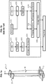
figure 1b , discutée plus haut, présente les différents procédés de mise en forme de l'alliage TiAI de l'art antérieur. - La
figure 2a , illustre la contrainte d'écoulement d'un lingot en alliage 48-2-2, en fonction de la déformation exercée, pour un ligot avant filage (trait en pointillé) et pour un lingot filé (trait plein). - La
figure 2b est une coupe d'un ligot en alliage 48-2-2 avant filage. - La
figure 2c est une coupe d'un ligot en alliage 48-2-2 après filage. - La
figure 3 illustre les différentes étapes du procédé selon l'invention, suivant plusieurs possibilités. - Les
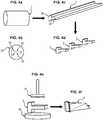
figures 4a à 4f illustrent le premier mode de réalisation du procédé selon l'invention et en particulier,- - la
figure 4a représente un lingot avant filage ; - - la
figure 4b représente la filière vue de face ; - - la
figure 4c représente un lingot après filage ; - - la
figure 4d représente un lingot découpé en tronçons ; - - la
figure 4e illustre schématiquement l'étape de forgeage ; - - la
figure 4f représente le tronçon de lingot après l'étape de forgeage.
- - la
- Les
figures 5a à 5e illustrent le second mode de réalisation du procédé selon l'invention. En particulier,- la
figure 5a représente un lingot avant filage ; - la
figure 5b représente la filière vue de face ; - la
figure 5c représente un lingot après filage ; - la
figure 5d représente un lingot découpé en tronçons ; - la
figure 5e illustre schématiquement l'étape de forgeage ; - la
figure 5f représente le tronçon de lingot après l'étape de forgeage.
- la
- Les
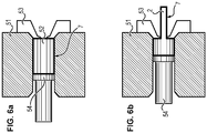
figures 6a et 6b illustrent l'étape de filage, lesfigures 6a et 6b illustrant un filage avec gaine. - Comme illustré sur la
figure 3 , le procédé de fabrication d'une aube de turbomachine, comporte des étapes de : - E1 formation d'un lingot 1 d'aluminiure de titane;
- E2 filage du lingot 1;
- E3 découpe transversale du lingot filé 2 de manière à obtenir des tronçons 3 de lingot filé ;
- E4 forgeage des tronçons 3 de lingot filé de manière à obtenir une aube de turbomachine 4.
- L'étape E1 consiste à former un lingot 1 en aluminiure de titane.
- Le procédé peut être appliqué à tout type d'aluminiures de titane.
- En particulier, le procédé peut être appliqué à l'alliage Ti-48Al-2Cr-2Nb (% atomiques)), par la suite noté TiAI 48-2-2. Il constitue un compromis acceptable en termes de propriétés mécaniques.
- En particulier, le procédé peut être appliqué à des alliages dit beta de type représenté par la formule Ti-Al(a)Nb(b)Mo(c)B(d) dans laquelle 'a', 'b', 'c' et 'd' sont exprimés en pourcentage atomique, 'a' variant entre environ 44 et environ 48, 'b' variant entre environ 2 et environ 6, 'c' variant entre environ 0 et environ 2 et 'd' variant entre environ 0,01 et environ 1,0. Ces alliages présentent une résistance et une dureté excellentes.
- Le procédé peut également être appliqué à des alliages de type représenté par la formule Ti-Al-Cr-Nb-Si-Fe-Mo-Zr , comme par exemple un alliage contenant en atomes 44 à 49 % d'aluminium, 0,5 à 3 % de zirconium, 0,5 à 2 % de fer, 0,5 à 2 % de molybdène, 0,2 à 0,5 % de silicium, 0 à 3 % de niobium, le complément à 100% du titane et des impuretés inévitables.
- Le lingot est typiquement élaboré par coulée de métal liquide (procédé couramment appelé VIM pour 'Vacuun Induction Melting'). Lors de la coulée de métal liquide les différents constituants destinés à former l'alliage sont fusionnés par chauffage, puis le bain de matière métallique en fusion est coulé dans une enceinte sous vide. Le lingot 1 est typiquement de forme cylindrique de section circulaire. A cet effet, l'enceinte est de forme cylindrique creuse.
- Dans le cas où le lingot est réalisé par coulée dans une enceinte sous vide, la structure obtenue est une structure de solidification relativement hétérogène et avec une taille de grain de coulée très importante (de l'ordre de 300-500 µm). Dans ce cas, le filage va homogénéiser et affiner la structure grossière de grain de départ, jusqu'à obtenir taille de grains faible de l'ordre de 50 µm.
- Les alliages de type beta ont tendance à ségréger chimiquement lors de leur élaboration. Le filage permet d'agir sur la taille des grains mais n'a pas d'impact sur l'homogénéité chimique de l'alliage. C'est pourquoi pour ces derniers, il peut être intéressant de partir de poudres afin de constituer un demi-produit, avant forgeage, plus homogène chimiquement. A cet effet, la coulée de métal liquide est suivie d'une atomisation de poudre. Ce procédé consiste à atomiser un filet de matière obtenu à partir du bain de matière métallique en fusion. Les gouttelettes de matière se solidifient dans une chambre d'atomisation grâce à un échange convectif avec le gaz ambiant, typiquement de l'argon, et donnent de la poudre. Celle-ci est collectée à la sortie des gaz d'atomisation et placée dans une gaine 7, qui peut être usinée dans un matériau différent de celui de la poudre comme par exemple l'inox. La gaine 7 est typiquement de forme cylindrique creuse. L'utilisation de la métallurgie des poudres permet de remédier aux difficultés d'homogénéisation des alliages ségrégeants. Toutes les opérations de manipulation de la poudre, de remplissage de la gaine ainsi que son sellage doivent être réalisées sous atmosphère neutre ou sous vide de manière à limiter la contamination de cette dernière par l'oxygène. L'utilisation combinée d'une poudre fine ainsi que du filage permet d'obtenir des barres ayant une microstructure homogène chimiquement et ayant une taille de grains faible. Une fois que le lingot est réalisé par atomisation de poudres, l'étape de filage permet de regrouper en une seule étape la compaction de la poudre, son frittage, sa mise en forme et surtout de conserver une microstructure fine, que l'on pourra faire grossir si besoin
- Lors de l'étape E2, le lingot subit une mise en forme par filage. Le filage permet la mise en forme du lingot par compression. Le lingot mis en forme par filage est appelé lingot filé 2. L'étape E2 consiste à faire passer le lingot (éventuellement rendu ductile par chauffage à la température dite de filage) par un orifice 52 d'une filière 53, comme illustré sur les
figures 6a, et 6b . Comme illustré sur lafigure 6a , le lingot 1, généralement placé dans un conteneur 51, est poussé dans la filière 53 au moyen d'une presse 54, typiquement une presse hydraulique, une pompe ou d'une vis d'extrudeuse, de manière à le faire ressortir par l'orifice 52 en exerçant une poussée. À partir d'un certain effort exercé par la presse 54, il y a écoulement plastique du lingot à travers l'orifice 52 de la filière 53, comme illustré sur lafigure 6b . Le lingot filé 2 est donc de forme avec une section transversale correspondant à la forme de l'orifice 52. - Le filage permet d'homogénéiser et d'affiner très fortement la structure de l'alliage et par conséquent de réduire la contrainte d'écoulement, à savoir la contrainte nécessaire pour provoquer une déformation plastique de l'alliage.
- Comme on peut le voir sur la
figure 2b , qui est une coupe d'un lingot en alliage 48-2-2 avant filage, et lafigure 2c , qui est une coupe d'un ligot en alliage 48-2-2 après filage, le filage permet d'affiner la structure de l'alliage, c'est-à-dire de réduire la taille de grains de l'alliage. Les résultats des inventeurs, illustrés sur lafigure 2a , montrent que l'étape de filage permet de réduire de 30 à 40% la contrainte d'écoulement de l'alliage 48-2-2. Les inventeurs ont obtenus des résultats similaires avec d'autres alliages TiAI et notamment avec un alliage Ti-45Al-2.4Si. - Le filage permet, en même temps, de donner au lingot filé de forme dont la section est définie par la forme de l'orifice 52 de la filière 53. La forme de l'orifice 52 de la filière 53 est choisie de manière à ce que la forme du lingot filé s'approche de celle de la pièce finale, ce qui permet de réduire la déformation nécessaire lors de l'étape finale de forgeage conventionnel. Il est alors possible d'obtenir par forgeage conventionnel une pièce proche de la forme de la pièce finale, et ainsi de limiter l'étape d'usinage finale.
- A cet effet, le lingot 1 est filé dans une filière dont l'orifice 52 présente une fente principale 55 et au moins une fente latérale 56. La fente latérale 56 s'étend perpendiculairement à la fente principale 55, à partir de l'une des extrémités de celle-ci, et de part et d'autre de celle-ci, comme illustré sur les
figures 4b et5b . On obtient ainsi un lingot filé 2 ayant la forme d'une barre de section transversale présentant une branche principale 25 et au moins une branche latérale 26 perpendiculaire à la branche principale 25, comme illustré sur lesfigures 4c et5c . - Ici, la branche latérale est sensiblement perpendiculaire à la fente principale. Cependant il peut être considéré une branche latérale légèrement inclinée par rapport à la branche principale, cette inclinaison pouvant être de quelques degrés à une dizaine de degrés voire une trentaine de degrés.
- Dans un premier mode de réalisation illustré par les
figures 4a à 4f , l'orifice 52 de la filière 53 présente une fente principale 55 et une seule fente latérale 56 qui s'étend à partir de l'une des extrémités de la fente principale 55 perpendiculairement à celle-ci, comme illustré sur lafigure 4b . Autrement dit, l'orifice 52 de la filière 53 a une forme de T. Le lingot est filé de manière à obtenir un lingot filé 2 en forme de barre de section en forme de T, présentant une branche principale 25 et une branche latérale 26 perpendiculaire à la branche principale 25, comme illustré sur lafigure 4c . La pale 30 sera forgée dans la branche principale 25 tandis que le pied 10 de l'aube sera forgé dans la branche latérale 26. - Dans un second mode de réalisation illustré par les
figures 5a à 5f , l'orifice 52 de la filière 53 présente une fente principale 55, une première fente latérale 56 qui s'étend à partir de l'une extrémité de la fente principale 55 perpendiculairement à celle-ci, et une seconde fente latérale 57 qui s'étend à partir de l'autre extrémité de la fente principale 55 perpendiculairement à celle-ci, comme illustré sur lafigure 5b . Autrement dit, l'orifice 52 de la filière 53 a une section en forme de H. Le lingot est filé de manière à obtenir un lingot filé 2 en forme de barre ayant une section en forme de H, présentant une branche principale 25, une première branche latérale 26, s'étendant perpendiculairement à la branche principale 25 à partir d'une extrémité de celle-ci, et une seconde branche latérale 27 s'étendant perpendiculairement à la branche principale 25 à partir de l'autre extrémité de celle-ci, comme illustré sur lafigure 5c . Comme dans le premier mode de réalisation, la pale 30 sera forgée dans la branche principale 25 tandis que le pied 10 de l'aube sera forgé dans la première branche latérale 26. En outre, le talon 20 de l'aube sera forgé dans la seconde branche latérale 26. - Pour l'alliage TiAl 48-2-2, le filage est une étape relativement délicate. Des essais de filage sans gaine de lingots formés par coulée montrent souvent des criques profondes dans certaines zones de la barre. Dans ce cas, le lingot 1 est avantageusement enrobé d'une gaine 7, par exemple en inox, lors d'une étape de gainage E1', afin de réduire le refroidissement pariétal du lingot lors du filage et éviter ainsi une déformation à une température localement trop basse qui peut entrainer des criques. Le lingot 1 enrobé de sa gaine 7 est porté à la température de filage avant passage dans la filière 53 au travers d'un pot de filage 51. Après filage, il faut prévoir une étape de dégainage E6 du lingot filé 2 qui consiste à éliminer la gaine, par exemple par tournage, avant forgeage. Il peut également être avantageux d'éliminer le matériau de gainage par enlèvement chimique.
- Par contre, pour les alliages de type beta, moins chargés en Al mais plus chargés en Nb et Mo, leur conférant une meilleure forgeabilité que le 48-2-2, le filage peut être réalisé sans gaine (pas selon les revendications).
- En fonction des propriétés mécaniques recherchées pour la fonctionnalité de la pièce finale, un traitement thermique classique peut être nécessaire pour régénérer une microstructure contrôlée. En effet, les structures après forgeage seront fines voire très fines. Certaines propriétés telles que le fluage, ne seront pas optimales après forgeage.
- Lors de l'étape E3, le lingot est découpé en tronçon. A cet effet, le lingot est découpé selon des plans transversaux par des technique classique de découpe des métaux telles que la découpe au jet d'eau, la découpe laser, ou la découpe au fil.
- Comme expliqué plus haut, le filage permet, préalablement au forgeage, d'affiner la structure des alliages TiAl, afin de réduire la contrainte d'écoulement de l'alliage, à savoir la contrainte nécessaire pour provoquer une déformation plastique de l'alliage. Il est alors possible d'employer, après filage, des moyens de forgeage conventionnels permettant d'obtenir une pièce proche de la forme finale de l'aube, ce qui n'était pas possible dans l'art antérieur. Par forgeage conventionnel, on entend forgeage à l'air libre et à matrice chaude par opposition au forgeage isotherme.
- Le forgeage consiste à appliquer une force importante sur le lingot filé 2 afin de la contraindre à épouser la forme de la pièce final, à savoir l'aube de turbomachine.
- Le forgeage est effectué en appliquant une force importante sur le lingot filé 2 à l'aide d'un dispositif de frappe 41, tel qu'une matrice déplacée hydrauliquement à une vitesse contrôlée, et d'un support 42, tel qu'une enclume ou une matrice fixe, comme illustré sur les
figures 4e , et5e . - Le lingot filé 2 ayant une forme de section transversale présentant une branche principale 25 et au moins une branche latérale 26 perpendiculaire à la branche principale 25, la pale 30 de l'aube est forgée dans la branche principale 25, et le pied 10 de l'aube est formé par forgeage dans la branche latérale 26. Si la section transversale du lingot filé présente deux branches latérales 25 et 27, le pied 10 de l'aube sera formé par forgeage dans l'une des branches latérales 25, et le talon 20 dans l'autre branche latérale 26. Ainsi, la forme du lingot filé 2 s'approche de celle de la pièce finale 4, ce qui permet de réduire la déformation nécessaire lors de l'étape de forgeage.
- Les aubes 4 obtenues par forgeage sont plus résistantes aux contraintes mécaniques car la déformation des métaux engendre un grand nombre de phénomènes métallurgiques, tant au niveau microscopique que macroscopique.
- Notamment, le filage provoque de par la forme du lingot filé, une orientation des grains lamellaires de l'alliage, par l'action du travail de déformation, dans la direction perpendiculaire à l'axe de chargement de l'aube. L'orientation des grains lamellaires de l'alliage dans la direction perpendiculaire à l'axe de chargement de l'aube, permet d'augmenter la résistance de l'aube aux contraintes mécanique auxquelles elle sera soumise en fonctionnement.
- Le forgeage n'a pas besoin d'être isotherme (le forgeage isotherme nécessite que les outillages soient portés aux températures de chauffage du métal qui sera forgé à savoir plus de 1000°) et peut être effectué à l'air libre en matrices chaudes avec une température d'outillage typiquement comprise entre 600° et 950°C.
Claims (5)
- Procédé de fabrication d'une aube de turbomachine (4), en aluminiure de titane, comportant une étape de :- (E1) formation d'un lingot (1) en aluminiure de titane ;- (E2) filage du lingot (1) à travers un orifice (52) d'une filière (53), l'orifice (52) présentant une fente principale (55) et au moins une fente latérale (56) qui s'étend à partir de l'une des extrémités de la fente principale (55) sensiblement perpendiculairement à celle-ci, de manière à obtenir un lingot filé (2) ayant la forme d'une barre de section transversale présentant une branche principale (25) et au moins une branche latérale (26) sensiblement perpendiculaire à la branche principale (25) ;- (E3) découpe transversale du lingot filé (2) de manière à obtenir des tronçons (3) de lingot filé ;- (E4) forgeage de chaque tronçon (3) de lingot filé de manière à obtenir une aube de turbomachine (4),le procédé de fabrication étant caractérisé en ce que le forgeage est réalisé en matrices chaudes avec une température comprise entre 600° et 950°C,en ce que le lingot (1) est formé par atomisation de poudre,et en ce que le procédé de fabrication comporte en outre une étape de gainage (E1') du lingot (1) préalablement au filage (E2) et une étape de dégainage (E6) entre l'étape de filage (E2) et l'étape de forgeage (E4).
- Procédé de fabrication d'une aube de turbomachine (4), selon la revendication 1, dans lequel l'orifice (52) de la filière (53) présente une unique fente latérale (56) qui s'étend à partir de l'une des extrémités de la fente principale (55) perpendiculairement à celle-ci, de manière à obtenir un lingot filé (2) en forme de barre de section présentant une branche principale (25) et une unique branche latérale (26) qui s'étend à partir de l'une des extrémités de la branche principale (25) perpendiculairement à celle-ci.
- Procédé de fabrication d'une aube de turbomachine (4), selon la revendication 1, dans lequel l'orifice (52) de la filière (53) présente une première fente latérale (56) qui s'étend à partir de l'une extrémité de la fente principale (55) sensiblement perpendiculairement à celle-ci, et une seconde fente latérale (57) qui s'étend à partir de l'autre extrémité de la fente principale (55) sensiblement perpendiculairement à celle-ci, de manière à obtenir un lingot filé (2) en forme de barre ayant une section présentant une branche principale (25), une première branche latérale (26), s'étendant sensiblement perpendiculairement à la branche principale (25) à partir d'une extrémité de celle-ci, et une seconde branche latérale (27) s'étendant sensiblement perpendiculairement à la branche principale (25) à partir de l'autre extrémité de celle-ci.
- Procédé de fabrication d'une aube de turbomachine (4), selon l'une des revendications précédentes, le forgeage étant réalisé à l'air libre.
- Procédé de fabrication d'une aube de turbomachine (4), selon l'une des revendications précédentes, comportant en outre une étape d'usinage après l'étape de forgeage.
Applications Claiming Priority (2)
| Application Number | Priority Date | Filing Date | Title |
|---|---|---|---|
| FR1554696A FR3036640B1 (fr) | 2015-05-26 | 2015-05-26 | Procede de fabrication d'une aube de turbomachine en tial |
| PCT/FR2016/051244 WO2016189254A1 (fr) | 2015-05-26 | 2016-05-26 | Procédé de fabrication d'une aube de turbomachine en tial |
Publications (2)
| Publication Number | Publication Date |
|---|---|
| EP3302874A1 EP3302874A1 (fr) | 2018-04-11 |
| EP3302874B1 true EP3302874B1 (fr) | 2021-10-13 |
Family
ID=54356414
Family Applications (1)
| Application Number | Title | Priority Date | Filing Date |
|---|---|---|---|
| EP16733637.9A Active EP3302874B1 (fr) | 2015-05-26 | 2016-05-26 | Procédé de fabrication d'une aube de turbomachine en tial |
Country Status (9)
| Country | Link |
|---|---|
| US (1) | US10758957B2 (fr) |
| EP (1) | EP3302874B1 (fr) |
| JP (1) | JP6873922B2 (fr) |
| CN (1) | CN107666977B (fr) |
| BR (1) | BR112017025210A2 (fr) |
| CA (1) | CA2986788A1 (fr) |
| FR (1) | FR3036640B1 (fr) |
| RU (1) | RU2706933C2 (fr) |
| WO (1) | WO2016189254A1 (fr) |
Families Citing this family (8)
| Publication number | Priority date | Publication date | Assignee | Title |
|---|---|---|---|---|
| DE102017212082A1 (de) * | 2017-07-14 | 2019-01-17 | MTU Aero Engines AG | Schmieden bei hohen temperaturen, insbesondere von titanaluminiden |
| FR3074217B1 (fr) * | 2017-11-24 | 2020-09-25 | Safran Aircraft Engines | Aube pour une turbomachine d'aeronef |
| JP7124652B2 (ja) * | 2018-11-13 | 2022-08-24 | 株式会社豊田自動織機 | TiAl合金製翼車の製造方法 |
| FR3109107B1 (fr) * | 2020-04-09 | 2023-06-23 | Airbus Operations Sas | Procédé de fabrication d’un profilé par extrusion et forgeage, profilé ainsi obtenu |
| CN112122524A (zh) * | 2020-09-18 | 2020-12-25 | 中国航发沈阳黎明航空发动机有限责任公司 | 一种镍基高温合金航空发动机转子叶片热模锻工艺 |
| DE102021000614A1 (de) | 2021-02-08 | 2022-08-11 | Access E.V. | Kokille zur rissfreien Herstellung eines Metallgegenstandes mit mindestens einem Hinterschnitt, insbesondere aus intermetallischen Legierungen wie TiAl, FeAl und anderen spröden oder rissanfälligen Werkstoffen, sowie ein entsprechendes Verfahren. |
| BE1029728B1 (fr) | 2021-09-03 | 2023-04-11 | Safran Aero Boosters | Procédé de fabrication d’une aube de turbomachine |
| CN115446546B (zh) * | 2022-09-02 | 2024-07-19 | 中国航发北京航空材料研究院 | 一种高温合金整体叶盘增材制造过程变形控制装置及方法 |
Family Cites Families (24)
| Publication number | Priority date | Publication date | Assignee | Title |
|---|---|---|---|---|
| US5411700A (en) * | 1987-12-14 | 1995-05-02 | United Technologies Corporation | Fabrication of gamma titanium (tial) alloy articles by powder metallurgy |
| EP0513407B1 (fr) * | 1991-05-13 | 1995-07-19 | Asea Brown Boveri Ag | Procédé de fabrication d' une aube de turbine |
| JP2707520B2 (ja) * | 1992-03-06 | 1998-01-28 | 大同特殊鋼株式会社 | Ti−Al系耐熱部品 |
| FR2735406B1 (fr) | 1995-06-19 | 1997-07-11 | Commissariat Energie Atomique | Procede de mise en forme par frittage reactif de materiaux intermetalliques |
| JPH1110270A (ja) | 1997-06-18 | 1999-01-19 | Daido Steel Co Ltd | α+β型チタン合金の温間鍛造方法 |
| JP4287991B2 (ja) * | 2000-02-23 | 2009-07-01 | 三菱重工業株式会社 | TiAl基合金及びその製造方法並びにそれを用いた動翼 |
| ATE296703T1 (de) * | 2000-05-17 | 2005-06-15 | Saab Ab | Herstellung von teilen für ventilmechanismus von verbrennungsmotoren |
| DE10062310C2 (de) * | 2000-12-14 | 2002-11-07 | Geesthacht Gkss Forschung | Verfahren zur Behandlung metallischer Werkstoffe |
| FR2855439B1 (fr) | 2003-05-27 | 2006-07-14 | Snecma Moteurs | Procede de fabrication d'une aube creuse pour turbomachine. |
| RU2254200C1 (ru) * | 2003-12-22 | 2005-06-20 | Федеральное государственное унитарное предприятие "Московское машиностроительное производственное предприятие "САЛЮТ" (ФГУП "ММПП "САЛЮТ") | Способ изготовления заготовки лопатки |
| ES2305593T3 (es) | 2004-02-26 | 2008-11-01 | Gkss-Forschungszentrum Geesthacht Gmbh | Procedimiento para fabricar componentes y productos semielaborados que contienen aleaciones intermetalicas de aluminuro de titanio, asi como componentes que pueden fabricarse con este procedimiento. |
| FR2873940B1 (fr) * | 2004-08-03 | 2008-01-04 | Snecma Moteurs Sa | Procede de fabrication de pieces constitutives d'une aube creuse par laminage |
| JP2007056340A (ja) * | 2005-08-25 | 2007-03-08 | Mitsubishi Heavy Ind Ltd | 耐熱性TiAl基合金部材の製造方法及び耐熱性TiAl基合金部材 |
| US7923127B2 (en) | 2005-11-09 | 2011-04-12 | United Technologies Corporation | Direct rolling of cast gamma titanium aluminide alloys |
| CN101618499B (zh) * | 2008-07-04 | 2010-12-29 | 沈阳黎明航空发动机(集团)有限责任公司 | 一种消除辊轧叶片咬口粗晶的方法 |
| EP2998062A1 (fr) * | 2009-11-30 | 2016-03-23 | Snecma | Procédé de réalisation d'un renfort métallique d'aube de turbomachine |
| US8357328B2 (en) * | 2009-12-14 | 2013-01-22 | General Electric Company | Methods for processing nanostructured ferritic alloys, and articles produced thereby |
| US8876992B2 (en) * | 2010-08-30 | 2014-11-04 | United Technologies Corporation | Process and system for fabricating gamma TiAl turbine engine components |
| FR2997884B3 (fr) * | 2012-11-09 | 2015-06-26 | Mecachrome France | Procede et dispositif de fabrication d'aubes de turbines. |
| WO2015009454A1 (fr) * | 2013-07-15 | 2015-01-22 | United Technologies Corporation | Régulation d'espacement de turbine à l'aide d'un matériau à faible alpha |
| RU2551333C1 (ru) * | 2013-11-20 | 2015-05-20 | Федеральное государственное бюджетное образовательное учреждение высшего профессионального образования "Уфимский государственный авиационный технический университет" | Способ изготовления лопаток газотурбинного двигателя |
| CN103801581B (zh) * | 2014-01-24 | 2015-11-11 | 北京科技大学 | 一种高铌钛铝基合金板材的制备方法 |
| CN103789572A (zh) * | 2014-02-28 | 2014-05-14 | 洛阳双瑞精铸钛业有限公司 | 一种高铝钛合金球头用板的生产工艺 |
| CN104328501B (zh) * | 2014-10-09 | 2017-06-27 | 南京理工大学 | 一种片层取向完全可控的TiAl单晶合金及其制备方法 |
-
2015
- 2015-05-26 FR FR1554696A patent/FR3036640B1/fr not_active Expired - Fee Related
-
2016
- 2016-05-26 WO PCT/FR2016/051244 patent/WO2016189254A1/fr not_active Ceased
- 2016-05-26 EP EP16733637.9A patent/EP3302874B1/fr active Active
- 2016-05-26 RU RU2017145407A patent/RU2706933C2/ru active
- 2016-05-26 BR BR112017025210-4A patent/BR112017025210A2/pt active Search and Examination
- 2016-05-26 CN CN201680030781.6A patent/CN107666977B/zh not_active Expired - Fee Related
- 2016-05-26 CA CA2986788A patent/CA2986788A1/fr not_active Abandoned
- 2016-05-26 US US15/576,783 patent/US10758957B2/en not_active Expired - Fee Related
- 2016-05-26 JP JP2017561262A patent/JP6873922B2/ja not_active Expired - Fee Related
Non-Patent Citations (1)
| Title |
|---|
| None * |
Also Published As
| Publication number | Publication date |
|---|---|
| CN107666977B (zh) | 2020-05-22 |
| JP2018528864A (ja) | 2018-10-04 |
| CN107666977A (zh) | 2018-02-06 |
| WO2016189254A1 (fr) | 2016-12-01 |
| FR3036640B1 (fr) | 2017-05-12 |
| US10758957B2 (en) | 2020-09-01 |
| RU2017145407A3 (fr) | 2019-10-22 |
| US20180304329A1 (en) | 2018-10-25 |
| BR112017025210A2 (pt) | 2018-08-07 |
| EP3302874A1 (fr) | 2018-04-11 |
| CA2986788A1 (fr) | 2016-12-01 |
| JP6873922B2 (ja) | 2021-05-19 |
| RU2706933C2 (ru) | 2019-11-21 |
| RU2017145407A (ru) | 2019-06-27 |
| FR3036640A1 (fr) | 2016-12-02 |
Similar Documents
| Publication | Publication Date | Title |
|---|---|---|
| WO2016189254A1 (fr) | Procédé de fabrication d'une aube de turbomachine en tial | |
| CA2802943C (fr) | Procede de realisation d'un renfort metallique d'aube de turbomachine | |
| CA2804957C (fr) | Procede de realisation d'une piece massive | |
| EP3007844B1 (fr) | Procédé de fabrication d'une pièce en alliage en titane-aluminium | |
| JP4368455B2 (ja) | 内燃機関用ポペット弁の製造方法 | |
| EP2507010B1 (fr) | Procédé de réalisation d'un renfort métallique d'aube de turbomachine | |
| US20190299288A1 (en) | METHOD FOR PRODUCING A COMPONENT FROM A GRADED TiAl ALLOY AND COMPONENT PRODUCED THEREFROM | |
| EP3129516B1 (fr) | Traitement thermique d'un alliage à base d'aluminure de titane | |
| EP2321440A2 (fr) | Procédé de préparation d'une pièce en superalliage base nickel et pièce ainsi obtenue | |
| WO1998002387A1 (fr) | Fond de filiere a tetons rapportes | |
| EP3223981B1 (fr) | Procédé de fabrication de pièces tridimensionnelles en alliage d'aluminium et de titane | |
| CA2887335C (fr) | Procede de fabrication d'au moins une piece metallique de turbomachine | |
| FR2883785A1 (fr) | Procede de production d'un metal d'apport consommable servant a une operation de soudage | |
| EP2506997A1 (fr) | Moule avec noyau intérieur stabilisé, procédé de coulée et pièce coulée | |
| EP4076794B1 (fr) | Procédé de fabrication d'une roue aubagée de turbomachine composite à renfort céramique | |
| EP3188857B1 (fr) | Procede de production d'un noyau ceramique | |
| EP3310527B1 (fr) | Electrode de soudage et procede de fabrication d'une electrode de soudage | |
| WO2023227929A1 (fr) | Alliage pour la fabrication d'outillages destinés à la fabrication de pièces aéronautiques réalisées en matériau composite | |
| FR3132913A1 (fr) | Poudre d’alliage, procédé de fabrication d’une pièce à base de cet alliage et pièce ainsi obtenue. | |
| FR3113254A1 (fr) | Protection contre l’oxydation ou la corrosion d’une pièce creuse en superalliage | |
| BE558549A (fr) | ||
| FR2962482A1 (fr) | Procede de realisation d’une piece massive |
Legal Events
| Date | Code | Title | Description |
|---|---|---|---|
| STAA | Information on the status of an ep patent application or granted ep patent |
Free format text: STATUS: THE INTERNATIONAL PUBLICATION HAS BEEN MADE |
|
| PUAI | Public reference made under article 153(3) epc to a published international application that has entered the european phase |
Free format text: ORIGINAL CODE: 0009012 |
|
| STAA | Information on the status of an ep patent application or granted ep patent |
Free format text: STATUS: REQUEST FOR EXAMINATION WAS MADE |
|
| 17P | Request for examination filed |
Effective date: 20171222 |
|
| AK | Designated contracting states |
Kind code of ref document: A1 Designated state(s): AL AT BE BG CH CY CZ DE DK EE ES FI FR GB GR HR HU IE IS IT LI LT LU LV MC MK MT NL NO PL PT RO RS SE SI SK SM TR |
|
| AX | Request for extension of the european patent |
Extension state: BA ME |
|
| DAV | Request for validation of the european patent (deleted) | ||
| DAX | Request for extension of the european patent (deleted) | ||
| STAA | Information on the status of an ep patent application or granted ep patent |
Free format text: STATUS: EXAMINATION IS IN PROGRESS |
|
| 17Q | First examination report despatched |
Effective date: 20200616 |
|
| REG | Reference to a national code |
Ref country code: DE Ref legal event code: R079 Ref document number: 602016064874 Country of ref document: DE Free format text: PREVIOUS MAIN CLASS: B23P0013020000 Ipc: B23P0013040000 |
|
| GRAP | Despatch of communication of intention to grant a patent |
Free format text: ORIGINAL CODE: EPIDOSNIGR1 |
|
| STAA | Information on the status of an ep patent application or granted ep patent |
Free format text: STATUS: GRANT OF PATENT IS INTENDED |
|
| RIC1 | Information provided on ipc code assigned before grant |
Ipc: B22F 5/04 20060101ALN20210512BHEP Ipc: B21K 3/04 20060101ALN20210512BHEP Ipc: B21C 35/02 20060101ALN20210512BHEP Ipc: B21C 23/16 20060101ALN20210512BHEP Ipc: B21C 23/14 20060101ALN20210512BHEP Ipc: B21C 23/00 20060101ALN20210512BHEP Ipc: B22F 3/20 20060101ALN20210512BHEP Ipc: B22F 3/17 20060101ALN20210512BHEP Ipc: B23P 15/02 20060101ALI20210512BHEP Ipc: B23P 13/04 20060101AFI20210512BHEP |
|
| INTG | Intention to grant announced |
Effective date: 20210602 |
|
| GRAS | Grant fee paid |
Free format text: ORIGINAL CODE: EPIDOSNIGR3 |
|
| GRAA | (expected) grant |
Free format text: ORIGINAL CODE: 0009210 |
|
| STAA | Information on the status of an ep patent application or granted ep patent |
Free format text: STATUS: THE PATENT HAS BEEN GRANTED |
|
| AK | Designated contracting states |
Kind code of ref document: B1 Designated state(s): AL AT BE BG CH CY CZ DE DK EE ES FI FR GB GR HR HU IE IS IT LI LT LU LV MC MK MT NL NO PL PT RO RS SE SI SK SM TR |
|
| REG | Reference to a national code |
Ref country code: GB Ref legal event code: FG4D Free format text: NOT ENGLISH |
|
| REG | Reference to a national code |
Ref country code: CH Ref legal event code: EP |
|
| REG | Reference to a national code |
Ref country code: DE Ref legal event code: R096 Ref document number: 602016064874 Country of ref document: DE |
|
| REG | Reference to a national code |
Ref country code: IE Ref legal event code: FG4D Free format text: LANGUAGE OF EP DOCUMENT: FRENCH |
|
| REG | Reference to a national code |
Ref country code: AT Ref legal event code: REF Ref document number: 1437835 Country of ref document: AT Kind code of ref document: T Effective date: 20211115 |
|
| REG | Reference to a national code |
Ref country code: SE Ref legal event code: TRGR |
|
| REG | Reference to a national code |
Ref country code: LT Ref legal event code: MG9D |
|
| REG | Reference to a national code |
Ref country code: NL Ref legal event code: MP Effective date: 20211013 |
|
| REG | Reference to a national code |
Ref country code: AT Ref legal event code: MK05 Ref document number: 1437835 Country of ref document: AT Kind code of ref document: T Effective date: 20211013 |
|
| PG25 | Lapsed in a contracting state [announced via postgrant information from national office to epo] |
Ref country code: RS Free format text: LAPSE BECAUSE OF FAILURE TO SUBMIT A TRANSLATION OF THE DESCRIPTION OR TO PAY THE FEE WITHIN THE PRESCRIBED TIME-LIMIT Effective date: 20211013 Ref country code: LT Free format text: LAPSE BECAUSE OF FAILURE TO SUBMIT A TRANSLATION OF THE DESCRIPTION OR TO PAY THE FEE WITHIN THE PRESCRIBED TIME-LIMIT Effective date: 20211013 Ref country code: FI Free format text: LAPSE BECAUSE OF FAILURE TO SUBMIT A TRANSLATION OF THE DESCRIPTION OR TO PAY THE FEE WITHIN THE PRESCRIBED TIME-LIMIT Effective date: 20211013 Ref country code: BG Free format text: LAPSE BECAUSE OF FAILURE TO SUBMIT A TRANSLATION OF THE DESCRIPTION OR TO PAY THE FEE WITHIN THE PRESCRIBED TIME-LIMIT Effective date: 20220113 Ref country code: AT Free format text: LAPSE BECAUSE OF FAILURE TO SUBMIT A TRANSLATION OF THE DESCRIPTION OR TO PAY THE FEE WITHIN THE PRESCRIBED TIME-LIMIT Effective date: 20211013 |
|
| PG25 | Lapsed in a contracting state [announced via postgrant information from national office to epo] |
Ref country code: IS Free format text: LAPSE BECAUSE OF FAILURE TO SUBMIT A TRANSLATION OF THE DESCRIPTION OR TO PAY THE FEE WITHIN THE PRESCRIBED TIME-LIMIT Effective date: 20220213 Ref country code: PT Free format text: LAPSE BECAUSE OF FAILURE TO SUBMIT A TRANSLATION OF THE DESCRIPTION OR TO PAY THE FEE WITHIN THE PRESCRIBED TIME-LIMIT Effective date: 20220214 Ref country code: PL Free format text: LAPSE BECAUSE OF FAILURE TO SUBMIT A TRANSLATION OF THE DESCRIPTION OR TO PAY THE FEE WITHIN THE PRESCRIBED TIME-LIMIT Effective date: 20211013 Ref country code: NO Free format text: LAPSE BECAUSE OF FAILURE TO SUBMIT A TRANSLATION OF THE DESCRIPTION OR TO PAY THE FEE WITHIN THE PRESCRIBED TIME-LIMIT Effective date: 20220113 Ref country code: NL Free format text: LAPSE BECAUSE OF FAILURE TO SUBMIT A TRANSLATION OF THE DESCRIPTION OR TO PAY THE FEE WITHIN THE PRESCRIBED TIME-LIMIT Effective date: 20211013 Ref country code: LV Free format text: LAPSE BECAUSE OF FAILURE TO SUBMIT A TRANSLATION OF THE DESCRIPTION OR TO PAY THE FEE WITHIN THE PRESCRIBED TIME-LIMIT Effective date: 20211013 Ref country code: HR Free format text: LAPSE BECAUSE OF FAILURE TO SUBMIT A TRANSLATION OF THE DESCRIPTION OR TO PAY THE FEE WITHIN THE PRESCRIBED TIME-LIMIT Effective date: 20211013 Ref country code: GR Free format text: LAPSE BECAUSE OF FAILURE TO SUBMIT A TRANSLATION OF THE DESCRIPTION OR TO PAY THE FEE WITHIN THE PRESCRIBED TIME-LIMIT Effective date: 20220114 Ref country code: ES Free format text: LAPSE BECAUSE OF FAILURE TO SUBMIT A TRANSLATION OF THE DESCRIPTION OR TO PAY THE FEE WITHIN THE PRESCRIBED TIME-LIMIT Effective date: 20211013 |
|
| REG | Reference to a national code |
Ref country code: DE Ref legal event code: R097 Ref document number: 602016064874 Country of ref document: DE |
|
| PG25 | Lapsed in a contracting state [announced via postgrant information from national office to epo] |
Ref country code: SM Free format text: LAPSE BECAUSE OF FAILURE TO SUBMIT A TRANSLATION OF THE DESCRIPTION OR TO PAY THE FEE WITHIN THE PRESCRIBED TIME-LIMIT Effective date: 20211013 Ref country code: SK Free format text: LAPSE BECAUSE OF FAILURE TO SUBMIT A TRANSLATION OF THE DESCRIPTION OR TO PAY THE FEE WITHIN THE PRESCRIBED TIME-LIMIT Effective date: 20211013 Ref country code: RO Free format text: LAPSE BECAUSE OF FAILURE TO SUBMIT A TRANSLATION OF THE DESCRIPTION OR TO PAY THE FEE WITHIN THE PRESCRIBED TIME-LIMIT Effective date: 20211013 Ref country code: EE Free format text: LAPSE BECAUSE OF FAILURE TO SUBMIT A TRANSLATION OF THE DESCRIPTION OR TO PAY THE FEE WITHIN THE PRESCRIBED TIME-LIMIT Effective date: 20211013 Ref country code: DK Free format text: LAPSE BECAUSE OF FAILURE TO SUBMIT A TRANSLATION OF THE DESCRIPTION OR TO PAY THE FEE WITHIN THE PRESCRIBED TIME-LIMIT Effective date: 20211013 Ref country code: CZ Free format text: LAPSE BECAUSE OF FAILURE TO SUBMIT A TRANSLATION OF THE DESCRIPTION OR TO PAY THE FEE WITHIN THE PRESCRIBED TIME-LIMIT Effective date: 20211013 |
|
| PLBE | No opposition filed within time limit |
Free format text: ORIGINAL CODE: 0009261 |
|
| STAA | Information on the status of an ep patent application or granted ep patent |
Free format text: STATUS: NO OPPOSITION FILED WITHIN TIME LIMIT |
|
| 26N | No opposition filed |
Effective date: 20220714 |
|
| PG25 | Lapsed in a contracting state [announced via postgrant information from national office to epo] |
Ref country code: AL Free format text: LAPSE BECAUSE OF FAILURE TO SUBMIT A TRANSLATION OF THE DESCRIPTION OR TO PAY THE FEE WITHIN THE PRESCRIBED TIME-LIMIT Effective date: 20211013 |
|
| PG25 | Lapsed in a contracting state [announced via postgrant information from national office to epo] |
Ref country code: SI Free format text: LAPSE BECAUSE OF FAILURE TO SUBMIT A TRANSLATION OF THE DESCRIPTION OR TO PAY THE FEE WITHIN THE PRESCRIBED TIME-LIMIT Effective date: 20211013 |
|
| REG | Reference to a national code |
Ref country code: CH Ref legal event code: PL |
|
| REG | Reference to a national code |
Ref country code: SE Ref legal event code: EUG |
|
| REG | Reference to a national code |
Ref country code: BE Ref legal event code: MM Effective date: 20220531 |
|
| GBPC | Gb: european patent ceased through non-payment of renewal fee |
Effective date: 20220526 |
|
| PG25 | Lapsed in a contracting state [announced via postgrant information from national office to epo] |
Ref country code: SE Free format text: LAPSE BECAUSE OF NON-PAYMENT OF DUE FEES Effective date: 20220527 Ref country code: MC Free format text: LAPSE BECAUSE OF FAILURE TO SUBMIT A TRANSLATION OF THE DESCRIPTION OR TO PAY THE FEE WITHIN THE PRESCRIBED TIME-LIMIT Effective date: 20211013 Ref country code: LU Free format text: LAPSE BECAUSE OF NON-PAYMENT OF DUE FEES Effective date: 20220526 Ref country code: LI Free format text: LAPSE BECAUSE OF NON-PAYMENT OF DUE FEES Effective date: 20220531 Ref country code: CH Free format text: LAPSE BECAUSE OF NON-PAYMENT OF DUE FEES Effective date: 20220531 |
|
| PG25 | Lapsed in a contracting state [announced via postgrant information from national office to epo] |
Ref country code: IE Free format text: LAPSE BECAUSE OF NON-PAYMENT OF DUE FEES Effective date: 20220526 |
|
| PG25 | Lapsed in a contracting state [announced via postgrant information from national office to epo] |
Ref country code: GB Free format text: LAPSE BECAUSE OF NON-PAYMENT OF DUE FEES Effective date: 20220526 Ref country code: BE Free format text: LAPSE BECAUSE OF NON-PAYMENT OF DUE FEES Effective date: 20220531 |
|
| PG25 | Lapsed in a contracting state [announced via postgrant information from national office to epo] |
Ref country code: IT Free format text: LAPSE BECAUSE OF NON-PAYMENT OF DUE FEES Effective date: 20220526 |
|
| PGFP | Annual fee paid to national office [announced via postgrant information from national office to epo] |
Ref country code: DE Payment date: 20230419 Year of fee payment: 8 |
|
| PG25 | Lapsed in a contracting state [announced via postgrant information from national office to epo] |
Ref country code: HU Free format text: LAPSE BECAUSE OF FAILURE TO SUBMIT A TRANSLATION OF THE DESCRIPTION OR TO PAY THE FEE WITHIN THE PRESCRIBED TIME-LIMIT; INVALID AB INITIO Effective date: 20160526 |
|
| PG25 | Lapsed in a contracting state [announced via postgrant information from national office to epo] |
Ref country code: MK Free format text: LAPSE BECAUSE OF FAILURE TO SUBMIT A TRANSLATION OF THE DESCRIPTION OR TO PAY THE FEE WITHIN THE PRESCRIBED TIME-LIMIT Effective date: 20211013 Ref country code: CY Free format text: LAPSE BECAUSE OF FAILURE TO SUBMIT A TRANSLATION OF THE DESCRIPTION OR TO PAY THE FEE WITHIN THE PRESCRIBED TIME-LIMIT Effective date: 20211013 |
|
| PG25 | Lapsed in a contracting state [announced via postgrant information from national office to epo] |
Ref country code: TR Free format text: LAPSE BECAUSE OF FAILURE TO SUBMIT A TRANSLATION OF THE DESCRIPTION OR TO PAY THE FEE WITHIN THE PRESCRIBED TIME-LIMIT Effective date: 20211013 |
|
| PG25 | Lapsed in a contracting state [announced via postgrant information from national office to epo] |
Ref country code: MT Free format text: LAPSE BECAUSE OF FAILURE TO SUBMIT A TRANSLATION OF THE DESCRIPTION OR TO PAY THE FEE WITHIN THE PRESCRIBED TIME-LIMIT Effective date: 20211013 |
|
| REG | Reference to a national code |
Ref country code: DE Ref legal event code: R119 Ref document number: 602016064874 Country of ref document: DE |
|
| PG25 | Lapsed in a contracting state [announced via postgrant information from national office to epo] |
Ref country code: DE Free format text: LAPSE BECAUSE OF NON-PAYMENT OF DUE FEES Effective date: 20241203 |
|
| PGFP | Annual fee paid to national office [announced via postgrant information from national office to epo] |
Ref country code: FR Payment date: 20250526 Year of fee payment: 10 |