EP3302845B1 - Behälter und selektiv geformte hülle sowie werkzeug und verfahren zur bereitstellung davon - Google Patents
Behälter und selektiv geformte hülle sowie werkzeug und verfahren zur bereitstellung davon Download PDFInfo
- Publication number
- EP3302845B1 EP3302845B1 EP16800444.8A EP16800444A EP3302845B1 EP 3302845 B1 EP3302845 B1 EP 3302845B1 EP 16800444 A EP16800444 A EP 16800444A EP 3302845 B1 EP3302845 B1 EP 3302845B1
- Authority
- EP
- European Patent Office
- Prior art keywords
- pressure
- assembly
- tooling
- bias
- tool assembly
- Prior art date
- Legal status (The legal status is an assumption and is not a legal conclusion. Google has not performed a legal analysis and makes no representation as to the accuracy of the status listed.)
- Active
Links
Images


Classifications
-
- B—PERFORMING OPERATIONS; TRANSPORTING
- B21—MECHANICAL METAL-WORKING WITHOUT ESSENTIALLY REMOVING MATERIAL; PUNCHING METAL
- B21D—WORKING OR PROCESSING OF SHEET METAL OR METAL TUBES, RODS OR PROFILES WITHOUT ESSENTIALLY REMOVING MATERIAL; PUNCHING METAL
- B21D22/00—Shaping without cutting, by stamping, spinning, or deep-drawing
- B21D22/20—Deep-drawing
- B21D22/24—Deep-drawing involving two drawing operations having effects in opposite directions with respect to the blank
-
- B—PERFORMING OPERATIONS; TRANSPORTING
- B21—MECHANICAL METAL-WORKING WITHOUT ESSENTIALLY REMOVING MATERIAL; PUNCHING METAL
- B21D—WORKING OR PROCESSING OF SHEET METAL OR METAL TUBES, RODS OR PROFILES WITHOUT ESSENTIALLY REMOVING MATERIAL; PUNCHING METAL
- B21D51/00—Making hollow objects
- B21D51/16—Making hollow objects characterised by the use of the objects
- B21D51/38—Making inlet or outlet arrangements of cans, tins, baths, bottles, or other vessels; Making can ends; Making closures
- B21D51/44—Making closures, e.g. caps
Definitions
- the disclosed concept relates generally to tooling for forming containers and, more particularly, to tooling for forming can ends or shells for metal containers such as, for example, beer or beverage cans, as well as food cans.
- the disclosed concept also relates to tooling for selectively forming a can end or shell to reduce the amount of material used therein.
- Metallic containers for holding products such as, for example, food and beverages, are typically provided with an easy open can end on which a pull tab is attached (e.g., without limitation, riveted) to a tear strip or severable panel.
- the severable panel is defined by a scoreline in the exterior surface (e.g., public side) of the can end.
- the pull tab is structured to be lifted and/or pulled to sever the scoreline and deflect and/or remove the severable panel, thereby creating an opening for dispensing the contents of the can.
- the can end When the can end is made, it originates as a can end shell, which is formed from a blank cut (e.g., blanked) from a sheet metal product (e.g., without limitation, sheet aluminum; sheet steel).
- the shell is then conveyed to a conversion press, which has a number of successive tool stations. As the shell advances from one tool station to the next, conversion operations such as, for example and without limitation, rivet forming, paneling, scoring, embossing, tab securing and tab staking, are performed until the shell is fully converted into the desired can end and is discharged from the press.
- the shell may be formed from a blank of material, wherein the blank of material has a base gauge prior to being formed, and wherein, after being formed, the material of the shell at or about the thinned portion has a thickness.
- the thickness of the material at or about the thinned portion is less than the base gauge.
- the thinned portion may include the chuck wall.
- tooling for forming a shell.
- the tooling comprises: an upper tool assembly; and a lower tool assembly cooperating with the upper tool assembly to form material disposed therebetween to include a center panel, a circumferential chuck wall, an annular countersink between the center panel and the circumferential chuck wall, and a curl extending radially outwardly from the chuck wall.
- the upper tool assembly and the lower tool assembly cooperate to selectively stretch the material of at least one predetermined portion of the shell relative to at least one other portion of the shell, thereby providing a corresponding thinned portion.
- Selectively thinning a predetermined portion of the shell relative to at least one other portion of the shell to provide a corresponding thinned portion of the shell has been determined to create certain complications such as an overloading condition on the tooling and/or press. Further, the selective thinning may result in excessively uneven thinning. That is, while some unevenness in the thinning is acceptable, excessive uneven thinning is not desirable. It is desirable that the selective thinning be accomplished with existing presses. There is, therefore, room for improvement in the tooling.
- two or more parts or components are “coupled” shall mean that the parts are joined or operate together either directly or indirectly, i.e., through one or more intermediate parts or components, so long as a link occurs.
- directly coupled means that two elements are directly in contact with each other. It is noted that moving parts, such as but not limited to circuit breaker contacts, are “directly coupled” when in one position, e.g., the closed, second position, but are not “directly coupled” when in the open, first position.
- fixedly coupled or “fixed” means that two components are coupled so as to move as one while maintaining a constant orientation relative to each other. Accordingly, when two elements are coupled, all portions of those elements are coupled.
- a description, however, of a specific portion of a first element being coupled to a second element, e.g., an axle first end being coupled to a first wheel, means that the specific portion of the first element is disposed closer to the second element than the other portions thereof.
- the phrase "removably coupled” means that one component is coupled with another component in an essentially temporary manner. That is, the two components are coupled in such a way that the joining or separation of the components is easy and would not damage the components.
- two components secured to each other with a limited number of readily accessible fasteners are "removably coupled” whereas two components that are welded together or joined by difficult to access fasteners are not “removably coupled.”
- a "difficult to access fastener” is one that requires the removal of one or more other components prior to accessing the fastener wherein the "other component” is not an access device such as, but not limited to, a door.
- operatively coupled means that a number of elements or assemblies, each of which is movable between a first position and a second position, or a first configuration and a second configuration, are coupled so that as the first element moves from one position/configuration to the other, the second element moves between positions/configurations as well. It is noted that a first element may be "operatively coupled" to another without the opposite being true.
- a "coupling assembly” includes two or more couplings or coupling components.
- the components of a coupling or coupling assembly are generally not part of the same element or other component. As such, the components of a “coupling assembly” may not be described at the same time in the following description.
- a "coupling” or “coupling component(s)” is one or more component(s) of a coupling assembly. That is, a coupling assembly includes at least two components that are structured to be coupled together. It is understood that the components of a coupling assembly are compatible with each other. For example, in a coupling assembly, if one coupling component is a snap socket, the other coupling component is a snap plug, or, if one coupling component is a bolt, then the other coupling component is a nut.
- “correspond” indicates that two structural components are sized and shaped to be similar to each other and may be coupled with a minimum amount of friction.
- an opening which "corresponds" to a member is sized slightly larger than the member so that the member may pass through the opening with a minimum amount of friction.
- This definition is modified if the two components are to fit "snugly" together. In that situation, the difference between the size of the components is even smaller whereby the amount of friction increases.
- the element defining the opening and/or the component inserted into the opening are made from a deformable or compressible material, the opening may even be slightly smaller than the component being inserted into the opening.
- surfaces, shapes, and lines two, or more, "corresponding" surfaces, shapes, or lines have generally the same size, shape, and contours.
- operatively engage means “engage and move.” That is, "operatively engage” when used in relation to a first component that is structured to move a movable or rotatable second component means that the first component applies a force sufficient to cause the second component to move.
- a screwdriver may be placed into contact with a screw. When no force is applied to the screwdriver, the screwdriver is merely “coupled” to the screw. If an axial force is applied to the screwdriver, the screwdriver is pressed against the screw and “engages” the screw. However, when a rotational force is applied to the screwdriver, the screwdriver "operatively engages" the screw and causes the screw to rotate.
- unitary means a component that is created as a single piece or unit. That is, a component that includes pieces that are created separately and then coupled together as a unit is not a “unitary” component or body.
- structured to [verb] means that the identified element or assembly has a structure that is shaped, sized, disposed, coupled and/or configured to perform the identified verb.
- a member that is "structured to move” is movably coupled to another element and includes elements that cause the member to move or the member is otherwise configured to move in response to other elements or assemblies.
- structured to [verb] recites structure and not function.
- structured to [verb] means that the identified element or assembly is intended to, and is designed to, perform the identified verb.
- an element that is merely capable of performing the identified verb but which is not intended to, and is not designed to, perform the identified verb is not "structured to [verb].”
- “associated” means that the elements are part of the same assembly and/or operate together, or, act upon/with each other in some manner.
- an automobile has four tires and four hub caps. While all the elements are coupled as part of the automobile, it is understood that each hubcap is “associated” with a specific tire.
- can and “container” are used substantially interchangeably to refer to any known or suitable container, which is structured to contain a substance (e.g., without limitation, liquid; food; any other suitable substance), and expressly includes, but is not limited to, beverage cans, such as beer and soda cans, as well as food cans.
- a substance e.g., without limitation, liquid; food; any other suitable substance
- beverage cans such as beer and soda cans, as well as food cans.
- can end shell is used substantially interchangeably with the term “can end.”
- the “can end shell” or simply the “shell” is the member that is acted upon and is converted by the disclosed tooling to provide the desired can end.
- tools As employed herein, the terms “tooling,” “tooling assembly” and “tool assembly” are used substantially interchangeably to refer to any known or suitable tool(s) or component(s) used to form (e.g., without limitation, stretch) shells in accordance with the disclosed concept.
- fastener refers to any suitable connecting or tightening mechanism expressly including, but not limited to, screws, bolts and the combinations of bolts and nuts (e.g., without limitation, lock nuts) and bolts, washers and nuts.
- number shall mean one or an integer greater than one (i.e., a plurality).
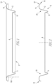
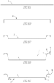
- Figures 1 and 2 show a can end shell 4 that is selectively formed. Specifically, as described in detail herein below, the material in certain predetermined areas of the shell 4, has been stretched, thereby thinning it, whereas other areas of the shell 4 preferably maintain the base metal thickness.
- a shell for a beverage can body 100 (partially shown in simplified form in phantom line drawing in Figure 1 )
- the disclosed concept could be employed to stretch and thin any known or suitable can end shell type and/or configuration for any known or suitable alternative type of container (e.g., without limitation, food can (not shown)), which is subsequently further formed (e.g., converted) into a finished can end for such a container.
- the shell 4 in the non-limiting example shown and described herein includes a circular center panel 6, which is connected by a substantially cylindrical panel wall 8 to an annular countersink 10.
- the example annular countersink 10 has a generally U-shaped cross-sectional profile.
- a tapered chuck wall 12 connects the countersink 10 to a crown 14, and a peripheral curl or outer lip 16 extends radially outwardly from the crown 14, as shown in Figures 1, 2 and 6E .
- the shell 4 has a base metal thickness of about 0.2083mm (.0082 inch). This base metal thickness is preferably substantially maintained in areas such as the center panel 6 and outer lip or curl 16. Keeping the center panel 6 in the base metal thickness helps with rivet, score and tab functions in the converted end (not explicitly shown). For example and without limitation, undesirable issues such as wrinkling and/or undesired scoreline and/or rivet or tab failures that can be attributed to reduced strength associated with thinned metal, are substantially eliminated by substantially maintaining the base thickness in the panel 6.
- substantially maintaining the outer lip 16 at base gauge helps with the seaming ability, for seaming the lid or can end 4 to the can body 100 (partially shown in simplified form in phantom line drawing in Figure 1 ). This area where preferably minimal to no thinning occurs, is indicated generally in Figure 2 by reference 18.
- the majority of the thinning preferably occurs in the chuck wall 12. More specifically, thinning preferably occurs in the area between the crown 14 and the countersink 10, which is generally indicated as area 20 in Figure 2 .
- the thickness of the material in the chuck wall 12 may be reduced to about 0.1880mm (.0074 inch). It will be appreciated that this is a substantial reduction, which results in significant weight reduction and cost savings over conventional can ends.
- the disclosed concept achieves material thinning and an associated reduction in the overall amount and weight of material, without incurring increased material processing charges associated with the stock material that is supplied to form the end product.
- increased processing e.g., rolling
- the base gauge i.e., thickness
- the disclosed concept achieves desired thinning and reduction, yet uses stock material having a more conventional and, therefore, less expensive base gauge.
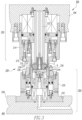
- Figures 3-5 show various tooling assemblies 200 (or "tooling 200") for stretching and thinning the shell material, in accordance with one non-limiting example embodiment of the disclosed concept.
- the selective forming e.g., stretching and thinning
- the process begins by introducing a blank of material (see, for example and without limitation, blank 2 of Figure 6A ) having a base metal thickness or gauge, between components of a tooling assembly 200.
- Figure 3 illustrates a single station 300, also known as a "pocket" 300, of a multiple station tooling assembly 200 coupled to a press 400.
- a single station 300 also known as a "pocket" 300
- typically one shell 4 is produced at each station 300 during each stroke of a conventional high-speed single-action or double-action mechanical press 400 to which the multiple station tooling assembly 200 of the disclosed concept is coupled.
- the tooling assembly 200 includes opposing upper and lower tool assemblies 202, 204 that cooperate to form (e.g., without limitation, stretch; thin; bend) metal (see, for example and without limitation, metal blank 2 of Figure 6A ) to achieve the desired shell (see, for example, and without limitation, shell 4 of Figures 1-3 , 5 and 6E ), in accordance with the disclosed concept.
- an annular blank and draw die 210 includes an upper flange portion 212, which is coupled to a retainer or riser body 214 by a number of fasteners 216.
- the blank and draw die 210 surrounds an upper pressure sleeve 218. That is, the blank and draw die 210 is proximate to the upper pressure sleeve 218 and is located radially outward from the upper pressure sleeve 218.
- An inner die member or die center 220 is supported within the upper pressure sleeve 218 by a die center riser 222.
- the blank and draw die 210 includes an inner curved forming surface 224 ( Figures 4 and 5 ).
- the lower end 227 of the upper pressure sleeve 218 includes a contoured annular forming surface 226 ( Figures 4 and 5 ).
- annular die retainer 230 is coupled to the lower die shoe 208 within a counterbore 232.
- An annular cut edge die 234 is coupled to the die retainer 230 by suitable fasteners 236.
- An annular lower pressure sleeve 240 includes a lower piston portion 242 for movement within the die retainer 230.
- the lower pressure sleeve 240 further includes an upper end 244 having a substantially flat surface which opposes the lower end of the aforementioned blank and draw die 210.
- the cut edge die 234 is located proximate to the lower pressure sleeve 240 and radially outward from the upper end 244 of the lower pressure sleeve 240, as shown.
- a die core ring 250 is disposed within the lower pressure sleeve 240, and includes an upper end 252 that opposes the lower end or forming surface 226 of the upper pressure sleeve 218, as best shown in Figures 4 and 5 .
- the upper end 252 includes a tapered surface 254, a rounded, or curvilinear, inner surface 256 and a rounded outer surface 258 (all shown in Figures 4 and 5 ).
- a circular panel punch 260 is disposed within the die core ring 250 opposite the aforementioned die center 220.
- the panel punch 260 includes a circular, substantially flat upper surface 262 having a peripheral rounded surface 264.
- a peripheral recessed portion 266 extends downwardly from the rounded surface 264, as best shown in Figures 4 and 5 .
- the foregoing tools of the upper tool assembly 202 and lower tool assembly 204 cooperate to form and, in particular, stretch and thin predetermined selected areas of, the shell 4, as will now be described in greater detail with respect to Figures 6A-6E , which illustrate the method and associated forming stages for forming the stretched and thinned shell 4.
- Figure 6A shows a first forming step wherein a blank 2 is provided using the aforementioned tooling assembly 200 ( Figures 3-5 ). More specifically, respective cut edges of the blank and draw die 210 and annular cut edge die 234 cooperate to cut (e.g., blank) the blank 2, for example, from a web or sheet of material.
- the tooling 200 cooperates to make a first bend, namely bending the peripheral edges of the blank 2 downward, as shown.
- the outer portions of the blank 2 are further formed, as shown.
- Figure 4 shows the tooling assembly 200 after a down stroke, wherein all of the tools shown have moved downward in the direction of arrows 410 to the positions shown. That is, the blank and draw die 210 and lower pressure sleeve 240 have moved downward in the direction of arrows 410 to further form the outer lip or curl 16.
- the upper pressure sleeve 218 has also moved downward in the direction of arrow 410, such that the forming surface 226 of the upper pressure sleeve 218 cooperates with the upper end 252 of the die core ring 250 to further form the crown 14, as shown.
- the die center 220 which also moves downward in the direction of arrow 410, stretches the metal of the blank 2 in the area of the chuck wall 12 as the substantially flat surface of the lower end of the die center 220 clamps the material between the die center 220 and the substantially flat upper surface 262 of the panel punch 260.
- the die center 220 and panel punch 260 both move downward in the direction of arrows 410 to stretch and thin the metal in the area of the chuck wall 12 as it cooperates with the tapered surface 254 of the die core ring 250.
- the material of the blank 2 is stretched and thinned in the area that will become the chuck wall 12, but little to no stretching or thinning occurs in the outer lip or curl area 16, or in the area that will be later formed into the panel 6 ( Figures 5 and 6E ) or in the lower area that will be later formed into the annular countersink 10 ( Figures 5 and 6E ). These areas remain substantially at base gauge metal thickness, as previously discussed hereinabove.
- FIG. 5 which illustrates the same tooling assembly 200 shown and described hereinabove with respect to the downward stroke of Figure 4
- some of the tooling assembly 200 has moved upward in Figure 5 in the direction of arrows 420 to form the panel 6 of the shell 4.
- the blank and draw die 210, die center 220, lower pressure sleeve 240, and panel punch 260 all move upward in the direction of arrow 420
- the upper pressure sleeve 218 has stopped moving downward in the direction of arrow 410 at this point and is holding pressure on the shell 4.
- the desired final form of the chuck wall 12 is provided by interaction of the upper pressure sleeve 218 and surfaces 254 and 256 of the die core ring 250.
- the panel 6 is formed by interaction of the substantially flat upper surface 262 of the panel punch 260 with the die center 220 as both of these components move upward in the direction of arrows 420 with the metal of the blank 2 that becomes the panel 6 disposed (e.g., clamped) therebetween.
- This movement also facilitates the formation of the cylindrical panel wall 8 and countersink 10. Specifically, as the panel punch 260 moves upward and the upper pressure sleeve 218 moves downward, the annular countersink 10 is formed within the peripheral recessed portion 266 of the panel punch 260.
- the cylindrical panel wall 8 is, therefore, formed as the metal cooperates with the peripheral rounded surface 264 of the panel punch 260.
- the disclosed concept provides tooling assembly 200 ( Figures 3-5 ) and methods for selectively stretching and thinning predetermined areas (see, for example and without limitation, area 20 of Figure 2 ) of a shell 4 ( Figures 1-3 , 5 and 6E ), thereby providing relatively substantially material and cost savings.
- the tooling 200A is substantially similar to the tooling assembly 200 discussed above and like elements will use like reference numbers.
- the die core ring upper end 252 opposes the lower end or forming surface 226 of the upper pressure sleeve 218.
- the outer portions of the blank 2 are formed by the forming surface 226 of the upper pressure sleeve 218 cooperating with the upper end 252 of the die core ring 250. That is, both the die core ring upper end 252 and the upper pressure sleeve forming surface 226 engage the blank 2.
- simultaneous engagement by elements disposed in opposition to each other is identified as "clamping.”
- the die core ring upper end 252 includes a tapered surface 254, a rounded inner surface 256 and a rounded outer surface 258.
- the die core ring upper end 252 further includes a generally horizontal surface 257.
- the "generally horizontal surface” 257 is that portion of the die core ring upper end that extends in a plane that is generally perpendicular to the axis of motion of the upper and lower tool assemblies 202, 204.
- "generally perpendicular” means perpendicular +/- about 10 degrees.
- the upper tool assembly 202 and the lower tool 204 assembly move between a separated, first position, wherein the upper tool assembly 202 is spaced from the lower tool assembly 204, and a forming position, wherein the upper tool assembly 202 is immediately adjacent the lower tool assembly 204 to selectively stretch the material of at least one predetermined portion of the shell 4 relative to at least one other portion of the shell, thereby providing a corresponding thinned portion.
- the upper pressure sleeve 218 and the die core ring 250 clamp the shell 4, as described above.
- the force acting on the blank 2 is, as used herein, the "clamping force.”
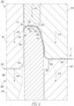
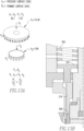
- the upper tool assembly 202 also includes a hybrid bias generating assembly 500 and the upper pressure sleeve forming surface 226 is a force concentrating forming surface 600.
- a “hybrid bias generating assembly” is an assembly that generates a bias in at least two different manners, and, the bias is applied to the same component. That is, as used herein, a “hybrid bias generating assembly” includes at least two bias generating assemblies that apply bias to the same component as well as a number of hybrid components.
- an assembly such as, but not limited to the hybrid bias generating assembly 500 described herein, which generates a bias via a compressed fluid (pressure bias) and via a spring (mechanical bias) satisfies the first requirement of being an active hybrid bias generating assembly.
- a device with a high pressure compressor and a low pressure compressor both producing pressure bias
- an assembly wherein one type of bias is applied to one component and another type of bias is applied to a different component is also not an “hybrid bias generating assembly” because the bias is not applied to the same component.
- the hybrid bias generating assembly 500 includes a pressure generating assembly 510, a mechanical bias assembly 550, and a number of hybrid components 570.
- hybrid components are components that are structured to be utilized by both bias generating assemblies, in the exemplary embodiment, the pressure generating assembly 510 and the mechanical bias assembly 550.
- the pressure generating assembly 510 includes a pressure generating device 512 (shown schematically), a pressure communication assembly 514 (shown schematically), a pressure chamber 516, and a piston assembly 518.
- the pressure generating device 512 is any known device structured to compress a fluid, or store compressed fluid, at an increased pressure, such as, but not limited to a fluid pump or compressor.
- the pressure communication assembly 514 includes any number of hoses, conduits, passages or any other construct capable of communicating a pressurized fluid. It is understood the pressure communication assembly 514 also includes seals, valves or any other construct required to control the communication of a pressurized fluid.
- the riser body 214 is sealingly coupled, directly coupled, or fixed to the upper die shoe 206.
- the riser body 214 defines the pressure chamber 516.
- the pressure chamber 516 includes a number of seals, not identified, required to prevent fluid from escaping.
- the piston assembly 518 includes a torus-shaped body 520 and, in an exemplary embodiment, a spring seat 554, as discussed below.
- the piston body and the spring seat are a unitary body. It is understood that the description of the piston body 520 applicable to the spring seat 554 is an embodiment that includes a spring seat 554.
- the piston body 520 corresponds to the pressure chamber 516 and the die center riser 222; it is understood that in an embodiment with a spring seat 554 the spring seat 554 corresponds to the pressure chamber 516 and the die center riser 222.
- the outer radial surface of the piston body 520, or the spring seat 554 is sealingly coupled to the inner surface of the pressure chamber 516, and, the inner radial surface of the piston body 520 is sealingly coupled to the outer surface of the die center riser 222.
- the piston assembly 518 includes a number of seals, not identified, required to prevent fluid from escaping the pressure chamber 516.
- the piston assembly 518 is movably disposed in the pressure chamber 516.
- the pressure generating device 512 is in fluid communication, via the pressure communication assembly 514, with the pressure chamber 516.
- the fluid, and therefore the pressure associated therewith, is communicated to the upper side of the piston body 520, hereinafter the "pressure surface” 521.
- the pressure surface 521 may be the upper surface of the spring seat 554.
- the total bias force is applied to the pressure surface 521 which has an area of between about 22.32cm 2 (3.46 in 2 ) to 111.61cm 2 (17.3 in 2 ), or about 66.97cm 2 (10.38 in 2 ).
- the pressure generating device 512 is structured to control the position of the piston assembly 518 in the pressure chamber 516, and is structured to move the piston assembly 518 in the pressure chamber 516.
- the piston assembly 518 is coupled to the upper pressure sleeve 218. That is, the upper pressure sleeve 218 includes an upper end 225 opposite the forming surface 226.
- the piston assembly 518 is coupled to the upper pressure sleeve upper end 225.
- the upper pressure sleeve 218 moves between an extended, first position, wherein the upper pressure sleeve lower end 227 is more spaced from the upper die shoe 206, and a retracted, second position, wherein the upper pressure sleeve lower end 227 is less spaced from the upper die shoe 206.
- the piston assembly 518 and the piston body 520 are “hybrid components” 570 as defined herein. That is, the piston assembly 518 and the piston body 520 are structured to be utilized by both the pressure generating assembly 510 and the mechanical bias assembly 550. It is noted that a piston associated exclusively with a pressure generating assembly 510 or exclusively with a mechanical bias assembly 550 cannot be a "hybrid component" as defined herein. That is, by definition, a piston assembly 518 associated exclusively with a pressure generating assembly 510 cannot be “structured to” be utilized by both bias generating assemblies. Similarly, by definition, a piston assembly 518 associated exclusively with a mechanical bias assembly 550 cannot be “structured to” be utilized by both bias generating assemblies. Accordingly, a piston associated exclusively with a pressure generating assembly 510 or exclusively with a mechanical bias assembly 550 is not a "hybrid component" as used herein.
- the mechanical bias assembly 550 includes a number of spring assemblies 552 and a number of spring seats 554.
- a spring assembly 552 includes a number of springs 560 associated with each spring seat 554.
- each spring assembly 552 includes a single, linear spring rate compression spring 560.
- the mechanical bias assembly 550 is structured to, and does, apply a bias at a generally linear rate during the compression of the spring assemblies 552.
- each spring assembly 552 includes a number of springs 560 that have a variable spring rate.
- the variable spring rate may be any of a progressive spring rate, a degressive spring rate, or a dual rate ( sometime identified as "progressive with knee") spring rate.
- a "progressive spring rate” is a spring rate that increases in compression in a non-linear manner.
- a “degressive spring rate” is a spring rate that decreases in compression in a non-linear manner.
- a “dual rate” spring rate is a spring rate that increases at a first linear, or generally linear, spring rate until a selected compression is achieved and thereafter the spring rate increases at a different second linear, or generally linear, spring rate. That is, the first and second spring rates are substantially different from each other.
- Variable rate springs include, but are not limited to, cylindrical springs with a variable pitch rate, conical springs, and mini block springs.
- all spring assemblies 552 include substantially the same type of spring 560. That is, for example, each spring assembly 552 includes a number of substantially similar linear spring rate compression springs 560, or, a number of substantially similar dual rate compression springs 560. In another exemplary embodiment, the spring assemblies 552 include different types of springs. For example, within the mechanical bias assembly 550, one set of spring assemblies 552 include a number of substantially similar linear spring rate compression springs 560, and, a second set includes a number of substantially similar dual rate compression springs 560.
- variable rate spring assemblies 552 may include any of a number of dual rate springs, a plurality of springs with different compression rates, a number of progressive springs, a number of degressive springs, or a combination of any of these .
- compression springs 560 are disposed in the pressure chamber 516.
- at least a lower spring seat 554' is a torus-shaped body 562 that corresponds to the pressure chamber 516 and the die center riser 222.
- the lower spring seat 554' is coupled, directly coupled, fixed, or unitary with, the upper side of the piston body 520.
- the compression springs 560 are sized to be in compression when disposed in the pressure chamber 516.
- the mechanical bias assembly 550 biases, i.e. operatively engages, the piston assembly 518 and therefore the upper pressure sleeve 218. That is, the upper pressure sleeve 218 is biased to its first position.
- the total bias pressure is a force of between about 31 kN (7,000 lbfs) and 40kN (9,000 lbfs), or about 35kN (8,000 lbfs) acting on the pressure surface 521, which has an area of between about 22.32cm 2 (3.46 in 2 ) to 111.61cm 2 (17.3 in 2 ), between about 44.65cm 2 (6.92 in 2 ) to 89.29cm 2 (13.84 in 2 ), or about 66.97cm 2 (10.38 in 2 ).
- the pressure concentrating forming surface 600 in an embodiment wherein the pressure surface 521 has an area of about 66.97cm 2 (10.38 in 2 ), the pressure concentrating forming surface 600, described below, has an area of between about 6.70cm 2 (1.038 in 2 ) to 1.34cm 2 (0.208 in 2 ), between about 3.35cm 2 (0.519 in 2 ) to 1.674cm 2 (0.2595 in 2 ), or about 2.23cm 2 (0.346 in 2 ).. That is, the force/pressure is concentrated by a ratio of between about 1:10 to 1:50, or between about 1:20 and 1:40, or about 1:30.
- a multiple station tooling assembly 200 is coupled to a press 400, i.e. a one hundred ton press, as noted above.
- the multiple station tooling assembly 200 includes twenty-four stations or pockets 300.
- About 850kN (192,000 lbfs) is about 85Tonnes (96 tons (192,000 lbfs/2000)).
- the upper tool assembly 202 with a hybrid bias generating assembly 500 in the configuration described herein solves the stated problem of being usable with existing presses and includes a force concentrating forming surface 600 that is structured to operate with existing 90Tonne (one hundred ton presses).
- the total bias/force generated by the hybrid bias generating assembly 500 can also be expressed as a "total bias pressure.”
- the “total bias pressure” means the total bias/pressure generated by the hybrid bias generating assembly 500, and therefore the upper tool assembly 202.
- the mechanical bias assembly 550 creates a force which, as used herein, is considered to be evenly distributed over the pressure surface 521. That is, the mechanical force may be treated as a pressure for purposes of calculating the forces and pressure acting on the components.
- the mechanical bias assembly 550 generates between about 70%-80%, or about 75%, of the total bias pressure.
- the pressure generating assembly 510 generates between about 20%-30%, or about 25%, of the total bias pressure.
- the force/pressure generated by the pressure generating device 512 acts upon the pressure surface 521.
- the hybrid bias generating assembly 500 generates a pressure of between about 4650 kPa (674.4 psi) and about 5978 kPa (867.1 psi), or about 5314kPa (770.7 psi).
- the mechanical bias assembly 550 generates about 75%, of the total bias pressure and the pressure generating assembly 510 generates about 25%, of the total bias pressure
- the mechanical bias assembly 550 generates a pressure between about 3487kPa (505.8 psi) and about 4484kPa (650.3 psi), or about 3985 kPa (578.0 psi)
- the pressure generating assembly 510 generates a pressure between about 1162kPa (168.6 psi) and about 1495kPa (216.8 psi), or about 1329kPa (192.7 psi).
- the pressure generating assembly 510 is structured to pressurize the pressure chamber 516 at a generally constant pressure.
- the hybrid bias generating assembly 500 is structured to have substantially all, or all, of the total bias pressure generated by the mechanical bias assembly 550 with the pressure generating assembly 510 generating a generally constant, but generally minimal pressure. That is, in this embodiment, the mechanical bias assembly 550 generates between about 90%-99%, or about 95%, of the total bias pressure. Conversely, the pressure generating assembly 510 generates between about 1%-10%, or about 5%, of the total bias pressure. Further, the pressure generating assembly 510 is structured to pressurize the pressure chamber 516 at a generally constant pressure. In this embodiment, the hybrid bias generating assembly 500 is an active hybrid bias generating assembly 502.
- the hybrid bias generating assembly 500 is structured to alter the ratio of force generated by the mechanical bias assembly 550 and the pressure generating assembly 510. That is, for example, during an initial clamping operation, the total bias pressure is substantially generated by the mechanical bias assembly 550, i.e. the mechanical bias assembly 550 generates between about 90%-100%, or about 99%, of the total bias pressure, and, the pressure generating assembly 510 generates between about 0%-10%, or about 5%, of the total bias pressure. After the initial clamping operation, i.e. during a secondary clamping operation, the total bias pressure generated by the mechanical bias assembly 550 is reduced to be greater than, or equal to, 75% of the total bias pressure while the pressure generating assembly 510 generates up to 25%, of the total bias pressure.
- the hybrid bias generating assembly 500 is a selectable hybrid bias generating assembly 504 wherein the user selects the source that generates the pressure, i.e. either the mechanical bias assembly 550 or the pressure generating assembly 510.
- the mechanical bias assembly 550 generates between about 99%-100%, or substantially all of the total bias pressure.
- the pressure generating assembly 510 generates between about 0%-1%, or a negligible percentage of the total bias pressure. That is, for example, the pressure generating assembly 510 generates a negligible percentage of the total bias pressure while generating enough pressure to bias elements of the upper tool assembly 202 downwardly during the upstroke.
- the pressure generating assembly 510 is, in an exemplary embodiment, structured to pressurize the pressure chamber 516 at a generally constant pressure.
- the hybrid bias generating assembly 500 is again a selectable hybrid bias generating assembly 504 wherein the user selects the source that generates the pressure, i.e. either the mechanical bias assembly 550 or the pressure generating assembly 510.
- the pressure generating assembly 510 generates between about 99%-100%, or substantially all of the total bias pressure.
- the mechanical bias assembly 550 generates between about 0%-1%, or a negligible percentage of the total bias pressure. That is, for example, the mechanical bias assembly 550 generates a negligible percentage of the total bias pressure while generating enough pressure to bias elements of the upper tool assembly 202 downwardly during the upstroke.
- the pressure generating assembly 510 is, in an exemplary embodiment, structured to pressurize the pressure chamber 516 at a generally constant pressure.
- the pressure generating assembly 510 is structured to apply a variable pressure. That is, the pressure generating assembly 510 includes a pressure control assembly 530 (shown schematically) that is structured to vary the pressure within the pressure chamber 516.
- the pressure control assembly 530 in an exemplary embodiment, includes a number of pressure sensors (not shown) in the pressure chamber 516 as well as a position sensor (not shown) structured to determine the position of the piston assembly 518.
- the pressure control assembly 530 is structured to alter the pressure within the pressure chamber 516 according to a pressure profile. That is, the pressure control assembly 530 is structured to increase or decrease the pressure within the pressure chamber 516 depending upon the position of the piston assembly 518.
- the pressure control assembly 530 includes a programmable logic circuit (PLC)(not shown) and a number of electronic pressure regulators.
- PLC programmable logic circuit
- the sensors and electronic pressure regulators are coupled to, and in electronic communication with, the PLC.
- the PLC further includes instructions for operating the electronic pressure regulators as well as data representing the pressure profile.
- the hybrid bias generating assembly 500 is structured to be switchable between an active hybrid bias generating assembly 502 or a selectable hybrid bias generating assembly 504, or switchable between different configurations of either an active hybrid bias generating assembly 502 or a selectable hybrid bias generating assembly 504, by virtue of removable springs 552. That is, the springs 552 are removably coupled to the spring seats 554 within the pressure chamber 516.
- the upper tool assembly 202 does not include a hybrid bias generating assembly 500, but rather one of a mechanical bias assembly 550 or a pressure generating assembly 510 wherein the selected assembly provides 100% of the total bias pressure.
- the mechanical bias assembly 550 or the pressure generating assembly 510 is coupled to a "pressure concentrating forming surface" 600 as discussed below. That is, the mechanical bias assembly 550 or the pressure generating assembly 510 is coupled to the other elements described herein.
- a "reduced clamp area” is a radially contiguous annular area extending over a portion of the die core ring upper end's 252 generally horizontal surface 257, but does not extend over the die core ring upper end's 252 rounded inner surface 256.
- a "diminished clamp area” is a radially contiguous annular area extending over about 25-75% of the die core ring upper end's 252 generally horizontal surface 257, but does not extend over the die core ring upper end's 252 rounded inner surface 256. That is, in the known art, the forming surface was generally planar and the entire surface, i.e . 100%, engaged the die core ring upper end 252 and acted as a clamp area, whereas the presently disclosed force concentrating forming surface 600 includes a reduced clamp area.
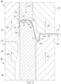
- the pressure concentrating forming surface 600 includes a plurality of "landings" 610.
- a "landing” is a limited area of the upper pressure sleeve forming surface 226.
- the pressure concentrating forming surface plurality of landings 610 includes between two and five substantially concentric landings 610A, 610B, 610C, 610D, 610E. That is, in an exemplary embodiment, the lower end of the upper pressure sleeve 218 includes an annular, i.e. generally circular, forming surface 226.
- the plurality of landings 610 are concentric portions of the annular forming surface 226 which clamp the blank 2.
- the landings 610 engage the blank 2.
- the areas between the landings 610 are upwardly offset relative to the landings 610 so that these areas do not engage the blank 2.
- the upper pressure sleeve forming surface 226 has a cross-sectional area that is much smaller than the cross-sectional area of the piston assembly 518 and/or the lower spring seat 554'.
- the pressure/area applied to the blank 2 by the upper pressure sleeve forming surface 226 is greater than the pressure/area acting on the piston assembly 518 and/or the lower spring seat 554'. That is, while the bias/force remains constant, the area upon which the bias/force acts is greater at the piston assembly 518 and/or the lower spring seat 554' compared to the area at the upper pressure sleeve forming surface 226.
- the area at the upper pressure sleeve forming surface 226 is smaller, the pressure per unit of area is greater.
- the increase in pressure per a unit of area is greater for a pressure concentrating forming surface 600. That is, the area of a pressure concentrating forming surface 600, as defined herein, is even smaller than the area upper pressure sleeve forming surface 226.
- the ratio of the total bias pressure to the clamping pressure is between about 1:10 to 1:50 or between about 1:20 and 1:40, or about 1:30.
- the clamping pressure is, in an exemplary embodiment, about at the elastic limit of the material being deformed.
- the material being deformed has a "thinning limit.” That is, as used herein, a “thinning limit” is the elastic limit of the material while under compression. That is, a material under compression may be placed under tension that exceeds the elastic limit of the material without tearing the material.
- the "thinning limit” is pressure that allows the material to thin by about 10% without tearing.
- the exemplary measurements above, e.g. the area of pressure surface 521, are for a tooling assembly 200 working on aluminum that is initially about 0.2083mm (0.0082 inch thick).
- the pressure concentrating forming surface 600 is structured to generate a clamping pressure that is about at the thinning limit of aluminum and to thin the aluminum so that the thickness of the material in the chuck wall 12 may be reduced to a thickness of about 0.1880mm (.0074 inch).
- use of the tooling assembly 200A described above includes introducing 1000 material between tooling assembly 200A, generating 1002 a total bias force within the tooling assembly 200A, clamping 1004 the material between an upper tool assembly 202 and a lower tool assembly 204, forming 1006 the material to include a center panel, a circumferential chuck wall, an annular countersink between the center panel and the circumferential chuck wall, and a curl extending radially outwardly from the chuck wall, and selectively stretching 1008 at least one predetermined portion of the shell relative to at least one other portion of the shell to provide a corresponding thinned portion of the shell.
Landscapes
- Engineering & Computer Science (AREA)
- Mechanical Engineering (AREA)
- Rigid Containers With Two Or More Constituent Elements (AREA)
- Shaping Metal By Deep-Drawing, Or The Like (AREA)
Claims (12)
- Werkzeug (200A) zum Ausbilden einer Hülle (4), wobei das Werkzeug (200A) Folgendes umfasst:eine obere Werkzeuganordnung (202), die eine obere Druckhülse (218) beinhaltet;wobei die obere Druckhülse (218) ein unteres Ende (227) beinhaltet;eine untere Werkzeuganordnung (204), die einen Formwerkzeugkernring (250) beinhaltet;wobei der Formwerkzeugkernring (250) ein oberes Ende (252) beinhaltet, wobei das obere Ende (252) des Formwerkzeugkernrings gegenüberliegend zum unteren Ende (227) der oberen Druckhülse angeordnet ist und das obere Ende (252) des Formwerkzeugkernrings eine innere, verjüngte Fläche (254), eine gerundete Innenfläche (256), eine im Wesentlichen horizontale Fläche (257) und eine gerundete Außenfläche (258) umfasst;wobei die untere Werkzeuganordnung (204) mit der oberen Werkzeuganordnung (202) zusammenwirkt, um dazwischen angeordnetes Material zu formen, um eine Mittelwand (6), eine Umfangsspannwand (12) eine ringförmige Versenkung (10) zwischen der Mittelwand (6) und der Umfangsspannwand (12) und eine Umbiegung (16), die sich radial von der Umfangsspannwand (12) nach außen erstreckt, zu beinhalten; undwobei die obere Werkzeuganordnung (202) und die untere Werkzeuganordnung (204) sich zwischen einer getrennten, ersten Position, in der die obere Werkzeuganordnung (202) von der unteren Werkzeuganordnung (204) beabstandet ist, und einer Formungsposition, in der die obere Werkzeuganordnung (202) unmittelbar benachbart zur unteren Werkzeuganordnung (204) ist, bewegen, um das Material von zumindest einem vorbestimmten Abschnitt der Hülle (4) relativ zu zumindest einem anderen Abschnitt der Hülle (4) zu strecken, wodurch ein entsprechender verdünnter Abschnitt bereitgestellt wird,dadurch gekennzeichnet, dassdas untere Ende (227) eine druckkonzentrierende Formungsoberfläche (600) definiert, welche mit dem Material in Eingriff gelangt, wenn die obere Werkzeuganordnung (202) und die untere Werkzeuganordnung (204) sich in der Formungsposition befinden, wobei die druckkonzentrierende Formungsoberfläche (600) zu einem Abschnitt der im Wesentlichen horizontalen Fläche (257) des Formwerkzeugkernrings gegenüberliegend angeordnet ist, sich aber nicht über die gerundete Innenfläche (256) des oberen Endes (252) des Formwerkzeugkernrings erstreckt.
- Werkzeug (200A) nach Anspruch 2, wobei die druckkonzentrierende Formungsoberfläche (600) einen verkleinerten Klemmbereich aufweist, wobei der verkleinerte Klemmbereich ein radial zusammenhängender ringförmiger Bereich ist, der sich über etwa 25-75 % der im Allgemeinen horizontalen Fläche (257) des oberen Endes (252) der Formwerkzeugkernrings erstreckt.
- Werkzeug (200A) nach Anspruch 2, wobei die druckkonzentrierende Formungsoberfläche (600) eine Vielzahl von Anlagebereichen (610) umfasst, wobei jeder Anlagebereich ein begrenzter Bereich der Formungsoberfläche (226) der oberen Druckhülse ist.
- Werkzeug (200A) nach Anspruch 3, wobei die Vielzahl von Anlagebereichen (610) der druckkonzentrierenden Formungsoberfläche zwischen zwei und fünf im Wesentlichen konzentrische Anlagebereiche (610A-610E) umfasst.
- Werkzeug (200A) nach Anspruch 1, wobei:die obere Werkzeuganordnung (202) eine obere Kopfplatte (206), einen Stufenkörper (214) und eine hybride Vorspannungserzeugungsanordnung (500) umfasst;der Stufenkörper (214) mit der Kopfplatte (206) gekoppelt ist, wobei der Stufenkörper (214) eine Druckkammer (516) definiert;die obere Druckhülse (218) beweglich in der Druckkammer (516) des Stufenkörpers angeordnet ist;die obere Druckhülse (218) zwischen einer ausgefahrenen, ersten Position, in der das untere Ende (227) der oberen Druckhülse weiter von der oberen Kopfplatte (206) beabstandet ist, und einer eingefahrenen, zweiten Position, in der das untere Ende (227) der oberen Druckhülse weniger von der oberen Kopfplatte (206) beabstandet ist, bewegbar ist;die hybride Vorspannungserzeugungsanordnung (500) mit der oberen Druckhülse (218) wirkgekoppelt ist; undwobei die hybride Vorspannungserzeugungsanordnung (500) die Bewegung der oberen Druckhülse (218) steuert, während die obere Werkzeuganordnung (202) und die untere Werkzeuganordnung (204) sich zwischen der ersten und der Formungsposition bewegen.
- Werkzeug (200A) nach Anspruch 5, wobei die hybride Vorspannungserzeugungsanordnung (500) eine Druckerzeugungsanordnung (510), eine mechanische Vorspannungsanordnung (550) und eine Anzahl von hybriden Komponenten (570) umfasst
- Werkzeug (200A) nach Anspruch 5, wobei die hybride Vorspannungserzeugungsanordnung (500) eine aktive hybride Vorspannungserzeugungsanordnung (502) ist.
- Werkzeug (200A) nach Anspruch 6, wobei:die Druckerzeugungsanordnung (510) strukturiert ist, um die Druckkammer (516) mit Druck zu beaufschlagen; unddie mechanische Vorspannungsanordnung (550) eine Anzahl von Federn (552) umfasst.
- Werkzeug (200A) nach Anspruch 8, wobei die Anzahl von Federn (552) innerhalb der Druckkammer (516) angeordnet ist.
- Werkzeug (200A) nach Anspruch 8, wobei:die hybride Vorspannungserzeugungsanordnung (500) eine Gesamtvorspannkraft erzeugt, während sich die obere Werkzeuganordnung (202) und die untere Werkzeuganordnung (204) zwischen der ersten und der zweiten Position bewegen;wobei die Druckerzeugungsanordnung (510) zwischen etwa 20 % und 30 % der Gesamtvorspannkraft erzeugt; undwobei die mechanische Vorspannungsanordnung (550) zwischen etwa 70 % und 80 % der Gesamtvorspannkraft erzeugt,wobei:die Druckerzeugungsanordnung (510) etwa 25 % der Gesamtvorspannkraft erzeugt; unddie mechanische Vorspannungsanordnung (550) etwa 75 % der Gesamtvorspannkraft erzeugt.
- Werkzeug (200A) nach Anspruch 8, wobei:die hybride Vorspannungserzeugungsanordnung (500) eine Gesamtvorspannkraft erzeugt, während sich die obere Werkzeuganordnung (202) und die untere Werkzeuganordnung (204) zwischen der ersten und der Formungsposition bewegen;wobei die Gesamtvorspannkraft über die obere Druckhülse (218) an die druckkonzentrierende Formungsoberfläche (600) kommuniziert wird;wobei die druckkonzentrierende Formungsoberfläche (600) strukturiert ist, um eine Klemmkraft auf ein Werkstück zu beaufschlagen; undwobei das Verhältnis der Gesamtvorspannkraft zur Klemmkraft zwischen etwa 20:1 und 40:1 beträgt.
- Werkzeug (200A) nach Anspruch 1, wobei:die obere Werkzeuganordnung (202) eine Gesamtvorspannkraft erzeugt, während sich die obere Werkzeuganordnung (202) und die untere Werkzeuganordnung (204) zwischen der ersten und der Formungsposition bewegen;wobei die Gesamtvorspannkraft über die obere Druckhülse (218) an die druckkonzentrierende Formungsoberfläche (600) kommuniziert wird;wobei die druckkonzentrierende Formungsoberfläche (600) strukturiert ist, um eine Klemmkraft auf ein Werkstück zu beaufschlagen; undwobei das Verhältnis der Gesamtvorspannkraft zur Klemmkraft zwischen etwa 20:1 und 40:1 beträgt.
Applications Claiming Priority (2)
| Application Number | Priority Date | Filing Date | Title |
|---|---|---|---|
| US14/722,187 US9975164B2 (en) | 2012-05-18 | 2015-05-27 | Container, and selectively formed shell, and tooling and associated method for providing same |
| PCT/US2016/026312 WO2016190969A1 (en) | 2015-05-27 | 2016-04-07 | Container, and selectively formed shell, and tooling and associated method for providing same |
Publications (3)
| Publication Number | Publication Date |
|---|---|
| EP3302845A1 EP3302845A1 (de) | 2018-04-11 |
| EP3302845A4 EP3302845A4 (de) | 2019-01-23 |
| EP3302845B1 true EP3302845B1 (de) | 2025-05-14 |
Family
ID=57394257
Family Applications (1)
| Application Number | Title | Priority Date | Filing Date |
|---|---|---|---|
| EP16800444.8A Active EP3302845B1 (de) | 2015-05-27 | 2016-04-07 | Behälter und selektiv geformte hülle sowie werkzeug und verfahren zur bereitstellung davon |
Country Status (6)
| Country | Link |
|---|---|
| EP (1) | EP3302845B1 (de) |
| JP (1) | JP6998216B2 (de) |
| CN (2) | CN107614140B (de) |
| BR (1) | BR112017025267B1 (de) |
| ES (1) | ES3033938T3 (de) |
| WO (1) | WO2016190969A1 (de) |
Families Citing this family (6)
| Publication number | Priority date | Publication date | Assignee | Title |
|---|---|---|---|---|
| US9975164B2 (en) | 2012-05-18 | 2018-05-22 | Stolle Machinery Company, Llc | Container, and selectively formed shell, and tooling and associated method for providing same |
| US20190351473A1 (en) * | 2018-05-15 | 2019-11-21 | Stolle Machinery Company, Llc | Method and apparatus for forming a can shell using a draw-stretch process |
| CN110125219B (zh) * | 2019-03-29 | 2020-12-08 | 武汉船用机械有限责任公司 | 薄壁异型件的加工装置 |
| CN116197287A (zh) * | 2021-11-30 | 2023-06-02 | 财团法人金属工业研究发展中心 | 壳件成形方法 |
| CN115475856A (zh) * | 2022-08-26 | 2022-12-16 | 中国航发南方工业有限公司 | 一种钣金成型小圆角的整形装置及方法 |
| WO2024260563A1 (de) * | 2023-06-22 | 2024-12-26 | Soudronic Ag | Verfahren zur herstellung eines blechdeckels |
Family Cites Families (21)
| Publication number | Priority date | Publication date | Assignee | Title |
|---|---|---|---|---|
| US3537291A (en) * | 1967-10-04 | 1970-11-03 | Reynolds Metals Co | Apparatus for and method of forming an end closure for a can |
| US3957005A (en) * | 1974-06-03 | 1976-05-18 | Aluminum Company Of America | Method for making a metal can end |
| US4722215A (en) * | 1984-02-14 | 1988-02-02 | Metal Box, Plc | Method of forming a one-piece can body having an end reinforcing radius and/or stacking bead |
| US4571978A (en) * | 1984-02-14 | 1986-02-25 | Metal Box P.L.C. | Method of and apparatus for forming a reinforced can end |
| CN1007412B (zh) * | 1985-08-13 | 1990-04-04 | 金属箱公共有限公司 | 加固罐头底盖成型方法和设备 |
| JP2815417B2 (ja) * | 1989-09-27 | 1998-10-27 | 富士重工業株式会社 | プレス型 |
| US5149238A (en) * | 1991-01-30 | 1992-09-22 | The Stolle Corporation | Pressure resistant sheet metal end closure |
| JPH08174093A (ja) * | 1994-12-27 | 1996-07-09 | Amada Co Ltd | パンチングマシンにおける板押え方法およびその装置 |
| DE29906170U1 (de) * | 1998-04-12 | 1999-09-23 | Schmalbach-Lubeca AG, 40880 Ratingen | Verschlußdeckel mit stapelfähigem Seitenspiel |
| WO2001087515A1 (en) * | 2000-05-17 | 2001-11-22 | Precision Machining Services, Inc. | High-speed forming of container shells |
| JP2002172432A (ja) * | 2000-12-06 | 2002-06-18 | Kobe Steel Ltd | プレス型装置 |
| JP2002336915A (ja) * | 2001-05-14 | 2002-11-26 | Mitsubishi Materials Corp | アルミニウム缶成形用絞り金型 |
| US6386013B1 (en) * | 2001-06-12 | 2002-05-14 | Container Solutions, Inc. | Container end with thin lip |
| JP4811559B2 (ja) | 2005-04-01 | 2011-11-09 | トヨタ自動車株式会社 | プレス成形型 |
| US7506779B2 (en) * | 2005-07-01 | 2009-03-24 | Ball Corporation | Method and apparatus for forming a reinforcing bead in a container end closure |
| US8141406B2 (en) * | 2008-10-09 | 2012-03-27 | Container Development, Ltd. | Method and apparatus for forming a can shell |
| US8573020B2 (en) * | 2010-09-20 | 2013-11-05 | Container Development, Ltd. | Method and apparatus for forming a can shell |
| US9149854B2 (en) * | 2011-05-04 | 2015-10-06 | Fca Us Llc | Stamping apparatus |
| US9573183B2 (en) | 2012-05-18 | 2017-02-21 | Stolle Machinery Company, Llc | Container, and selectively formed shell, and tooling and associated method for providing same |
| US9975164B2 (en) * | 2012-05-18 | 2018-05-22 | Stolle Machinery Company, Llc | Container, and selectively formed shell, and tooling and associated method for providing same |
| US20150050104A1 (en) * | 2013-08-19 | 2015-02-19 | Alfons Haar, Inc. | Method and apparatus for forming a can end with controlled thinning of formed portions of the can end |
-
2016
- 2016-04-07 WO PCT/US2016/026312 patent/WO2016190969A1/en not_active Ceased
- 2016-04-07 CN CN201680030515.3A patent/CN107614140B/zh active Active
- 2016-04-07 BR BR112017025267-8A patent/BR112017025267B1/pt active IP Right Grant
- 2016-04-07 CN CN201910094857.7A patent/CN109746301B/zh active Active
- 2016-04-07 JP JP2017561255A patent/JP6998216B2/ja active Active
- 2016-04-07 EP EP16800444.8A patent/EP3302845B1/de active Active
- 2016-04-07 ES ES16800444T patent/ES3033938T3/es active Active
Also Published As
| Publication number | Publication date |
|---|---|
| CN109746301A (zh) | 2019-05-14 |
| CN109746301B (zh) | 2021-05-04 |
| JP2018520877A (ja) | 2018-08-02 |
| BR112017025267B1 (pt) | 2021-06-01 |
| ES3033938T3 (en) | 2025-08-11 |
| CN107614140B (zh) | 2020-04-14 |
| JP6998216B2 (ja) | 2022-02-04 |
| EP3302845A4 (de) | 2019-01-23 |
| BR112017025267A2 (pt) | 2018-08-07 |
| EP3302845A1 (de) | 2018-04-11 |
| CN107614140A (zh) | 2018-01-19 |
| WO2016190969A1 (en) | 2016-12-01 |
Similar Documents
| Publication | Publication Date | Title |
|---|---|---|
| US10888913B2 (en) | Container, and selectively formed shell, and tooling and associated method for providing same | |
| US11826809B2 (en) | Container, and selectively formed cup, tooling and associated method for providing same | |
| EP3302845B1 (de) | Behälter und selektiv geformte hülle sowie werkzeug und verfahren zur bereitstellung davon | |
| EP2849900B1 (de) | Behälter und selektiv geformter deckel sowie werkzeug und verfahren zur bereitstellung davon | |
| AU2011240029B2 (en) | Can manufacture | |
| EP2531310B1 (de) | Dosenherstellung | |
| JP7366187B2 (ja) | 容器、及び選択的に形成されるカップ、ツーリング、並びにこれらを提供する関連方法 | |
| JP2021523021A (ja) | ドロー−ストレッチプロセスを用いて缶シェルを作る方法及び装置 | |
| US20230016790A1 (en) | Can end with a coined rivet, tooling assembly therefor and a method of forming | |
| JP2024020235A (ja) | 拡張可能リベットボタンを備えたシェル及びそのためのツーリング | |
| WO2019046224A1 (en) | INVERSE PRESERVE CAN RETAINER BOX | |
| JP7162665B2 (ja) | 拡張可能バブルを備えたシェル及びそのためのツーリング |
Legal Events
| Date | Code | Title | Description |
|---|---|---|---|
| STAA | Information on the status of an ep patent application or granted ep patent |
Free format text: STATUS: THE INTERNATIONAL PUBLICATION HAS BEEN MADE |
|
| PUAI | Public reference made under article 153(3) epc to a published international application that has entered the european phase |
Free format text: ORIGINAL CODE: 0009012 |
|
| STAA | Information on the status of an ep patent application or granted ep patent |
Free format text: STATUS: REQUEST FOR EXAMINATION WAS MADE |
|
| 17P | Request for examination filed |
Effective date: 20171124 |
|
| AK | Designated contracting states |
Kind code of ref document: A1 Designated state(s): AL AT BE BG CH CY CZ DE DK EE ES FI FR GB GR HR HU IE IS IT LI LT LU LV MC MK MT NL NO PL PT RO RS SE SI SK SM TR |
|
| AX | Request for extension of the european patent |
Extension state: BA ME |
|
| DAV | Request for validation of the european patent (deleted) | ||
| DAX | Request for extension of the european patent (deleted) | ||
| A4 | Supplementary search report drawn up and despatched |
Effective date: 20181220 |
|
| RIC1 | Information provided on ipc code assigned before grant |
Ipc: B21D 22/24 20060101ALI20181214BHEP Ipc: B21D 51/44 20060101ALI20181214BHEP Ipc: B21D 22/21 20060101AFI20181214BHEP |
|
| STAA | Information on the status of an ep patent application or granted ep patent |
Free format text: STATUS: EXAMINATION IS IN PROGRESS |
|
| 17Q | First examination report despatched |
Effective date: 20220323 |
|
| GRAP | Despatch of communication of intention to grant a patent |
Free format text: ORIGINAL CODE: EPIDOSNIGR1 |
|
| STAA | Information on the status of an ep patent application or granted ep patent |
Free format text: STATUS: GRANT OF PATENT IS INTENDED |
|
| INTG | Intention to grant announced |
Effective date: 20250205 |
|
| GRAS | Grant fee paid |
Free format text: ORIGINAL CODE: EPIDOSNIGR3 |
|
| GRAA | (expected) grant |
Free format text: ORIGINAL CODE: 0009210 |
|
| STAA | Information on the status of an ep patent application or granted ep patent |
Free format text: STATUS: THE PATENT HAS BEEN GRANTED |
|
| AK | Designated contracting states |
Kind code of ref document: B1 Designated state(s): AL AT BE BG CH CY CZ DE DK EE ES FI FR GB GR HR HU IE IS IT LI LT LU LV MC MK MT NL NO PL PT RO RS SE SI SK SM TR |
|
| REG | Reference to a national code |
Ref country code: GB Ref legal event code: FG4D |
|
| REG | Reference to a national code |
Ref country code: CH Ref legal event code: EP |
|
| P01 | Opt-out of the competence of the unified patent court (upc) registered |
Free format text: CASE NUMBER: APP_19892/2025 Effective date: 20250425 |
|
| REG | Reference to a national code |
Ref country code: IE Ref legal event code: FG4D |
|
| REG | Reference to a national code |
Ref country code: DE Ref legal event code: R096 Ref document number: 602016092245 Country of ref document: DE |
|
| REG | Reference to a national code |
Ref country code: ES Ref legal event code: FG2A Ref document number: 3033938 Country of ref document: ES Kind code of ref document: T3 Effective date: 20250811 |
|
| REG | Reference to a national code |
Ref country code: NL Ref legal event code: MP Effective date: 20250514 |
|
| PG25 | Lapsed in a contracting state [announced via postgrant information from national office to epo] |
Ref country code: FI Free format text: LAPSE BECAUSE OF FAILURE TO SUBMIT A TRANSLATION OF THE DESCRIPTION OR TO PAY THE FEE WITHIN THE PRESCRIBED TIME-LIMIT Effective date: 20250514 Ref country code: PT Free format text: LAPSE BECAUSE OF FAILURE TO SUBMIT A TRANSLATION OF THE DESCRIPTION OR TO PAY THE FEE WITHIN THE PRESCRIBED TIME-LIMIT Effective date: 20250915 |
|
| REG | Reference to a national code |
Ref country code: LT Ref legal event code: MG9D |
|
| PG25 | Lapsed in a contracting state [announced via postgrant information from national office to epo] |
Ref country code: GR Free format text: LAPSE BECAUSE OF FAILURE TO SUBMIT A TRANSLATION OF THE DESCRIPTION OR TO PAY THE FEE WITHIN THE PRESCRIBED TIME-LIMIT Effective date: 20250815 Ref country code: NO Free format text: LAPSE BECAUSE OF FAILURE TO SUBMIT A TRANSLATION OF THE DESCRIPTION OR TO PAY THE FEE WITHIN THE PRESCRIBED TIME-LIMIT Effective date: 20250814 |
|
| PG25 | Lapsed in a contracting state [announced via postgrant information from national office to epo] |
Ref country code: NL Free format text: LAPSE BECAUSE OF FAILURE TO SUBMIT A TRANSLATION OF THE DESCRIPTION OR TO PAY THE FEE WITHIN THE PRESCRIBED TIME-LIMIT Effective date: 20250514 Ref country code: PL Free format text: LAPSE BECAUSE OF FAILURE TO SUBMIT A TRANSLATION OF THE DESCRIPTION OR TO PAY THE FEE WITHIN THE PRESCRIBED TIME-LIMIT Effective date: 20250514 |
|
| REG | Reference to a national code |
Ref country code: AT Ref legal event code: MK05 Ref document number: 1794397 Country of ref document: AT Kind code of ref document: T Effective date: 20250514 |
|
| PG25 | Lapsed in a contracting state [announced via postgrant information from national office to epo] |
Ref country code: BG Free format text: LAPSE BECAUSE OF FAILURE TO SUBMIT A TRANSLATION OF THE DESCRIPTION OR TO PAY THE FEE WITHIN THE PRESCRIBED TIME-LIMIT Effective date: 20250514 |
|
| PG25 | Lapsed in a contracting state [announced via postgrant information from national office to epo] |
Ref country code: HR Free format text: LAPSE BECAUSE OF FAILURE TO SUBMIT A TRANSLATION OF THE DESCRIPTION OR TO PAY THE FEE WITHIN THE PRESCRIBED TIME-LIMIT Effective date: 20250514 |
|
| PG25 | Lapsed in a contracting state [announced via postgrant information from national office to epo] |
Ref country code: AT Free format text: LAPSE BECAUSE OF FAILURE TO SUBMIT A TRANSLATION OF THE DESCRIPTION OR TO PAY THE FEE WITHIN THE PRESCRIBED TIME-LIMIT Effective date: 20250514 |
|
| PG25 | Lapsed in a contracting state [announced via postgrant information from national office to epo] |
Ref country code: RS Free format text: LAPSE BECAUSE OF FAILURE TO SUBMIT A TRANSLATION OF THE DESCRIPTION OR TO PAY THE FEE WITHIN THE PRESCRIBED TIME-LIMIT Effective date: 20250814 |
|
| PG25 | Lapsed in a contracting state [announced via postgrant information from national office to epo] |
Ref country code: IS Free format text: LAPSE BECAUSE OF FAILURE TO SUBMIT A TRANSLATION OF THE DESCRIPTION OR TO PAY THE FEE WITHIN THE PRESCRIBED TIME-LIMIT Effective date: 20250914 |
|
| PG25 | Lapsed in a contracting state [announced via postgrant information from national office to epo] |
Ref country code: LV Free format text: LAPSE BECAUSE OF FAILURE TO SUBMIT A TRANSLATION OF THE DESCRIPTION OR TO PAY THE FEE WITHIN THE PRESCRIBED TIME-LIMIT Effective date: 20250514 |