EP3302341B1 - Self-ligating bracket - Google Patents
Self-ligating bracket Download PDFInfo
- Publication number
- EP3302341B1 EP3302341B1 EP16808190.9A EP16808190A EP3302341B1 EP 3302341 B1 EP3302341 B1 EP 3302341B1 EP 16808190 A EP16808190 A EP 16808190A EP 3302341 B1 EP3302341 B1 EP 3302341B1
- Authority
- EP
- European Patent Office
- Prior art keywords
- mesial
- distal
- center
- arm
- channel
- Prior art date
- Legal status (The legal status is an assumption and is not a legal conclusion. Google has not performed a legal analysis and makes no representation as to the accuracy of the status listed.)
- Active
Links
Images


Classifications
-
- A—HUMAN NECESSITIES
- A61—MEDICAL OR VETERINARY SCIENCE; HYGIENE
- A61C—DENTISTRY; APPARATUS OR METHODS FOR ORAL OR DENTAL HYGIENE
- A61C7/00—Orthodontics, i.e. obtaining or maintaining the desired position of teeth, e.g. by straightening, evening, regulating, separating, or by correcting malocclusions
- A61C7/12—Brackets; Arch wires; Combinations thereof; Accessories therefor
- A61C7/28—Securing arch wire to bracket
- A61C7/287—Sliding locks
Definitions
- the present disclosure relates to the field of orthodontics. More specifically, the present disclosure relates to self-ligating brackets.
- the present invention relates to a self-ligating bracket with the features of the introductory part of claim 1.
- Orthodontic treatment often involves at least a combination of an arch wire and brackets and/or buccal tubes that are used to secure the arch wire to the teeth of the patient.
- the arch wire is made of a resilient material that, if bent or deformed, will return to its previous shape.
- Dental malocclusions are treated by securing the arch wire to the patient teeth which are brought into a post-treatment alignment as the arch wire returns to its original shape. The corrective forces are transferred from the interactions between the arch wire and the arch wire slot of the bracket, through the bracket to the tooth.
- brackets are secured to the teeth of a patient and the brackets have an arch wire slot within which the arch wire is received.
- Elastomeric ligatures secure the arch wire within the arch wire slot of the bracket.
- Self-ligating brackets include a built-in mechanical ligature which eliminates the need for separate elastomeric ligatures to secure the arch wire to the bracket.
- Self-ligating brackets typically use a sliding and/or rotating clip or door that moves relative to the bracket body to occlude the arch wire slot.
- Self-ligating brackets are available as “active” brackets or “passive” brackets, which describe the way in which the arch wire may interact with the clip.
- Active self-ligating brackets include a clip in which an end or portion extends into an edgewise slot and resiliently applies a seating force against an arch wire in the facial-lingual dimension.
- the active self-ligating bracket retains the arch wire in the slot due to the mechanical strength of the clip itself.
- Active self-ligating brackets provide more control of the interactive forces between the clip and the arch wire, but can increase friction between the arch wire and the clip, which may reduce the transfer of this force to the tooth.
- Passive self-ligating brackets include a clip that extends across and beyond the arch wire slot and is fixed or restrained against movement in the facial-lingual dimension.
- the passive self-ligating bracket when closed, effectively forms a tube defined by the slot and the clip within which an arch wire with a diameter smaller than a diameter of the formed tube can slide. For this reason, in some applications, the clip of a passive self-ligating bracket is called a door.
- a self-ligating bracket including a bracket body with a mesial and a distal channel.
- a spring clip includes a distal arm with a distal arm body and a distal finger and a mesial arm with a mesial arm body and a mesial finger.
- the spring clip is slidably secured within the bracket body by a sliding engagement of the distal arm with the distal channel and the mesial arm with the mesial channel.
- the spring clip is movable between an open position and a closed position wherein in the open position, the arch wire slot is unobstructed and in the closed position the mesial finger and distal finger extend into and across the arch wire slot to occlude the arch wire slot.
- Document US 2011/076633 A1 discloses a self-ligating orthodontic bracket with an archwire slot, two outer tracks extending in an occlusal-gingival direction on the outer lateral surfaces of the bracket, and a vertical trough extending in an occlusal-gingival direction between the outer tracks.
- a clip has two parallel outer arms and a central tongue between the outer arms.
- the outer tracks of the bracket slidably engage the outer arms of the clip and the central tongue is slidably engaged by the vertical trough of the bracket, thereby allowing the clip to slidably move between an open position in which the outer arms of the clip are retracted from the archwire slot to allow an archwire to be placed into the archwire slot, and a closed position in which the outer arms of the clip extend across the archwire slot to retain the archwire in the archwire slot.
- the object of the present invention is to provide an improved self-ligating bracket.
- the self-ligating bracket according to the invention first of all includes a bracket body.
- the bracket body includes a mesial side and a distal side.
- the bracket body includes an arch wire slot that extends from the mesial side to the distal side of the bracket body.
- a mesial channel extends into the bracket body.
- a center channel extends into the bracket body between the mesial channel and the distal channel.
- a spring clip includes a distal arm which includes a distal arm body and a distal finger.
- the spring clip includes a mesial arm which includes a mesial arm body and a mesial finger.
- the spring clip includes a center arm which includes a first center arm bar and a second center arm bar.
- the spring clip further includes a base bar.
- the spring clip is positioned on the bracket body.
- the first center arm bar and the second center arm bar are connected by a center arm end bar.
- the first center arm bar, the second center arm bar, the center arm end bar and the base bar are defining a center opening.
- the spring clip is movable between an open position and a closed position. In the open position, the arch wire slot is unobstructed and in the closed position the distal finger, the mesial finger, and the center arm extend into and across the arch wire slot to occlude the arch wire slot.
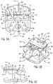
- Figs. 1-6 all depict various views of a first exemplary embodiment of a self-ligating bracket 10.
- the self-ligating bracket 10 generally includes a bracket body 12, a spring clip 14, and a bracket cap 16.
- a bonding pad 18 is secured to the bracket body 12.
- the bonding pad 18 may be exemplarily secured to the bracket body 12 by braising or welding.
- the bonding pad 18 may be secured to the bracket body 12 by being integral to one another and being exemplarily formed by casting or milling, although it will be understood that alternative techniques of manufacturing the bracket body 12 and bonding pad 18 may be used.
- the bonding pad 18 may be formed or contoured such as to be secured to a tooth of a patient's dentition.
- the self-ligating bracket 10 exemplarily includes a distal side 20, a mesial side 22, a gingival side 24, and an occlusal side 26. It will be recognized that these designations are relative and informational and alternative embodiments may be positioned in other orientations within the mouth of the patient while remaining within the scope of the embodiments as disclosed herein.
- Figs. 1A-C depict various views of the first exemplary embodiment of the self-ligating bracket 10 in a closed configuration in which the spring clip 14 is moved to a closed position that occludes an arch wire slot 28.
- Figs. 2A-C depict various views of the first exemplary embodiment of the self-ligating bracket 10 in an open configuration in which the spring clip 14 is moved to a position in which the arch wire slot 28 is accessible to receive an arch wire (not depicted).
- the spring clip 14 is in the open position away from the arch wire slot 28 and the arch wire slot 28 is able to receive an arch wire.
- the spring clip 14 When the self-ligating bracket 10 is in the closed configuration, the spring clip 14 is in a closed position extending across and into the arch wire slot 28 in a manner that operates to retain the arch wire during use to orthodontically treat the dentition of a patient. Specific features and interaction within the embodiment will be described in further detail herein with respect to Figs. 4-6 .
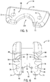
- Fig. 4A is a top view of a spring clip 14.
- Fig. 4B is a perspective view of the spring clip 14.
- the spring clip 14 includes a distal arm 30, a mesial arm 32, and a center arm 34.
- the distal arm 30 further includes a distal arm body 36 and a distal finger 38.
- the distal arm 30 terminates in a distal arm end 39.
- the distal finger 38 is connected to the distal arm body 36 by a distal transition portion 40.
- the distal transition portion 40 is formed as an S-curve between the distal arm body 36 and the distal finger 38, although it will be recognized that the distal transition portion 40 may take a variety of other shapes or forms while staying within the scope of the present disclosure.
- the distal finger 38 is planar and extends in a different plane than the distal arm body 36. In some embodiments, the distal finger 38 may extend parallel to the distal arm body 36. In other embodiments, the distal finger 38 may extend at another angle or curvature.
- the mesial arm 32 similarly includes a mesial arm body 42 connected to a mesial finger 44 by a mesial transition portion 46. The mesial arm 32 terminates in a mesial arm end 45. In an embodiment, the mesial arm 32 is constructed in similar manners as described above with respect to the distal arm 30.
- the distal arm 30 includes a distal projection 48.
- the distal projection 48 extends interior to the self-ligating bracket 10 from the distal finger 38.
- the mesial arm 32 further includes a mesial projection 50 that extends into the self-ligating bracket 10 exemplarily from the mesial finger 44.
- the center arm 34 is exemplarily constructed of two generally opposed center arm bars 52 connected by a center arm end bar 54.
- the center arm 34 terminates in a center arm end 55.
- the center arm end bar 54 exemplarily extends across and connects gingival ends 56 of the respective center arm bars 52.
- the center arm end bar 54 exemplarily extends in the same plane as the distal finger 38 and mesial finger 44. In still further exemplary embodiments, the center arm end bar 54 extends in the same plane as the distal projection 48 and the mesial projection 50.
- the center arm bars 52 exemplarily further include center transition portions 58, which are exemplarily S-curves.
- the spring clip 14 further includes a base bar 60 that may generally extend along a length of the spring clip 14 in the mesial-distal dimension.
- the distal arm 30, mesial arm 32, and center arm 34 all exemplarily extend away from the base bar 60.
- a total width W1 of the spring clip 14 between the distal arm 30 and the mesial arm 32 exemplarily coincides with the bracket body 12 in total width in the mesial-distal dimension.
- a distal edge 37 of the distal arm 30, and particularly the distal finger 38 is aligned with a distal side 20 of the bracket body 12 and a mesial edge of the mesial arm 32, and particularly the mesial finger 44 is aligned with a mesial side 22 of the bracket body 12.
- the distal arm 30 and mesial arm 32 apply their restraining forces on an arch wire starting at the respective distal and mesial ends of the arch wire slot 28.
- the center arm 34 more specifically, the center arm end bar 54 provides the restraining force on an arch wire at the center of the arch wire slot 28, and similarly the center of the bracket 12.
- the distal finger 38 has a width W2
- the center arm end bar 54 has a width W3
- the mesial finger 44 has a width W4.
- These widths represent the portion of the spring clip 14 that are configured to engage an arch wire in the slot 28.
- a combined width (W2+W3+W4), while necessarily less than or equal to W1, represents the amount of the arch wire slot 28 that is occluded when the clip 14 is in the closed position.
- the combined width is 60% or more of W1.
- the distal projection 48 increases W2 beyond the width of the distal arm body 36 and the mesial projection 50 increases W4 beyond the width of the mesial arm body 42 and the combined width is a greater percentage of W1.
- the distal and mesial projections 48, 50 are at least twice as wide as the respective widths of the distal arm body 36 and the mesial arm body 42 and the combined width is 80% or more of W1.
- the combined width is 85% or more of W1.
- the combined width is 90% or more of W1.
- the center arm bars 52 and the center arm end bar 54 exemplarily define a center opening 62.
- the center opening 62 exemplarily includes a first end 64, which may be generally flat as defined by the center arm end bar 54 and a second end 66 that may be rounded in shape and defined by a curve formed into the center arm bars 52 and base bar 60. It will be recognized that the center opening 62 may exemplarily take other shapes while still remaining within the scope of the present disclosure.
- Fig. 5 is a perspective view of an exemplary embodiment of a bracket cap 16 as will be described in further detail herein.
- the bracket cap 16 has a generally planar top surface 68.
- the bracket cap 16 includes an arch wire slot side 70. Opposite the arch wire slot side 70, the bracket cap 16 ends in two tie wing caps 72.
- the bracket cap 16 is configured to matingly engage the bracket body 12 in the manners as depicted in Figs. 1-3 . In such engagement, the arch wire slot side 70 is aligned with an occlusal wall 27 of the arch wire slot 28 in the bracket body 12 and each of the tie wing caps 72 align with respective tie wings 74 of the bracket body 12.
- the bracket cap 16 further includes post holes 76 that extend through the bracket caps 16 and are configured to engage posts 78 on the bracket body 12 as described in further detail herein.
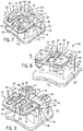
- Fig. 6 depicts various views of an exemplary embodiment of a bracket body 12.
- the bracket body 12 further includes a plurality of stop projections 94, exemplarily gingival stop projections 80 and occlusal stop projections 82 that respectively extend into a distal channel 84 within which the distal arm (not depicted) of the spring clip 14 slides and the mesial channel 86 within which the mesial arm (not depicted) of the spring clip 14 slides.
- the stop projections 80, 82 resiliently engage the distal projection 48 and the mesial projection 50 of the spring clip 14 ( Fig. 4 ).
- the engagement of the spring clip 14 distal projection and mesial projection with the stop projection 80 and 82 of the bracket body 12 defines and open position of the spring clip 14.
- engagement of the distal finger 38 and mesial finger 44 with respective gingival sides 88 of the arch wire slot 28 as well as engagement of the base bar 60 with occlusal end 90 of the occlusal stop projections 82 define the closed position of the spring clip 14.
- the bracket body 12 further includes a center channel 92 within which the center arm 34 of the spring clip 14 slides, as depicted in Figs. 1-3 .
- a stop projection 94 is located within the center channel 92 and exemplarily extends upwards from a center channel floor 96 which is the surface that the center arm 34 of the spring clip 14 slidingly engages.
- the stop projection 94 is exemplarily dimensioned such that it is can be slidingly received within the center opening 62 of the spring clip 14. When the center opening 62 of the spring clip 14 is arranged over the stop projection 94, the center arm 34 is slidably received within the center channel 92.
- the stop projection 94 extends through the center opening 62 where when the spring clip 14 is in the open position, the stop projection 94 engages the first end 64 of the center opening 62, which may be embodied by the center arm end bar 54 of the center arm 34.
- the engagement of the stop projection 94 with the center arm end bar 54 further defines the open position of the spring clip 14 and prevents complete removal of the spring clip 14 beyond the defined open position.
- the bracket body 12 further includes shoulders 98 on the occlusal wall 27 of the arch wire slot 28 which effectively transition each of the distal channel 84, mesial channel 86, and center channel 92 into the ach wire slot 28.
- the respective transition portions 40, 46, and 58 of the distal arm 30, mesial arm 32, and center arm 34 are exemplarily shaped as S-curves which, due to the resilient material from which the spring clip 14 is constructed, generally flatten as the spring clip 14 is moved into the open position and withdrawn into the respective distal channel 84, mesial channel 86, or center channel 92.
- distal channel 84, mesial channel 86, and center channel 92 are further defined on the labial side by the bracket cap 16 secured to the bracket body 12. As the spring clip 14 is moved into the closed position, the S-curves of the transition portions return to their normal configuration and create a biasing force against the shoulders 98 to retain the spring clip 14 in the closed position.
- the arms are further reinforced against the arch wire escaping the arch wire slot 28 when the spring clip 14 is in the closed position.
- the cap 16 provides a resilient force against each of the arms 30, 32, 34 in the facial-lingual dimension. This creates a short moment arm about which any force in the facial-lingual dimension from the arch wire against any arms 30, 32, 34 is resisted. The short moment arm increases the strength of the arms to resist this force.
- the arch wire slot side 70 of the cap16 may be in alignment with the occlusal wall 27 of the arch wire slot 28 which further minimizes this moment arm.
- a similar configuration and embodiment with similar advantages may be implemented in the embodiment of the bracket shown and described with respect to Figs. 7-11 , although in such embodiment, the caps 114 engage the mesial arm 32 and distal arm 30.
- the bracket cap 16 further includes a tool cut out 100 that extends between the tie wing cap 72.
- the tool cut out 100 may exemplarily be defined as a complex curve defined by three curved sections comprising at least two radii.
- the second end 66 of the center opening 62 of the spring clip 14 is aligned with the tool cut out 100 to facilitate access by an orthodontist's tool tip (not depicted) with the second end 66 of the center opening 62 such that the orthodontist can apply an opening force with the orthodontic tool tip to overcome the exemplary biasing forces, of the transition portion of the spring clip arms against the shoulders 98 of the bracket body 12 as well as the distal and mesial projections 48, 50 against the respective gingival stop projections 80 of the base, to move the spring clip 14 into the open position.
- the orthodontic tool creates a lever between the bracket body 12 and the spring clip 14 to move the spring clip 14 from the closed position to the open position.
- the tool tip extends through the center opening 62 and engages the bracket body 12 through the center opening 62.
- the orthodontist uses a twisting or rotating movement to place a force in the gingival direction against the bracket body 12 and a force in the occlusal direction against the spring clip 14. These forces overcome the biasing forces of the spring clip 14 in the closed position to move the spring clip 14 into the open position.
- this may provide improved patient comfort as the forces from the tool generally oppose one another creating less force felt by the patient in contrast to an embodiment wherein the tool tip only engages the spring clip 14 with the force in the occlusal direction.
- the above described structural features of the first embodiment of the self-ligating bracket 10 achieve the desirable feature of providing a self-ligating bracket 10 which includes a spring clip 14 that is captured between the bracket body 12 and the bracket cap 16.
- the spring clip 14 is positioned on the bracket body 12, exemplarily in the closed position with the distal, mesial, and center arms 30, 32, 34 positioned respectively in the distal, mesial, and center channels 84, 86, 92.
- the bracket cap 16 is secured to the bracket body 12, securing the spring clip 14 moveably between the bracket body 12 and the bracket cap 16.
- the bracket cap 16 can be secured, exemplarily by welding or braising to the bracket body 12.
- Fig. 3 shows the bracket cap 16 secured to the bracket body 12 and in contact with the top of the stop projection 94.
- the distal channel 84, center channel 92, (and mesial channel 86) are exemplarily the same height as the thickness of the spring clip 14 such that the spring clip 14 is slidable within the respective channels.
- the bracket cap 16 traps the spring clip 14 in slidable engagement between the bracket cap 16 and bracket body 12. The spring clip 14 cannot be removed from the joined bracket body 12 and the bracket cap 16 because of the engagement of the center arm end bar 54 with the stop projection 94 when the spring clip 14 is moved into the open position and the securement of the bracket cap 16 over the center channel 92.
- Fig. 3 is a side sectional view taken along line 3-3 of Fig. 1A depicting an exemplary embodiment of the self-ligating bracket 10 in the closed configuration.
- the arch wire slot 28 is defined by an occlusal wall 27, a gingival wall 29, and a bottom wall 31.
- the arch wire slot 28 has a width of 0.022 inches for which coincides with a larger diameter of a standard rectangular arch wire; however, it will be recognized that other dimensions or configurations of the arch wire slot 28 may be used as disclosed in embodiments herein.
- the respective distal arm 30, mesial arm 32, and center arm 34 bend at respective distal transition portion 40, mesial transition portion 46, and center transition portions 58 such that the distal finger 38, mesial finger 44, and center arm 34 are located into the arch wire slot 28 at a position closer to the bottom 31 of the arch wire slot 28 than the rest of the spring clip 14.
- a distance D1 between the bottom of the respective fingers 38, 44 and center arm 34 of the spring clip 14 and the bottom 31 of the arch wire slot 28 defines a minimum diameter of arch wire required for active engagement of the arch wire by the spring clip 14.
- an active self-ligating bracket 10 may be one in which a cross-sectional dimension of a lumen defined by the arch wire slot 28 and the spring clip 14 in the closed position is smaller than a cross-sectional dimension of at least one arch wire for which the arch wire slot 28 is configured to receive.
- a passive self-ligating bracket 10 may be one in which a cross-sectional dimension of the lumen defined by the arch wire slot 28 and the spring clip 14 in the closed position is greater than a cross-sectional dimension of a largest arch wire for which the arch wire slot 28 is configured to receive.
- the spring clip 14 of the passive self-ligating bracket 10 therefore does not engage any size of arch wire during treatment.
- Passive self-ligating brackets 10 provide less control over bracket arch wire interaction, but do so with minimal friction (all else being equal) compared to elastomeric ligations and active spring clips 14 which may improve transfer of the corrective force to the tooth.
- the lumen of a passive self-ligating bracket 10 may further be defined by a rigid ledge or other portion of the bracket body 12 that engages the spring clip 14 to define the minimum distance between the bottom of the arch wire slot 28 and the spring clip 14 in the closed position.
- the engagement of the spring clip 14 with this structure of the bracket body 12 may limit this minimum distance independent of the shape or other physical properties of the spring clip 14 itself.
- a bracket may be designed for use with arch wires having a diameter in the facial-lingual dimension of 0.018 inch and with arch wires having a diameter in the facial-lingual dimension of 0.022 inch.
- an active self-ligating bracket 10 embodiment may be one with the aforementioned distance (D1) in the lumen is less than or equal to 0.022, while the spring clip 14 in the closed position is capable of flexing to a distance (D1) of at least 0.022 inch while a passive self-ligating bracket 10 is one in which the aforementioned distance (D1) in the lumen is greater than 0.022 inch, independent of the flexibility or rigidity of the spring clip 14.
- At least one of the end 39 of the distal arm 30, the end 45 of the mesial arm 32, and the end 55 of the center arm end bar 54 engages the gingival wall 29 of the arch wire slot 28 when the spring clip 14 is in the closed position and when the spring clip 14 is in the open position, the ends 39, 45, 55 are retracted into the bracket body 12 occlusally of the occlusal wall 27 of the arch wire slot 28.
- at least one of the end 39 of the distal arm 30, the end 45 of the mesial arm 32, and the end 55 of the center arm end bar 54 extend gingivally past a plane of the gingival wall 29, or end occlusally of the gingival wall 29. In either case, when the spring clip 14 is in the open position, the respective ends 39, 45, 55 of the arms 30, 32 and of the center arm end bar 54 are retracted occlusally of the occlusal wall 27.
- Some embodiments of the features described present additional advantages in that self-ligating bracket 10 spring clips 14 are typically tiny pieces of metal that if removed from engagement with the rest of the bracket, may become lost in a patient's mouth, swallowed by a patient, or cause abrasion to the inside of the patient's mouth. Therefore, a bracket that securely retains the spring clip 14 when the spring clip 14 is in the open position is beneficial. Additionally, retention of the spring clip 14 in engagement with the rest of the bracket can minimize the risk of damage to the spring clip 14 as the spring clip 14 cannot be moved out of position.
- Figs. 7-11 depict a second exemplary embodiment of a self-ligating bracket 110. It will be recognized that in Figs. 7-11 similar reference numerals as used and described above with respect to Figs. 1-6 are further used herein to identify similar structures.
- the self-ligating bracket 110 includes a bracket body 112 a spring clip 14 and a bonding pad 18.
- the bracket body 112 includes an arch wire slot 28 and tie wings 74.
- the arch wire slot 28 is defined by an occlusal wall 27, a gingival wall 29, and a bottom wall 31.
- the occlusal wall 27, gingival wall 29, and bottom wall 31 define a largest diameter or arch wire that can be accepted into the bracket 110.
- the bracket body 112 includes gingival stop projections 80 and occlusal stop projections 82.
- the gingival stop projections 80 and occlusal stop projections 82 respectively extend labially for at least the thickness of the spring clip 14 to define the distal channel 84 and mesial channel 86 in the labial dimension.
- the gingival stop projections 80 and occlusal stop projections 82 extend into the distal channel 84 within which the distal arm 30 of the spring clip 14 is slidingly received and the mesial channel 86 from which the mesial arm 32 of the spring clip 14 is slidably received.
- the bracket body 112 further includes a center channel 92 within which the center arm 34 of the spring clip 14 slidingly moves.
- the center arm 34 includes center arm bars 52 which terminate at a center arm end bar 54 connecting gingival ends 56 of respective center arm bars 52.
- the spring clip 14 further defines a center opening 62 bounded by the center arm bars 52, the center arm end bar 54 and the base bar 60 of the spring clip 14.
- the center opening 62 is exemplarily defined between a first end 64 and a second end 66.
- the first end 64 and second end 66 of the center opening 62 are exemplarily curved shaped. It will be recognized, however, that other shapes of the first end 64 and second end 66 may be used in this embodiment and in other embodiments while remaining within the scope of the present disclosure.
- the distal arm 30 includes a distal transition portion 40
- the mesial arm 32 includes a mesial transition portion 46
- the center arm 34 includes center transition portions 58.
- Each of the transition portions 40, 46, and 58 are exemplarily shaped as S-curves while other configurations will be recognized from the present disclosure.
- the bracket body 112 includes tie wing caps 114 that are integral components of the bracket body 112.
- the tie wing caps 114 exemplarily extend from the gingival stop projections 80 and the occlusal stop projections 82 and cover above the respective distal channel 84 and mesial channel 86, while leaving the center channel 92 exemplarily exposed.
- the bracket body 112 further includes a stop projection 116 that extends from a channel floor 96 of the center channel 92.
- the stop projection 116 further includes a gingival shoulder 118 and an occlusal ramp 120.
- the self-ligating bracket 110 is assembled by inserting the spring clip 14 into the occlusal side of the bracket body 112 and slide the distal arm 30 and mesial arm 32 within the respective distal channel 84 and mesial channel 86 of the bracket body 112.
- the distal arm 30 and mesial arm 32 deform in the mesial-distal dimension so that the respective distal projection 48 and mesial projection 50 can pass around first the occlusal stop projection 82 and later the gingival stop projection 80, when the spring clip 14 is moved into the closed position.
- the center arm end bar 54 engages the occlusal ramp 120 of the stop projection 116.
- the occlusal ramp 120 deforms the center arm 34 outward in an exemplary facial direction until the first end 64 of the center opening 62 passes over the gingival shoulder 118 of the stop projection 116.
- the respective transition portions 40, 58, and 46 of the spring clip arms pass over the shoulders 98 and the distal finger 38, center arm end bar 54, and mesial finger 44 extend into and across the arch wire slot 28 as the transition portions 40, 46, and 58 return to their normal position. In this position, the distal finger end 39 and mesial finger end 45 engage the gingival wall 29 of the arch wire slot 28.
- the distal arm 30 and mesial arm 32 operate in the same manner as described above with respect to Figs. 1-6 .
- the center arm 34 operates in an alternative manner as the center arm 34 is not retained in engagement with the bracket body 112 by the bracket cap 16 as in the first embodiment ( Figs. 1-6 ). Rather, as the transition portions 58 of the center arm 34 are deformed to move past the shoulder 98 from the closed position to the open position, an inward or exemplarily lingual force is placed on the center arm end bar 54 in conjunction with the engagement of the gingival shoulder 118 against the first end 64 of the center opening 62.
- the spring clip 14 is held from any further movement in the exemplary occlusal direction as such movement would require additional deforming forces both against the center arm end bar 54 in the facial direction to move past the stop projection 116 and against the distal arm 30 and mesial arm 32 outwardly in the mesial-distal dimension to respectively move the distal projection 48 and mesial projection 50 out of respective engagement with the occlusal stop projections 82.
- the spring clip 14 is effectively locked into engagement with the bracket body 112 and is not removable without damaging one or more components of the self-ligating bracket 110.
- the self-ligating bracket 110 as described herein present advantages over current self-ligating bracket solutions by providing a spring clip 1 that is moveably secured to the bracket body 112 in a manner that prevents its removal.
- Self-ligating brackets 110 as described herein may further provide improved active ligation by separately engaging an arch wire positioned in the arch wire slot 28 at at least two, and in some embodiments three, locations: the distal end of the slot, the mesial end of the slot, and at the center of the slot.
- the arch wire necessarily experiences uneven interaction with the arch wire slot 28 and the spring clip 14. This imbalance in interactions direct the tooth to the desired corrected position. Only after the tooth is in the corrected position (as can be achieved with a particular arch wire dimension) and can freely move within the arch wire slot 28. Therefore, the spring clips 14 as disclosed herein are able to individually provide active force against the arch wire with each slot when torque on the tooth/bracket causes the arch wire to unevenly interact with the spring clip 14. The separate arms engage the wire independently and therefore maintain engagement by each arm during treatment.
- Self-ligating brackets 110 as described herein provide the above-mentioned at least two and in some embodiments three independent areas of active force, but also, with the center arm 34, and distal and mesial projections 48, 50 of the distal and mesial fingers 38, 44, engage the arch wire across a substantial width of the total arch wire slot 28 width.
- Embodiments as disclosed herein may engage the arch wire across greater than 60%, 80%, 85%, or greater than 90% of the arch wire slot 28 width.
- the brackets disclosed herein may provide three independent areas of active ligating force, such forces are also applied across a substantial portion of the width of the arch wire slot 28 and bracket.
- the distal projections 48 and mesial projections 50 serve multiple functions of retaining the spring clip 14 in the open position (by engagement with the gingival projections), retaining the spring clip 14 to the bracket body 112 (by engagement with the occlusal projections 82), and increasing the area of engagement with the arch wire.
- brackets 110 may similarly exemplarily refer to buccal tubes, convertible orthodontic appliances, and/or other orthodontic appliances which may include a self-ligating clip as described herein.
Applications Claiming Priority (2)
| Application Number | Priority Date | Filing Date | Title |
|---|---|---|---|
| US201562172548P | 2015-06-08 | 2015-06-08 | |
| PCT/US2016/036452 WO2016200944A1 (en) | 2015-06-08 | 2016-06-08 | Self-ligating bracket |
Publications (3)
| Publication Number | Publication Date |
|---|---|
| EP3302341A1 EP3302341A1 (en) | 2018-04-11 |
| EP3302341A4 EP3302341A4 (en) | 2018-12-26 |
| EP3302341B1 true EP3302341B1 (en) | 2020-01-01 |
Family
ID=57451700
Family Applications (1)
| Application Number | Title | Priority Date | Filing Date |
|---|---|---|---|
| EP16808190.9A Active EP3302341B1 (en) | 2015-06-08 | 2016-06-08 | Self-ligating bracket |
Country Status (6)
| Country | Link |
|---|---|
| US (3) | US10080628B2 (ja) |
| EP (1) | EP3302341B1 (ja) |
| JP (1) | JP6976174B2 (ja) |
| CN (2) | CN117814936A (ja) |
| HK (1) | HK1249841A1 (ja) |
| WO (1) | WO2016200944A1 (ja) |
Families Citing this family (10)
| Publication number | Priority date | Publication date | Assignee | Title |
|---|---|---|---|---|
| EP3345567B1 (en) | 2010-12-08 | 2023-08-02 | Strite Industries Ltd. | Orthodontic gripping device |
| CN117814936A (zh) * | 2015-06-08 | 2024-04-05 | 美国正畸公司 | 齿列矫正托架绑带的方法 |
| USD854163S1 (en) * | 2017-02-09 | 2019-07-16 | Centro de Innovacion en Ortodoncia, S.L. | Dental appliance |
| CN107019569A (zh) * | 2017-05-19 | 2017-08-08 | 吉利 | 自锁托槽及其开启方法 |
| CN109549721A (zh) * | 2017-09-25 | 2019-04-02 | 金华市柯帝夫医疗器械科技有限公司 | 一种自锁托槽 |
| US11147653B2 (en) | 2020-02-11 | 2021-10-19 | Tp Orthodontics Inc. | Orthodontic bracket having a movable ligating door |
| US11324573B2 (en) | 2020-07-03 | 2022-05-10 | Aadvance Technologies, Llc | Orthodontic device |
| USD1022215S1 (en) | 2022-07-08 | 2024-04-09 | American Orthodontics Corporation | Orthodontic bonding pad |
| USD1022216S1 (en) | 2022-07-08 | 2024-04-09 | American Orthodontics Corporation | Orthodontic bonding pad |
| USD1022217S1 (en) | 2022-07-08 | 2024-04-09 | American Orthodontics Corporation | Orthodontic bonding pad |
Family Cites Families (103)
| Publication number | Priority date | Publication date | Assignee | Title |
|---|---|---|---|---|
| US2549528A (en) | 1949-08-12 | 1951-04-17 | Baker & Co Inc | Orthodontic device |
| US2671964A (en) | 1952-12-10 | 1954-03-16 | Russell Harry John | Orthodontic appliance |
| US3131474A (en) | 1961-09-05 | 1964-05-05 | Unitek Corp | Orthodontic appliance |
| US4197642A (en) | 1977-09-29 | 1980-04-15 | Melvin Wallshein | Bent wire orthodontic spring clip |
| US4248588A (en) | 1979-04-27 | 1981-02-03 | Hanson Gustaf H | Orthodontic bracket and arch wire |
| US4419078A (en) | 1981-05-20 | 1983-12-06 | Pletcher Erwin Carroll | Orthodontic bracket |
| US4492573A (en) | 1984-03-27 | 1985-01-08 | Augusta Developments Inc. | Orthodontic bracket |
| CA1279215C (en) | 1984-04-23 | 1991-01-22 | Johnson & Johnson Dental Products Company | Crystalline alumina orthodontic bracket |
| US5094614A (en) | 1991-03-08 | 1992-03-10 | Wildman Alexander J | Miniature self-locking labial bracket |
| US5322435A (en) | 1992-07-23 | 1994-06-21 | Pletcher Erwin Carroll | Orthodontic bracket |
| US5630715A (en) | 1993-01-21 | 1997-05-20 | Voudouris; John C. | Orthodontic bracket with an engagement mechanism for retaining an archwire |
| US5439378A (en) * | 1993-04-08 | 1995-08-08 | Damon Family Limited Partnership | Orthodontic bracket assembly and method of installation |
| US5429500A (en) | 1993-04-08 | 1995-07-04 | Damon Family Limited Partnership | Self-locking orthodontic bracket |
| US5466151A (en) | 1993-04-08 | 1995-11-14 | Damon Family Limited Partnership | Spring-locked orthodontic bracket |
| US5275557A (en) | 1993-04-08 | 1994-01-04 | Damon Dwight H | Self-locking orthodontic bracket |
| DE4407100C2 (de) | 1994-03-03 | 1997-11-13 | Wolfgang Dr Med Heiser | Bracket für kieferorthopädische Behandlungen |
| US5913680A (en) | 1994-03-07 | 1999-06-22 | Voudouris; John C. | Orthodontic bracket |
| US5474445A (en) | 1994-03-07 | 1995-12-12 | John Voudouris | Self-engaging twin edge-wise orthodontic bracket with pivotal latch |
| US5857850A (en) | 1994-03-07 | 1999-01-12 | Voudouris; John C. | Orthodontic appliance |
| US6257883B1 (en) | 1994-03-07 | 2001-07-10 | John C. Voudouris | Orthodontic bracket |
| US5908293A (en) * | 1994-03-07 | 1999-06-01 | Voudouris; John C. | Orthodontic bracket |
| US5474446A (en) | 1994-07-06 | 1995-12-12 | Wildman; Alexander J. | Miniature self-locking labial bracket with cam-release closure member |
| JP3408683B2 (ja) | 1995-12-01 | 2003-05-19 | 株式会社インジェックス | 歯科用器具 |
| US5711666A (en) | 1996-10-22 | 1998-01-27 | Hanson; G. Herbert | Self-ligating orthodontic brackets |
| US5857849A (en) | 1996-12-06 | 1999-01-12 | Kurz; Craven | Self-ligating low profile orthodontic bracket |
| US6168428B1 (en) | 1997-11-12 | 2001-01-02 | John C. Voudouris | Orthodontic bracket |
| US6071118A (en) | 1998-02-17 | 2000-06-06 | Damon Family Limited Partnership | Self-ligating orthodontic bracket |
| US5906486A (en) | 1998-05-07 | 1999-05-25 | Hanson; G. Herbert | Self-ligating orthodontic brackets |
| US6071119A (en) | 1998-12-22 | 2000-06-06 | 3M Innovative Properties Company | Dual mode self-ligating orthodontic bracket |
| US6325622B1 (en) | 1999-06-11 | 2001-12-04 | 3M Innovative Properties Company | Orthodontic bracket and latch assembly |
| JP4444410B2 (ja) | 1999-10-08 | 2010-03-31 | トミー株式会社 | 歯列矯正ブラケットおよび歯列矯正ブラケット用ツール |
| US6247923B1 (en) | 2000-05-24 | 2001-06-19 | Nikhil Shankarlal Vashi | Self-locking orthodontic bracket |
| FR2811678B1 (fr) | 2000-07-12 | 2002-09-27 | Inst Nat Sante Rech Med | Promoteur specifique du myocarde |
| DE10035992A1 (de) * | 2000-07-24 | 2002-02-07 | Norbert Abels | Orthodontisches Bracket |
| US6464495B1 (en) | 2000-08-29 | 2002-10-15 | Orthoarm, Inc. | Gnathological bite opener |
| EP1234549A1 (de) | 2001-02-14 | 2002-08-28 | Heiser, Wolfgang, Dr. med. | Linguales Bracket |
| WO2002064051A1 (en) | 2001-02-15 | 2002-08-22 | Norbert Abels | Self-ligating orthodontic brackets having a rigid bracket base and deformable ligation cover |
| JP4659991B2 (ja) * | 2001-02-28 | 2011-03-30 | トミー株式会社 | 歯列矯正ブラケット |
| US6632088B2 (en) | 2001-04-25 | 2003-10-14 | Orthoarm, Inc. | Powered orthodontic bracket |
| US6554612B2 (en) | 2001-06-25 | 2003-04-29 | 3M Innovative Properties Company | Orthodontic bracket with recessed attachment and method for making the same |
| JP4411573B2 (ja) | 2001-08-24 | 2010-02-10 | トミー株式会社 | 歯列矯正ブラケット |
| US7419375B2 (en) * | 2002-08-19 | 2008-09-02 | Ormco Corporation | Aesthetic self-ligating orthodontic bracket |
| US7621743B2 (en) * | 2002-11-26 | 2009-11-24 | Orthodontic Research And Development, S.L. | Orthodontic bracket |
| JP4233949B2 (ja) | 2002-12-09 | 2009-03-04 | トミー株式会社 | 歯列矯正ブラケットおよびグリップ開放ツール |
| EP1452148B1 (de) * | 2003-02-27 | 2009-04-15 | Heiser, Wolfgang, Dr. med. | Bracket |
| US6988889B2 (en) | 2003-03-04 | 2006-01-24 | Norbert Abels | Custom-fitted orthodontic bracket manufactured by computerized and selective removal of portions of a bracket |
| US6960080B2 (en) | 2003-03-04 | 2005-11-01 | Norbert Abels | Orthodontic brackets with elongate film hinge |
| DE10330219A1 (de) | 2003-07-04 | 2005-01-27 | Dentaurum J.P. Winkelstroeter Kg | Orthodontische Vorrichtung |
| US20050019718A1 (en) | 2003-07-22 | 2005-01-27 | Hanson G. Herbert | Orthodontic devices for use with arch wires |
| US20070178422A1 (en) | 2004-03-08 | 2007-08-02 | Ceramic Sciences, Inc. | Orthodontic bracket |
| US7247019B2 (en) * | 2004-04-30 | 2007-07-24 | Norbert Abels | Orthodontic brackets made from polymeric materials that impart desired strength properties |
| DE102004056167A1 (de) | 2004-11-18 | 2006-06-01 | Bernhard Förster Gmbh | Selbstligierendes Bracket für die Orthodontie |
| US7267545B2 (en) | 2005-01-11 | 2007-09-11 | Ormco Corporation | Self-ligating orthodontic bracket |
| WO2006094403A1 (en) | 2005-03-10 | 2006-09-14 | Ceramic Sciences, Inc. | Self-ligating orthodontic bracket |
| US7335020B2 (en) * | 2005-04-08 | 2008-02-26 | Lancer Orthodontics | Low profile self-ligating bracket assembly and method of use |
| CA2651773C (en) * | 2005-09-28 | 2011-09-27 | American Orthodontics Corporation | Self-ligating bracket system |
| MXPA05014181A (es) * | 2005-12-21 | 2007-06-20 | Roberto Ruiz Diaz | Sistema de brackets totalmente ajustables. |
| US20070166658A1 (en) | 2006-01-13 | 2007-07-19 | Ceramic Sciences, Inc. | Self-ligating orthodontic bracket with mid-undercut |
| US7704072B2 (en) * | 2006-04-19 | 2010-04-27 | Ormco Corporation | Orthodontic bracket |
| WO2008044912A1 (en) | 2006-10-10 | 2008-04-17 | Kooiman J A | Orthodontic bracket and use thereof |
| DE102006053215B4 (de) | 2006-11-11 | 2009-10-22 | Bernhard Förster Gmbh | Selbstligierendes Bracket für die Orthodontie |
| ITFI20070069A1 (it) * | 2007-03-22 | 2008-09-23 | Leone Spa | Attacco ortodontico |
| EP2008611A1 (en) | 2007-06-28 | 2008-12-31 | Ormco Corporation | Orthodontic hand tools for use with a self-ligating orthodontic bracket, methods for using such orthodontic hand tools, self-ligating orthodontic brackets, and orthodontic bracket systems |
| WO2009006286A2 (en) | 2007-06-28 | 2009-01-08 | Ormco Corporation | Self-ligating orthodontic bracket and devices for deploying same |
| US7963767B2 (en) | 2007-07-23 | 2011-06-21 | Ultradent Products, Inc. | Self-ligating orthodontic bracket with sliding ligation cover |
| FR2922753B1 (fr) | 2007-10-31 | 2010-12-10 | Patrick Curiel | Procede de realisation d'un appareillage orthodontique individualise. |
| US7845939B2 (en) | 2007-11-02 | 2010-12-07 | Mark Minium | Orthodontic apparatus with self-ligating bracket |
| DE102007062735B3 (de) * | 2007-12-27 | 2009-07-09 | Heiser, Wolfgang, Dr. med. habi. | Selbstligierendes kieferorthopädisches Bracket |
| US8246348B2 (en) * | 2007-12-27 | 2012-08-21 | Wolfgang Heiser | Self-ligating orthodontic bracket |
| EP2266495A1 (en) * | 2008-03-18 | 2010-12-29 | Dentsply-Sankin K.K. | Orthodontic bracket |
| US20090325119A1 (en) | 2008-06-26 | 2009-12-31 | Sierk Alexander J | Orthodontic Appliance |
| JP5770630B2 (ja) * | 2008-08-13 | 2015-08-26 | オルムコ コーポレイション | 審美的歯列矯正ブラケット及びその製造方法 |
| US7963768B2 (en) | 2008-09-05 | 2011-06-21 | Jack Keith Hilliard | Self-ligating orthodontic bracket assembly |
| EP2387370A4 (en) | 2009-01-16 | 2015-08-26 | Ormco Corp | DENTAL CLAMPS AND METHOD FOR CORRECTING DEFECTS OF THE TEETH |
| FI121776B (fi) | 2009-03-10 | 2011-04-15 | Tuomo Kantomaa | Hammaskiinnike ja järjestely hampaiden oikomiseksi |
| US8636507B2 (en) * | 2009-06-03 | 2014-01-28 | John C. Voudouris | Self-ligating orthodontic bracket |
| DE102009029834A1 (de) | 2009-06-17 | 2010-12-23 | Bernhard Förster Gmbh | Baureihe von Brackets für die Orthodontie |
| CN201481574U (zh) * | 2009-08-06 | 2010-05-26 | 徐含寒 | 低摩擦主动力式自锁托槽 |
| US20110076633A1 (en) * | 2009-09-30 | 2011-03-31 | Orthodontic Design And Production, Inc. | Self-ligating orthodontic bracket |
| US20110136071A1 (en) * | 2009-10-09 | 2011-06-09 | Orthoaccel Technologies, Inc. | Brace cap |
| FR2952803B1 (fr) | 2009-11-25 | 2012-01-20 | H 32 | Procede de realisation d'un appareillage orthodontique individualise, et appareillage ainsi realise. |
| FR2959929B1 (fr) | 2010-05-17 | 2012-07-20 | H 32 | Gabarit individualise pour appareillage orthodontique, ensemble forme par ce gabarit, une base et une attache, et ses procedes de conception. |
| US8414292B2 (en) * | 2010-08-02 | 2013-04-09 | Alexandre Gallo Lopes | Self ligating bracket system |
| KR101308816B1 (ko) | 2010-09-17 | 2013-09-13 | 토미 가부시키가이샤 | 치열 교정용 브라켓 |
| US8029276B1 (en) * | 2010-09-23 | 2011-10-04 | Robert Lokar | Self-ligating orthodontic bracket |
| FR2969482B1 (fr) | 2010-12-28 | 2013-11-29 | H 32 | Ensemble forme par une attache, un clip et une base pour appareil orthodontique, et appareil orthodontique le comportant |
| FR2969485B1 (fr) | 2010-12-28 | 2013-01-25 | H 32 | Procede de fabrication d'une attache destinee a faire partie d'un appareil orthodontique, ebauche d'une telle attache, attache ainsi realisee et appareil orthodontique la comportant. |
| FR2969483B1 (fr) | 2010-12-28 | 2015-07-31 | H 32 | Ensemble forme par une attache auto-ligaturante et un clip elastique, ensemble forme par cette attache, ce clip et une base, et appareil orthodontique le comportant. |
| FR2969481B1 (fr) | 2010-12-28 | 2013-11-29 | H 32 | Ensemble attache-clip-base avec base pour appareillage orthodontique et appareil orthodontique le comportant. |
| CN103732176A (zh) | 2011-02-11 | 2014-04-16 | 欧瑟阿尔穆公司 | 口腔正畸托架 |
| CN202051838U (zh) * | 2011-05-09 | 2011-11-30 | 杭州西湖生物材料有限公司 | 牙用正畸自锁托槽系统 |
| EP2736445A4 (en) | 2011-07-25 | 2015-04-01 | Orthoarm Inc | BIOCOMPATIBLE SELF-IGNITION ORTHODONTIC BRACKETS |
| US9585733B2 (en) * | 2012-03-28 | 2017-03-07 | Orthoarm, Inc. | Orthodontic bracket with angled, curved shutter |
| EP2644150B1 (en) | 2012-03-28 | 2019-01-23 | Orthoarm, Inc. | Active self-ligating bracket |
| JP2015531303A (ja) * | 2012-10-09 | 2015-11-02 | デンツプライ インターナショナル インコーポレーテッド | 自己結紮歯科矯正ブラケット(self−ligatingorthodonticbracket) |
| US8992214B2 (en) * | 2012-11-13 | 2015-03-31 | Mem Dental Technology Co., Ltd. | Orthodontic self-ligating brackets |
| BR102013001208B1 (pt) | 2013-01-17 | 2020-09-29 | Alexandre Gallo Lopes | Sistema construtivo de bráquete autoligável com resistência ao deslizamento variável |
| US9468505B2 (en) * | 2013-03-15 | 2016-10-18 | American Orthodontics Corporation | Self-ligating bracket |
| CN105073061B (zh) * | 2013-03-15 | 2019-01-18 | 3M创新有限公司 | 自锁正畸器具 |
| USD710998S1 (en) | 2013-06-03 | 2014-08-12 | Orthoarm, Inc. | Orthodontic appliance |
| BR202013028685U2 (pt) * | 2013-11-07 | 2015-10-20 | Tecnident Equipamentos Ortodônticos Ltda | disposição construtiva aplicada em bráquete autoligado |
| EP3229857A1 (en) | 2014-12-10 | 2017-10-18 | Heartware, Inc. | Cardiac pump implantation device and method |
| CN117814936A (zh) * | 2015-06-08 | 2024-04-05 | 美国正畸公司 | 齿列矫正托架绑带的方法 |
-
2016
- 2016-06-08 CN CN202410031585.7A patent/CN117814936A/zh active Pending
- 2016-06-08 WO PCT/US2016/036452 patent/WO2016200944A1/en active Application Filing
- 2016-06-08 EP EP16808190.9A patent/EP3302341B1/en active Active
- 2016-06-08 US US15/176,777 patent/US10080628B2/en active Active
- 2016-06-08 CN CN201680033612.8A patent/CN107847294A/zh active Pending
- 2016-06-08 JP JP2017563113A patent/JP6976174B2/ja active Active
-
2018
- 2018-07-19 HK HK18109336.4A patent/HK1249841A1/zh unknown
- 2018-08-22 US US16/109,181 patent/US11058519B2/en active Active
-
2021
- 2021-05-17 US US17/322,323 patent/US11883257B2/en active Active
Non-Patent Citations (1)
| Title |
|---|
| None * |
Also Published As
| Publication number | Publication date |
|---|---|
| US10080628B2 (en) | 2018-09-25 |
| EP3302341A1 (en) | 2018-04-11 |
| HK1249841A1 (zh) | 2018-11-16 |
| WO2016200944A1 (en) | 2016-12-15 |
| US20210267725A1 (en) | 2021-09-02 |
| EP3302341A4 (en) | 2018-12-26 |
| US20160354181A1 (en) | 2016-12-08 |
| JP6976174B2 (ja) | 2021-12-08 |
| US11883257B2 (en) | 2024-01-30 |
| CN117814936A (zh) | 2024-04-05 |
| JP2018516693A (ja) | 2018-06-28 |
| US20180360570A1 (en) | 2018-12-20 |
| CN107847294A (zh) | 2018-03-27 |
| US11058519B2 (en) | 2021-07-13 |
Similar Documents
| Publication | Publication Date | Title |
|---|---|---|
| US11883257B2 (en) | Self-ligating bracket | |
| US10653505B2 (en) | Self-ligating bracket | |
| US10555793B2 (en) | Self-ligating orthodontic brackets | |
| US8297970B2 (en) | Orthodontic bracket | |
| US10912630B2 (en) | Self-ligating bracket | |
| US8435032B2 (en) | Orthodontic bracket with a pad | |
| JP5767648B2 (ja) | ロープロファイルのクリップを有する歯列矯正装具 | |
| WO2005096984A2 (en) | Self-ligating lingual orthodontic bracket | |
| US20140099593A1 (en) | Monolithic metallic self-ligating bracket with locking catch devices | |
| US20150173859A1 (en) | Orthodontic appliance with ligating feature | |
| US20230165663A1 (en) | Self-ligating orthodontic bracket |
Legal Events
| Date | Code | Title | Description |
|---|---|---|---|
| STAA | Information on the status of an ep patent application or granted ep patent |
Free format text: STATUS: THE INTERNATIONAL PUBLICATION HAS BEEN MADE |
|
| PUAI | Public reference made under article 153(3) epc to a published international application that has entered the european phase |
Free format text: ORIGINAL CODE: 0009012 |
|
| STAA | Information on the status of an ep patent application or granted ep patent |
Free format text: STATUS: REQUEST FOR EXAMINATION WAS MADE |
|
| 17P | Request for examination filed |
Effective date: 20171129 |
|
| AK | Designated contracting states |
Kind code of ref document: A1 Designated state(s): AL AT BE BG CH CY CZ DE DK EE ES FI FR GB GR HR HU IE IS IT LI LT LU LV MC MK MT NL NO PL PT RO RS SE SI SK SM TR |
|
| AX | Request for extension of the european patent |
Extension state: BA ME |
|
| DAV | Request for validation of the european patent (deleted) | ||
| DAX | Request for extension of the european patent (deleted) | ||
| A4 | Supplementary search report drawn up and despatched |
Effective date: 20181122 |
|
| RIC1 | Information provided on ipc code assigned before grant |
Ipc: A61C 7/28 20060101ALI20181116BHEP Ipc: A61C 3/00 20060101AFI20181116BHEP |
|
| GRAP | Despatch of communication of intention to grant a patent |
Free format text: ORIGINAL CODE: EPIDOSNIGR1 |
|
| STAA | Information on the status of an ep patent application or granted ep patent |
Free format text: STATUS: GRANT OF PATENT IS INTENDED |
|
| INTG | Intention to grant announced |
Effective date: 20190807 |
|
| GRAS | Grant fee paid |
Free format text: ORIGINAL CODE: EPIDOSNIGR3 |
|
| GRAA | (expected) grant |
Free format text: ORIGINAL CODE: 0009210 |
|
| STAA | Information on the status of an ep patent application or granted ep patent |
Free format text: STATUS: THE PATENT HAS BEEN GRANTED |
|
| AK | Designated contracting states |
Kind code of ref document: B1 Designated state(s): AL AT BE BG CH CY CZ DE DK EE ES FI FR GB GR HR HU IE IS IT LI LT LU LV MC MK MT NL NO PL PT RO RS SE SI SK SM TR |
|
| REG | Reference to a national code |
Ref country code: GB Ref legal event code: FG4D |
|
| REG | Reference to a national code |
Ref country code: CH Ref legal event code: EP Ref country code: AT Ref legal event code: REF Ref document number: 1218827 Country of ref document: AT Kind code of ref document: T Effective date: 20200115 |
|
| REG | Reference to a national code |
Ref country code: IE Ref legal event code: FG4D |
|
| REG | Reference to a national code |
Ref country code: DE Ref legal event code: R096 Ref document number: 602016027489 Country of ref document: DE |
|
| REG | Reference to a national code |
Ref country code: NL Ref legal event code: FP |
|
| REG | Reference to a national code |
Ref country code: LT Ref legal event code: MG4D |
|
| PG25 | Lapsed in a contracting state [announced via postgrant information from national office to epo] |
Ref country code: NO Free format text: LAPSE BECAUSE OF FAILURE TO SUBMIT A TRANSLATION OF THE DESCRIPTION OR TO PAY THE FEE WITHIN THE PRESCRIBED TIME-LIMIT Effective date: 20200401 Ref country code: RS Free format text: LAPSE BECAUSE OF FAILURE TO SUBMIT A TRANSLATION OF THE DESCRIPTION OR TO PAY THE FEE WITHIN THE PRESCRIBED TIME-LIMIT Effective date: 20200101 Ref country code: FI Free format text: LAPSE BECAUSE OF FAILURE TO SUBMIT A TRANSLATION OF THE DESCRIPTION OR TO PAY THE FEE WITHIN THE PRESCRIBED TIME-LIMIT Effective date: 20200101 Ref country code: LT Free format text: LAPSE BECAUSE OF FAILURE TO SUBMIT A TRANSLATION OF THE DESCRIPTION OR TO PAY THE FEE WITHIN THE PRESCRIBED TIME-LIMIT Effective date: 20200101 Ref country code: PT Free format text: LAPSE BECAUSE OF FAILURE TO SUBMIT A TRANSLATION OF THE DESCRIPTION OR TO PAY THE FEE WITHIN THE PRESCRIBED TIME-LIMIT Effective date: 20200527 Ref country code: CZ Free format text: LAPSE BECAUSE OF FAILURE TO SUBMIT A TRANSLATION OF THE DESCRIPTION OR TO PAY THE FEE WITHIN THE PRESCRIBED TIME-LIMIT Effective date: 20200101 |
|
| PG25 | Lapsed in a contracting state [announced via postgrant information from national office to epo] |
Ref country code: BG Free format text: LAPSE BECAUSE OF FAILURE TO SUBMIT A TRANSLATION OF THE DESCRIPTION OR TO PAY THE FEE WITHIN THE PRESCRIBED TIME-LIMIT Effective date: 20200401 Ref country code: LV Free format text: LAPSE BECAUSE OF FAILURE TO SUBMIT A TRANSLATION OF THE DESCRIPTION OR TO PAY THE FEE WITHIN THE PRESCRIBED TIME-LIMIT Effective date: 20200101 Ref country code: SE Free format text: LAPSE BECAUSE OF FAILURE TO SUBMIT A TRANSLATION OF THE DESCRIPTION OR TO PAY THE FEE WITHIN THE PRESCRIBED TIME-LIMIT Effective date: 20200101 Ref country code: IS Free format text: LAPSE BECAUSE OF FAILURE TO SUBMIT A TRANSLATION OF THE DESCRIPTION OR TO PAY THE FEE WITHIN THE PRESCRIBED TIME-LIMIT Effective date: 20200501 Ref country code: HR Free format text: LAPSE BECAUSE OF FAILURE TO SUBMIT A TRANSLATION OF THE DESCRIPTION OR TO PAY THE FEE WITHIN THE PRESCRIBED TIME-LIMIT Effective date: 20200101 Ref country code: GR Free format text: LAPSE BECAUSE OF FAILURE TO SUBMIT A TRANSLATION OF THE DESCRIPTION OR TO PAY THE FEE WITHIN THE PRESCRIBED TIME-LIMIT Effective date: 20200402 |
|
| REG | Reference to a national code |
Ref country code: DE Ref legal event code: R097 Ref document number: 602016027489 Country of ref document: DE |
|
| PG25 | Lapsed in a contracting state [announced via postgrant information from national office to epo] |
Ref country code: RO Free format text: LAPSE BECAUSE OF FAILURE TO SUBMIT A TRANSLATION OF THE DESCRIPTION OR TO PAY THE FEE WITHIN THE PRESCRIBED TIME-LIMIT Effective date: 20200101 Ref country code: SK Free format text: LAPSE BECAUSE OF FAILURE TO SUBMIT A TRANSLATION OF THE DESCRIPTION OR TO PAY THE FEE WITHIN THE PRESCRIBED TIME-LIMIT Effective date: 20200101 Ref country code: DK Free format text: LAPSE BECAUSE OF FAILURE TO SUBMIT A TRANSLATION OF THE DESCRIPTION OR TO PAY THE FEE WITHIN THE PRESCRIBED TIME-LIMIT Effective date: 20200101 Ref country code: EE Free format text: LAPSE BECAUSE OF FAILURE TO SUBMIT A TRANSLATION OF THE DESCRIPTION OR TO PAY THE FEE WITHIN THE PRESCRIBED TIME-LIMIT Effective date: 20200101 Ref country code: SM Free format text: LAPSE BECAUSE OF FAILURE TO SUBMIT A TRANSLATION OF THE DESCRIPTION OR TO PAY THE FEE WITHIN THE PRESCRIBED TIME-LIMIT Effective date: 20200101 Ref country code: ES Free format text: LAPSE BECAUSE OF FAILURE TO SUBMIT A TRANSLATION OF THE DESCRIPTION OR TO PAY THE FEE WITHIN THE PRESCRIBED TIME-LIMIT Effective date: 20200101 |
|
| PLBE | No opposition filed within time limit |
Free format text: ORIGINAL CODE: 0009261 |
|
| STAA | Information on the status of an ep patent application or granted ep patent |
Free format text: STATUS: NO OPPOSITION FILED WITHIN TIME LIMIT |
|
| REG | Reference to a national code |
Ref country code: AT Ref legal event code: MK05 Ref document number: 1218827 Country of ref document: AT Kind code of ref document: T Effective date: 20200101 |
|
| 26N | No opposition filed |
Effective date: 20201002 |
|
| PG25 | Lapsed in a contracting state [announced via postgrant information from national office to epo] |
Ref country code: AT Free format text: LAPSE BECAUSE OF FAILURE TO SUBMIT A TRANSLATION OF THE DESCRIPTION OR TO PAY THE FEE WITHIN THE PRESCRIBED TIME-LIMIT Effective date: 20200101 Ref country code: MC Free format text: LAPSE BECAUSE OF FAILURE TO SUBMIT A TRANSLATION OF THE DESCRIPTION OR TO PAY THE FEE WITHIN THE PRESCRIBED TIME-LIMIT Effective date: 20200101 |
|
| REG | Reference to a national code |
Ref country code: CH Ref legal event code: PL |
|
| PG25 | Lapsed in a contracting state [announced via postgrant information from national office to epo] |
Ref country code: PL Free format text: LAPSE BECAUSE OF FAILURE TO SUBMIT A TRANSLATION OF THE DESCRIPTION OR TO PAY THE FEE WITHIN THE PRESCRIBED TIME-LIMIT Effective date: 20200101 Ref country code: SI Free format text: LAPSE BECAUSE OF FAILURE TO SUBMIT A TRANSLATION OF THE DESCRIPTION OR TO PAY THE FEE WITHIN THE PRESCRIBED TIME-LIMIT Effective date: 20200101 |
|
| PG25 | Lapsed in a contracting state [announced via postgrant information from national office to epo] |
Ref country code: LU Free format text: LAPSE BECAUSE OF NON-PAYMENT OF DUE FEES Effective date: 20200608 |
|
| REG | Reference to a national code |
Ref country code: BE Ref legal event code: MM Effective date: 20200630 |
|
| PG25 | Lapsed in a contracting state [announced via postgrant information from national office to epo] |
Ref country code: IE Free format text: LAPSE BECAUSE OF NON-PAYMENT OF DUE FEES Effective date: 20200608 Ref country code: CH Free format text: LAPSE BECAUSE OF NON-PAYMENT OF DUE FEES Effective date: 20200630 Ref country code: LI Free format text: LAPSE BECAUSE OF NON-PAYMENT OF DUE FEES Effective date: 20200630 |
|
| PG25 | Lapsed in a contracting state [announced via postgrant information from national office to epo] |
Ref country code: BE Free format text: LAPSE BECAUSE OF NON-PAYMENT OF DUE FEES Effective date: 20200630 |
|
| PG25 | Lapsed in a contracting state [announced via postgrant information from national office to epo] |
Ref country code: TR Free format text: LAPSE BECAUSE OF FAILURE TO SUBMIT A TRANSLATION OF THE DESCRIPTION OR TO PAY THE FEE WITHIN THE PRESCRIBED TIME-LIMIT Effective date: 20200101 Ref country code: MT Free format text: LAPSE BECAUSE OF FAILURE TO SUBMIT A TRANSLATION OF THE DESCRIPTION OR TO PAY THE FEE WITHIN THE PRESCRIBED TIME-LIMIT Effective date: 20200101 Ref country code: CY Free format text: LAPSE BECAUSE OF FAILURE TO SUBMIT A TRANSLATION OF THE DESCRIPTION OR TO PAY THE FEE WITHIN THE PRESCRIBED TIME-LIMIT Effective date: 20200101 |
|
| PG25 | Lapsed in a contracting state [announced via postgrant information from national office to epo] |
Ref country code: MK Free format text: LAPSE BECAUSE OF FAILURE TO SUBMIT A TRANSLATION OF THE DESCRIPTION OR TO PAY THE FEE WITHIN THE PRESCRIBED TIME-LIMIT Effective date: 20200101 Ref country code: AL Free format text: LAPSE BECAUSE OF FAILURE TO SUBMIT A TRANSLATION OF THE DESCRIPTION OR TO PAY THE FEE WITHIN THE PRESCRIBED TIME-LIMIT Effective date: 20200101 |
|
| PGFP | Annual fee paid to national office [announced via postgrant information from national office to epo] |
Ref country code: NL Payment date: 20230511 Year of fee payment: 8 Ref country code: IT Payment date: 20230613 Year of fee payment: 8 Ref country code: FR Payment date: 20230509 Year of fee payment: 8 Ref country code: DE Payment date: 20230509 Year of fee payment: 8 |
|
| PGFP | Annual fee paid to national office [announced via postgrant information from national office to epo] |
Ref country code: GB Payment date: 20230510 Year of fee payment: 8 |