EP3302224B1 - Terahertzendoskopie durch laserbetriebene terahertzquellen und -detektoren - Google Patents
Terahertzendoskopie durch laserbetriebene terahertzquellen und -detektoren Download PDFInfo
- Publication number
- EP3302224B1 EP3302224B1 EP16804130.9A EP16804130A EP3302224B1 EP 3302224 B1 EP3302224 B1 EP 3302224B1 EP 16804130 A EP16804130 A EP 16804130A EP 3302224 B1 EP3302224 B1 EP 3302224B1
- Authority
- EP
- European Patent Office
- Prior art keywords
- terahertz
- imaging system
- optical
- detector
- source
- Prior art date
- Legal status (The legal status is an assumption and is not a legal conclusion. Google has not performed a legal analysis and makes no representation as to the accuracy of the status listed.)
- Active
Links
- 238000001839 endoscopy Methods 0.000 title claims description 13
- 238000003384 imaging method Methods 0.000 claims description 135
- 230000003287 optical effect Effects 0.000 claims description 108
- 239000000523 sample Substances 0.000 claims description 40
- 230000005855 radiation Effects 0.000 claims description 32
- 239000000758 substrate Substances 0.000 claims description 31
- 239000000835 fiber Substances 0.000 claims description 22
- 229910000530 Gallium indium arsenide Inorganic materials 0.000 claims description 20
- XUIMIQQOPSSXEZ-UHFFFAOYSA-N Silicon Chemical compound [Si] XUIMIQQOPSSXEZ-UHFFFAOYSA-N 0.000 claims description 16
- 229910052710 silicon Inorganic materials 0.000 claims description 16
- 239000010703 silicon Substances 0.000 claims description 16
- 229910001218 Gallium arsenide Inorganic materials 0.000 claims description 3
- 239000000463 material Substances 0.000 claims 2
- 238000000034 method Methods 0.000 description 35
- 238000001514 detection method Methods 0.000 description 28
- 238000013461 design Methods 0.000 description 21
- 238000013276 bronchoscopy Methods 0.000 description 20
- 210000004072 lung Anatomy 0.000 description 18
- 230000035945 sensitivity Effects 0.000 description 18
- 230000008569 process Effects 0.000 description 15
- 238000012360 testing method Methods 0.000 description 13
- 238000003491 array Methods 0.000 description 12
- 238000010586 diagram Methods 0.000 description 12
- 239000010931 gold Substances 0.000 description 10
- 238000012545 processing Methods 0.000 description 10
- 230000001681 protective effect Effects 0.000 description 10
- 206010054107 Nodule Diseases 0.000 description 8
- 230000010287 polarization Effects 0.000 description 8
- 230000004044 response Effects 0.000 description 8
- 229910052581 Si3N4 Inorganic materials 0.000 description 7
- 230000005540 biological transmission Effects 0.000 description 7
- 230000009977 dual effect Effects 0.000 description 7
- 230000006870 function Effects 0.000 description 7
- 230000002123 temporal effect Effects 0.000 description 7
- 239000004698 Polyethylene Substances 0.000 description 6
- 238000010521 absorption reaction Methods 0.000 description 6
- PCHJSUWPFVWCPO-UHFFFAOYSA-N gold Chemical compound [Au] PCHJSUWPFVWCPO-UHFFFAOYSA-N 0.000 description 6
- 229910052737 gold Inorganic materials 0.000 description 6
- 238000000206 photolithography Methods 0.000 description 6
- 229920000573 polyethylene Polymers 0.000 description 6
- 238000001228 spectrum Methods 0.000 description 6
- XLYOFNOQVPJJNP-UHFFFAOYSA-N water Substances O XLYOFNOQVPJJNP-UHFFFAOYSA-N 0.000 description 6
- 239000011248 coating agent Substances 0.000 description 5
- 238000000576 coating method Methods 0.000 description 5
- 238000002059 diagnostic imaging Methods 0.000 description 5
- 230000005684 electric field Effects 0.000 description 5
- 238000001727 in vivo Methods 0.000 description 5
- 239000002184 metal Substances 0.000 description 5
- 229910052751 metal Inorganic materials 0.000 description 5
- 230000035515 penetration Effects 0.000 description 5
- -1 polyethylene Polymers 0.000 description 5
- 210000002345 respiratory system Anatomy 0.000 description 5
- 238000012216 screening Methods 0.000 description 5
- 230000001133 acceleration Effects 0.000 description 4
- 239000006185 dispersion Substances 0.000 description 4
- 230000000694 effects Effects 0.000 description 4
- 230000036571 hydration Effects 0.000 description 4
- 238000006703 hydration reaction Methods 0.000 description 4
- 230000003211 malignant effect Effects 0.000 description 4
- 238000012014 optical coherence tomography Methods 0.000 description 4
- 238000000926 separation method Methods 0.000 description 4
- 239000004593 Epoxy Substances 0.000 description 3
- 206010058467 Lung neoplasm malignant Diseases 0.000 description 3
- 241001465754 Metazoa Species 0.000 description 3
- 206010028980 Neoplasm Diseases 0.000 description 3
- 201000011510 cancer Diseases 0.000 description 3
- 238000012512 characterization method Methods 0.000 description 3
- 238000004624 confocal microscopy Methods 0.000 description 3
- 238000000151 deposition Methods 0.000 description 3
- 230000008021 deposition Effects 0.000 description 3
- 238000005286 illumination Methods 0.000 description 3
- 210000003750 lower gastrointestinal tract Anatomy 0.000 description 3
- 201000005202 lung cancer Diseases 0.000 description 3
- 208000020816 lung neoplasm Diseases 0.000 description 3
- 238000005259 measurement Methods 0.000 description 3
- 238000001465 metallisation Methods 0.000 description 3
- 210000000056 organ Anatomy 0.000 description 3
- 238000001020 plasma etching Methods 0.000 description 3
- 238000000623 plasma-assisted chemical vapour deposition Methods 0.000 description 3
- 239000004033 plastic Substances 0.000 description 3
- 229920003023 plastic Polymers 0.000 description 3
- 230000002685 pulmonary effect Effects 0.000 description 3
- 239000004065 semiconductor Substances 0.000 description 3
- 238000001356 surgical procedure Methods 0.000 description 3
- 230000001360 synchronised effect Effects 0.000 description 3
- 206010004146 Basal cell carcinoma Diseases 0.000 description 2
- 206010061218 Inflammation Diseases 0.000 description 2
- 238000000862 absorption spectrum Methods 0.000 description 2
- 230000008901 benefit Effects 0.000 description 2
- 238000001574 biopsy Methods 0.000 description 2
- 239000000969 carrier Substances 0.000 description 2
- 230000015556 catabolic process Effects 0.000 description 2
- 238000006243 chemical reaction Methods 0.000 description 2
- 238000000609 electron-beam lithography Methods 0.000 description 2
- 238000005516 engineering process Methods 0.000 description 2
- 230000002708 enhancing effect Effects 0.000 description 2
- 238000005530 etching Methods 0.000 description 2
- 210000001035 gastrointestinal tract Anatomy 0.000 description 2
- 230000004054 inflammatory process Effects 0.000 description 2
- 230000033001 locomotion Effects 0.000 description 2
- 238000004519 manufacturing process Methods 0.000 description 2
- 239000013307 optical fiber Substances 0.000 description 2
- 238000000059 patterning Methods 0.000 description 2
- 230000000241 respiratory effect Effects 0.000 description 2
- 238000005070 sampling Methods 0.000 description 2
- 238000002560 therapeutic procedure Methods 0.000 description 2
- 238000003325 tomography Methods 0.000 description 2
- 238000013519 translation Methods 0.000 description 2
- 238000012935 Averaging Methods 0.000 description 1
- OKTJSMMVPCPJKN-UHFFFAOYSA-N Carbon Chemical compound [C] OKTJSMMVPCPJKN-UHFFFAOYSA-N 0.000 description 1
- 241000282412 Homo Species 0.000 description 1
- 206010021143 Hypoxia Diseases 0.000 description 1
- 229910007709 ZnTe Inorganic materials 0.000 description 1
- 230000004075 alteration Effects 0.000 description 1
- QVGXLLKOCUKJST-UHFFFAOYSA-N atomic oxygen Chemical compound [O] QVGXLLKOCUKJST-UHFFFAOYSA-N 0.000 description 1
- 238000005452 bending Methods 0.000 description 1
- 230000009286 beneficial effect Effects 0.000 description 1
- 239000000090 biomarker Substances 0.000 description 1
- BJQHLKABXJIVAM-UHFFFAOYSA-N bis(2-ethylhexyl) phthalate Chemical compound CCCCC(CC)COC(=O)C1=CC=CC=C1C(=O)OCC(CC)CCCC BJQHLKABXJIVAM-UHFFFAOYSA-N 0.000 description 1
- 230000010351 cardiac pulsation Effects 0.000 description 1
- 230000000295 complement effect Effects 0.000 description 1
- 239000012141 concentrate Substances 0.000 description 1
- 230000008878 coupling Effects 0.000 description 1
- 238000010168 coupling process Methods 0.000 description 1
- 238000005859 coupling reaction Methods 0.000 description 1
- 239000013078 crystal Substances 0.000 description 1
- 230000006378 damage Effects 0.000 description 1
- 230000001419 dependent effect Effects 0.000 description 1
- 238000003745 diagnosis Methods 0.000 description 1
- 230000029087 digestion Effects 0.000 description 1
- 238000011156 evaluation Methods 0.000 description 1
- 230000005284 excitation Effects 0.000 description 1
- 230000001747 exhibiting effect Effects 0.000 description 1
- 230000002496 gastric effect Effects 0.000 description 1
- 229910021389 graphene Inorganic materials 0.000 description 1
- 230000007954 hypoxia Effects 0.000 description 1
- 238000011503 in vivo imaging Methods 0.000 description 1
- 238000010348 incorporation Methods 0.000 description 1
- 238000012634 optical imaging Methods 0.000 description 1
- 229910052760 oxygen Inorganic materials 0.000 description 1
- 239000001301 oxygen Substances 0.000 description 1
- 238000004806 packaging method and process Methods 0.000 description 1
- 239000003973 paint Substances 0.000 description 1
- 239000000123 paper Substances 0.000 description 1
- 230000000737 periodic effect Effects 0.000 description 1
- 230000002093 peripheral effect Effects 0.000 description 1
- 229920002120 photoresistant polymer Polymers 0.000 description 1
- 238000002360 preparation method Methods 0.000 description 1
- 238000005086 pumping Methods 0.000 description 1
- 238000011160 research Methods 0.000 description 1
- 229910052594 sapphire Inorganic materials 0.000 description 1
- 239000010980 sapphire Substances 0.000 description 1
- 238000007789 sealing Methods 0.000 description 1
- 241000894007 species Species 0.000 description 1
- 238000004611 spectroscopical analysis Methods 0.000 description 1
- 210000002784 stomach Anatomy 0.000 description 1
- 230000004083 survival effect Effects 0.000 description 1
- 230000008685 targeting Effects 0.000 description 1
- 238000012546 transfer Methods 0.000 description 1
- 238000013520 translational research Methods 0.000 description 1
- 238000013024 troubleshooting Methods 0.000 description 1
- 238000002604 ultrasonography Methods 0.000 description 1
- 210000001835 viscera Anatomy 0.000 description 1
Images


Classifications
-
- A—HUMAN NECESSITIES
- A61—MEDICAL OR VETERINARY SCIENCE; HYGIENE
- A61B—DIAGNOSIS; SURGERY; IDENTIFICATION
- A61B1/00—Instruments for performing medical examinations of the interior of cavities or tubes of the body by visual or photographical inspection, e.g. endoscopes; Illuminating arrangements therefor
- A61B1/04—Instruments for performing medical examinations of the interior of cavities or tubes of the body by visual or photographical inspection, e.g. endoscopes; Illuminating arrangements therefor combined with photographic or television appliances
- A61B1/05—Instruments for performing medical examinations of the interior of cavities or tubes of the body by visual or photographical inspection, e.g. endoscopes; Illuminating arrangements therefor combined with photographic or television appliances characterised by the image sensor, e.g. camera, being in the distal end portion
-
- A—HUMAN NECESSITIES
- A61—MEDICAL OR VETERINARY SCIENCE; HYGIENE
- A61B—DIAGNOSIS; SURGERY; IDENTIFICATION
- A61B1/00—Instruments for performing medical examinations of the interior of cavities or tubes of the body by visual or photographical inspection, e.g. endoscopes; Illuminating arrangements therefor
- A61B1/00163—Optical arrangements
- A61B1/00188—Optical arrangements with focusing or zooming features
-
- A—HUMAN NECESSITIES
- A61—MEDICAL OR VETERINARY SCIENCE; HYGIENE
- A61B—DIAGNOSIS; SURGERY; IDENTIFICATION
- A61B1/00—Instruments for performing medical examinations of the interior of cavities or tubes of the body by visual or photographical inspection, e.g. endoscopes; Illuminating arrangements therefor
- A61B1/00163—Optical arrangements
- A61B1/00195—Optical arrangements with eyepieces
-
- A—HUMAN NECESSITIES
- A61—MEDICAL OR VETERINARY SCIENCE; HYGIENE
- A61B—DIAGNOSIS; SURGERY; IDENTIFICATION
- A61B1/00—Instruments for performing medical examinations of the interior of cavities or tubes of the body by visual or photographical inspection, e.g. endoscopes; Illuminating arrangements therefor
- A61B1/04—Instruments for performing medical examinations of the interior of cavities or tubes of the body by visual or photographical inspection, e.g. endoscopes; Illuminating arrangements therefor combined with photographic or television appliances
- A61B1/046—Instruments for performing medical examinations of the interior of cavities or tubes of the body by visual or photographical inspection, e.g. endoscopes; Illuminating arrangements therefor combined with photographic or television appliances for infrared imaging
-
- A—HUMAN NECESSITIES
- A61—MEDICAL OR VETERINARY SCIENCE; HYGIENE
- A61B—DIAGNOSIS; SURGERY; IDENTIFICATION
- A61B1/00—Instruments for performing medical examinations of the interior of cavities or tubes of the body by visual or photographical inspection, e.g. endoscopes; Illuminating arrangements therefor
- A61B1/06—Instruments for performing medical examinations of the interior of cavities or tubes of the body by visual or photographical inspection, e.g. endoscopes; Illuminating arrangements therefor with illuminating arrangements
- A61B1/063—Instruments for performing medical examinations of the interior of cavities or tubes of the body by visual or photographical inspection, e.g. endoscopes; Illuminating arrangements therefor with illuminating arrangements for monochromatic or narrow-band illumination
-
- A—HUMAN NECESSITIES
- A61—MEDICAL OR VETERINARY SCIENCE; HYGIENE
- A61B—DIAGNOSIS; SURGERY; IDENTIFICATION
- A61B1/00—Instruments for performing medical examinations of the interior of cavities or tubes of the body by visual or photographical inspection, e.g. endoscopes; Illuminating arrangements therefor
- A61B1/06—Instruments for performing medical examinations of the interior of cavities or tubes of the body by visual or photographical inspection, e.g. endoscopes; Illuminating arrangements therefor with illuminating arrangements
- A61B1/0661—Endoscope light sources
- A61B1/0676—Endoscope light sources at distal tip of an endoscope
-
- A—HUMAN NECESSITIES
- A61—MEDICAL OR VETERINARY SCIENCE; HYGIENE
- A61B—DIAGNOSIS; SURGERY; IDENTIFICATION
- A61B1/00—Instruments for performing medical examinations of the interior of cavities or tubes of the body by visual or photographical inspection, e.g. endoscopes; Illuminating arrangements therefor
- A61B1/267—Instruments for performing medical examinations of the interior of cavities or tubes of the body by visual or photographical inspection, e.g. endoscopes; Illuminating arrangements therefor for the respiratory tract, e.g. laryngoscopes, bronchoscopes
- A61B1/2676—Bronchoscopes
-
- A—HUMAN NECESSITIES
- A61—MEDICAL OR VETERINARY SCIENCE; HYGIENE
- A61B—DIAGNOSIS; SURGERY; IDENTIFICATION
- A61B1/00—Instruments for performing medical examinations of the interior of cavities or tubes of the body by visual or photographical inspection, e.g. endoscopes; Illuminating arrangements therefor
- A61B1/273—Instruments for performing medical examinations of the interior of cavities or tubes of the body by visual or photographical inspection, e.g. endoscopes; Illuminating arrangements therefor for the upper alimentary canal, e.g. oesophagoscopes, gastroscopes
- A61B1/2736—Gastroscopes
-
- G—PHYSICS
- G01—MEASURING; TESTING
- G01J—MEASUREMENT OF INTENSITY, VELOCITY, SPECTRAL CONTENT, POLARISATION, PHASE OR PULSE CHARACTERISTICS OF INFRARED, VISIBLE OR ULTRAVIOLET LIGHT; COLORIMETRY; RADIATION PYROMETRY
- G01J3/00—Spectrometry; Spectrophotometry; Monochromators; Measuring colours
- G01J3/28—Investigating the spectrum
- G01J3/2823—Imaging spectrometer
-
- G—PHYSICS
- G01—MEASURING; TESTING
- G01J—MEASUREMENT OF INTENSITY, VELOCITY, SPECTRAL CONTENT, POLARISATION, PHASE OR PULSE CHARACTERISTICS OF INFRARED, VISIBLE OR ULTRAVIOLET LIGHT; COLORIMETRY; RADIATION PYROMETRY
- G01J3/00—Spectrometry; Spectrophotometry; Monochromators; Measuring colours
- G01J3/28—Investigating the spectrum
- G01J3/42—Absorption spectrometry; Double beam spectrometry; Flicker spectrometry; Reflection spectrometry
-
- G—PHYSICS
- G01—MEASURING; TESTING
- G01N—INVESTIGATING OR ANALYSING MATERIALS BY DETERMINING THEIR CHEMICAL OR PHYSICAL PROPERTIES
- G01N21/00—Investigating or analysing materials by the use of optical means, i.e. using sub-millimetre waves, infrared, visible or ultraviolet light
- G01N21/17—Systems in which incident light is modified in accordance with the properties of the material investigated
- G01N21/25—Colour; Spectral properties, i.e. comparison of effect of material on the light at two or more different wavelengths or wavelength bands
- G01N21/31—Investigating relative effect of material at wavelengths characteristic of specific elements or molecules, e.g. atomic absorption spectrometry
- G01N21/35—Investigating relative effect of material at wavelengths characteristic of specific elements or molecules, e.g. atomic absorption spectrometry using infrared light
- G01N21/3581—Investigating relative effect of material at wavelengths characteristic of specific elements or molecules, e.g. atomic absorption spectrometry using infrared light using far infrared light; using Terahertz radiation
- G01N21/3586—Investigating relative effect of material at wavelengths characteristic of specific elements or molecules, e.g. atomic absorption spectrometry using infrared light using far infrared light; using Terahertz radiation by Terahertz time domain spectroscopy [THz-TDS]
-
- H—ELECTRICITY
- H01—ELECTRIC ELEMENTS
- H01L—SEMICONDUCTOR DEVICES NOT COVERED BY CLASS H10
- H01L27/00—Devices consisting of a plurality of semiconductor or other solid-state components formed in or on a common substrate
- H01L27/14—Devices consisting of a plurality of semiconductor or other solid-state components formed in or on a common substrate including semiconductor components sensitive to infrared radiation, light, electromagnetic radiation of shorter wavelength or corpuscular radiation and specially adapted either for the conversion of the energy of such radiation into electrical energy or for the control of electrical energy by such radiation
- H01L27/144—Devices controlled by radiation
- H01L27/146—Imager structures
- H01L27/14601—Structural or functional details thereof
-
- H—ELECTRICITY
- H01—ELECTRIC ELEMENTS
- H01L—SEMICONDUCTOR DEVICES NOT COVERED BY CLASS H10
- H01L31/00—Semiconductor devices sensitive to infrared radiation, light, electromagnetic radiation of shorter wavelength or corpuscular radiation and specially adapted either for the conversion of the energy of such radiation into electrical energy or for the control of electrical energy by such radiation; Processes or apparatus specially adapted for the manufacture or treatment thereof or of parts thereof; Details thereof
- H01L31/02—Details
- H01L31/0224—Electrodes
-
- H—ELECTRICITY
- H01—ELECTRIC ELEMENTS
- H01L—SEMICONDUCTOR DEVICES NOT COVERED BY CLASS H10
- H01L31/00—Semiconductor devices sensitive to infrared radiation, light, electromagnetic radiation of shorter wavelength or corpuscular radiation and specially adapted either for the conversion of the energy of such radiation into electrical energy or for the control of electrical energy by such radiation; Processes or apparatus specially adapted for the manufacture or treatment thereof or of parts thereof; Details thereof
- H01L31/0248—Semiconductor devices sensitive to infrared radiation, light, electromagnetic radiation of shorter wavelength or corpuscular radiation and specially adapted either for the conversion of the energy of such radiation into electrical energy or for the control of electrical energy by such radiation; Processes or apparatus specially adapted for the manufacture or treatment thereof or of parts thereof; Details thereof characterised by their semiconductor bodies
- H01L31/0256—Semiconductor devices sensitive to infrared radiation, light, electromagnetic radiation of shorter wavelength or corpuscular radiation and specially adapted either for the conversion of the energy of such radiation into electrical energy or for the control of electrical energy by such radiation; Processes or apparatus specially adapted for the manufacture or treatment thereof or of parts thereof; Details thereof characterised by their semiconductor bodies characterised by the material
- H01L31/0264—Inorganic materials
- H01L31/0304—Inorganic materials including, apart from doping materials or other impurities, only AIIIBV compounds
- H01L31/03042—Inorganic materials including, apart from doping materials or other impurities, only AIIIBV compounds characterised by the doping material
-
- H—ELECTRICITY
- H01—ELECTRIC ELEMENTS
- H01L—SEMICONDUCTOR DEVICES NOT COVERED BY CLASS H10
- H01L31/00—Semiconductor devices sensitive to infrared radiation, light, electromagnetic radiation of shorter wavelength or corpuscular radiation and specially adapted either for the conversion of the energy of such radiation into electrical energy or for the control of electrical energy by such radiation; Processes or apparatus specially adapted for the manufacture or treatment thereof or of parts thereof; Details thereof
- H01L31/08—Semiconductor devices sensitive to infrared radiation, light, electromagnetic radiation of shorter wavelength or corpuscular radiation and specially adapted either for the conversion of the energy of such radiation into electrical energy or for the control of electrical energy by such radiation; Processes or apparatus specially adapted for the manufacture or treatment thereof or of parts thereof; Details thereof in which radiation controls flow of current through the device, e.g. photoresistors
-
- Y—GENERAL TAGGING OF NEW TECHNOLOGICAL DEVELOPMENTS; GENERAL TAGGING OF CROSS-SECTIONAL TECHNOLOGIES SPANNING OVER SEVERAL SECTIONS OF THE IPC; TECHNICAL SUBJECTS COVERED BY FORMER USPC CROSS-REFERENCE ART COLLECTIONS [XRACs] AND DIGESTS
- Y02—TECHNOLOGIES OR APPLICATIONS FOR MITIGATION OR ADAPTATION AGAINST CLIMATE CHANGE
- Y02E—REDUCTION OF GREENHOUSE GAS [GHG] EMISSIONS, RELATED TO ENERGY GENERATION, TRANSMISSION OR DISTRIBUTION
- Y02E10/00—Energy generation through renewable energy sources
- Y02E10/50—Photovoltaic [PV] energy
- Y02E10/544—Solar cells from Group III-V materials
Definitions
- the present invention generally relates to endoscopy and more specifically to systems and methods for terahertz (10 12 Hz) endoscopy through laser-driven terahertz sources and detectors.
- terahertz 10 12 Hz
- WO2011/129690A is a related prior art.
- Endoscopy involves looking inside a body using an endoscope (an instrument that can be used to examine the interior of an organ or cavity within the body). Endoscopes can be inserted directly into an organ or cavity as opposed to other imaging devices that generate images with data collected from outside of the body. Typically, an endoscope can include a rigid or flexible tube, an illumination source, and an optical imaging system for collecting image data. Although modern endoscopy is typically discussed in the context of medical procedures, it can also be utilized for non-medical procedures such as (but not limited to) bomb disposal and surveillance to name a few.
- a terahertz imaging system for endoscopy is provided and as recited in claim 1. Further advantageous embodiments are recited in the dependent claims.
- the systems and methods can include a so-called terahertz imager configured to illuminate and receive terahertz image data using at least one terahertz source and detector as further described below.
- the at least one terahertz source and detector can be arranged in a large area array as further described below.
- the terahertz sources and detectors can utilize plasmonic contact electrodes and be illuminated using femtosecond (10 -15 second) lasers as further discussed below.
- terahertz sources and detectors can be fabricated on any substrate that can absorb photons in various operating wavelength ranges including (but not limited to) ErAs:InGaAs, GaAs, InGaAs, Ge, InP, graphene, and GaN substrates to name a few.
- ErAs:InGaAs ErAs:InGaAs
- GaAs GaAs
- InGaAs Ge
- InP InP
- graphene gallium-dide
- GaN substrates to name a few.
- the terahertz sources and detectors can be mounted on an optical lens includes (but not limited to) silicon lens.
- the systems and methods can also incorporate an optical light source and optical camera to capture optical image data.
- the optical image data and terahertz image data can be combined to further enhance the ability to generate images for diagnostics and other endoscopic purposes.
- the systems and methods can include terahertz imaging systems configured for compatibility with various endoscopes allowing for terahertz imaging of internal organs of living species including (but not limited to) humans.
- the terahertz waves can produce lower energy and reduce ionization hazards for human tissues compared to typical medical imaging systems that utilize shorter wavelength waves.
- the terahertz waves can experience less scattering from biological tissue compared to optical waves due to their longer wavelengths making it possible to "see" deeper into various biological tissue types.
- absorption lines of water are typically found in the terahertz frequency spectrum, making terahertz waves a very powerful means for distinguishing between tissues with different hydration levels which can be useful for diagnostics purposes.
- terahertz imaging can be effective in offering image contrasts for applications including (but not limited to) identifying cancerous tissues, assessment of burn injuries, in-vivo imaging, and diagnostics for the upper and lower gastrointestinal and respiratory tract, to name a few.
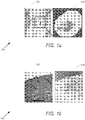
- FIG. 1a An optical and a terahertz based images of a tissue with Basal Cell Carcinoma in accordance with an embodiment of the invention is shown in FIG. 1a .
- the images 100 show an optical based image 102 side-by-side with a terahertz based image 104.
- optical and terahertz based images of a skin tissue with third-degree burn in accordance with an embodiment of the invention is shown in FIG. 1b .
- the images 150 show an optical based image 152 side-by-side with a terahertz based image 154. In both FIGS.
- the images generated utilizing terahertz based imaging show stronger contrasts for the cancerous and damaged tissue, respectively.
- specific images illustrating superior image contrasts using terahertz based imaging systems are discussed above with respect to FIGS. 1a-b , any of a variety of images and terahertz based imaging systems as appropriate to the requirements of a specific application can be utilized in accordance with embodiments of the invention.
- Systems and methods for terahertz endoscopy utilizing terahertz sources and detectors in accordance with embodiments of the invention are discussed further below.
- non-contact three-dimensional terahertz imaging can leverage the availability of femtosecond optical lasers that can generate sub-picosecond (10 12 second) electromagnetic pulses through photoconduction or nonlinear optical processes.
- FIG. 2a A schematic diagram illustrating a pulsed terahertz imaging system in reflection mode is shown in FIG. 2a .
- the pulsed terahertz imaging system 200 can be more compatible with medical imaging applications compared to various comparable imaging systems in transmission mode.
- the pulsed terahertz imaging system illustrated in FIG. 2a can be based on photoconductive terahertz sources and detectors as further discussed below.
- nonlinear optical processes can also be used for terahertz pulse generation and/or detection.
- a femtosecond optical pulse train from a mode-locked laser 202 can be incident on a photoconductive terahertz source 203 to generate a sub-picosecond terahertz pulse train 204 (typically with frequency components within 0.1-4 THz), which can then be focused onto a specific spot on a sample under test 205.
- a terahertz signal is reflected from the test sample and can be detected utilizing a photoconductive terahertz detector 206 where the detector can be probed by a copy of the femtosecond optical pump pulse train 207.
- a controllable optical delay line 208 can allow for adjusting the time-delay between the pump and probe optical beams and, thus, the reflected signal from the sample can be measured in the time domain.
- depth profile of the specific scanned spot on the sample can be resolved by measuring the amplitude and timing of the reflected signal. By scanning the sub-picosecond terahertz pulse train across other spots on the sample under test in the lateral direction and resolving the depth profile of each scanned spot, a three-dimensional image of the sample can be resolved.
- lateral resolution of the resolved image can be limited by diffraction and, thus, is determined based upon the effective wavelength of the incident terahertz beam inside the imaged object and numerical aperture of the utilized lenses.
- the depth resolution of the resolved image can be determined based upon the pulse width of the incident terahertz pulses inside the imaged object, which can be estimated as ⁇ c. ⁇ t/(2 n ), where c is the speed of light, ⁇ t is the pulse width of the incident terahertz pulse on the object, and n is the effective refractive index of the object at terahertz frequencies.
- a depth resolution of less than 0.1 mm can be expected for the pulsed imaging system with sub-picosecond terahertz pulses for medical imaging applications.
- this depth resolution is much better than what can be offered by other terahertz imaging systems based on continuous-wave terahertz sources, which are limited by the bandwidth and frequency of high power continuous-wave terahertz sources.
- pulsed terahertz imaging systems can offer superior depth resolutions compared to other terahertz imaging systems, there can be a number of factors that can still limit the scope and potential use of the pulsed terahertz imaging systems for practical medical imaging applications.
- a first limitation concerns the detectable penetration depth of the incident terahertz beam (maximum depth of tissue that can be imaged) which can be limited by attenuation of the imaged sample and the signal-to-noise ratio of the terahertz imaging system. While the attenuation of various types of biological tissue are bound by their structure and water content, the output terahertz power of photoconductive terahertz sources and sensitivity of photoconductive terahertz detectors (or any other type of pulsed terahertz source and detector employed in an imaging system) can be key factors for setting the maximum detectable penetration depth of the imaging system.
- some of the major challenges in realizing terahertz imaging systems for various medical diagnostics applications can include the relatively low radiation power of existing terahertz radiation sources and low detection sensitivity of existing terahertz detectors that limit the maximum detectable depth of the imaging system.
- a second limitation concerns image acquisition time, which can be limited by the axial scan time of the depth profile of each specific spot of the sample under test as well as the lateral scan time of all the spots across the sample.
- the axial scan time of the depth profile of each specific spot of the sample can be limited by the mechanical delay lines 208 utilized in a pulsed imaging system as illustrated in FIG. 2a .
- the axial scan times can be significantly reduced by use of phase-modulated dual-laser-synchronized control technology. For example, Advantest America, Inc.
- the axial scan times can be significantly reduced by utilizing imaging systems with higher signal-to-noise ratio levels
- the main limitation for achieving fast image acquisition rates can be that the lateral scan time of all the spots across the sample under test is limited by the mechanical scanning processes used in pulsed terahertz imaging systems.
- the terahertz imaging system 250 can include a phase-modulated dual-laser-synchronized control femtosecond laser comprising a first femtosecond laser 252 and a second femtosecond laser 254 that can be utilized for pumping plasmonic photoconductive terahertz sources 256 and detectors 258 to significantly reduce the axial scan time.
- the terahertz imaging system can be compatible with commercially available endoscopes such as (but not limited to) those produced by Karl Storz Endoscopy Inc.
- the large area plasmonic photoconductive sources and detectors can be compatible with 700 - 1550 nm optical wavelengths (including but not limited to 800, 1000, or 1550 nm) at which low dispersion optical fibers are available for maintaining the pulse width of the femtosecond pump beams over a fiber length of several meters.
- 750 nm optical wavelengths including but not limited to 800, 1000, or 1550 nm
- any of a variety of optical wavelengths as appropriate to the specific application can be utilized in accordance with embodiments of the invention.
- pulsed terahertz imaging system utilizing femtosecond lasers are discussed above with respect to FIGS. 2a-b , any of a variety of pulsed terahertz imaging systems incorporating femtosecond lasers as appropriate to the requirements of a specific application can be utilized in accordance with embodiments of the invention. Imaging systems based on an array of large area plasmonic terahertz sources and detectors in accordance with embodiments of the invention are discussed further below.
- a pulsed terahertz imaging system based on an array of large area plasmonic photoconductive terahertz sources and detectors can enable non-contact three dimensional imaging with significantly larger detectable depth and faster acquisition rates.
- the pulsed terahertz imaging system can be based on a two-dimensional array of large area plasmonic photoconductive terahertz sources and detectors compatible with commercially available endoscopes.
- the large area plasmonic photoconductive sources and detectors can be effective in enhancing the output power of terahertz sources, detection sensitivity of terahertz detectors and thus, signal-to-noise ratio of the imaging system by several orders of magnitude, enabling significantly larger detectable depths for the imaging system.
- the two-dimensional array of plasmonic photoconductive sources and detectors can significantly increase the image acquisition rate by reducing the lateral scan time.
- an image processing technique can be utilized to offer in-vivo terahertz imaging with large field of view.
- an image processing technique can be utilized that processes the image data from the terahertz imager with relatively small number of pixels together with the higher resolution optical images captured by an optical camera (available at the tip of the endoscope) while moving the endoscope tip.
- panoramic images can be produced from the optical and terahertz image data using cross registration algorithms to map the high resolution optical images to the terahertz images, which could be very beneficial for diagnostics purposes.
- the terahertz imaging systems can be expected to offer more than 3 mm detectable depth in biological tissue (can penetrate deeper depending on the tissue type) with depth resolution of ⁇ 30 um, sub-millimeter lateral resolution and image acquisition time of ⁇ 1 msec for each 3x3 pixels.
- Such a system could have a transformative impact on the scope and potential use of terahertz imaging for a variety of tomography and hydration/inflammation measurements with potential application including (but not limited to) the upper and lower gastrointestinal and respiratory tract.
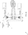
- FIG. 3 A schematic diagram of a terahertz imaging system utilizing an array of large area plasmonic terahertz sources and detectors in accordance with an embodiment of the invention is illustrated in FIG. 3 .
- the imaging system 300 can comprise a terahertz imager 301 comprising an array of large area plasmonic terahertz sources 302 and detectors 304 fabricated on an ErAs:InGaAs substrate 306, mounted on a silicon lens 308, and pumped by femtosecond optical beams from a phase-modulated dual-laser-synchronized control femtosecond laser ( ⁇ ⁇ 1550 nm).
- any of a variety of wavelengths as appropriate to the requirements of a specific application can be utilized in accordance with embodiments of the invention.
- the 1550 nm wavelength is selected since the Advantest phase-modulated dual-femtosecond-laser system operates at 1550 nm wavelength range and the availability of a large number of fiber optics components for coupling laser light to the arrays of terahertz sources and detectors.
- an array of polarization that maintains fiber splitters can be utilized to couple the dual laser beam into a polarization maintaining fiber bundle 310, that can be used to couple the pump and probe beams to the active area of large area plasmonic photoconductive terahertz source and detectors arrays, respectively.
- the arrays of terahertz sources and detectors can be arranged such that each terahertz detector is surrounded by four terahertz sources symmetrically.
- arrays of terahertz sources and detectors, optical pump/probe fiber bundle 314, electrical input to the terahertz source arrays 312 (bias voltage of the large area plasmonic terahertz sources), and electrical output of the terahertz detector arrays 312 (output current of the large area plasmonic terahertz detectors) can be arranged and packaged to fit inside a channel of various endoscopes 316 including (but not limited to) a commercially available endoscope that can vary in size and offer an empty channel including (but not limited to) channels with a diameter varying between 2 mm to 5 mm.
- the output of the terahertz detector can be an output current and/or an output voltage.
- the endoscopes can have flexibility allowing ⁇ 100 degree tilting at the tip, making it possible to capture images from the gastrointestinal and respiratory tract side walls from various angles.
- the imaging systems can include an optical light source 318 and an optical camera 320 such as (but not limited to) a fiber bundle or CCD imager placed at the tip of the endoscope having an optical camera output 322.
- images can be captured using the endoscope's optical camera 320 and the terahertz imager 301 (i.e. terahertz sources and detectors) simultaneously.
- capturing an image with the endoscope's optical camera and the terahertz imager simultaneously can improve image processing at various processing stages and for cross registering the optical and terahertz images for diagnostics applications.
- specific terahertz imaging systems using an array of large area plasmonic terahertz sources and detectors are discussed above with respect to FIG. 3
- any of a variety of terahertz imaging systems having an array of large area plasmonic terahertz sources and detectors as appropriate to the requirements of a specific application can be utilized in accordance with embodiments of the invention.
- Array of terahertz sources and detectors for terahertz imaging systems in accordance with embodiments of the invention are discussed further below.
- terahertz imaging systems in accordance with embodiments of the invention can include arrays of plasmonic photoconductive terahertz sources and detectors.
- a large area photoconductive source when the active area of a large area photoconductive source is illuminated by an optical pump beam, photo-generated electrons and holes are accelerated in opposite directions by the external bias electric field. The acceleration and separation of photo-carriers can induce a time-varying dipole moment within the device's active area which generates terahertz radiation.
- photo-generated electrons and holes can be accelerated in opposite directions by the incident terahertz field.
- the acceleration and separation of photo-carriers can induce a photocurrent within a device's active area proportional to the received terahertz field.
- Large area photoconductive sources and detectors can be suitable for the terahertz imaging system because they can offer very broad radiation bandwidth, which allows generation and detection of terahertz pulses with very narrow pulse widths, offering images with high depth resolution. Further, large area photoconductive sources and detectors can operate at higher optical pump power levels and, thus, offer higher radiation powers and higher detection sensitivities compared to other types of photoconductive terahertz sources and detectors, which can be limited by the carrier screening effect and thermal breakdown at higher optical pump powers. In addition, large area photoconductive sources and detectors typically do not need a very sensitive optical alignment due to their relatively large active areas, and thus simplifying alignment of large arrays of terahertz sources and detectors with a fiber bundle.
- Plasmonic contact electrodes can be utilized. Plasmonic contact electrodes can be effective in enhancing the radiation power and detection sensitivity of various photoconductive terahertz sources and detectors by reducing the transport path length of the photocarriers to the device contact electrodes.
- FIG. 4 A schematic diagram of a large area plasmonic photoconductive source and detector and its operation concept as a terahertz source in accordance with an embodiment of the invention is illustrated in FIG. 4 .
- the large area plasmonic photoconductive source and detector 400 incorporates plasmonic contact electrodes within the active area of large area photoconductive sources, most of the photocarriers are generated in close proximity to the contact electrodes. Therefore, the majority of the photocarriers that are drifted to the contact electrodes within a sub-picosecond time-scale. Since the contact electrodes accommodate photocurrent propagation velocities much higher than that of semiconductor substrate, a much stronger time-varying dipole moment can be induced in response to an incident optical pump 402 and, thus, greatly enhanced terahertz radiation power 404 can be achieved compared to conventional large area photoconductive sources.
- incorporating plasmonic contact electrodes within the active area of large area photoconductive detectors can increase the number of the photocarriers that are drifted to the contact electrodes within a sub-picosecond time-scale in response to an incident terahertz beam. Therefore, greatly enhanced terahertz detection sensitivity can be achieved compared to conventional large area photoconductive detectors.
- the device can be fabricated on an ErAs:InGaAs substrate 406, which is used for operation at ⁇ 1550 nm optical pump wavelengths.
- ErAs:InGaAs substrate can offer a short carrier lifetime for suppressing the low-frequency photocurrent and the relatively large substrate resistivity for maintaining a high bias electric field across the device active area and low noise operation.
- the ErAs:InGaAs substrate can offer a carrier lifetime of 0.85 ps and substrate resistivity of ⁇ 1 K ⁇ .cm.
- the device's active area can be comprised to include a set of interdigitated bias lines.
- arrays of plasmonic contact electrode gratings can be connected to anode bias lines of the photoconductive source within every other gap between the anode and cathode bias lines.
- the other gaps between the anode and cathode bias lines can be shadowed by a second metal layer deposited on top of a Si 3 N 4 antireflection coating 408 to block light transmission into the substrate and induce unidirectional dipole moment in the substrate.
- the geometry of the plasmonic contact electrode gratings and thickness of the Si 3 N 4 antireflection coating can be chosen to transmit the majority of the incident optical pump photons through the plasmonic gratings into the ErAs:InGaAs substrate.
- L p , g a , g c , W e can impact the performance of large area plasmonic photoconductive terahertz sources and detectors.
- the length of the plasmonic gratings, L p 410 should be selected much shorter than the effective terahertz radiation wavelength to achieve a broad terahertz generation/detection bandwidth and relatively large electric field along the entire grating length for efficient drift of the photocarriers to the plasmonic gratings.
- reducing the length of the plasmonic gratings, L p 410 can reduce the percentage of the device's active area in comparison with the shadowed area and, thus, can reduce the device's quantum efficiency.
- the gaps between the anode and cathode contact electrodes, g a 412 and g c 4 14 should be selected large enough to prevent electrical breakdown when applying bias voltages for efficient drift of photocarriers along the entire grating length.
- increasing the cathode contact electrodes, g a 412 and g c 414 can reduce the percentage of the device's active area in comparison with the shadowed area and, thus, can reduce the device's quantum efficiency.
- the width of the bias electrodes, W e , 416 should be large enough to accommodate the induced photocurrent during device operation (especially during operation as a terahertz source, when the induced photocurrent can be considerable).
- increasing the bias electrodes, W e , 416 can reduce the percentage of the device active area in comparison with the shadowed area and, thus, can reduce the device's quantum efficiency.
- the geometric parameters ( L p , g a , g c , W e ) can determine the overall device resistance, which can directly impact the noise floor of the radiated terahertz beam and detected terahertz signal.
- the impact of each geometric parameter can be readily investigated by one of ordinary skill in the art and optimum device geometry as appropriate to the requirements of a specific application of large area plasmonic photoconductive sources and detectors can be determined and utilized in accordance with embodiments of the invention.
- a finite-element solver can be used to design the plasmonic contact electrode gratings.
- a grating design for a large area plasmonic photoconductive sources and detectors along with a graph illustrating power transmission of a transverse-magnetic (TM) polarized optical beam in accordance with an embodiment of the invention is illustrated in Figure 5 .
- the graph 501 illustrates power transmission of a TM polarized optical beam as a function of wavelength.
- the grating design includes sources and detectors that can comprise Au gratings 502 with a 200 nm pitch, 100 nm metal width, and 50 nm metal height and a 250 nm thick Si 3 N 4 antireflection coating 504, offering 90% optical transmission into the ErAs:InGaAs substrate 506 at 1550 nm pump wavelength. Since transmission of the incident optical pump into the substrate is through excitation of surface plasmon waves and through 100 nm gaps between the plasmonic grating fingers, a large portion of the photocarriers are generated in close proximity to the plasmonic gratings.
- the photocurrent propagation velocity along plasmonic gratings is not limited by the carrier scattering inside the semiconductor substrate lattice. Therefore, the Hertzian dipole antennas formed by the plasmonic gratings can offer significantly higher radiation resistance and better impedance matching to free space compared with the radiating dipole induced within the semiconductor substrate of conventional large area photoconductive sources. Similarly, the use of plasmonic contact electrodes within the active area of large area photoconductive detectors can increase the induced ultrafast photocurrent in response to an incident terahertz radiation significantly. Therefore, greatly enhanced terahertz detection sensitivity can be achieved compared to typical large area photoconductive detectors.
- designs for the large area plasmonic photoconductive sources should maximize the optical-to-terahertz conversion efficiency and radiation power as well as the terahertz radiation bandwidth and the designs for the large area plasmonic photoconductive detectors should maximize the detection sensitivity and the terahertz detection bandwidth.
- high-aspect ratio plasmonic contact electrode gratings can be utilized for plasmonic contact electrodes in accordance with embodiments of the invention.
- the use of high-aspect ratio plasmonic electrodes can enhance the number of the photocarriers in close proximity to the plasmonic contact electrodes further and, thus, can offer higher terahertz radiation power levels and detection sensitivities for large area plasmonic photoconductive sources and detectors.
- a pulsed terahertz radiation power levels from a 1 ⁇ 1 mm 2 large area plasmonic photoconductive terahertz source operating at 800 nm optical pump wavelength range has been achieved using device concepts similar to the design for the terahertz imaging system as illustrated in FIG. 4 .
- the device can be fabricated on a semi-insulating (SI) GaAs substrate and the geometry of the plasmonic contact electrode gratings optimized for operation at 800 nm optical wavelengths.
- the fabrication process can start with patterning the plasmonic contact electrodes using electron-beam lithography, followed by 5/45 nm Ti/Au deposition and liftoff.
- An optical lithography step with a bi-layer photoresist can be used to pattern the bias lines, which can be followed by 50/550 nm Ti/Au deposition and liftoff.
- a Si 3 N 4 anti-reflection coating can be deposited using plasma-enhanced chemical vapor deposition (PECVD).
- PECVD plasma-enhanced chemical vapor deposition
- the shadow metal is patterned next through optical lithography, followed by 10/90 nm Ti/Au deposition and liftoff.
- the contact bias can be patterned using optical lithography and opened by etching the Si 3 N 4 layer using reactive ion etching (RIE).
- RIE reactive ion etching
- the device can be placed on a silicon lens and an optical rotation mount to adjust the polarization of the optical pump with respect to the plasmonic gratings.
- the plasmonic photoconductive source prototype 600 can include a 5 ⁇ m plasmonic grating length 602 and the plasmonic contact electrode gratings incorporated inside the device active area.
- Terahertz radiation from the fabricated large area plasmonic photoconductive source can be characterized in response to an optical pump beam from a Ti:sapphire mode-locked laser at 800 nm wavelength, with a repetition rate of 76 MHz and a pulse width of 200 fs.
- Spot size of the optical pump beam can be adjusted to illuminate the entire device active area and polarization of the optical pump beam can be set to be normal to the plasmonic contact electrode gratings.
- a calibrated pyroelectric detector such as (but not limited to) a Spectrum Detector, Inc. SPI-A-65 THz can be used to measure radiated power as a function of the bias voltage and optical pump power.
- a record-high terahertz radiation power of 3.6 mW can be detected at an optical pump power of 150 mW, exhibiting two orders of magnitude higher optical-to-terahertz conversion efficiencies compared to conventional large area photoconductive terahertz sources.
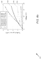
- FIG. 6b A graph illustrating radiated power from a plasmonic photoconductive source in accordance with an embodiment of the invention is shown in Fig. 6b .
- the graph 650 illustrates the radiated terahertz power in mW as a function of voltage.
- the line 652 corresponds to a pump power of 30 mW
- line 656 corresponds to a pump power of 60 mW
- lines 654 corresponds to a pump power of 90 mW
- line 658 corresponds to a pump power of 150 mW.
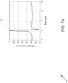
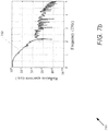
- the radiated electric field from the fabricated large area plasmonic photoconductive source can be characterized in a time-domain terahertz spectroscopy setup with electro-optic detection in a 1 mm thick ZnTe crystal. Measured time-domain radiated field and frequency-domain radiated power in accordance with an embodiment of the invention are shown in FIG. 7a and FIG. 7b , respectively.
- Graph 700 illustrates a time-domain radiated field of a large area plasmonic photoconductive source at 50 mW optical pump power.
- the radiated field 702 exhibits a terahertz radiation pulse width of 0.5 ps full width at half maximum (FWHM).
- Graph 750 illustrates a frequency-domain radiated power of a large area plasmonic photoconductive source at 50 mW optical pump power.
- the radiated power 752 shows a terahertz radiation spectrum in the 0.1-5 THz frequency range with more than 100 dB signal to noise ratio.
- the geometry of the large area plasmonic photoconductor for an array of terahertz sources and detectors fabricated on an ErAs:InGaAs substrate can be optimized with the highest terahertz radiation power and detection sensitivity, respectively, while maintaining a broad terahertz radiation/detection bandwidth.
- Use of ErAs:InGaAs substrates can allow operation at 1550 nm optical pump/probe wavelengths offered by the Advantest phase-modulated dual-femtosecond-laser system.
- the short carrier lifetimes offered by the ErAs:InGaAs substrates can offer relatively lower noise floors for the large area plasmonic photoconductive terahertz sources and detectors, compared to other photoabsorbing substrates at 1550 nm wavelengths, by reducing the induced low frequency photocurrent.
- an array of 4x4 large area plasmonic photoconductive sources and an array of 3x3 large area plasmonic photoconductive detectors such that each terahertz detector is surrounded by four terahertz sources symmetrically can be utilized as illustrated in FIG. 3 . Further, an area of 250x250 ⁇ m 2 can be selected for each source and detector.
- the ErAs:InGaAs substrate can be mounted on a silicon lens with ⁇ 5 mm diameter, while centering the terahertz source/detector arrays in the center of the lens to have a radiation uniformity across the entire array.
- the device can be mounted on a motorized XYZ translation stage and the optical alignment can be optimized iteratively using computer control and by maximizing the device photocurrent under an optical illumination. After reaching the optimum alignment, a UV-curable epoxy can be used to fix the position of the fiber bundle relative to the device.
- the available optical pump/probe power from the Advantest phase-modulated dual-femtosecond-laser system and experimental results signal-to-noise ratio of at least 80 dB for each large area plasmonic photoconductive detector in the 3x3 array should be achievable.
- this can offer more than 3 mm detectable depth in biological tissue. It should be noted that the terahertz absorption and penetration depth varies for different types of biological tissue based on their structure and water content. Therefore, much deeper detectable depths are expected when using the proposed terahertz imaging system in the respiratory tract compared with gastrointestinal tract.
- the expected radiation/detection bandwidth of the large area plasmonic photoconductive sources and detector is expected to accommodate resolving terahertz pulses with at least 0.5 ps pulse width, offering a depth resolution of less than ⁇ 30 um for the proposed terahertz imaging system.
- a lateral resolution of ⁇ 0.5 mm can be expected for terahertz imaging systems in accordance with embodiments of the invention, which can be limited by the physical size of the large area plasmonic photoconductive detectors, numerical aperture of the silicon lens, and the diffraction limit.
- design considerations can be estimated by assuming one axial scan for each pixel, which offers an image acquisition time of ⁇ 1 msec for the 3x3 pixels when using the Advantest phase-modulated dual-femtosecond-laser system. It should be noted that the signal-to-noise ratio of the terahertz imaging system can be improved by increasing the number of the axial scans and averaging the captured data. This offers an imaging system with higher signal-to-noise ratio levels and, thus, deeper penetration depths at the expense of reducing the image acquisition rate.
- terahertz imaging systems in accordance with embodiments of the invention could have a transformative impact on the scope and potential use of terahertz imaging for a variety of tomography and hydration/inflammation measurements with potential application in the upper and lower gastrointestinal and respiratory tract.
- a deconvolution technique can be utilized to resolve the depth profile of each pixel from the temporal waveform of the reflected terahertz beam from each pixel.
- an array of terahertz sources as discussed above can be utilized to illuminate the surface of a flat gold mirror with terahertz pulses and record the reflected terahertz waveform at each pixel as a reference signal x(t).
- a window function e.g. the Gaussian function
- the Gaussian function may be utilized to prevent error in the resolved image profile at the expense of losing high frequency data.
- the total number of image pixels could be limited in many embodiments of the terahertz imaging system (i.e. 3 ⁇ 3).
- systems with larger number of pixels can be explored and image processing techniques that would offer a larger field of view while using the 3x3 pixel array can also be considered.
- image data from the terahertz imager can be processed with small number of pixels together with the higher resolution optical images captured by the optical camera (available at the tip of the endoscope) while moving the endoscope tip.
- existing photography software packages can be used to overlap and stitch the captured optical and terahertz images and produce panoramic optical and terahertz images.
- image cross registration algorithms can be utilized to map the high resolution optical images to the resolved terahertz images.
- terahertz imaging systems in accordance with embodiments of the invention can be tested on various low-loss multi-layered samples (e.g. stacks of paper, plastic, and paint) to characterize its signal-to-noise ratio and depth resolution. Such tests can assist in troubleshooting the developed image processing/reconstruction algorithms and procedures.
- the terahertz imaging systems can be mounted on a flexible endoscope for imaging inside the respiratory and digestion tract of a carcass such as (but not limited to) that of a cow. It should be noted that phantoms specific to various biological tissues can be unavailable for the terahertz frequency range, and thus the most realistic samples to begin with could be organs from dead animals (e.g. cow lung and stomach). In this regard, the potential use of such high-performance terahertz imaging systems in accordance with embodiments of the invention can be explored on animal and human subjects. Some additional technical considerations and possible solutions are illustrated in Table I below.
- Lung cancer is the deadliest cancer in North America and most of the developed world with an overall 5-year survival rate of less than 30% for different cancer stages.
- Terahertz bronchoscopy systems in accordance with embodiments of the invention can be utilized for early-stage lung cancer diagnosis and screening.
- Such systems can utilize plasmonic pulsed terahertz imaging techniques as described above and be compatible with minimally invasive, flexible bronchoscopy probes and advanced navigation modalities to offer real-time 3D tomographic images of airways, pulmonary nodules, and lung structure.
- terahertz bronchoscopy systems can offer a depth resolution of ⁇ 50 um and a sub-millimeter lateral resolution revealing structural and shape information of much deeper peripheral nodules that cannot be detected by optical coherence tomography (OCT) and confocal microscopy (CFM). Further, terahertz bronchoscopy systems in accordance with embodiments of the invention could impact next generation pulmonary imaging toolset, enabling early-stage detection of lung cancer by providing more detailed information about the shape, size, physical and molecular structure of pulmonary nodules that cannot be scanned by OCT, CFM, and endobronchial ultrasound (EBUS), thus improving the likelihood ratio of targeting cancerous nodules in biopsy and surgery and improving therapy strategies.
- OCT optical coherence tomography
- CFM confocal microscopy
- terahertz waves do not pose an ionization hazard for human tissue due to their very low energy compared to shorter wavelength waves especially X-rays. Additionally, terahertz waves experience less scattering from biological tissue compared to optical waves due to their longer wavelengths, making it possible to see deeper into different biological tissue types. Moreover, several absorption lines of water and oxygen lie in the terahertz frequency spectrum, making terahertz waves very powerful means for distinguishing between tissues with different molecular/physical structure, hydration level, and hypoxia level, which are major sources of contrast between different tissue types (e.g. normal and malignant nodules). Another unique attribute of terahertz waves is their capability to identify molecules and biomarkers specific to special types of cancer, which can be an advantage in increasing the likelihood ratio of identifying cancerous nodules for improved therapy/biopsy/surgery strategies.
- pulsed terahertz imaging with asynchronous optical sampling may be an appropriate scheme for resolving tissue images with high depth/thickness resolution and high image acquisition speeds.
- a schematic diagram of an ASOPS pulsed terahertz imaging system in reflection mode in accordance with an embodiment of the invention is shown in FIG. 8 .
- the imaging system 800 includes two offset-locked femtosecond lasers 802 with different repetition rates 804 and 806 that pump/probe a photoconductive terahertz source 808 and/or detector 810 to generate 809 and/or detect 811 sub-picosecond terahertz pulses, respectively.
- the imaging process starts when the femtosecond optical pump pulse train from the pump mode-locked laser is incident on a photoconductive terahertz source 808 to generate a sub-picosecond terahertz pulse train, which is then focused 812 onto a specific spot on the imaged tissue 814.
- the reflected terahertz pulse 816 from the imaged tissue 814 which includes reflected echo pulses from different tissue layers, is then detected by use of a photoconductive terahertz detector 810 probed by the femtosecond optical probe pulse train from the probe mode-locked laser.
- the difference between the repetition rates of the optical pump and probe pulses allows adjusting the time-delay between the pump and probe optical beams and, thus, measuring the reflected signal from the imaged tissue in the time domain.
- Depth profile of the specific scanned spot on the imaged tissue is resolved by measuring the amplitude and timing of the reflected pulses.
- a 3D image of the tissue is resolved.
- an ASOPS imaging modality combined with existing dual offset-locked femtosecond lasers allows resolving the depth profile of each image pixel in less than a 1 ms
- the image acquisition time of existing terahertz imaging systems is still limited by the mechanical scanning process used in existing terahertz imaging systems.
- the image depths offered by existing terahertz imaging systems are limited by low power levels and low sensitivity levels of available terahertz sources and detectors.
- terahertz imaging techniques and devices for incorporation into bronchoscopy systems are discussed above with respect to FIG. 8 , any of a variety of terahertz imaging systems as appropriate to the requirements of a specific application can be utilized in accordance with embodiments of the invention. Additional processes and devices for terahertz bronchoscopy systems in accordance with embodiments of the invention are discussed further below.
- a terahertz imaging modality based on plasmonic terahertz source/detector technology can be utilized to enhance the image depth and image acquisition time of existing terahertz imaging systems through a minimally-invasive, flexible bronchoscopy platform that can be used for but not limited to in vivo lung screening.
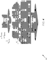
- imaging system 900 can be utilized for resolving real-time, 3D images of lung tissue with more than 1 cm image depth, submillimeter lateral resolution and 50 um depth resolution. It is specifically designed to fit inside a narrow-diameter, flexible OCT-style catheter, compatible with the working channel of standard bronchoscopes for airway imaging.
- a key enabler of the imaging system can be a plasmonic terahertz source and detector 902 fabricated side by side on an ErAs:InGaAs substrate (as illustrated in Fig. 9b ), mounted on a silicon lens 904.
- the plasmonic terahertz source and detector can be designed to operate at 1550 nm optical wavelengths to be compatible with low-dispersion fiber-coupled systems.
- the plasmonic terahertz source and detector can be designed to produce 0.6 ps terahertz pulses with more than 3 mW power levels incident on the scanned tissue 906 and an overall signal-to-noise ratio of 100 dB for the detected pulses, which can offer more than 1 cm image depth and 50 um depth resolution.
- Two low-dispersion optical fibers connected to an external 1550 nm dual femtosecond laser system, carrying the pump and probe femtosecond pulses, can be packaged with the devices such that the pump and probe beams illuminate the active area of the plasmonic terahertz sources and detectors, respectively.
- the silicon lens 904, pump/probe fiber connectors 908 and the electrical input/output connectors 910 of the plasmonic sources and detectors can be mounted on a metallic protective holder 912 inside the catheter.
- the radiated terahertz pulses can be focused onto the scanned tissue 906 through the silicon lens 904 and a polyethylene lens 914 mounted on the metallic protective holder.
- a rotating gold mirror 916 can be used to scan the normally-incident terahertz pulses on the lung tissue across the bronchial wall.
- the mirror can be mounted at a 45° angle on a micromotor 918, which can be mounted on the metallic protective holder inside the catheter.
- the reflected terahertz pulses from the tissue are reflected from the same gold mirror and focused onto the plasmonic terahertz detector 902 through the polyethylene 914 and silicon lenses 904.
- the metallic protective holder can be used to fix the micromotor 918 to a torque coil 920.
- a FEP plastic sheath 922 can cover the metallic protective holder and micromotor 918.
- the terahertz imaging system can include plasmonic terahertz source and detector, which can be designed to have an active area of 0.5 ⁇ 0.5 mm 2 .
- a schematic diagram and operation concept of a plasmonic terahertz source/detector in accordance with an embodiment of the invention is illustrated in FIG. 9b .
- the plasmonic terahertz source/detector 950 can include an active area 952 utilizing a ErAs:InGaAs substrate 953.
- photo-generated electrons 956 and holes 958 are accelerated in opposite directions by an external bias electric field.
- the acceleration and separation of the photocarriers induce a time-varying dipole moment within the device active area which generates terahertz radiation 960.
- the active area of the plasmonic detector is illuminated by an optical probe beam 954, photo-generated electrons 956 and holes 958 are accelerated in opposite directions by the received terahertz field 960 reflected from the imaged tissue.
- the acceleration and separation of the photocarriers induce a photocurrent within the device active area which is proportional to the received terahertz field.
- the plasmonic terahertz source/detector design uses plasmonic contact electrodes 962 inside the device active area that concentrates the majority of the photocarriers in close proximity to the device contact electrodes to efficiently contribute to terahertz generation and detection. This can result in significantly higher terahertz radiation powers and detection sensitivities compared to conventional designs. In many embodiments, the such configurations have demonstrated more than two orders of magnitude terahertz power enhancement and more than one order of magnitude terahertz detection sensitivity enhancement by use of plasmonic contact electrodes.
- the design and geometry of the plasmonic device for a plasmonic terahertz source and detector fabricated on an ErAs:InGaAs substrate should be considered.
- Use of ErAs:InGaAs allows operation at 1550 nm optical pump/probe wavelengths at which low-dispersion fibers, fiber components, and fiber lasers are available. This allows maintaining short optical pump/probe widths and, therefore, short terahertz pulse widths in order to obtain 3D terahertz images with a high depth resolution.
- short carrier lifetime of ErAs:InGaAs offers relatively lower noise floors for the plasmonic terahertz sources and detectors, compared to other photoabsorbing substrates at 1550 nm wavelengths, by reducing the induced low frequency photocurrent.
- the performance of a variety of plasmonic terahertz source/detector geometries and architectures to study the tradeoffs between terahertz radiation power and detection sensitivity relative to the terahertz radiation/detection bandwidth for each design can be investigated to determine designs with highest terahertz radiation power levels, detection sensitivity levels, and terahertz generation/detection bandwidths to maximize the imaging depth, image contrast (signal-to-noise ratio), and image resolution.
- image contrast and image depth may degrade with polarization variability of the optical pump/probe pulses due to fiber bending/stretching effects.
- plasmonic contact electrodes utilized in the plasmonic terahertz sources and detectors can polarization sensitive, variations in optical pump/probe polarization can degrade terahertz radiation power and detection sensitivity levels.
- plasmonic contact electrode structures with symmetric geometries e.g. periodic nanoscale cross-shapes and ring-shape structures rather than nanoscale gratings, which would exhibit polarization-independent optical absorption/enhancement should be considered.
- terahertz bronchoscopy systems are discussed above with respect to FIGS. 9a-b , any of a variety of terahertz bronchoscopy systems utilizing plasmonic terahertz sources and detectors as appropriate to the requirements of a specific application can be utilized in accordance with embodiments of the invention. Terahertz bronchoscopy design considerations and performance in accordance with embodiments of the invention are discussed further below.
- 0.6 ps terahertz pulses with 50 MHz repetition rate and more than 3 mW power levels with 100 dB signal-to-noise ratio levels can be achieved by use of the proposed plasmonic terahertz sources/detectors pumped/probed by the dual femtosecond laser system. Based on these specifications and measured characteristics of human lung tissue, predictions for the performance of the proposed terahertz bronchoscopy system can be made. As discussed above, the depth resolution of the resolved image can be determined by the pulse width of the incident terahertz pulses inside the imaged tissue, which is estimated as ⁇ c.
- ⁇ t/(2 n ) ⁇ t/(2 n )
- c the speed of light
- ⁇ t the pulse-width of the incident terahertz pulse on the tissue ( ⁇ t ⁇ 0.6 ps)
- n the effective refractive index of the tissue (2.2-1.8 in the 0.1-2 THz frequency range). Therefore, a depth resolution of ⁇ 50 um can be expected in several embodiments of the pulsed imaging system, which is much better than the depth resolution offered by CT.
- the image depth can be estimated as ⁇ 1.16 log ( SNR )/ ⁇ , where SNR is the signal-to-noise ratio of the imaging system, ⁇ is the linear absorption coefficient of the tissue (0.5-12 cm -1 in the 0.1-2 THz frequency range).
- SNR the signal-to-noise ratio of the imaging system
- ⁇ the linear absorption coefficient of the tissue (0.5-12 cm -1 in the 0.1-2 THz frequency range).
- the absorption spectra of different types of lung tissue samples over a broader terahertz frequency range can be measured and the results used for making more accurate predictions for the image depth of the system.
- the lateral resolution of the resolved image can be limited by diffraction and, thus, determined by the effective wavelength of the incident terahertz beam inside the imaged tissue and numerical aperture and aberration of the utilized lenses. Therefore, a sub-millimeter lateral image resolution can be estimated when imaging lung tissues, which is comparable with the lateral resolution of CT and EBUS images.
- axial scanning speeds as fast as 1 msec / scan can be offered by commercially available dual femtosecond laser that can be utilized in various embodiments.
- plasmonic terahertz sources and detectors can be fabricated on ErAs:InGaAs substrates because of their high optical absorption at 1550 nm optical wavelength and their short carrier lifetime levels required for generation/detection of very short terahertz pulses while suppressing background low-frequency photocurrent of the device for maintaining a low noise operation.
- the fabrication process begins with patterning the plasmonic contact electrodes using electron-beam lithography, followed by metal deposition and liftoff.
- An optical lithography step can be used to pattern the bias lines, which is followed by metal deposition and liftoff.
- a Si 3 N 4 anti-reflection coating can be deposited using plasma-enhanced chemical vapor deposition.
- a shadow metal layer can be patterned next through optical lithography, followed by metal deposition and liftoff.
- Contact vias can be patterned using optical lithography and opened by etching the Si 3 N 4 layer using reactive ion etching.
- the devices can be then mounted on a silicon lens and input/output electrical wires bonded to the contact vias.
- the silicon lens can be temporarily mounted on a rotation mount to connect the optical pump/probe fibers to the plasmonic terahertz source/detector.
- each fiber is typically placed inside a fiber holder on a XYZ translation stage and optical alignment is optimized iteratively for each fiber using computer control and by maximizing the device photocurrent under an optical illumination.
- a UV-curable epoxy can be used to fix the position of each fiber relative to the device.
- the terahertz power, terahertz pulse width, and signal-to-noise ratio of the imaging systems should be characterized before integrating the device with a suitable catheter.
- the radiated power can be measured by a calibrated pyroelectric detector.
- the silicon lens can be placed in front of a flat gold mirror to have the generated terahertz pulses normally incident on the mirror. The reflected terahertz beam can then be measured in the time domain and terahertz pulse width and signal-to-noise ratio of the imaging system is calculated accordingly.
- the optimum location of the polyethylene lens can be determined in this process by maximizing the signal-to-noise ratio of the imaging system.
- the process is repeated when adding the rotating mirror at 45 degrees angle changing the terahertz beam path by 90 degrees, compatible with the proposed system shown in FIG. 9a .
- the size and geometry of the lenses can be chosen such that the whole silicon lens/polyethylene lens/rotting mirror system fits in a 2-3 mm diameter catheter with a 1 cm length, while providing a sub-millimeter terahertz beam size within a 2 cm distance from the edge of the rotating mirror. Further, terahertz beam size at different distances can be measured by knife-edge technique.
- the performance of the imaging system can be characterized for resolving the depth profile of fresh human lung tissue samples.
- the temporal waveform of the reflected terahertz beam from each scanned spot can be captured through a lock-in amplifier in form of a digital data and continuously stored by use of a 64-bit computer with 32 GB memory, while scanning different spots on the tissue samples.
- signal processing can be performed using a deconvolution technique to resolve the depth profile of each imaged spot from the temporal waveform of the reflected terahertz beam from that spot.
- One challenge in resolving the depth profile can be various reflections in the imaging system, which might be falsely interpreted as reflections from tissue layers.
- signal processing techniques can be optimized before integrating the terahertz imaging system with the catheter and by use of a linear scan.
- the terahertz imaging system can be used to illuminate the surface of a flat gold mirror and record the reflected terahertz waveform as a reference signal x(t).
- a window function e.g. the Gaussian function
- a cross-sectional image profile of the lung tissue sample can be resolved and compared with tissue histology to assess the image depth, depth resolution, and contrast of the developed imaging system.
- the imaging system can be integrated with a catheter.
- Packaging the proposed terahertz imaging system within a 2-3 mm diameter, 1 cm long catheter can be a challenging task. Since the size and distance of the components are comparable with terahertz wavelengths, the performance of the proposed imaging system will be affected by spatial misalignments between components.
- the diameters of the silicon lens, polyethylene lens, rotating mirror, and micromotor can be set to match the diameter of a series of threads perforated inside a metallic protective holder at the optimum distanced determined in previous terahertz imaging characterization steps.
- the protective holder can be built from two complementary half tubes.
- the whole system can be put together by placing the silicon lens, polyethylene lens, rotating mirror, micromotor, and torque coil inside the first protective half-tube at the designated locations specified by the threads followed by the second protective half-tube covering the rest of the package.
- the gaps between the two metallic half tubes are filled with a UV-curable epoxy and the whole package is placed inside a FEP sheath.
- Terahertz bronchoscopy design implementation and considerations in accordance with embodiments of the invention are discussed further below.
- terahertz imaging system for bronchoscopy can be employed utilizing a flexible bronchoscope with a 2.8 mm diameter working channel.
- a testing apparatus comprising a metallic tube with a cut-through opening can be used to represent a bronchial channel as illustrated in FIG. 10 .
- the apparatus 1000 can include a metallic tube 1001.
- human lung tissue samples 1002 can be placed on a plastic sheath 1004 that can be configured to cover an opening 1006.
- the bronchoscope carrying the terahertz scanner can be inserted into the metallic tube 1001 to capture a 3D image of the lung tissue sample 1002 within the opening area 1006.
- the diameter of the catheter covering the terahertz imaging system can be set to be less than 2.8 mm to fit into the working channel of the bronchoscope 1008.
- the diameter of the metallic tube 1001 can be set to be slightly larger than the bronchoscope diameter.
- tissue samples can be extracted in surgery, which contain various types of malignant and non-malignant nodules. Since the imaging modality is in reflection mode, there is no specific requirement for the thickness of the tissue samples. This allows a fast sample preparation process and maintaining most of the tissue water content to achieve realistic terahertz images.
- the resolved terahertz images can be compared with tissue histology to evaluate contrast ratios of normal tissue and malignant/nonmalignant nodules as well as the image depth and lateral/depth resolution.
- a consideration in resolving 3D terahertz images can be etalon effects due to multiple reflections between the FEP sheath interfaces and the surface of the scanned tissue.
- the negative impact of these effects can be eliminated through the calibration process described in the signal processing section above.
- the calibration process can be sensitive to the spacing between the tissue and FEP sheath, which can be hard to maintain in realistic settings.
- the calibration process performed using a reflective gold mirror can be conducted for all possible distances between the FEP sheath and tissue surface (0.1-4 mm range) with a distance step size less than 50 um and the measured calibration data is recorded.
- the distance between the sheath and tissue surface can be estimated by measuring the time delay of the first echo pulse reflected from the surface of the tissue and the calibration data corresponding the measured distance is used for resolving terahertz images.
- tissue characterization Another consideration in the process of lung tissue characterization is maintaining tissue freshness, since the tissue water content would be a crucial factor in determining the terahertz signal penetration depth in the tissue and the image depth accordingly.
- tissue taping/sealing techniques to maintain tissue freshness over longer times should be considered, while planning a carefully organized coordination between various tissue transfer and measurement steps.
- sample freshness should not be ignored when assessing the performance of the developed terahertz bronchoscopy system for in vivo lung screening.
- other factors that will not be accounted for in an evaluation platform using replica models of a bronchial channel can include the motion artifacts secondary to cardiac pulsations and respiratory movements.
- terahertz bronchoscopy systems in accordance with embodiments of the invention should be evaluated for in vivo lung screening using animal/human subjects through various collaborative clinical/translational research projects.
Claims (20)
- Ein Terahertzabbildungssystem für Endoskopie, das Folgendes beinhaltet:
ein Terahertzbildgerät (301), das zum Empfangen von Terahertzbilddaten konfiguriert ist, das Folgendes beinhaltet:ein Faserbündel (310);mindestens eine Terahertzquelle (302), die zum Erzeugen von Terahertzstrahlung konfiguriert ist, wobei jede der mindestens einen Terahertzquelle (312) einen aktiven Bereich aufweist, der mindestens eine plasmonische Kontaktelektrode aufweist, die durch optische Sondenstrahlen erleuchtet werden kann, um die Terahertzstrahlung zu erzeugen; undmindestens einen Terahertzdetektor (304), der zum Empfangen von Terahertzfelddaten konfiguriert ist, wobei jeder des mindestens einen Terahertzdetektors einen aktiven Bereich aufweist, der mindestens eine plasmonische Kontaktelektrode (962) aufweist, die durch optische Pumpstrahlen (402) erleuchtet werden kann, um einen zu dem empfangenen Terahertzfeld proportionalen Ausgang zu induzieren;dadurch gekennzeichnet, dass die/der mindestens eine Terahertzquelle und -detektor in einer zweidimensionalen Anordnung angeordnet sind, sodass jeder Terahertzdetektor von einer Vielzahl von Terahertzquellen symmetrisch umgeben ist; undwobei das Faserbündel optische Pumpstrahlen mit dem aktiven Bereich der mindestens einen Terahertzquelle und optische Sondenstrahlen mit dem aktiven Bereich des mindestens einen Terahertzdetektors koppelt. - Terahertzabbildungssystem gemäß Anspruch 1, das ferner eine optische Lichtquelle (318) beinhaltet, die zum Erleuchten mindestens eines Ziels konfiguriert ist.
- Terahertzabbildungssystem gemäß Anspruch 2, das ferner eine optische Kamera (320) beinhaltet, die zum Empfangen von mit dem Erleuchtungsziel zusammenhängenden optischen Bilddaten konfiguriert ist.
- Terahertzabbildungssystem gemäß Anspruch 1, das ferner eine Laserquelle beinhaltet, die zum Pumpen der mindestens einen Terahertzquelle und zum Sondieren des mindestens einen Terahertzdetektors unter Verwendung von optischen Femtosekundenstrahlen konfiguriert ist.
- Terahertzabbildungssystem gemäß Anspruch 4, wobei die Laserquelle ein Femtosekundenlaser mit Phasenmodulations- und Duallasersynchronisationssteuerung
- Terahertzabbildungssystem gemäß Anspruch 1, wobei die/der mindestens eine Terahertzquelle und -detektor auf einem InGaAs-Substrat gefertigt sind.
- Terahertzabbildungssystem gemäß Anspruch 1, wobei die/der mindestens eine Terahertzquelle und -detektor auf einem GaAs-Substrat gefertigt sind.
- Terahertzabbildungssystem gemäß Anspruch 1, das ferner einen elektrischen Eingang in die mindestens eine Terahertzquelle beinhaltet, um eine Vorspannung zu erzeugen.
- Terahertzabbildungssystem gemäß Anspruch 1, das ferner einen elektrischen Ausgang aus dem mindestens einen Terahertzdetektor beinhaltet, der zum Sammeln des Ausgangs aus dem mindestens einen Terahertzdetektor konfiguriert ist.
- Terahertzabbildungssystem gemäß Anspruch 1, wobei die/der mindestens eine Terahertzquelle und -detektor auf einer Siliciumlinse (308) montiert sind.
- Terahertzabbildungssystem gemäß Anspruch 1, wobei die/der mindestens eine Terahertzquelle und -detektor in einer Anordnung angeordnet sind, sodass jeder Terahertzdetektor von vier Terahertzquellen symmetrisch umgeben ist.
- Terahertzabbildungssystem gemäß Anspruch 3, wobei Bilddaten gleichzeitig von der optischen Kamera und dem Terahertzbildgerät gesammelt werden.
- Terahertzabbildungssystem gemäß Anspruch 12, wobei mindestens ein Panoramabild aus den optischen Bilddaten und Terahertzbilddaten unter Verwendung von Kreuzregistrierungsalgorithmen zum Abbilden der optischen Bilddaten auf die Terahertzbilddaten erzeugt wird.
- Terahertzabbildungssystem gemäß Anspruch 13, wobei die/der mindestens eine Terahertzquelle und -detektor mit optischen Wellenlängen von 1550 Nanometern kompatibel sind.
- Terahertzabbildungssystem gemäß Anspruch 13, wobei die/der mindestens eine Terahertzquelle und -detektor mit mindestens einem von Folgendem kompatibel sind: optischen Wellenlängen von 800 Nanometern und optischen Wellenlängen von 1000 Nanometern.
- Terahertzabbildungssystem gemäß Anspruch 1, das ferner mindestens eine optische Linse beinhaltet.
- Terahertzabbildungssystem für Endoskopie gemäß Anspruch 1 und ferner beinhaltend mindestens ein rotierendes Element (916), das zum Reflektieren der erzeugten Terahertzstrahlung über abgetastetes Material konfiguriert ist; und
wobei die mindestens eine Terahertzquelle, das mindestens eine rotierende Element und der mindestens eine Terahertzdetektor in einem Katheter angeordnet sind. - Terahertzabbildungssystem gemäß Anspruch 17, wobei das mindestens eine rotierende Element ein in einem bestimmten Winkel auf einem Mikromotor innerhalb des Katheters montierter Spiegel ist.
- Terahertzabbildungssystem gemäß Anspruch 18, wobei der Mikromotor das mindestens eine rotierende Element während der Reflektion der erzeugten Terahertzstrahlung über das abgetastete Material rotieren kann.
- Terahertzabbildungssystem gemäß Anspruch 17, wobei:die mindestens eine Terahertzquelle mindestens eine plasmonische Kontaktelektrode aufweist; undder mindestens eine Terahertzdetektor mindestens eine plasmonische Kontaktelektrode aufweist.
Applications Claiming Priority (2)
| Application Number | Priority Date | Filing Date | Title |
|---|---|---|---|
| US201562167201P | 2015-05-27 | 2015-05-27 | |
| PCT/US2016/034704 WO2016196309A2 (en) | 2015-05-27 | 2016-05-27 | Terahertz endoscopy through laser-driven terahertz sources and detectors |
Publications (3)
| Publication Number | Publication Date |
|---|---|
| EP3302224A2 EP3302224A2 (de) | 2018-04-11 |
| EP3302224A4 EP3302224A4 (de) | 2019-02-27 |
| EP3302224B1 true EP3302224B1 (de) | 2020-10-14 |
Family
ID=57441706
Family Applications (1)
| Application Number | Title | Priority Date | Filing Date |
|---|---|---|---|
| EP16804130.9A Active EP3302224B1 (de) | 2015-05-27 | 2016-05-27 | Terahertzendoskopie durch laserbetriebene terahertzquellen und -detektoren |
Country Status (4)
| Country | Link |
|---|---|
| US (1) | US10863895B2 (de) |
| EP (1) | EP3302224B1 (de) |
| JP (1) | JP6860210B2 (de) |
| WO (1) | WO2016196309A2 (de) |
Families Citing this family (17)
| Publication number | Priority date | Publication date | Assignee | Title |
|---|---|---|---|---|
| WO2013112608A1 (en) | 2012-01-23 | 2013-08-01 | The Regents Of The University Of Michigan | Photoconductive device with plasmonic electrodes |
| JP6860210B2 (ja) | 2015-05-27 | 2021-04-14 | ザ リージェンツ オブ ザ ユニバーシティ オブ カリフォルニアThe Regents Of The University Of California | レーザ駆動式テラヘルツ源および検出器を通したテラヘルツ内視鏡検査 |
| FR3077641B1 (fr) * | 2018-02-07 | 2020-02-21 | TiHive | Systeme d'imagerie terahertz a reflexion |
| US10571393B2 (en) * | 2018-04-13 | 2020-02-25 | Tsinghua University | Terahertz gas detection method and device based on Gregory double reflection antenna |
| CN108898132B (zh) * | 2018-05-25 | 2022-08-12 | 广东工业大学 | 一种基于形状上下文描述的太赫兹图像危险品识别方法 |
| CN110448806B (zh) * | 2019-08-29 | 2022-02-22 | 鲍玉珍 | 太赫兹波理疗终端、用于早中期帕金森的太赫兹波理疗系统 |
| WO2021067635A1 (en) * | 2019-10-01 | 2021-04-08 | The Regents Of The University Of California | Method for identifying chemical and structural variations through terahertz time-domain spectroscopy |
| EP4052458A4 (de) * | 2019-10-31 | 2023-11-29 | The Regents of the University of California | Verfahren und systeme zur detektion des wasserstatus bei pflanzen mittels terahertzstrahlung |
| CN110864717B (zh) * | 2019-11-27 | 2021-11-05 | 上海明垒实业有限公司 | 太赫兹单元检测器旋转支架及检测装置 |
| KR102361898B1 (ko) * | 2020-02-13 | 2022-02-10 | 서울시립대학교 산학협력단 | 테라헤르츠 전자기파를 이용한 통풍 진단 장치 |
| US11460399B2 (en) * | 2020-04-13 | 2022-10-04 | University Of Central Florida Research Foundation, Inc. | Spectrally selective pyroelectric detection device and associated method of use |
| CN111505629B (zh) * | 2020-05-08 | 2021-02-02 | 中国科学院国家空间科学中心 | 一种太赫兹安检成像系统及方法 |
| CN111610155B (zh) * | 2020-06-02 | 2022-04-05 | 西安交通大学 | 一种用于循环肿瘤细胞捕获与检测的太赫兹器件 |
| JP2022191808A (ja) * | 2021-06-16 | 2022-12-28 | 浜松ホトニクス株式会社 | 分光計測装置 |
| US20230020780A1 (en) * | 2021-07-14 | 2023-01-19 | Cilag Gmbh International | Stereoscopic endoscope with critical structure depth estimation |
| CN114397267B (zh) * | 2022-01-18 | 2023-08-08 | 清华大学深圳国际研究生院 | 太赫兹成像优化方法、计算机装置及存储介质 |
| CN115894090B (zh) * | 2022-11-17 | 2024-03-22 | 中国工程物理研究院激光聚变研究中心 | 一种在脆硬材料表面制备高增透亚波长结构的方法 |
Family Cites Families (36)
| Publication number | Priority date | Publication date | Assignee | Title |
|---|---|---|---|---|
| EP0974241A1 (de) | 1997-04-10 | 2000-01-26 | Alcatel USA Sourcing, L.P. | Trägerkarteninterface zu einer tochterkarte |
| JP4021975B2 (ja) | 1997-08-28 | 2007-12-12 | オリンパス株式会社 | 光走査プローブ装置 |
| US6529093B2 (en) | 2001-07-06 | 2003-03-04 | Intel Corporation | Microelectromechanical (MEMS) switch using stepped actuation electrodes |
| US20050236260A1 (en) | 2004-01-29 | 2005-10-27 | Rolltronics Corporation | Micro-electromechanical switch array |
| WO2006011239A1 (ja) | 2004-07-29 | 2006-02-02 | Hitachi Media Electronics Co., Ltd. | 容量型mems素子とその製造方法、及び高周波装置 |
| WO2006030608A1 (ja) | 2004-09-13 | 2006-03-23 | Kyushu Institute Of Technology | テラヘルツ電磁波放射素子及びその製造方法 |
| JP2006216646A (ja) | 2005-02-02 | 2006-08-17 | Matsushita Electric Ind Co Ltd | 電磁波発生素子 |
| EP1705676B9 (de) | 2005-03-21 | 2010-08-11 | Delfmems | RF MEMS Schalter mit einer flexiblen und freien Schaltmembran |
| US7321275B2 (en) | 2005-06-23 | 2008-01-22 | Intel Corporation | Ultra-low voltage capable zipper switch |
| DE102006014801A1 (de) | 2006-03-29 | 2007-10-04 | Rwth Aachen University | THz-Antennen-Array, System und Verfahren zur Herstellung eines THz-Antennen-Arrays |
| KR20080001241A (ko) | 2006-06-29 | 2008-01-03 | 삼성전자주식회사 | Mems 스위치 및 그 제조방법 |
| US7527998B2 (en) | 2006-06-30 | 2009-05-05 | Qualcomm Mems Technologies, Inc. | Method of manufacturing MEMS devices providing air gap control |
| GB0613576D0 (en) | 2006-07-10 | 2006-08-16 | Leuven K U Res & Dev | Endoscopic vision system |
| JP2008122278A (ja) * | 2006-11-14 | 2008-05-29 | Hitachi Ltd | テラヘルツ分光・イメージング装置 |
| FR2908931B1 (fr) | 2006-11-21 | 2009-02-13 | Centre Nat Rech Scient | Antenne et emetteur/recepteur terahertz integres,et procede pour leur fabrication. |
| US7968986B2 (en) | 2007-05-07 | 2011-06-28 | Innovative Micro Technology | Lid structure for microdevice and method of manufacture |
| GB2452267B (en) * | 2007-08-28 | 2010-06-16 | Teraview Ltd | Scanning Terahertz probe |
| JP2009105102A (ja) | 2007-10-19 | 2009-05-14 | Panasonic Corp | テラヘルツ波エミッタ装置 |
| US7936453B2 (en) * | 2008-04-04 | 2011-05-03 | Emcore Corporation | Terahertz frequency domain spectrometer with integrated dual laser module |
| US8259022B2 (en) | 2008-05-02 | 2012-09-04 | William Marsh Rice University | Ultra low loss waveguide for broadband Terahertz radiation |
| WO2010021073A1 (ja) | 2008-08-18 | 2010-02-25 | 日本電気株式会社 | 半導体受光素子、光通信デバイス、光インターコネクトモジュール、光電変換方法 |
| JP5028529B2 (ja) | 2008-10-14 | 2012-09-19 | 国立大学法人東北大学 | 試料分析方法 |
| US20100102256A1 (en) | 2008-10-27 | 2010-04-29 | Nokia Corporation | Surface plasmon device |
| SG178972A1 (en) | 2009-09-02 | 2012-04-27 | Agency Science Tech & Res | A plasmonic detector and method for manufacturing the same |
| US8159667B2 (en) | 2009-12-10 | 2012-04-17 | Terasense Group, Inc. | Tera- and gigahertz solid state miniature spectrometer |
| JP5610793B2 (ja) | 2010-03-02 | 2014-10-22 | キヤノン株式会社 | 光伝導素子 |
| WO2011118398A1 (ja) | 2010-03-26 | 2011-09-29 | 株式会社村田製作所 | テラヘルツ光受発光モジュール |
| WO2011129690A2 (en) | 2010-04-13 | 2011-10-20 | Nederlandse Organisatie Voor Toegepast-Natuurwetenschappelijk Onderzoek Tno | A generator of terahertz radiation |
| US8600194B2 (en) | 2011-05-17 | 2013-12-03 | Apple Inc. | Positional sensor-assisted image registration for panoramic photography |
| US20130161514A1 (en) | 2011-12-23 | 2013-06-27 | Igor Kukushkin | High-speed giga-terahertz imaging device and method |
| WO2013112608A1 (en) | 2012-01-23 | 2013-08-01 | The Regents Of The University Of Michigan | Photoconductive device with plasmonic electrodes |
| US8785855B2 (en) * | 2012-10-16 | 2014-07-22 | Uvic Industry Partnerships Inc. | Interlaced terahertz transceiver using plasmonic resonance |
| JP2014112078A (ja) * | 2012-11-04 | 2014-06-19 | Canon Inc | 被検体情報取得装置及び方法 |
| CN103091255B (zh) * | 2013-01-15 | 2016-03-30 | 首都师范大学 | 太赫兹时空分辨成像系统、成像方法及其应用 |
| WO2015021100A1 (en) | 2013-08-06 | 2015-02-12 | The Regents Of The University Of Michigan | Reconfigurable device for terahertz (thz) and infrared (ir) filtering and modulation |
| JP6860210B2 (ja) | 2015-05-27 | 2021-04-14 | ザ リージェンツ オブ ザ ユニバーシティ オブ カリフォルニアThe Regents Of The University Of California | レーザ駆動式テラヘルツ源および検出器を通したテラヘルツ内視鏡検査 |
-
2016
- 2016-05-27 JP JP2017561349A patent/JP6860210B2/ja active Active
- 2016-05-27 US US15/577,222 patent/US10863895B2/en active Active
- 2016-05-27 EP EP16804130.9A patent/EP3302224B1/de active Active
- 2016-05-27 WO PCT/US2016/034704 patent/WO2016196309A2/en active Application Filing
Non-Patent Citations (1)
| Title |
|---|
| None * |
Also Published As
| Publication number | Publication date |
|---|---|
| EP3302224A2 (de) | 2018-04-11 |
| JP6860210B2 (ja) | 2021-04-14 |
| US10863895B2 (en) | 2020-12-15 |
| EP3302224A4 (de) | 2019-02-27 |
| WO2016196309A2 (en) | 2016-12-08 |
| JP2018516667A (ja) | 2018-06-28 |
| US20190150719A1 (en) | 2019-05-23 |
| WO2016196309A3 (en) | 2017-02-02 |
Similar Documents
| Publication | Publication Date | Title |
|---|---|---|
| EP3302224B1 (de) | Terahertzendoskopie durch laserbetriebene terahertzquellen und -detektoren | |
| US7847949B2 (en) | Method and apparatus for optical imaging via spectral encoding | |
| Qiu et al. | Multispectral scanning during endoscopy guides biopsy of dysplasia in Barrett's esophagus | |
| US9407796B2 (en) | System for reconstructing optical properties in a diffusing medium, comprising a pulsed radiation source and at least two detectors of two different types, and associated reconstruction method | |
| JP5635026B2 (ja) | 高分解能コヒーレント光画像化のための方法及び装置 | |
| Humphreys et al. | Medical applications of terahertz imaging: a review of current technology and potential applications in biomedical engineering | |
| CN101617214B (zh) | 用于光学相干断层摄影的系统 | |
| JP6049293B2 (ja) | 音響波取得装置 | |
| US20100210937A1 (en) | Endoscopic biopsy apparatus, system and method | |
| US20170146453A1 (en) | Single channel terahertz endoscopy | |
| Papadopoulos et al. | Optical-resolution photoacoustic microscopy by use of a multimode fiber | |
| WO2007092911A2 (en) | Methods, arrangements and systems for obtaining information associated with an anatomical sample using optical microscopy | |
| JP2004500546A (ja) | 3次元画像形成 | |
| US20220133273A1 (en) | Transparent ultrasound transducers for photoacoustic imaging | |
| JP5843330B1 (ja) | 光干渉断層装置 | |
| Yu et al. | Toward high-speed imaging of cellular structures in rat colon using micro-optical coherence tomography | |
| Wang et al. | Intravascular tri-modality system: Combined ultrasound, photoacoustic, and elasticity imaging | |
| Lim et al. | Spatial-scanning hyperspectral imaging probe for bio-imaging applications | |
| US20130278740A1 (en) | Imaging system and method using multicore fiber | |
| Lu et al. | Terahertz scanning imaging with a subwavelength plastic fiber | |
| He et al. | Optoacoustic endoscopy with curved scanning | |
| Sun et al. | Development of a dual-modal tissue diagnostic system combining time-resolved fluorescence spectroscopy and ultrasonic backscatter microscopy | |
| KR101584430B1 (ko) | 단층 촬영 장치 | |
| Lin et al. | Real-time microscopic imaging of esophageal epithelial disease with autofluorescence under ultraviolet excitation | |
| Trichopoulos et al. | Polarimetric terahertz probe for endoscopic assessment of malignancies |
Legal Events
| Date | Code | Title | Description |
|---|---|---|---|
| STAA | Information on the status of an ep patent application or granted ep patent |
Free format text: STATUS: THE INTERNATIONAL PUBLICATION HAS BEEN MADE |
|
| PUAI | Public reference made under article 153(3) epc to a published international application that has entered the european phase |
Free format text: ORIGINAL CODE: 0009012 |
|
| STAA | Information on the status of an ep patent application or granted ep patent |
Free format text: STATUS: REQUEST FOR EXAMINATION WAS MADE |
|
| 17P | Request for examination filed |
Effective date: 20171127 |
|
| AK | Designated contracting states |
Kind code of ref document: A2 Designated state(s): AL AT BE BG CH CY CZ DE DK EE ES FI FR GB GR HR HU IE IS IT LI LT LU LV MC MK MT NL NO PL PT RO RS SE SI SK SM TR |
|
| AX | Request for extension of the european patent |
Extension state: BA ME |
|
| DAV | Request for validation of the european patent (deleted) | ||
| DAX | Request for extension of the european patent (deleted) | ||
| A4 | Supplementary search report drawn up and despatched |
Effective date: 20190125 |
|
| RIC1 | Information provided on ipc code assigned before grant |
Ipc: H01L 27/146 20060101ALI20190121BHEP Ipc: A61B 1/06 20060101AFI20190121BHEP Ipc: A61B 1/00 20060101ALI20190121BHEP Ipc: A61B 1/04 20060101ALI20190121BHEP Ipc: G01N 21/3581 20140101ALI20190121BHEP |
|
| GRAP | Despatch of communication of intention to grant a patent |
Free format text: ORIGINAL CODE: EPIDOSNIGR1 |
|
| STAA | Information on the status of an ep patent application or granted ep patent |
Free format text: STATUS: GRANT OF PATENT IS INTENDED |
|
| INTG | Intention to grant announced |
Effective date: 20200519 |
|
| GRAS | Grant fee paid |
Free format text: ORIGINAL CODE: EPIDOSNIGR3 |
|
| GRAA | (expected) grant |
Free format text: ORIGINAL CODE: 0009210 |
|
| STAA | Information on the status of an ep patent application or granted ep patent |
Free format text: STATUS: THE PATENT HAS BEEN GRANTED |
|
| AK | Designated contracting states |
Kind code of ref document: B1 Designated state(s): AL AT BE BG CH CY CZ DE DK EE ES FI FR GB GR HR HU IE IS IT LI LT LU LV MC MK MT NL NO PL PT RO RS SE SI SK SM TR |
|
| REG | Reference to a national code |
Ref country code: GB Ref legal event code: FG4D |
|
| REG | Reference to a national code |
Ref country code: AT Ref legal event code: REF Ref document number: 1322746 Country of ref document: AT Kind code of ref document: T Effective date: 20201015 Ref country code: CH Ref legal event code: EP |
|
| REG | Reference to a national code |
Ref country code: DE Ref legal event code: R096 Ref document number: 602016045926 Country of ref document: DE |
|
| REG | Reference to a national code |
Ref country code: IE Ref legal event code: FG4D |
|
| REG | Reference to a national code |
Ref country code: AT Ref legal event code: MK05 Ref document number: 1322746 Country of ref document: AT Kind code of ref document: T Effective date: 20201014 |
|
| REG | Reference to a national code |
Ref country code: NL Ref legal event code: MP Effective date: 20201014 |
|
| PG25 | Lapsed in a contracting state [announced via postgrant information from national office to epo] |
Ref country code: GR Free format text: LAPSE BECAUSE OF FAILURE TO SUBMIT A TRANSLATION OF THE DESCRIPTION OR TO PAY THE FEE WITHIN THE PRESCRIBED TIME-LIMIT Effective date: 20210115 Ref country code: FI Free format text: LAPSE BECAUSE OF FAILURE TO SUBMIT A TRANSLATION OF THE DESCRIPTION OR TO PAY THE FEE WITHIN THE PRESCRIBED TIME-LIMIT Effective date: 20201014 Ref country code: RS Free format text: LAPSE BECAUSE OF FAILURE TO SUBMIT A TRANSLATION OF THE DESCRIPTION OR TO PAY THE FEE WITHIN THE PRESCRIBED TIME-LIMIT Effective date: 20201014 Ref country code: PT Free format text: LAPSE BECAUSE OF FAILURE TO SUBMIT A TRANSLATION OF THE DESCRIPTION OR TO PAY THE FEE WITHIN THE PRESCRIBED TIME-LIMIT Effective date: 20210215 Ref country code: NO Free format text: LAPSE BECAUSE OF FAILURE TO SUBMIT A TRANSLATION OF THE DESCRIPTION OR TO PAY THE FEE WITHIN THE PRESCRIBED TIME-LIMIT Effective date: 20210114 |
|
| REG | Reference to a national code |
Ref country code: LT Ref legal event code: MG4D |
|
| PG25 | Lapsed in a contracting state [announced via postgrant information from national office to epo] |
Ref country code: SE Free format text: LAPSE BECAUSE OF FAILURE TO SUBMIT A TRANSLATION OF THE DESCRIPTION OR TO PAY THE FEE WITHIN THE PRESCRIBED TIME-LIMIT Effective date: 20201014 Ref country code: AT Free format text: LAPSE BECAUSE OF FAILURE TO SUBMIT A TRANSLATION OF THE DESCRIPTION OR TO PAY THE FEE WITHIN THE PRESCRIBED TIME-LIMIT Effective date: 20201014 Ref country code: ES Free format text: LAPSE BECAUSE OF FAILURE TO SUBMIT A TRANSLATION OF THE DESCRIPTION OR TO PAY THE FEE WITHIN THE PRESCRIBED TIME-LIMIT Effective date: 20201014 Ref country code: BG Free format text: LAPSE BECAUSE OF FAILURE TO SUBMIT A TRANSLATION OF THE DESCRIPTION OR TO PAY THE FEE WITHIN THE PRESCRIBED TIME-LIMIT Effective date: 20210114 Ref country code: PL Free format text: LAPSE BECAUSE OF FAILURE TO SUBMIT A TRANSLATION OF THE DESCRIPTION OR TO PAY THE FEE WITHIN THE PRESCRIBED TIME-LIMIT Effective date: 20201014 Ref country code: IS Free format text: LAPSE BECAUSE OF FAILURE TO SUBMIT A TRANSLATION OF THE DESCRIPTION OR TO PAY THE FEE WITHIN THE PRESCRIBED TIME-LIMIT Effective date: 20210214 Ref country code: LV Free format text: LAPSE BECAUSE OF FAILURE TO SUBMIT A TRANSLATION OF THE DESCRIPTION OR TO PAY THE FEE WITHIN THE PRESCRIBED TIME-LIMIT Effective date: 20201014 |
|
| PG25 | Lapsed in a contracting state [announced via postgrant information from national office to epo] |
Ref country code: HR Free format text: LAPSE BECAUSE OF FAILURE TO SUBMIT A TRANSLATION OF THE DESCRIPTION OR TO PAY THE FEE WITHIN THE PRESCRIBED TIME-LIMIT Effective date: 20201014 Ref country code: NL Free format text: LAPSE BECAUSE OF FAILURE TO SUBMIT A TRANSLATION OF THE DESCRIPTION OR TO PAY THE FEE WITHIN THE PRESCRIBED TIME-LIMIT Effective date: 20201014 |
|
| REG | Reference to a national code |
Ref country code: DE Ref legal event code: R097 Ref document number: 602016045926 Country of ref document: DE |
|
| PG25 | Lapsed in a contracting state [announced via postgrant information from national office to epo] |
Ref country code: SM Free format text: LAPSE BECAUSE OF FAILURE TO SUBMIT A TRANSLATION OF THE DESCRIPTION OR TO PAY THE FEE WITHIN THE PRESCRIBED TIME-LIMIT Effective date: 20201014 Ref country code: LT Free format text: LAPSE BECAUSE OF FAILURE TO SUBMIT A TRANSLATION OF THE DESCRIPTION OR TO PAY THE FEE WITHIN THE PRESCRIBED TIME-LIMIT Effective date: 20201014 Ref country code: CZ Free format text: LAPSE BECAUSE OF FAILURE TO SUBMIT A TRANSLATION OF THE DESCRIPTION OR TO PAY THE FEE WITHIN THE PRESCRIBED TIME-LIMIT Effective date: 20201014 Ref country code: EE Free format text: LAPSE BECAUSE OF FAILURE TO SUBMIT A TRANSLATION OF THE DESCRIPTION OR TO PAY THE FEE WITHIN THE PRESCRIBED TIME-LIMIT Effective date: 20201014 Ref country code: RO Free format text: LAPSE BECAUSE OF FAILURE TO SUBMIT A TRANSLATION OF THE DESCRIPTION OR TO PAY THE FEE WITHIN THE PRESCRIBED TIME-LIMIT Effective date: 20201014 Ref country code: SK Free format text: LAPSE BECAUSE OF FAILURE TO SUBMIT A TRANSLATION OF THE DESCRIPTION OR TO PAY THE FEE WITHIN THE PRESCRIBED TIME-LIMIT Effective date: 20201014 |
|
| PLBE | No opposition filed within time limit |
Free format text: ORIGINAL CODE: 0009261 |
|
| STAA | Information on the status of an ep patent application or granted ep patent |
Free format text: STATUS: NO OPPOSITION FILED WITHIN TIME LIMIT |
|
| PG25 | Lapsed in a contracting state [announced via postgrant information from national office to epo] |
Ref country code: DK Free format text: LAPSE BECAUSE OF FAILURE TO SUBMIT A TRANSLATION OF THE DESCRIPTION OR TO PAY THE FEE WITHIN THE PRESCRIBED TIME-LIMIT Effective date: 20201014 |
|
| 26N | No opposition filed |
Effective date: 20210715 |
|
| PG25 | Lapsed in a contracting state [announced via postgrant information from national office to epo] |
Ref country code: AL Free format text: LAPSE BECAUSE OF FAILURE TO SUBMIT A TRANSLATION OF THE DESCRIPTION OR TO PAY THE FEE WITHIN THE PRESCRIBED TIME-LIMIT Effective date: 20201014 Ref country code: IT Free format text: LAPSE BECAUSE OF FAILURE TO SUBMIT A TRANSLATION OF THE DESCRIPTION OR TO PAY THE FEE WITHIN THE PRESCRIBED TIME-LIMIT Effective date: 20201014 |
|
| PG25 | Lapsed in a contracting state [announced via postgrant information from national office to epo] |
Ref country code: SI Free format text: LAPSE BECAUSE OF FAILURE TO SUBMIT A TRANSLATION OF THE DESCRIPTION OR TO PAY THE FEE WITHIN THE PRESCRIBED TIME-LIMIT Effective date: 20201014 |
|
| REG | Reference to a national code |
Ref country code: CH Ref legal event code: PL |
|
| PG25 | Lapsed in a contracting state [announced via postgrant information from national office to epo] |
Ref country code: MC Free format text: LAPSE BECAUSE OF FAILURE TO SUBMIT A TRANSLATION OF THE DESCRIPTION OR TO PAY THE FEE WITHIN THE PRESCRIBED TIME-LIMIT Effective date: 20201014 Ref country code: LI Free format text: LAPSE BECAUSE OF NON-PAYMENT OF DUE FEES Effective date: 20210531 Ref country code: LU Free format text: LAPSE BECAUSE OF NON-PAYMENT OF DUE FEES Effective date: 20210527 Ref country code: CH Free format text: LAPSE BECAUSE OF NON-PAYMENT OF DUE FEES Effective date: 20210531 |
|
| REG | Reference to a national code |
Ref country code: BE Ref legal event code: MM Effective date: 20210531 |
|
| PG25 | Lapsed in a contracting state [announced via postgrant information from national office to epo] |
Ref country code: IE Free format text: LAPSE BECAUSE OF NON-PAYMENT OF DUE FEES Effective date: 20210527 |
|
| PG25 | Lapsed in a contracting state [announced via postgrant information from national office to epo] |
Ref country code: IS Free format text: LAPSE BECAUSE OF FAILURE TO SUBMIT A TRANSLATION OF THE DESCRIPTION OR TO PAY THE FEE WITHIN THE PRESCRIBED TIME-LIMIT Effective date: 20210214 |
|
| PG25 | Lapsed in a contracting state [announced via postgrant information from national office to epo] |
Ref country code: BE Free format text: LAPSE BECAUSE OF NON-PAYMENT OF DUE FEES Effective date: 20210531 |
|
| PG25 | Lapsed in a contracting state [announced via postgrant information from national office to epo] |
Ref country code: HU Free format text: LAPSE BECAUSE OF FAILURE TO SUBMIT A TRANSLATION OF THE DESCRIPTION OR TO PAY THE FEE WITHIN THE PRESCRIBED TIME-LIMIT; INVALID AB INITIO Effective date: 20160527 |
|
| PG25 | Lapsed in a contracting state [announced via postgrant information from national office to epo] |
Ref country code: CY Free format text: LAPSE BECAUSE OF FAILURE TO SUBMIT A TRANSLATION OF THE DESCRIPTION OR TO PAY THE FEE WITHIN THE PRESCRIBED TIME-LIMIT Effective date: 20201014 |
|
| P01 | Opt-out of the competence of the unified patent court (upc) registered |
Effective date: 20230527 |
|
| PGFP | Annual fee paid to national office [announced via postgrant information from national office to epo] |
Ref country code: FR Payment date: 20230525 Year of fee payment: 8 Ref country code: DE Payment date: 20230530 Year of fee payment: 8 |
|
| PGFP | Annual fee paid to national office [announced via postgrant information from national office to epo] |
Ref country code: GB Payment date: 20230529 Year of fee payment: 8 |