EP3302217B1 - An endoscope - Google Patents
An endoscope Download PDFInfo
- Publication number
- EP3302217B1 EP3302217B1 EP16726781.4A EP16726781A EP3302217B1 EP 3302217 B1 EP3302217 B1 EP 3302217B1 EP 16726781 A EP16726781 A EP 16726781A EP 3302217 B1 EP3302217 B1 EP 3302217B1
- Authority
- EP
- European Patent Office
- Prior art keywords
- tool
- endoscope
- motion transfer
- transfer member
- operating member
- Prior art date
- Legal status (The legal status is an assumption and is not a legal conclusion. Google has not performed a legal analysis and makes no representation as to the accuracy of the status listed.)
- Active
Links
Images


Classifications
-
- A—HUMAN NECESSITIES
- A61—MEDICAL OR VETERINARY SCIENCE; HYGIENE
- A61B—DIAGNOSIS; SURGERY; IDENTIFICATION
- A61B1/00—Instruments for performing medical examinations of the interior of cavities or tubes of the body by visual or photographical inspection, e.g. endoscopes; Illuminating arrangements therefor
- A61B1/005—Flexible endoscopes
- A61B1/0051—Flexible endoscopes with controlled bending of insertion part
- A61B1/0052—Constructional details of control elements, e.g. handles
-
- A—HUMAN NECESSITIES
- A61—MEDICAL OR VETERINARY SCIENCE; HYGIENE
- A61B—DIAGNOSIS; SURGERY; IDENTIFICATION
- A61B17/00—Surgical instruments, devices or methods, e.g. tourniquets
- A61B17/00234—Surgical instruments, devices or methods, e.g. tourniquets for minimally invasive surgery
-
- A—HUMAN NECESSITIES
- A61—MEDICAL OR VETERINARY SCIENCE; HYGIENE
- A61B—DIAGNOSIS; SURGERY; IDENTIFICATION
- A61B1/00—Instruments for performing medical examinations of the interior of cavities or tubes of the body by visual or photographical inspection, e.g. endoscopes; Illuminating arrangements therefor
- A61B1/00064—Constructional details of the endoscope body
- A61B1/00066—Proximal part of endoscope body, e.g. handles
-
- A—HUMAN NECESSITIES
- A61—MEDICAL OR VETERINARY SCIENCE; HYGIENE
- A61B—DIAGNOSIS; SURGERY; IDENTIFICATION
- A61B1/00—Instruments for performing medical examinations of the interior of cavities or tubes of the body by visual or photographical inspection, e.g. endoscopes; Illuminating arrangements therefor
- A61B1/00064—Constructional details of the endoscope body
- A61B1/00071—Insertion part of the endoscope body
- A61B1/0008—Insertion part of the endoscope body characterised by distal tip features
- A61B1/00087—Tools
-
- A—HUMAN NECESSITIES
- A61—MEDICAL OR VETERINARY SCIENCE; HYGIENE
- A61B—DIAGNOSIS; SURGERY; IDENTIFICATION
- A61B1/00—Instruments for performing medical examinations of the interior of cavities or tubes of the body by visual or photographical inspection, e.g. endoscopes; Illuminating arrangements therefor
- A61B1/005—Flexible endoscopes
- A61B1/0051—Flexible endoscopes with controlled bending of insertion part
- A61B1/0055—Constructional details of insertion parts, e.g. vertebral elements
-
- A—HUMAN NECESSITIES
- A61—MEDICAL OR VETERINARY SCIENCE; HYGIENE
- A61B—DIAGNOSIS; SURGERY; IDENTIFICATION
- A61B1/00—Instruments for performing medical examinations of the interior of cavities or tubes of the body by visual or photographical inspection, e.g. endoscopes; Illuminating arrangements therefor
- A61B1/005—Flexible endoscopes
- A61B1/008—Articulations
-
- A—HUMAN NECESSITIES
- A61—MEDICAL OR VETERINARY SCIENCE; HYGIENE
- A61B—DIAGNOSIS; SURGERY; IDENTIFICATION
- A61B1/00—Instruments for performing medical examinations of the interior of cavities or tubes of the body by visual or photographical inspection, e.g. endoscopes; Illuminating arrangements therefor
- A61B1/012—Instruments for performing medical examinations of the interior of cavities or tubes of the body by visual or photographical inspection, e.g. endoscopes; Illuminating arrangements therefor characterised by internal passages or accessories therefor
- A61B1/018—Instruments for performing medical examinations of the interior of cavities or tubes of the body by visual or photographical inspection, e.g. endoscopes; Illuminating arrangements therefor characterised by internal passages or accessories therefor for receiving instruments
-
- A—HUMAN NECESSITIES
- A61—MEDICAL OR VETERINARY SCIENCE; HYGIENE
- A61B—DIAGNOSIS; SURGERY; IDENTIFICATION
- A61B17/00—Surgical instruments, devices or methods, e.g. tourniquets
- A61B17/28—Surgical forceps
- A61B17/29—Forceps for use in minimally invasive surgery
-
- A—HUMAN NECESSITIES
- A61—MEDICAL OR VETERINARY SCIENCE; HYGIENE
- A61B—DIAGNOSIS; SURGERY; IDENTIFICATION
- A61B17/00—Surgical instruments, devices or methods, e.g. tourniquets
- A61B17/28—Surgical forceps
- A61B17/29—Forceps for use in minimally invasive surgery
- A61B17/2909—Handles
-
- A—HUMAN NECESSITIES
- A61—MEDICAL OR VETERINARY SCIENCE; HYGIENE
- A61B—DIAGNOSIS; SURGERY; IDENTIFICATION
- A61B1/00—Instruments for performing medical examinations of the interior of cavities or tubes of the body by visual or photographical inspection, e.g. endoscopes; Illuminating arrangements therefor
- A61B1/00002—Operational features of endoscopes
- A61B1/00043—Operational features of endoscopes provided with output arrangements
- A61B1/00045—Display arrangement
-
- A—HUMAN NECESSITIES
- A61—MEDICAL OR VETERINARY SCIENCE; HYGIENE
- A61B—DIAGNOSIS; SURGERY; IDENTIFICATION
- A61B17/00—Surgical instruments, devices or methods, e.g. tourniquets
- A61B17/00234—Surgical instruments, devices or methods, e.g. tourniquets for minimally invasive surgery
- A61B2017/00292—Surgical instruments, devices or methods, e.g. tourniquets for minimally invasive surgery mounted on or guided by flexible, e.g. catheter-like, means
- A61B2017/003—Steerable
- A61B2017/00318—Steering mechanisms
- A61B2017/00323—Cables or rods
-
- A—HUMAN NECESSITIES
- A61—MEDICAL OR VETERINARY SCIENCE; HYGIENE
- A61B—DIAGNOSIS; SURGERY; IDENTIFICATION
- A61B17/00—Surgical instruments, devices or methods, e.g. tourniquets
- A61B17/00234—Surgical instruments, devices or methods, e.g. tourniquets for minimally invasive surgery
- A61B2017/00292—Surgical instruments, devices or methods, e.g. tourniquets for minimally invasive surgery mounted on or guided by flexible, e.g. catheter-like, means
- A61B2017/0034—Surgical instruments, devices or methods, e.g. tourniquets for minimally invasive surgery mounted on or guided by flexible, e.g. catheter-like, means adapted to be inserted through a working channel of an endoscope
-
- A—HUMAN NECESSITIES
- A61—MEDICAL OR VETERINARY SCIENCE; HYGIENE
- A61B—DIAGNOSIS; SURGERY; IDENTIFICATION
- A61B17/00—Surgical instruments, devices or methods, e.g. tourniquets
- A61B2017/00367—Details of actuation of instruments, e.g. relations between pushing buttons, or the like, and activation of the tool, working tip, or the like
- A61B2017/00389—Button or wheel for performing multiple functions, e.g. rotation of shaft and end effector
-
- A—HUMAN NECESSITIES
- A61—MEDICAL OR VETERINARY SCIENCE; HYGIENE
- A61B—DIAGNOSIS; SURGERY; IDENTIFICATION
- A61B17/00—Surgical instruments, devices or methods, e.g. tourniquets
- A61B2017/0042—Surgical instruments, devices or methods, e.g. tourniquets with special provisions for gripping
- A61B2017/00424—Surgical instruments, devices or methods, e.g. tourniquets with special provisions for gripping ergonomic, e.g. fitting in fist
-
- A—HUMAN NECESSITIES
- A61—MEDICAL OR VETERINARY SCIENCE; HYGIENE
- A61B—DIAGNOSIS; SURGERY; IDENTIFICATION
- A61B17/00—Surgical instruments, devices or methods, e.g. tourniquets
- A61B17/28—Surgical forceps
- A61B17/29—Forceps for use in minimally invasive surgery
- A61B17/2909—Handles
- A61B2017/2912—Handles transmission of forces to actuating rod or piston
- A61B2017/2923—Toothed members, e.g. rack and pinion
-
- A—HUMAN NECESSITIES
- A61—MEDICAL OR VETERINARY SCIENCE; HYGIENE
- A61B—DIAGNOSIS; SURGERY; IDENTIFICATION
- A61B90/00—Instruments, implements or accessories specially adapted for surgery or diagnosis and not covered by any of the groups A61B1/00 - A61B50/00, e.g. for luxation treatment or for protecting wound edges
- A61B90/36—Image-producing devices or illumination devices not otherwise provided for
- A61B90/37—Surgical systems with images on a monitor during operation
- A61B2090/373—Surgical systems with images on a monitor during operation using light, e.g. by using optical scanners
Definitions
- the present invention relates to an endoscope, in particular but not exclusively a disposable camera endoscope, having an operating handle arranged at a proximal end thereof and an insertion tube extending from said handle towards a distal end of the endoscope.
- an endoscope comprises an operating handle at the proximal end and an insertion tube extending from the handle towards the distal end.
- the handle is adapted to be held by an operator and inter alia comprises externally protruding operating members connected to internal control means allowing the operator to control the movement of a bending section at the distal end of the insertion tube, while advancing the distal end of the insertion tube to a desired location e.g. within a body cavity of a person.
- an attached monitoring device such as a monitor with a display screen
- the location to which the distal end has been advanced may be inspected using the endoscope.
- inspection is not all that is desired, e.g. where the inspection is to locate the site for further actions.
- One such action could be the removal of an implanted stent, which necessitates the use of a tool.
- WO2013/071938A1 discloses an endoscope with a built in tool in the form of a hook adapted to grip e.g. an urological stent, which can then be removed by retracting the endoscope.
- the endoscope is adapted for single handed use by an operator using the thumb to control the movement of the distal tip of the endoscope, and the index finger to control the reciprocating movement of the tool.
- the built in tool does not allow other actions than gripping.
- the tool is controlled in a separate channel as compared to the working channel, through which fluid may be extracted or infused, or through which other tools may be inserted.
- the full activation of the tool requires a reciprocating movement both out and in of the tip part of the bending section of the insertion tube of the endoscope. Given that stereoscopic vision is not available because only a single camera is used, it may be difficult for an operator to efficiently complete this reciprocating movement in a correct manner.
- One such tool could be the accessory disclosed in US2005/0070764 .
- this accessory for an endoscope, a number of different tools for the accessory are disclosed.
- the accessory is not itself an endoscope as it comprises neither camera and illumination means, or similar, nor means for controlling the movement of the distal end. Instead it is adapted to be inserted through a working channel of the endoscope.
- the accessory is adapted for single handed use, and could in principle be used with the endoscope of WO2013/071938A1 were a second or alternative tool to be used.
- the tool of the accessory disclosed in US2005/0070464A could in principle also be used in conjunction with the endoscope disclosed in US5275151A which has a working channel with two entry ports.
- One entry port is axially arranged and adapted for the insertion of a laser fibre or other tool.
- the other entry port is lateral and joins the other in a Y-junction of the working channel within the handle of the endoscope.
- the other entry port is adapted for entry of flushing fluid.
- the operating means allows only the advancing and retracting of the tool.
- the endoscope of US5275151A is not adapted for single hand use.
- the endoscope can be operated in the following manner.
- the intermediate position is achieved by partly depressing the tool operating member, which releases the tool from the tip.
- the tool operating member is further depressed to obtain the depressed position whereupon the tool obtains the task position so that the tool is in the task position while the tool operating member is fully depressed.
- the tool operating member is spring biased so that the tool operating member automatically returns to the rest position when the tool operating member is released from the intermediate position and/or the depressed position.
- the tool operating member may be releasably locked in the depressed position.
- a first motion transfer member and a second motion transfer member have a first end in connection with said control means, the second end of the first motion transfer member being connected to the tool.
- the first motion transfer member comprises a wire and the second motion transfer member comprises a sheath surrounding said first motion transfer member.
- the sheath protects and supports the wire is provided, which allows a tool to be activated by the first motion transfer member and then to be controlled to perform a task movement by the second motion transfer member.
- said second motion transfer member comprises two or more sectors differing from each other in rigidity.
- the motion transfer members become adapted to differing rigidities of the insertion tube, thus not adversely affecting the flexibility of the of the insertion tube.
- a second end of said second motion transfer member comprises a distal rigid tube sector.
- said tool is a pair of forceps.
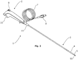
- FIG. 2 an assembled endoscope 1 according to the present invention is shown.
- the endoscope 1 has a proximal end with an operating handle 2 to be held in one hand by an operator. Accordingly, the operating handle is shaped in a manner ergonomically suitable for operator, in particular but not exclusively for the hand of the operator, as arms and joints may also play a role in the ergonomics.
- an insertion tube 3 extends towards the distal end of the endoscope.
- the insertion tube 3 ends in a bending section 4 and a tip part 5.
- the bending section 4 is in mechanical connection with a first operating member 6, digitally operable by the operator, e.g.
- the endoscope 1 comprises a tool operating member 22 adapted to operate a tool 55 at the tip part 5 of the endoscope 1 handle comprises.
- the tool operating member 22 is preferably in the form of a trigger or push-button so accommodated in the housing that it may be operated by the same hand as used for operating first operating member 6.
- the first operating member 6 is adapted to be operated by the thumb of the operator whereas the push-button is adapted to be depressed independently thereof by the index finger of the very same hand of the operator.
- the push-button is has been partially depressed allowing the tool 55 to be advanced forwardly from the distal end of the tip 5 of the endoscope 1.
- This partially depressed position which will be described in greater detail later is an intermediate position between the fully released position or rest position shown in Fig. 4a , towards which the push-button is preferably spring biased, and the fully depressed position shown in Fig. 4b , which will also be described later.
- the tool 55 is retracted in the distal tip, i.e. the forceps of the exemplary embodiment are closed as shown in Fig. 15b .
- the endoscope is illustrated with the tool operating member 22 partly depressed in the intermediate position between the rest position and the fully depressed position, wherein the tool 55 is in a corresponding extended position, i.e. extended out of the tip and hence the forceps of the exemplary embodiment are open and ready to grip and object.
- the tool 55 is still extended out of the tip and positioned in a task position, i.e. the forceps of the exemplary embodiment may be closed around an object to be removed.
- the endoscope 1 comprises a flexible connection cable 7 with a connector 8 allowing the endoscope 1 to be connected to a monitoring device such as a monitor 92 shown in Fig. 3 forming part of an endoscope 1 and monitor 92 system.
- the endoscope 1 has an operating handle 2 at the proximal end thereof i.e. at the left-hand side of Fig. 1a .
- the operating handle 2 is assembled from and comprises a number of handle parts to be described later.
- the insertion tube 3 comprising a number of insertion tube parts to be described later extends towards the distal end of the endoscope, i.e. towards the right-hand side of Fig. 1b .
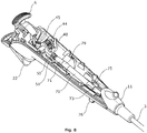
- the operating handle 2 comprises at least two shell parts 9, 10 forming the outer housing walls of the handle housing of the operating handle 2.
- the two shell parts 9, 10 form the outer housing walls and are shaped to provide an ergonomically suitable operating handle for an operator, gripping it with one hand.
- a transition part 11 forming the transition from the operating handle to the insertion tube 3, may be provided. This transition part may also form part of the handle housing.
- the two shell parts 9, 10 constitute the major part of the housing in the embodiment shown.
- the shell parts 9, 10 and almost all other parts are mounted on a chassis 12.
- the chassis 12 preferably shell shaped, i.e. the chassis 12 comprises an essentially shell shaped structure with a shell wall having an inner surface 16 and an outer surface 17 linked by an edge 18, said essentially shell shaped structure defining an interior compartment 19 delimited by said inner surface 16 and the edge 18 of the shell wall, the edge thus defining main opening 20 of said interior compartment 19.
- the chassis 12 can be designed mainly based on technical requirements, in such as kinematic chains of movable parts to be described further below, and thus be optimized for those technical requirements without having to inherit constraints from the ergonomic requirements of the handle 2, i.e. the shape of the two shell parts 9, 10.
- the chassis 12 is adapted to for the mounting of almost all parts of the endoscope 1.
- the chassis 12 is adapted for holding movable parts forming of kinematic chain from the push-button forming the tool operating member to the motion transfer means transferring the movement of the tool operating member 22 to the tool 55.
- a pair apertures 41 in the form of essentially cylindrical through holes can be seen in Fig. 1a .
- the apertures 41 serve as bearings of trunnions 42 carrying rotary member such as a pinion 44, best visible in Fig. 9 .
- the pinion 44 is adapted to be in engagement with a curved rack 45.
- the curved rack 45 is shown separately in Fig. 10 .
- the curved rack 45 has a first free end 46 and a second end with trunnions 47 held loosely in suitable receptacles inside the push button forming the tool operating member 22.
- the rack 45 as such is loosely held in a guideway comprising a first side 85, a second side 86 and a curved bottom 87 adapted to keep the rack 45 in engagement with the pinion 44.
- the first side 85 and the second side 86 as well as the curved bottom 87 are preferably formed integrally with the remainder of the chassis 12, e.g. in an injection moulding process.
- the first side is preferably constituted by a plane surface of a thickened part of the wall, i.e. a raised part of the inner surface 16 of the chassis 12.
- Rotation of the pinion 44 may be effected by an operator moving the push-button forming the tool operating member 22, e.g. depressing it using an index finger, upon which the push-button forming the tool operating member 22 transfer motion to the curved rack 45, in turn rotating the pinion 44.
- levers 48 and 49 are provided on the pinion 44. These levers 48 and 49 are in rigid connection with the pinion 44.
- the levers 48 and 49 have different lengths so as to influence a first motion transfer member 53 and a second transfer member 54 of the motion transfer means in different ways in order to effect a compound movement of the tool 55.
- this compound movement comprises both a linear movement of the tool 55 and a task movement of the tool 55.
- the first motion transfer member 53 is arranged co-axially within the second motion transfer member 54.
- the first motion transfer member 53 and the second motion transfer member 54 are arranged within in tubular members 71, 72, 73, 74, which form part of the working channel of the endoscope, together with an e.g. T- or Y-shaped bifurcated section 75 providing the entry port to the working channel.
- the first and second motion transfer members 53, 54 each comprise different sectors with different rigidities or bending properties, matching the requirements of the insertion tube 3, and the working channel, which both also has different bending properties along the length thereof.
- the first motion transfer member 53 preferably comprises a rigid rod piece at the proximal end and a rod or tubular piece at the tool 55. Between the two, the first motion transfer means may comprise a flexible wire.
- the first motion transfer member 53 is terminated in an end sealing means 51. Apart from sealing the proximal end of the working channel, the end sealing means also serves as part a first kinematic chain by being pivotally connected to the first lever 48.
- the first kinematic chain is as follows: Depressing the tool operating member 22 will move the rack 45 in a curvilinear movement via the trunnions 47.
- the rack 45 which has teeth in permanent engagement with the pinion 44, will rotate the pinion 44 and the first lever 48 rigidly connected thereto.
- the rotating first lever will consequently push the proximal end of the first motion transfer member 53, causing the tool 55 arranged at distal end of the first motion transfer member 31 to be moved out of the working channel beyond the distal end of the insertion tube 3 of the endoscope 1.
- the second motion transfer member 54 forms a sheath for the first motion transfer member and preferably comprises a coil spring part 54a wound from wire with a rectangular cross section towards the proximal end, and a coil spring part 54b wound from wire with a circular or round cross section towards the distal end. At the distal end, the second motion transfer member is terminated in a rigid tubular member 95.
- the second motion transfer member 54 is terminated in a first tubular end member 52.
- the rigid part of the first motion transfer member 53 passes co-axially trough the first tubular end member 52 and into the remainder of the second motion transfer member 54.
- the passage through the first tubular end member 52 as well as through the remainder of the second motion transfer member 54 is adapted to allow mutual lengthwise relative motion, i.e. mutually reciprocating movement.
- the first tubular end member 52 serves as part of a second kinematic chain adapted to provide a different motion pattern of the second motion transfer member 54 as compared to the first motion transfer member 53 in response to the very same depression, i.e. one and the same as the one described above.
- a first arm 50 is provided in articulated connection with said second lever 49.
- the second end of the first arm 50 is in articulated connection with a clamping means 79 adapted to clamp the tubular end means 52 with a part 71 of the working channel wall interposed.
- the interposed part 71 is preferably a flexible hose part.
- the flexible hose part is made from the very same tubular material as is used to form the outer sheath 80 of the insertion tube 3 at the distal end around the bending portion 4.
- the first tubular end member may comprise concentric ribs 98 or corrugations, or similar means.
- the articulations of the first arm 50 are preferably provided as integrally moulded foil hinges 93, as best seen in Fig. 12 .
- the clamping means 79 and/or the flexible hose part 71 abuts a mounting plate 59, which adapted to carry electronic circuitry of the endoscope.
- the mounting plate 59 serves as a strike plate that may limit the movement of the second kinematic chain.
- the mounting plate 59 may be provided with a lid so to seal the electronic circuity.
- the second kinematic chain is as follows: Depressing the tool operating member 22 will move the rack 45 in a curvilinear movement via the tool trunnions 47.
- the rack 45 which has teeth in permanent engagement with the pinion 44, will rotate the pinion 44 and the second lever 49 rigidly connected thereto, so as to change their relative position while remaining in the engagement.
- the rotating second lever 49 will consequently push the proximal end of the first arm 50, thereby moving clamping means 79 at distal end of the first arm 50, articulating the first arm 50 as necessary in the foil hinges 93.
- the clamping means 79 moves the clamped part of the working channel wall part 71.
- the clamped part of the working channel wall 71 moves the first tubular end member of the second motion transfer member 54 towards the distal end of the working channel, consequently causing the distal end of the second motion transfer member 54 to be moved out of the working channel beyond the distal end of the insertion tube 3 of the endoscope 1.
- the distal end of the second motion transfer member 54 is preferably terminated in a second tubular end member 95.
- Providing these two different kinematic chains allows the tool 55 to perform a compound movement comprising both a linear movement and a task movement, during one continuous depression of the tool operating member 22.
- the tool 55 is advanced to a position in front of the distal end of the insertion tube 3 of endoscope 1 where it is visible from the camera built into the tip part 5 of the endoscope 1, and hence visible by the operator on the monitor 92 attached to the endoscope via cable 7 and connector. This may be performed by only partially depressing the tool operating member 22, e.g. to the position shown in Fig.
- the task movement can be performed.
- the tool 55 at the distal end of the first motion transfer member 53 comprises a self expanding configuration, such as a pair of spring tweezers, forceps, a spring loop, or the like which as long as it is accommodated in the tubular member 95 is compressed, as shown in Fig. 15b . Accordingly, it will auto-expand if it is advanced out the second tubular member 95, to the configuration shown in Fig. 2 .
- the second motion transfer member is held stationary is in the working channel during the first part of the depression of the tool operating means 22 to the intermediate position.
- the object may then be removed from the body by retracting the entire endoscope 1 from the cavity whilst holding the tool operating member 22 depressed.
- continuous movement is merely to be understood as a movement of the tool operating member from released state to a depressed state. It does not imply that the movement cannot be paused by the operator during the continuous movement. It does also not imply that the movement cannot be partially reversed by the operator releasing the tool operating member 22, in the search for the gripping location.
- a latch means may be included to partially intermit the procedure without the tool changing its position. This could be a simple click mechanism as is well known in the art, latching when the tool operating member 22 is depressed fully, and releasing upon repeated depression of the tool operating member 22.
- the rack 45 has a curvature.
- This curvature preferably matches the curvature of the curved bottom 87 of the guideway, so that the teeth of the rack 45 are kept in engagement with the matching teeth of the pinion 44.
- This curvature saves space helping to fit the rack 45 and pinion 44 mechanism within the chassis 12 and the handle housing 2.
- the pinion 44 with a generally oval shape or other curvature is also envisaged.
- the two kinematic chains, and in particular their mutual differences could be influenced by suitable choice of the length of the levers 48 and 49, their angular spacing on the pinion 44, and the length and articulations of the arm 50, as well as by the provision of further arms. This may allow specific adaptation of the kinematic chains to the specific requirements of different tools 55.
- first and second motion transfer members are located within the working channel of the endoscope 1, comprising tubular members 71, 72, 73, 74 forming a generally tubular working channel wall and an e.g. T- or Y-shaped bifurcated section 75 providing the entry port to the working channel.
- a first tubular member 72 adapted to comply with the bending requirements of the bending section 4 of the endoscope 1 is provided.
- the first tubular member 72 passes through the bending section and thus provides an exit port 96 of the working channel at the tip 5 thereof.
- a second tubular member 73 is joined at one end with the first tubular member 72 and provides a longer intermediate section of the working channel.
- the second tubular member 73 is generally more rigid than the first tubular member 72.
- the second tubular member 73 is however still quite flexible. More specifically, the second tubular member 73 and a second outer tube section 81 surrounding it are so flexible that they allow a loose knot to be tied on the insertion tube 3.
- the alternative is a rigid or semi-rigid endoscope where the insertion portion is rigid, only slightly bendable or hinged, and which does not allow a knot to be tied on the insertion tube. It is preferred to make the first tubular member 71 of a first polyurethane elastomer and to make the first tubular member 72 of another polyurethane elastomer. Both polyturethane elastomers could be Pellethane®, which is available in different variants.
- the second tube member 73 may also comprise polyurethane. At the other end of the second tubular member 73, the second tubular member 73 is joined to a first branch of a preferably T-shaped bifurcated section 75.
- the bifurcated section has s second branch which provides the entry port to the working channel together with a connector 76 or lead-in mounted on the chassis 12.
- the bifurcated section is 75 T-shaped. That is to say perpendicular that the second branch is perpendicular to the first branch.
- the second branch could also be arranged a different angle, so as to provide more of a Y-shape.
- the connector 76 allows a suction means to be attached for extracting fluid from a body cavity via the working channel.
- a fluid source may be attached to the connector 76, allowing e.g. irrigation or aspiration of the body cavity via the working channel.
- the third branch of the bifurcated section 75 is preferably aligned with the first branch so as to provide an unobstructed straight passage through the bifurcated section 75 for the first and second motion transfer members 53, 54.
- a firs end of a third tubular member is attached, which at least in the released position of the operating member 22 is aligned with the first and third branch of the bifurcated section 75 and the second tubular member 73, when the latter is in a relaxed position, i.e. not influenced by external forces from body cavity walls or he like.
- the second end of the third tubular member 71 forms the proximal end of the working channel, and is terminated in an end sealing means 51.
- the third tubular member 71 is preferably in the form of a hose of a highly flexible material, as compared to the remainder of the tubular members forming the working channel.
- the hose could be provided with corrugations or the like to from a bellows. Making the third tubular member of a highly flexible material serves two purposes.
- the first purpose is that it allows the length of the working channel to adapt to the movement of the members of the first kinematic chain in particular the first lever 48, the first motion transfer member 53 and the interposed end sealing member 51.
- the flexible material allows the working channel to deform in order to adapt in length to accommodate the movement of the first motion transfer member.
- the material also allows working channel to deform in order to comply with the swinging movement of the end sealing member caused by the first lever 48 moving the end sealing member 51 out of alignment with the first and third branches of the bifurcated member 75 and second tubular member 73.
- the third tubular member 71 allows transfer of movement using parts of the working cannel itself, in turn, allowing transfer of movement from the operating means 22 to the tool 55 without breaching the integrity of working channel wall. Undesired ingress of pollutants is thus avoided.
- the second purpose is similar to the first purpose, because by being flexible the material also allows working channel to deform in order to comply with the movement of the members of the second kinematic chain, in particular the movement of the first tubular end member 52 caused by the second lever 49 in conjunction with the arm first 50. As mentioned above this movement is transferred via the working channel wall, because the third tubular member 72 is clamped between the first tubular end member 52 and clamping member 79. By being able to comply with these movements, the third tubular member 71 allows transfer of movement using parts of the working cannel itself, in turn, allowing transfer of movement from the operating means 22 to the tool 55 without breaching the integrity of working channel wall. Undesired ingress of pollutants is thus avoided.
- the first tubular end member 52 may comprise concentric ribs 98 or corrugations, or similar means.
- a second problem is with this configuration of the working channel with a sealed appendix at the proximal end, the output port at the distal end, and entry port located between them, it becomes difficult to sterilize the interior of the appendix, in particular the proximal end thereof between the end sealing means 51 and the first tubular end member 52, because the access of sterilizing fluid, such as Ethylene Oxide, may be blocked by the first tubular end member 52.
- Sterilisation with Ethylene Oxide is preferred for sterilisation, because the endoscope 1 according to the invention is preferably a disposable endoscope made from low cost materials, which may not necessarily withstand other sterilization processes such as the high temperature and pressure of an autoclave sterilisation.
- an elongate groove along the first tubular end member 52 and across the concentric ribs 98 is provided.
- this groove is made to register with gap in the clamping means 79, so as to allow an open fluid passage along the first tubular end member 52.
- the inner diameter of the third tubular member 71 is selected to be larger than the largest outer diameter of the first tubular end member 52 so as to form a pouch in the first tubular member 71 also registering with the groove 99.
Applications Claiming Priority (3)
| Application Number | Priority Date | Filing Date | Title |
|---|---|---|---|
| DKPA201570321 | 2015-05-27 | ||
| DKPA201570320 | 2015-05-27 | ||
| PCT/DK2016/050153 WO2016188542A1 (en) | 2015-05-27 | 2016-05-26 | An endoscope |
Publications (2)
| Publication Number | Publication Date |
|---|---|
| EP3302217A1 EP3302217A1 (en) | 2018-04-11 |
| EP3302217B1 true EP3302217B1 (en) | 2020-06-03 |
Family
ID=63998419
Family Applications (1)
| Application Number | Title | Priority Date | Filing Date |
|---|---|---|---|
| EP16726781.4A Active EP3302217B1 (en) | 2015-05-27 | 2016-05-26 | An endoscope |
Country Status (4)
| Country | Link |
|---|---|
| US (1) | US10624531B2 (zh) |
| EP (1) | EP3302217B1 (zh) |
| CN (2) | CN107809941B (zh) |
| WO (2) | WO2016188541A1 (zh) |
Families Citing this family (34)
| Publication number | Priority date | Publication date | Assignee | Title |
|---|---|---|---|---|
| US10321804B2 (en) | 2013-01-07 | 2019-06-18 | Ambu A/S | Articulated tip part for an endoscope |
| WO2016188543A1 (en) | 2015-05-27 | 2016-12-01 | Ambu A/S | An endoscope with a tool |
| EP3302213B1 (en) | 2015-05-27 | 2022-11-23 | Ambu A/S | Endoscope |
| WO2016188539A1 (en) | 2015-05-27 | 2016-12-01 | Ambu A/S | An endoscope |
| EP3302216B1 (en) | 2015-05-27 | 2019-04-17 | Ambu A/S | An endoscope |
| EP3302214B1 (en) | 2015-05-27 | 2019-07-31 | Ambu A/S | An endoscope comprising a chassis having a shell structure |
| US10617284B2 (en) | 2015-05-27 | 2020-04-14 | Ambu A/S | Endoscope |
| CN109788886A (zh) | 2016-09-28 | 2019-05-21 | 安布股份有限公司 | 适于促进bal过程的内窥镜 |
| EP3544482A4 (en) | 2016-11-28 | 2020-07-22 | Adaptivendo LLC | SEPARABLE DISPOSABLE SHAFT ENDOSCOPE |
| CN110234263B (zh) | 2017-03-08 | 2022-04-08 | 安布股份有限公司 | 用于内窥镜的手柄 |
| WO2018162556A1 (en) | 2017-03-08 | 2018-09-13 | Ambu A/S | A handle for an endoscope |
| US11484296B2 (en) | 2017-05-02 | 2022-11-01 | Ambu A/S | Endoscope |
| EP3417758A1 (en) | 2017-06-19 | 2018-12-26 | Ambu A/S | A method for processing image data using a non-linear scaling model and a medical visual aid system |
| WO2019002186A1 (en) | 2017-06-26 | 2019-01-03 | Ambu A/S | BENDING SECTION FOR ENDOSCOPE |
| USD898910S1 (en) | 2017-08-25 | 2020-10-13 | Ambu A/S | Medical scope |
| CN111093463A (zh) | 2017-09-28 | 2020-05-01 | 安布股份有限公司 | 内窥镜 |
| EP3494862A1 (en) | 2017-12-08 | 2019-06-12 | Ambu A/S | Illumination system for an endoscope |
| EP3513706A1 (en) | 2018-01-19 | 2019-07-24 | Ambu A/S | A method for fixation of a wire portion of an endoscope, and an endoscope |
| EP3517017B1 (en) | 2018-01-26 | 2023-01-18 | Ambu A/S | A method for fixation of a wire portion of an endoscope, and an endoscope |
| EP3613326B1 (en) | 2018-08-24 | 2023-09-20 | Ambu A/S | A tip part for a vision device |
| US11311184B2 (en) | 2018-08-24 | 2022-04-26 | Ambu A/S | Tip part for a vision device |
| EP3613327A1 (en) | 2018-08-24 | 2020-02-26 | Ambu A/S | A tip part for a vision device |
| EP3876818A1 (de) * | 2018-11-07 | 2021-09-15 | Richard Wolf GmbH | Endoskopisches instrument |
| USD1018844S1 (en) | 2020-01-09 | 2024-03-19 | Adaptivendo Llc | Endoscope handle |
| US10980397B1 (en) | 2020-02-21 | 2021-04-20 | Ambu A/S | Video processing device |
| US11109741B1 (en) | 2020-02-21 | 2021-09-07 | Ambu A/S | Video processing apparatus |
| US10835106B1 (en) | 2020-02-21 | 2020-11-17 | Ambu A/S | Portable monitor |
| US11166622B2 (en) | 2020-02-21 | 2021-11-09 | Ambu A/S | Video processing apparatus |
| GB202002913D0 (en) * | 2020-02-28 | 2020-04-15 | Duckworth And Kent Ltd | Ophthalmic instrument |
| WO2021249601A1 (en) | 2020-06-08 | 2021-12-16 | Ambu A/S | A sliding motion transfer member for an endoscope |
| EP3925512A1 (en) | 2020-06-19 | 2021-12-22 | Ambu A/S | An endoscope comprising an articulated bending section body |
| US11324394B2 (en) | 2020-09-15 | 2022-05-10 | Ambu A/S | Endoscope |
| EP4011270A1 (en) | 2020-12-08 | 2022-06-15 | Ambu A/S | Endoscope tip part with improved optical properties |
| WO2024035855A1 (en) * | 2022-08-11 | 2024-02-15 | Boston Scientific Scimed, Inc. | Medical device with integrated instrument and related methods |
Family Cites Families (90)
| Publication number | Priority date | Publication date | Assignee | Title |
|---|---|---|---|---|
| US609370A (en) | 1898-08-16 | John w | ||
| US609570A (en) | 1898-08-23 | bowden | ||
| US4203430A (en) | 1976-12-16 | 1980-05-20 | Nagashige Takahashi | Device for controlling curvature of an end section in an endoscope |
| US5421819A (en) | 1992-08-12 | 1995-06-06 | Vidamed, Inc. | Medical probe device |
| US5435805A (en) | 1992-08-12 | 1995-07-25 | Vidamed, Inc. | Medical probe device with optical viewing capability |
| JPS6233801U (zh) * | 1985-08-14 | 1987-02-27 | ||
| US4757827A (en) | 1987-02-17 | 1988-07-19 | Versaflex Delivery Systems Inc. | Steerable guidewire with deflectable tip |
| JPH069540B2 (ja) | 1987-04-03 | 1994-02-09 | オリンパス光学工業株式会社 | 内視鏡 |
| JPH03264041A (ja) | 1990-03-14 | 1991-11-25 | Machida Endscope Co Ltd | 湾曲操作装置 |
| US5275151A (en) | 1991-12-11 | 1994-01-04 | Clarus Medical Systems, Inc. | Handle for deflectable catheter |
| DE4201280C1 (zh) | 1992-01-18 | 1992-12-10 | Richard Wolf Gmbh, 7134 Knittlingen, De | |
| US5417203A (en) | 1992-04-23 | 1995-05-23 | United States Surgical Corporation | Articulating endoscopic surgical apparatus |
| US5462527A (en) | 1993-06-29 | 1995-10-31 | C.R. Bard, Inc. | Actuator for use with steerable catheter |
| US5373317B1 (en) * | 1993-05-28 | 2000-11-21 | Welch Allyn Inc | Control and display section for borescope or endoscope |
| US5450851A (en) * | 1994-05-25 | 1995-09-19 | Advanced Technology Laboratories, Inc. | Ultrasonic probe assembly |
| JP3499972B2 (ja) | 1995-06-28 | 2004-02-23 | ペンタックス株式会社 | 内視鏡 |
| US5810876A (en) | 1995-10-03 | 1998-09-22 | Akos Biomedical, Inc. | Flexible forceps device |
| US6007531A (en) | 1995-11-21 | 1999-12-28 | Catheter Imaging Systems, Inc. | Steerable catheter having disposable module and sterilizable handle and method of connecting same |
| US5868664A (en) | 1996-02-23 | 1999-02-09 | Envision Medical Corporation | Electrically isolated sterilizable endoscopic video camera head |
| US5879289A (en) | 1996-07-15 | 1999-03-09 | Universal Technologies International, Inc. | Hand-held portable endoscopic camera |
| US5938588A (en) | 1997-06-25 | 1999-08-17 | Circon Corporation | Superelastic control wire sheath for flexible endoscope |
| US6270508B1 (en) | 1998-10-26 | 2001-08-07 | Charles H. Klieman | End effector and instrument for endoscopic and general surgery needle control |
| US6077277A (en) | 1999-04-05 | 2000-06-20 | Starion Instruments, Inc. | Suture welding device |
| US6258101B1 (en) | 2000-03-24 | 2001-07-10 | Lacey Manufacturing Company, Inc. | Instrument for deploying surgical devices |
| JP2002177199A (ja) | 2000-10-02 | 2002-06-25 | Olympus Optical Co Ltd | 内視鏡 |
| US8021372B2 (en) | 2001-07-05 | 2011-09-20 | Annex Medical, Inc. | Medical retrieval device with independent rotational means |
| US8133171B2 (en) | 2003-06-02 | 2012-03-13 | Karl Storz Endovision, Inc. | Wire spring guide for flexible endoscope |
| EP1661505B1 (en) | 2003-09-05 | 2014-12-31 | Olympus Corporation | Endoscope |
| US7789825B2 (en) * | 2003-09-29 | 2010-09-07 | Ethicon Endo-Surgery, Inc. | Handle for endoscopic device |
| DE10346598A1 (de) | 2003-10-07 | 2005-05-04 | Henke Sass Wolf Gmbh | Elektronisches Endoskop |
| JP4504696B2 (ja) | 2004-02-03 | 2010-07-14 | オリンパス株式会社 | 内視鏡用処置具及び内視鏡並びに内視鏡処置システム |
| GB2414185A (en) | 2004-05-20 | 2005-11-23 | Gyrus Medical Ltd | Morcellating device using cutting electrodes on end-face of tube |
| US7678117B2 (en) | 2004-06-07 | 2010-03-16 | Novare Surgical Systems, Inc. | Articulating mechanism with flex-hinged links |
| US7300397B2 (en) | 2004-07-29 | 2007-11-27 | C2C Cure, Inc. | Endoscope electronics assembly |
| US7846107B2 (en) | 2005-05-13 | 2010-12-07 | Boston Scientific Scimed, Inc. | Endoscopic apparatus with integrated multiple biopsy device |
| US9289112B2 (en) | 2006-01-13 | 2016-03-22 | Olympus Corporation | Medical treatment endoscope having an operation stick formed to allow a procedure instrument to pass |
| US20070219411A1 (en) | 2006-01-13 | 2007-09-20 | Olympus Medical Systems Corp. | Overtube and endoscopic treatment system |
| US8021293B2 (en) | 2006-01-13 | 2011-09-20 | Olympus Medical Systems Corp. | Medical treatment endoscope |
| US8202265B2 (en) * | 2006-04-20 | 2012-06-19 | Boston Scientific Scimed, Inc. | Multiple lumen assembly for use in endoscopes or other medical devices |
| WO2007136754A2 (en) | 2006-05-19 | 2007-11-29 | Boston Scientific Limited | Control mechanism for steerable medical device |
| KR101477121B1 (ko) | 2006-06-13 | 2014-12-29 | 인튜어티브 서지컬 인코포레이티드 | 미소절개 수술 시스템 |
| US8678999B2 (en) | 2006-09-11 | 2014-03-25 | Karl Storz Endovision, Inc. | System and method for a hysteroscope with integrated instruments |
| WO2008045374A2 (en) | 2006-10-05 | 2008-04-17 | Tyco Healthcare Group Lp | Handle assembly for articulated endoscopic instruments |
| US20100030020A1 (en) | 2006-10-20 | 2010-02-04 | Femsuite Llc | Optical surgical device and method of use |
| US9055863B2 (en) | 2006-11-14 | 2015-06-16 | Optim, Inc. | Portable endoscope |
| US9289266B2 (en) | 2006-12-01 | 2016-03-22 | Boston Scientific Scimed, Inc. | On-axis drive systems and methods |
| US9326665B2 (en) | 2007-01-09 | 2016-05-03 | Medtronic Xomed, Inc. | Surgical instrument, system, and method for biofilm removal |
| EP2114266B1 (en) | 2007-02-09 | 2014-08-06 | Skeletal Dynamics, LLC | Endo-surgical device |
| JP2008264253A (ja) | 2007-04-20 | 2008-11-06 | Olympus Medical Systems Corp | 医療用処置具及び内視鏡処置システム |
| US8137263B2 (en) * | 2007-08-24 | 2012-03-20 | Karl Storz Endovision, Inc. | Articulating endoscope instrument |
| US8152715B2 (en) | 2007-09-14 | 2012-04-10 | Optim, Incorporated | Endoscope with internal light source and power supply |
| US9707003B2 (en) | 2007-10-02 | 2017-07-18 | Covidien Lp | Articulating surgical instrument |
| WO2009092067A2 (en) | 2008-01-18 | 2009-07-23 | Neurosystec Corporation | Valveless impedance pump drug delivery systems |
| DE102008017300A1 (de) | 2008-03-31 | 2009-10-01 | Karl Storz Gmbh & Co. Kg | Medizinisches Instrument mit arretierbarer Abwinkelsteuerung |
| US20110009694A1 (en) | 2009-07-10 | 2011-01-13 | Schultz Eric E | Hand-held minimally dimensioned diagnostic device having integrated distal end visualization |
| WO2010066790A1 (en) | 2008-12-10 | 2010-06-17 | Ambu A/S | Endoscope having a camera housing and method for making a camera housing |
| JP5484483B2 (ja) | 2008-12-10 | 2014-05-07 | アンブ・エ/エス | 内視鏡の屈曲部分制御機構 |
| CN102271571A (zh) | 2008-12-10 | 2011-12-07 | 阿姆布股份有限公司 | 具有弯曲部的内镜 |
| US20100249497A1 (en) | 2009-03-30 | 2010-09-30 | Peine William J | Surgical instrument |
| DE102009018638A1 (de) | 2009-04-17 | 2010-10-21 | Karl Storz Gmbh & Co. Kg | Medizinisches Instrument mit einer drehbaren Rastsperre |
| US20100298642A1 (en) | 2009-05-19 | 2010-11-25 | Ethicon Endo-Surgery, Inc. | Manipulatable guide system and methods for natural orifice translumenal endoscopic surgery |
| US20110112517A1 (en) * | 2009-11-06 | 2011-05-12 | Peine Willliam J | Surgical instrument |
| GB2479176B (en) | 2010-03-31 | 2015-12-23 | Gyrus Medical Ltd | Surgical instrument |
| WO2011163520A2 (en) * | 2010-06-25 | 2011-12-29 | Kieturakis Maciej J | Single port laparoscopic access with laterally spaced virtual insertion points |
| US9592094B2 (en) | 2011-05-12 | 2017-03-14 | Imperial Innovations Limited | Surgical device and component having movable plug portions |
| CN102283684B (zh) * | 2011-09-24 | 2013-08-14 | 天津博朗科技发展有限公司 | 一次性双通道内窥镜镜鞘 |
| US9693759B2 (en) | 2011-11-16 | 2017-07-04 | Coloplast A/S | Operating device with a control handle and a flexible element connected to the control handle |
| WO2013106444A1 (en) | 2012-01-10 | 2013-07-18 | Boston Scientific Scimed, Inc. | A steerable medical device having an imaging system |
| DE102012108076A1 (de) | 2012-08-31 | 2014-03-06 | Karl Storz Gmbh & Co. Kg | Schaft für ein flexibles Endoskop oder ein flexibles endoskopisches Instrument |
| US8894610B2 (en) | 2012-11-28 | 2014-11-25 | Hansen Medical, Inc. | Catheter having unirail pullwire architecture |
| US9907457B2 (en) | 2013-02-01 | 2018-03-06 | Deka Products Limited Partnership | Endoscope with pannable camera |
| WO2014127780A1 (en) | 2013-02-22 | 2014-08-28 | Ambu A/S | Means for maintaining a tensioned pull-wire in an endoscope |
| US9895055B2 (en) | 2013-02-28 | 2018-02-20 | Cook Medical Technologies Llc | Medical devices, systems, and methods for the visualization and treatment of bodily passages |
| US20140275763A1 (en) | 2013-03-15 | 2014-09-18 | Lucent Medical Systems, Inc. | Partially disposable endoscopic device |
| US10076231B2 (en) * | 2013-04-22 | 2018-09-18 | Gyrus Acmi, Inc. | Surgeon controlled endoscope device and method |
| CN203506676U (zh) | 2013-08-30 | 2014-04-02 | 李向东 | 牵引拉动式内窥镜 |
| CN103445855A (zh) * | 2013-09-18 | 2013-12-18 | 天津博朗科技发展有限公司 | 内窥镜镜鞘的伸缩密封机构 |
| CN103505176B (zh) | 2013-09-18 | 2015-04-29 | 天津博朗科技发展有限公司 | 具有一次性锁紧机构的可调节长度的内窥镜镜鞘 |
| WO2015064412A1 (ja) | 2013-10-31 | 2015-05-07 | オリンパスメディカルシステムズ株式会社 | 医療機器 |
| CN203885470U (zh) | 2014-02-15 | 2014-10-22 | 牛夕华 | 多功能内阴治疗器 |
| IL231054A (en) | 2014-02-20 | 2015-07-30 | Tzony Siegal | A device for advancing along a curved track and a method for its operation |
| EP3125740B1 (en) | 2014-04-04 | 2023-07-26 | Boston Scientific Scimed, Inc. | Medical system and related methods for diagnosis and treatment |
| CN204120980U (zh) | 2014-09-26 | 2015-01-28 | 吴江市江南不锈钢器材有限责任公司 | 一种金属软管探测夹取装置 |
| WO2016057225A1 (en) | 2014-10-07 | 2016-04-14 | Covidien Lp | Handheld electromechanical surgical system |
| US10617284B2 (en) | 2015-05-27 | 2020-04-14 | Ambu A/S | Endoscope |
| WO2016188539A1 (en) | 2015-05-27 | 2016-12-01 | Ambu A/S | An endoscope |
| EP3302214B1 (en) | 2015-05-27 | 2019-07-31 | Ambu A/S | An endoscope comprising a chassis having a shell structure |
| WO2016188543A1 (en) | 2015-05-27 | 2016-12-01 | Ambu A/S | An endoscope with a tool |
| EP3302213B1 (en) | 2015-05-27 | 2022-11-23 | Ambu A/S | Endoscope |
| EP3302216B1 (en) | 2015-05-27 | 2019-04-17 | Ambu A/S | An endoscope |
-
2016
- 2016-05-26 WO PCT/DK2016/050152 patent/WO2016188541A1/en active Application Filing
- 2016-05-26 CN CN201680039147.9A patent/CN107809941B/zh active Active
- 2016-05-26 CN CN201680038440.3A patent/CN107809938B/zh active Active
- 2016-05-26 WO PCT/DK2016/050153 patent/WO2016188542A1/en active Application Filing
- 2016-05-26 EP EP16726781.4A patent/EP3302217B1/en active Active
- 2016-05-26 US US15/576,814 patent/US10624531B2/en active Active
Non-Patent Citations (1)
| Title |
|---|
| None * |
Also Published As
| Publication number | Publication date |
|---|---|
| EP3302217A1 (en) | 2018-04-11 |
| CN107809941B (zh) | 2020-05-12 |
| CN107809938B (zh) | 2020-06-16 |
| CN107809941A (zh) | 2018-03-16 |
| CN107809938A (zh) | 2018-03-16 |
| US10624531B2 (en) | 2020-04-21 |
| US20180303315A1 (en) | 2018-10-25 |
| WO2016188542A1 (en) | 2016-12-01 |
| WO2016188541A1 (en) | 2016-12-01 |
Similar Documents
| Publication | Publication Date | Title |
|---|---|---|
| EP3302217B1 (en) | An endoscope | |
| EP3302216B1 (en) | An endoscope | |
| US11337588B2 (en) | Endoscope | |
| US10646107B2 (en) | Endoscope with a tool | |
| US10507126B2 (en) | Endoscope having a grasping tool and a method for removing a stent from a patient | |
| US20110230706A1 (en) | Surgical manipulator | |
| JP6290376B2 (ja) | 外科医制御内視鏡装置 | |
| US20190209149A1 (en) | Control assemblies for medical devices and related methods of use | |
| EP2842503A1 (en) | Laparoscopic surgical instrument | |
| EP3302316B1 (en) | An endoscope | |
| EP3949879A1 (en) | Laparoscopic surgical instrument | |
| EP3518723B1 (en) | A set comprising an endoscope and a work tool unit | |
| JPWO2016092983A1 (ja) | 補助具及び内視鏡システム | |
| JP2004255080A (ja) | 外科用処置具 |
Legal Events
| Date | Code | Title | Description |
|---|---|---|---|
| STAA | Information on the status of an ep patent application or granted ep patent |
Free format text: STATUS: THE INTERNATIONAL PUBLICATION HAS BEEN MADE |
|
| PUAI | Public reference made under article 153(3) epc to a published international application that has entered the european phase |
Free format text: ORIGINAL CODE: 0009012 |
|
| STAA | Information on the status of an ep patent application or granted ep patent |
Free format text: STATUS: REQUEST FOR EXAMINATION WAS MADE |
|
| 17P | Request for examination filed |
Effective date: 20171213 |
|
| AK | Designated contracting states |
Kind code of ref document: A1 Designated state(s): AL AT BE BG CH CY CZ DE DK EE ES FI FR GB GR HR HU IE IS IT LI LT LU LV MC MK MT NL NO PL PT RO RS SE SI SK SM TR |
|
| AX | Request for extension of the european patent |
Extension state: BA ME |
|
| DAV | Request for validation of the european patent (deleted) | ||
| DAX | Request for extension of the european patent (deleted) | ||
| STAA | Information on the status of an ep patent application or granted ep patent |
Free format text: STATUS: EXAMINATION IS IN PROGRESS |
|
| 17Q | First examination report despatched |
Effective date: 20181026 |
|
| REG | Reference to a national code |
Ref country code: DE Ref legal event code: R079 Ref document number: 602016037485 Country of ref document: DE Free format text: PREVIOUS MAIN CLASS: A61B0001000000 Ipc: A61B0001005000 |
|
| RIC1 | Information provided on ipc code assigned before grant |
Ipc: A61B 10/04 20060101ALI20191211BHEP Ipc: A61B 1/008 20060101ALI20191211BHEP Ipc: A61B 90/00 20160101ALN20191211BHEP Ipc: A61B 17/00 20060101ALN20191211BHEP Ipc: A61B 1/00 20060101ALN20191211BHEP Ipc: A61B 1/018 20060101ALI20191211BHEP Ipc: A61B 1/005 20060101AFI20191211BHEP Ipc: A61B 17/29 20060101ALI20191211BHEP |
|
| GRAP | Despatch of communication of intention to grant a patent |
Free format text: ORIGINAL CODE: EPIDOSNIGR1 |
|
| STAA | Information on the status of an ep patent application or granted ep patent |
Free format text: STATUS: GRANT OF PATENT IS INTENDED |
|
| INTG | Intention to grant announced |
Effective date: 20200124 |
|
| GRAS | Grant fee paid |
Free format text: ORIGINAL CODE: EPIDOSNIGR3 |
|
| GRAA | (expected) grant |
Free format text: ORIGINAL CODE: 0009210 |
|
| STAA | Information on the status of an ep patent application or granted ep patent |
Free format text: STATUS: THE PATENT HAS BEEN GRANTED |
|
| AK | Designated contracting states |
Kind code of ref document: B1 Designated state(s): AL AT BE BG CH CY CZ DE DK EE ES FI FR GB GR HR HU IE IS IT LI LT LU LV MC MK MT NL NO PL PT RO RS SE SI SK SM TR |
|
| REG | Reference to a national code |
Ref country code: GB Ref legal event code: FG4D |
|
| REG | Reference to a national code |
Ref country code: CH Ref legal event code: EP Ref country code: AT Ref legal event code: REF Ref document number: 1276128 Country of ref document: AT Kind code of ref document: T Effective date: 20200615 |
|
| REG | Reference to a national code |
Ref country code: DE Ref legal event code: R096 Ref document number: 602016037485 Country of ref document: DE |
|
| REG | Reference to a national code |
Ref country code: LT Ref legal event code: MG4D |
|
| PG25 | Lapsed in a contracting state [announced via postgrant information from national office to epo] |
Ref country code: SE Free format text: LAPSE BECAUSE OF FAILURE TO SUBMIT A TRANSLATION OF THE DESCRIPTION OR TO PAY THE FEE WITHIN THE PRESCRIBED TIME-LIMIT Effective date: 20200603 Ref country code: GR Free format text: LAPSE BECAUSE OF FAILURE TO SUBMIT A TRANSLATION OF THE DESCRIPTION OR TO PAY THE FEE WITHIN THE PRESCRIBED TIME-LIMIT Effective date: 20200904 Ref country code: NO Free format text: LAPSE BECAUSE OF FAILURE TO SUBMIT A TRANSLATION OF THE DESCRIPTION OR TO PAY THE FEE WITHIN THE PRESCRIBED TIME-LIMIT Effective date: 20200903 Ref country code: FI Free format text: LAPSE BECAUSE OF FAILURE TO SUBMIT A TRANSLATION OF THE DESCRIPTION OR TO PAY THE FEE WITHIN THE PRESCRIBED TIME-LIMIT Effective date: 20200603 Ref country code: LT Free format text: LAPSE BECAUSE OF FAILURE TO SUBMIT A TRANSLATION OF THE DESCRIPTION OR TO PAY THE FEE WITHIN THE PRESCRIBED TIME-LIMIT Effective date: 20200603 |
|
| REG | Reference to a national code |
Ref country code: NL Ref legal event code: MP Effective date: 20200603 |
|
| PG25 | Lapsed in a contracting state [announced via postgrant information from national office to epo] |
Ref country code: LV Free format text: LAPSE BECAUSE OF FAILURE TO SUBMIT A TRANSLATION OF THE DESCRIPTION OR TO PAY THE FEE WITHIN THE PRESCRIBED TIME-LIMIT Effective date: 20200603 Ref country code: HR Free format text: LAPSE BECAUSE OF FAILURE TO SUBMIT A TRANSLATION OF THE DESCRIPTION OR TO PAY THE FEE WITHIN THE PRESCRIBED TIME-LIMIT Effective date: 20200603 Ref country code: BG Free format text: LAPSE BECAUSE OF FAILURE TO SUBMIT A TRANSLATION OF THE DESCRIPTION OR TO PAY THE FEE WITHIN THE PRESCRIBED TIME-LIMIT Effective date: 20200903 Ref country code: RS Free format text: LAPSE BECAUSE OF FAILURE TO SUBMIT A TRANSLATION OF THE DESCRIPTION OR TO PAY THE FEE WITHIN THE PRESCRIBED TIME-LIMIT Effective date: 20200603 |
|
| REG | Reference to a national code |
Ref country code: AT Ref legal event code: MK05 Ref document number: 1276128 Country of ref document: AT Kind code of ref document: T Effective date: 20200603 |
|
| PG25 | Lapsed in a contracting state [announced via postgrant information from national office to epo] |
Ref country code: NL Free format text: LAPSE BECAUSE OF FAILURE TO SUBMIT A TRANSLATION OF THE DESCRIPTION OR TO PAY THE FEE WITHIN THE PRESCRIBED TIME-LIMIT Effective date: 20200603 Ref country code: AL Free format text: LAPSE BECAUSE OF FAILURE TO SUBMIT A TRANSLATION OF THE DESCRIPTION OR TO PAY THE FEE WITHIN THE PRESCRIBED TIME-LIMIT Effective date: 20200603 |
|
| PG25 | Lapsed in a contracting state [announced via postgrant information from national office to epo] |
Ref country code: PT Free format text: LAPSE BECAUSE OF FAILURE TO SUBMIT A TRANSLATION OF THE DESCRIPTION OR TO PAY THE FEE WITHIN THE PRESCRIBED TIME-LIMIT Effective date: 20201006 Ref country code: IT Free format text: LAPSE BECAUSE OF FAILURE TO SUBMIT A TRANSLATION OF THE DESCRIPTION OR TO PAY THE FEE WITHIN THE PRESCRIBED TIME-LIMIT Effective date: 20200603 Ref country code: ES Free format text: LAPSE BECAUSE OF FAILURE TO SUBMIT A TRANSLATION OF THE DESCRIPTION OR TO PAY THE FEE WITHIN THE PRESCRIBED TIME-LIMIT Effective date: 20200603 Ref country code: CZ Free format text: LAPSE BECAUSE OF FAILURE TO SUBMIT A TRANSLATION OF THE DESCRIPTION OR TO PAY THE FEE WITHIN THE PRESCRIBED TIME-LIMIT Effective date: 20200603 Ref country code: SM Free format text: LAPSE BECAUSE OF FAILURE TO SUBMIT A TRANSLATION OF THE DESCRIPTION OR TO PAY THE FEE WITHIN THE PRESCRIBED TIME-LIMIT Effective date: 20200603 Ref country code: AT Free format text: LAPSE BECAUSE OF FAILURE TO SUBMIT A TRANSLATION OF THE DESCRIPTION OR TO PAY THE FEE WITHIN THE PRESCRIBED TIME-LIMIT Effective date: 20200603 Ref country code: EE Free format text: LAPSE BECAUSE OF FAILURE TO SUBMIT A TRANSLATION OF THE DESCRIPTION OR TO PAY THE FEE WITHIN THE PRESCRIBED TIME-LIMIT Effective date: 20200603 Ref country code: RO Free format text: LAPSE BECAUSE OF FAILURE TO SUBMIT A TRANSLATION OF THE DESCRIPTION OR TO PAY THE FEE WITHIN THE PRESCRIBED TIME-LIMIT Effective date: 20200603 |
|
| PG25 | Lapsed in a contracting state [announced via postgrant information from national office to epo] |
Ref country code: PL Free format text: LAPSE BECAUSE OF FAILURE TO SUBMIT A TRANSLATION OF THE DESCRIPTION OR TO PAY THE FEE WITHIN THE PRESCRIBED TIME-LIMIT Effective date: 20200603 Ref country code: SK Free format text: LAPSE BECAUSE OF FAILURE TO SUBMIT A TRANSLATION OF THE DESCRIPTION OR TO PAY THE FEE WITHIN THE PRESCRIBED TIME-LIMIT Effective date: 20200603 Ref country code: IS Free format text: LAPSE BECAUSE OF FAILURE TO SUBMIT A TRANSLATION OF THE DESCRIPTION OR TO PAY THE FEE WITHIN THE PRESCRIBED TIME-LIMIT Effective date: 20201003 |
|
| REG | Reference to a national code |
Ref country code: DE Ref legal event code: R097 Ref document number: 602016037485 Country of ref document: DE |
|
| PLBE | No opposition filed within time limit |
Free format text: ORIGINAL CODE: 0009261 |
|
| STAA | Information on the status of an ep patent application or granted ep patent |
Free format text: STATUS: NO OPPOSITION FILED WITHIN TIME LIMIT |
|
| PG25 | Lapsed in a contracting state [announced via postgrant information from national office to epo] |
Ref country code: DK Free format text: LAPSE BECAUSE OF FAILURE TO SUBMIT A TRANSLATION OF THE DESCRIPTION OR TO PAY THE FEE WITHIN THE PRESCRIBED TIME-LIMIT Effective date: 20200603 |
|
| 26N | No opposition filed |
Effective date: 20210304 |
|
| PG25 | Lapsed in a contracting state [announced via postgrant information from national office to epo] |
Ref country code: SI Free format text: LAPSE BECAUSE OF FAILURE TO SUBMIT A TRANSLATION OF THE DESCRIPTION OR TO PAY THE FEE WITHIN THE PRESCRIBED TIME-LIMIT Effective date: 20200603 |
|
| REG | Reference to a national code |
Ref country code: CH Ref legal event code: PL |
|
| PG25 | Lapsed in a contracting state [announced via postgrant information from national office to epo] |
Ref country code: CH Free format text: LAPSE BECAUSE OF NON-PAYMENT OF DUE FEES Effective date: 20210531 Ref country code: LI Free format text: LAPSE BECAUSE OF NON-PAYMENT OF DUE FEES Effective date: 20210531 Ref country code: LU Free format text: LAPSE BECAUSE OF NON-PAYMENT OF DUE FEES Effective date: 20210526 Ref country code: MC Free format text: LAPSE BECAUSE OF FAILURE TO SUBMIT A TRANSLATION OF THE DESCRIPTION OR TO PAY THE FEE WITHIN THE PRESCRIBED TIME-LIMIT Effective date: 20200603 |
|
| REG | Reference to a national code |
Ref country code: BE Ref legal event code: MM Effective date: 20210531 |
|
| PG25 | Lapsed in a contracting state [announced via postgrant information from national office to epo] |
Ref country code: IE Free format text: LAPSE BECAUSE OF NON-PAYMENT OF DUE FEES Effective date: 20210526 |
|
| PG25 | Lapsed in a contracting state [announced via postgrant information from national office to epo] |
Ref country code: BE Free format text: LAPSE BECAUSE OF NON-PAYMENT OF DUE FEES Effective date: 20210531 |
|
| PG25 | Lapsed in a contracting state [announced via postgrant information from national office to epo] |
Ref country code: HU Free format text: LAPSE BECAUSE OF FAILURE TO SUBMIT A TRANSLATION OF THE DESCRIPTION OR TO PAY THE FEE WITHIN THE PRESCRIBED TIME-LIMIT; INVALID AB INITIO Effective date: 20160526 |
|
| PG25 | Lapsed in a contracting state [announced via postgrant information from national office to epo] |
Ref country code: CY Free format text: LAPSE BECAUSE OF FAILURE TO SUBMIT A TRANSLATION OF THE DESCRIPTION OR TO PAY THE FEE WITHIN THE PRESCRIBED TIME-LIMIT Effective date: 20200603 |
|
| PGFP | Annual fee paid to national office [announced via postgrant information from national office to epo] |
Ref country code: FR Payment date: 20230417 Year of fee payment: 8 Ref country code: DE Payment date: 20230418 Year of fee payment: 8 |
|
| PGFP | Annual fee paid to national office [announced via postgrant information from national office to epo] |
Ref country code: GB Payment date: 20230417 Year of fee payment: 8 |