EP3302002A2 - Elektrisch leitfähige leitungsanordnung - Google Patents
Elektrisch leitfähige leitungsanordnung Download PDFInfo
- Publication number
- EP3302002A2 EP3302002A2 EP17188630.2A EP17188630A EP3302002A2 EP 3302002 A2 EP3302002 A2 EP 3302002A2 EP 17188630 A EP17188630 A EP 17188630A EP 3302002 A2 EP3302002 A2 EP 3302002A2
- Authority
- EP
- European Patent Office
- Prior art keywords
- tube
- conduit assembly
- electrical
- electrical current
- polymeric material
- Prior art date
- Legal status (The legal status is an assumption and is not a legal conclusion. Google has not performed a legal analysis and makes no representation as to the accuracy of the status listed.)
- Withdrawn
Links
- 239000000463 material Substances 0.000 claims abstract description 25
- 239000012530 fluid Substances 0.000 claims description 20
- 238000010438 heat treatment Methods 0.000 claims description 19
- XSQUKJJJFZCRTK-UHFFFAOYSA-N Urea Chemical compound NC(N)=O XSQUKJJJFZCRTK-UHFFFAOYSA-N 0.000 claims description 11
- 239000004202 carbamide Substances 0.000 claims description 11
- 239000007787 solid Substances 0.000 claims description 6
- 238000000034 method Methods 0.000 claims description 3
- WABPQHHGFIMREM-UHFFFAOYSA-N lead(0) Chemical compound [Pb] WABPQHHGFIMREM-UHFFFAOYSA-N 0.000 description 5
- 229920000642 polymer Polymers 0.000 description 5
- 239000000446 fuel Substances 0.000 description 4
- MWUXSHHQAYIFBG-UHFFFAOYSA-N Nitric oxide Chemical compound O=[N] MWUXSHHQAYIFBG-UHFFFAOYSA-N 0.000 description 3
- 150000001875 compounds Chemical class 0.000 description 3
- 238000001816 cooling Methods 0.000 description 3
- 239000000203 mixture Substances 0.000 description 3
- IJGRMHOSHXDMSA-UHFFFAOYSA-N Atomic nitrogen Chemical compound N#N IJGRMHOSHXDMSA-UHFFFAOYSA-N 0.000 description 2
- OKTJSMMVPCPJKN-UHFFFAOYSA-N Carbon Chemical compound [C] OKTJSMMVPCPJKN-UHFFFAOYSA-N 0.000 description 2
- XEEYBQQBJWHFJM-UHFFFAOYSA-N Iron Chemical compound [Fe] XEEYBQQBJWHFJM-UHFFFAOYSA-N 0.000 description 2
- PXHVJJICTQNCMI-UHFFFAOYSA-N Nickel Chemical compound [Ni] PXHVJJICTQNCMI-UHFFFAOYSA-N 0.000 description 2
- 230000000712 assembly Effects 0.000 description 2
- 238000000429 assembly Methods 0.000 description 2
- 239000003638 chemical reducing agent Substances 0.000 description 2
- 239000004020 conductor Substances 0.000 description 2
- 229920003023 plastic Polymers 0.000 description 2
- 239000004033 plastic Substances 0.000 description 2
- XLYOFNOQVPJJNP-UHFFFAOYSA-N water Substances O XLYOFNOQVPJJNP-UHFFFAOYSA-N 0.000 description 2
- 229920001634 Copolyester Polymers 0.000 description 1
- RYGMFSIKBFXOCR-UHFFFAOYSA-N Copper Chemical compound [Cu] RYGMFSIKBFXOCR-UHFFFAOYSA-N 0.000 description 1
- UFHFLCQGNIYNRP-UHFFFAOYSA-N Hydrogen Chemical compound [H][H] UFHFLCQGNIYNRP-UHFFFAOYSA-N 0.000 description 1
- PWHULOQIROXLJO-UHFFFAOYSA-N Manganese Chemical compound [Mn] PWHULOQIROXLJO-UHFFFAOYSA-N 0.000 description 1
- BQCADISMDOOEFD-UHFFFAOYSA-N Silver Chemical compound [Ag] BQCADISMDOOEFD-UHFFFAOYSA-N 0.000 description 1
- 229910052799 carbon Inorganic materials 0.000 description 1
- 238000010531 catalytic reduction reaction Methods 0.000 description 1
- 238000006243 chemical reaction Methods 0.000 description 1
- 238000004140 cleaning Methods 0.000 description 1
- 229910017052 cobalt Inorganic materials 0.000 description 1
- 239000010941 cobalt Substances 0.000 description 1
- GUTLYIVDDKVIGB-UHFFFAOYSA-N cobalt atom Chemical compound [Co] GUTLYIVDDKVIGB-UHFFFAOYSA-N 0.000 description 1
- 239000012809 cooling fluid Substances 0.000 description 1
- 229910052802 copper Inorganic materials 0.000 description 1
- 239000010949 copper Substances 0.000 description 1
- 230000005611 electricity Effects 0.000 description 1
- 229910002804 graphite Inorganic materials 0.000 description 1
- 239000010439 graphite Substances 0.000 description 1
- 239000001257 hydrogen Substances 0.000 description 1
- 229910052739 hydrogen Inorganic materials 0.000 description 1
- 229910052742 iron Inorganic materials 0.000 description 1
- 239000011133 lead Substances 0.000 description 1
- 229910052748 manganese Inorganic materials 0.000 description 1
- 239000011572 manganese Substances 0.000 description 1
- 238000004519 manufacturing process Methods 0.000 description 1
- 238000012986 modification Methods 0.000 description 1
- 230000004048 modification Effects 0.000 description 1
- 239000002105 nanoparticle Substances 0.000 description 1
- 229910052759 nickel Inorganic materials 0.000 description 1
- 229910052757 nitrogen Inorganic materials 0.000 description 1
- 239000012811 non-conductive material Substances 0.000 description 1
- 229920000058 polyacrylate Polymers 0.000 description 1
- 229920000768 polyamine Polymers 0.000 description 1
- 229920000728 polyester Polymers 0.000 description 1
- 229920005862 polyol Polymers 0.000 description 1
- -1 polyolfins Polymers 0.000 description 1
- 150000003077 polyols Chemical class 0.000 description 1
- 229920001021 polysulfide Polymers 0.000 description 1
- 239000005077 polysulfide Substances 0.000 description 1
- 150000008117 polysulfides Polymers 0.000 description 1
- 229920002635 polyurethane Polymers 0.000 description 1
- 239000004814 polyurethane Substances 0.000 description 1
- 239000011347 resin Substances 0.000 description 1
- 229920005989 resin Polymers 0.000 description 1
- 230000000717 retained effect Effects 0.000 description 1
- 229910052709 silver Inorganic materials 0.000 description 1
- 239000004332 silver Substances 0.000 description 1
- 239000000344 soap Substances 0.000 description 1
- 230000003068 static effect Effects 0.000 description 1
Images


Classifications
-
- H—ELECTRICITY
- H01—ELECTRIC ELEMENTS
- H01R—ELECTRICALLY-CONDUCTIVE CONNECTIONS; STRUCTURAL ASSOCIATIONS OF A PLURALITY OF MUTUALLY-INSULATED ELECTRICAL CONNECTING ELEMENTS; COUPLING DEVICES; CURRENT COLLECTORS
- H01R13/00—Details of coupling devices of the kinds covered by groups H01R12/70 or H01R24/00 - H01R33/00
- H01R13/46—Bases; Cases
- H01R13/53—Bases or cases for heavy duty; Bases or cases for high voltage with means for preventing corona or arcing
-
- H—ELECTRICITY
- H01—ELECTRIC ELEMENTS
- H01R—ELECTRICALLY-CONDUCTIVE CONNECTIONS; STRUCTURAL ASSOCIATIONS OF A PLURALITY OF MUTUALLY-INSULATED ELECTRICAL CONNECTING ELEMENTS; COUPLING DEVICES; CURRENT COLLECTORS
- H01R13/00—Details of coupling devices of the kinds covered by groups H01R12/70 or H01R24/00 - H01R33/00
- H01R13/648—Protective earth or shield arrangements on coupling devices, e.g. anti-static shielding
- H01R13/655—Protective earth or shield arrangements on coupling devices, e.g. anti-static shielding with earth brace
-
- H—ELECTRICITY
- H05—ELECTRIC TECHNIQUES NOT OTHERWISE PROVIDED FOR
- H05B—ELECTRIC HEATING; ELECTRIC LIGHT SOURCES NOT OTHERWISE PROVIDED FOR; CIRCUIT ARRANGEMENTS FOR ELECTRIC LIGHT SOURCES, IN GENERAL
- H05B3/00—Ohmic-resistance heating
- H05B3/40—Heating elements having the shape of rods or tubes
- H05B3/54—Heating elements having the shape of rods or tubes flexible
-
- C—CHEMISTRY; METALLURGY
- C08—ORGANIC MACROMOLECULAR COMPOUNDS; THEIR PREPARATION OR CHEMICAL WORKING-UP; COMPOSITIONS BASED THEREON
- C08L—COMPOSITIONS OF MACROMOLECULAR COMPOUNDS
- C08L75/00—Compositions of polyureas or polyurethanes; Compositions of derivatives of such polymers
- C08L75/02—Polyureas
-
- F—MECHANICAL ENGINEERING; LIGHTING; HEATING; WEAPONS; BLASTING
- F16—ENGINEERING ELEMENTS AND UNITS; GENERAL MEASURES FOR PRODUCING AND MAINTAINING EFFECTIVE FUNCTIONING OF MACHINES OR INSTALLATIONS; THERMAL INSULATION IN GENERAL
- F16L—PIPES; JOINTS OR FITTINGS FOR PIPES; SUPPORTS FOR PIPES, CABLES OR PROTECTIVE TUBING; MEANS FOR THERMAL INSULATION IN GENERAL
- F16L11/00—Hoses, i.e. flexible pipes
- F16L11/04—Hoses, i.e. flexible pipes made of rubber or flexible plastics
- F16L11/12—Hoses, i.e. flexible pipes made of rubber or flexible plastics with arrangements for particular purposes, e.g. specially profiled, with protecting layer, heated, electrically conducting
- F16L11/127—Hoses, i.e. flexible pipes made of rubber or flexible plastics with arrangements for particular purposes, e.g. specially profiled, with protecting layer, heated, electrically conducting electrically conducting
-
- F—MECHANICAL ENGINEERING; LIGHTING; HEATING; WEAPONS; BLASTING
- F16—ENGINEERING ELEMENTS AND UNITS; GENERAL MEASURES FOR PRODUCING AND MAINTAINING EFFECTIVE FUNCTIONING OF MACHINES OR INSTALLATIONS; THERMAL INSULATION IN GENERAL
- F16L—PIPES; JOINTS OR FITTINGS FOR PIPES; SUPPORTS FOR PIPES, CABLES OR PROTECTIVE TUBING; MEANS FOR THERMAL INSULATION IN GENERAL
- F16L53/00—Heating of pipes or pipe systems; Cooling of pipes or pipe systems
- F16L53/30—Heating of pipes or pipe systems
- F16L53/35—Ohmic-resistance heating
-
- H—ELECTRICITY
- H01—ELECTRIC ELEMENTS
- H01R—ELECTRICALLY-CONDUCTIVE CONNECTIONS; STRUCTURAL ASSOCIATIONS OF A PLURALITY OF MUTUALLY-INSULATED ELECTRICAL CONNECTING ELEMENTS; COUPLING DEVICES; CURRENT COLLECTORS
- H01R13/00—Details of coupling devices of the kinds covered by groups H01R12/70 or H01R24/00 - H01R33/00
- H01R13/648—Protective earth or shield arrangements on coupling devices, e.g. anti-static shielding
- H01R13/6485—Electrostatic discharge protection
-
- H—ELECTRICITY
- H01—ELECTRIC ELEMENTS
- H01R—ELECTRICALLY-CONDUCTIVE CONNECTIONS; STRUCTURAL ASSOCIATIONS OF A PLURALITY OF MUTUALLY-INSULATED ELECTRICAL CONNECTING ELEMENTS; COUPLING DEVICES; CURRENT COLLECTORS
- H01R4/00—Electrically-conductive connections between two or more conductive members in direct contact, i.e. touching one another; Means for effecting or maintaining such contact; Electrically-conductive connections having two or more spaced connecting locations for conductors and using contact members penetrating insulation
- H01R4/58—Electrically-conductive connections between two or more conductive members in direct contact, i.e. touching one another; Means for effecting or maintaining such contact; Electrically-conductive connections having two or more spaced connecting locations for conductors and using contact members penetrating insulation characterised by the form or material of the contacting members
- H01R4/66—Connections with the terrestrial mass, e.g. earth plate, earth pin
-
- H—ELECTRICITY
- H01—ELECTRIC ELEMENTS
- H01R—ELECTRICALLY-CONDUCTIVE CONNECTIONS; STRUCTURAL ASSOCIATIONS OF A PLURALITY OF MUTUALLY-INSULATED ELECTRICAL CONNECTING ELEMENTS; COUPLING DEVICES; CURRENT COLLECTORS
- H01R9/00—Structural associations of a plurality of mutually-insulated electrical connecting elements, e.g. terminal strips or terminal blocks; Terminals or binding posts mounted upon a base or in a case; Bases therefor
- H01R9/03—Connectors arranged to contact a plurality of the conductors of a multiconductor cable, e.g. tapping connections
- H01R9/05—Connectors arranged to contact a plurality of the conductors of a multiconductor cable, e.g. tapping connections for coaxial cables
- H01R9/0512—Connections to an additional grounding conductor
-
- H—ELECTRICITY
- H05—ELECTRIC TECHNIQUES NOT OTHERWISE PROVIDED FOR
- H05B—ELECTRIC HEATING; ELECTRIC LIGHT SOURCES NOT OTHERWISE PROVIDED FOR; CIRCUIT ARRANGEMENTS FOR ELECTRIC LIGHT SOURCES, IN GENERAL
- H05B3/00—Ohmic-resistance heating
- H05B3/02—Details
- H05B3/06—Heater elements structurally combined with coupling elements or holders
- H05B3/08—Heater elements structurally combined with coupling elements or holders having electric connections specially adapted for high temperatures
-
- H—ELECTRICITY
- H05—ELECTRIC TECHNIQUES NOT OTHERWISE PROVIDED FOR
- H05B—ELECTRIC HEATING; ELECTRIC LIGHT SOURCES NOT OTHERWISE PROVIDED FOR; CIRCUIT ARRANGEMENTS FOR ELECTRIC LIGHT SOURCES, IN GENERAL
- H05B3/00—Ohmic-resistance heating
- H05B3/10—Heating elements characterised by the composition or nature of the materials or by the arrangement of the conductor
- H05B3/12—Heating elements characterised by the composition or nature of the materials or by the arrangement of the conductor characterised by the composition or nature of the conductive material
- H05B3/14—Heating elements characterised by the composition or nature of the materials or by the arrangement of the conductor characterised by the composition or nature of the conductive material the material being non-metallic
- H05B3/146—Conductive polymers, e.g. polyethylene, thermoplastics
-
- H—ELECTRICITY
- H05—ELECTRIC TECHNIQUES NOT OTHERWISE PROVIDED FOR
- H05B—ELECTRIC HEATING; ELECTRIC LIGHT SOURCES NOT OTHERWISE PROVIDED FOR; CIRCUIT ARRANGEMENTS FOR ELECTRIC LIGHT SOURCES, IN GENERAL
- H05B2214/00—Aspects relating to resistive heating, induction heating and heating using microwaves, covered by groups H05B3/00, H05B6/00
- H05B2214/04—Heating means manufactured by using nanotechnology
Definitions
- the present disclosure relates to conduit assemblies and, more particularly, to electrically conductive and electrostatic discharge conduit assemblies.
- the present disclosure provides the art with a conduit assembly that includes electrically conductive components.
- the electrical conductive components are manufactured from a polymeric material with a nanoparticulate component. Electrical current can be passed through an electrical contact, conduit assembly to a ground enabling the conduit to conduct electrical current or dissipate an electrostatic charge. Additionally, the heating may occur in the conduit assembly when a voltage is applied.
- a conduit assembly comprises a tube and at least one fluid connector connected with the tube.
- the tube, and maybe the connector, if desired, is formed from a polymeric material with a nanoparticulate component.
- the polymeric material has an electrical conductivity in a range between 1 x 10 -14 and 4.7 x 10 6 (S/m) at 20°C.
- An electrical contact is electrically coupled with the conduit assembly to receive electrical voltage.
- a ground wire is electrically coupled with the conduit assembly to ground the electrical current. As this occurs, the conduit assembly is heated by the electrical current. The electrical current flows between and through the connected fluid connector and tube.
- the conduit assembly may be used in a urea tube system.
- a method of passing electric current or electrostatic discharge through a conduit assembly comprises providing a conduit assembly formed from a polymeric material with a nanoparticulate component. An electrical contact and ground wire are electrically coupled with the conduit assembly. Electrical current is passed into the electrical contact through the conduit assembly to the ground wire. The conduit assembly is heated by the electrical current.
- the conduit assembly has an electrical conductivity in a range between 1 x 10 -14 and 4.7 x 10 6 (S/m) at 20°C.
- a conduit assembly comprises a tube formed from a polymeric material with a nano particulate component.
- the polymeric material has an electrical conductivity in a range between 1x10 -14 and 4.7x10 6 (S/m) at 20°C.
- An electrical contact is coupled with the tube to receive electrical current.
- a ground is coupled with the tube, in particular to ground the electrical current passing through the tube.
- the tube may be hollow to enable fluid passage.
- the tube may be solid to enable the passage of electrical current.
- the tube may be utilized to heat fluid. Also, cooling fluid may pass through the tube.
- a conduit assembly comprising a tube.
- the tube is formed from a polymeric material with a nano particulate component.
- the polymeric material having an electrical conductivity in a range between 1 x 10-14 to 4.7 x 10⁶ (S/m) at 20°C.
- a ground is coupled with the tube for grounding, in particular for grounding the electrostatic charge present in the tube.
- the present disclosure may be utilized in various environments.
- the disclosure may be utilized for heating and cooling of batteries. Additional, it may be used for a control of electric cooling and heating. It may be utilized to heat the exhaust system of hydrogen fuel cells.
- the disclosure may be utilized for heating and cooling in areas such as seating, in floor, sprinkler lines, piping for pools or home use as well as heated driveways.
- the disclosure may be used in heated crank cases, coffeemakers, breathers for truck crank case ventilators and also cleaning of sensors for autonomous driving vehicles as well as windshield washer lines or washer lines to the sensors.
- the conduit could be solid wherein the conduit could be utilized to conduct electricity through a plastic electric wire apparatus in a corrosive environment.
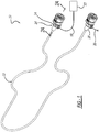
- the conduit assembly includes a tube 12 and at least one connector 14.
- a second connector 16 is illustrated.
- An electrical contact 18 is illustrated electrically coupled with the connector 14.
- the electrical contact 18 includes an end 26 that extends from a box 24 formed by the connector 14.
- the end 26 receives a lead wire 19.
- the end 21 of the lead wire 19 functionally fits and is retained in the box 24.
- the remainder of the electrical contact 18 has an arcuate body 28 positioned in the connector body 14.
- the electrical contact 18 is molded, clamped or connected or the like into the polymeric material of the connector 14, 16 or tube 12.
- a ground wire 20 similar in manufacture to the lead wire, can be electrically coupled with the second connector 14, 16 or tube 12 that includes an electrical contact 18 like that described above.
- the ground wire 20 is secured to end 26 of the electrical contact on the connector 14, 16 or tube 12 like the lead wire.
- the lead wire 19 and ground wire 20 are electrically coupled with electrical contacts 18 on the connector 14, 16 or tube 12.
- an electrical current source (such as a wire harness) 22 can be electrically coupled with the electrical contact 18 so that an electrical current can flow through the conduit assembly 10 to the ground wire 20. As this occurs, the electrical current heats the conduit assembly, like a filament, to a desired temperature.
- the connectors 14, 16 are mechanically connected with the tube 12.
- the connection of the tube 12 with the connectors 14, 16 enables the electrical current to pass directly between the connectors 14, 16 to the tube 12.
- the conduit assembly 10 acts as an electrical connection to enable electrical current to flow through the conduit assembly 10 to heat the conduit assembly 10 with the electric current.
- the tube 10 and connectors 14, 16 are formed or manufactured from the same or similar polymeric material.
- the polymeric material includes at least one polymer component, the at least polymer component having a modified backbone.
- the polymer component may include at least one of the following: polyester, polyols, copolyesters, polyacrylates, polysulfides, polyolfins, polyamines, polyurethane.
- a nanoparticulate component is incorporated into the backbone or a side chain present in the polymer component.
- the nanoparticulate component is of at least one inorganic functional nanoparticulate compound.
- the nanoparticulate component is present in an amount sufficient to provide an electrical conductivity ( ⁇ ) in a range between 1 x 10 -14 and 4.7 x 10 6 (S/m) at 20°C.
- the nano particles can be selected from the group consisting of iron, copper, lead, silver, nickel, cobalt, carbon graphite, manganese's and mixtures thereof.
- conduit assembly 10 an electric current is passed from the source 22 through the conduit assembly 10.
- the conduit assembly 10, with its electric contact 18 and ground wire 20, enables the electrical current to pass through the connectors 14, 16 and tube 10 manufactured from the polymeric material with a nanoparticulate component.
- the conduit assembly 10 is heated by the electrical current.
- This type of conduit assembly may be utilized in urea systems to thaw the urea during its use.
- urea systems are generally utilized in automobiles with diesel engines equipped with selective catalytic reduction exhaust treatment systems.
- a reducing agent such as urea or diesel exhaust is injected into the engine exhaust stream to cause a chemical reaction that converts the nitrogen oxide into nitrogen and water.
- a challenge encountered when using urea or the diesel exhaust fuel as a reducing agent is that it freezes at around -11°C and therefore it cannot be pumped through the tubes.
- conduit assembly could be utilized in any operation where a heated conduit is desired.
- Windshield washer lines, water lines, dispensing lines (such as soap) are types of line where heating is desirable.
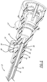
- FIG. 3 an additional embodiment is illustrated.
- the elements that are the same are identified with the same reference numerals.
- a second conduit assembly 10' includes a tube 12, at least one fluid connector 14 and a second fluid connector 16.
- a heating rod 30 passes through the conduit assembly 10'.
- the heating rod 30 is manufactured from the above described polymeric material.
- An electrical contact 18 is electrically coupled with one end of the heating rod 30.
- a ground 20 is coupled with the other end of the heating rod 30.
- Current is passed through the heating rod 30.
- the heating rod 30 is utilized as a filament, as explained above, to heat fluid in the conduit.
- the heating rod 30 can be solid or it can include a through bore. Additionally, the heating rod 30 could be removed from inside of the conduit and be wrapped around the outer circumference of the tube 12.
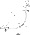
- FIG. 4 is an illustration like FIG. 1 .
- the conduit assembly 10 includes the electrical contact 18 in a self-standing box 24 connected directly to the tube 12.
- the ground 20 electrically couples with the tube 12.
- the voltage or current is passed through the tube 12 to heat the fluid as explained above.
- the fluid connectors if heated, would be heated by conductive heating by heat of the tube 12.
- the connectors 14, 16 need not be manufactured from the same material as the tube.
- the tube is manufactured from the material as described above.
- FIG. 5 illustrates an additional embodiment of the disclosure.
- the tube 12 is a multi-layer tube having five layers.
- the first layer 40 is manufactured from the material described above. This layer could be a mesh layer.
- the second layer 42 is non-conductive layer sandwiched between the first and third layers.
- the third layer 44 is a conductive layer like that described above and also could be a mesh layer.
- the fourth outer layer 46 is a non-conductive outer covering layer.
- the fifth layer 48 is a non-conductive inner layer.
- the connector 14' includes a pair of electrical contacts 18, 18'.
- the electrical contacts 18, 18' are attached to one or the other of the conductive first and third layers 40, 44.
- a lead line 19 can be connected to contact 18 and the ground 20 to the contact 18'.
- first and third layer 40,44 there is a similar connector attached to first and third layer 40,44.
- the electrical contacts 18, 18' are electrically connected to the first and third layers 40, 44 to route the current from contact 18, through layer 40, back through layer 44, to ground 18'.
- the current is also able to pass through the tube 12 to heat the tube which, in turn, heats fluid inside the tube.
- FIGS. 6-8 the embodiments are like those above. Accordingly, the same reference numerals have been utilized to identify similar or the same element. Thus, the full explanation of the element has been omitted.
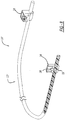
- a conduit is illustrated with a tube 12 with a pair of an electrical contacts 18.
- the electrical contacts include a contact end 26 that extends from a box 24.
- An arcuate body 28 extending from the end 26 and is positioned in the connector box peripherally about the tube 12.
- An electrical current source 22 is generally coupled with the electrical contact 18 so that current can flow through the tube 12 to the ground wire 20. As this occurs, electrical current is passed through the tube 12.
- a second tube 12 is illustrated.
- the contact includes a pair of electrical contacts 18, 18'.
- the pair of electrical contacts includes the arcuate members 28 sandwiched between the different layers as identified in FIG. 5 .
- the tube has two conductive layers 40, 44 with a non-conductive layer between the two.
- An outer layer 46 and inner layer 48 are also non-conductive layers.
- the electrical contacts 18, 18' can receive the live wire as well as the ground wire for passing the current through the tube.
- a jumper connection like that described above, is at the other end of the tube.
- FIG. 8 is similar to that of FIG. 6 .
- the tube 12" is solid. Accordingly, fluid does not pass through the tube.
- the tube 12" acts as a wire to enable current to pass through the tube 12".
- this plastic wire may be utilized in corrosive applications.
- a multilayer solid tube or wire may be utilized like that in FIG. 7 .
- the present disclosure may be utilized in electrostatic discharge applications in fuel lines.
- the movement of the fluid can, over time, lead to a buildup of electrostatic charge in nonconductive materials.
- the buildup can eventually lead to arcing between nearby components.
- This can lead to small holes in the conduit assembly enabling fluid to leak from the conduit.
- this type of leaking can be overcome.
- the tube can dissipate the electrostatic charge and avoid arcing.
- the present disclosure may be utilized in fluid conduit systems to dissipate electrostatic discharge.
Landscapes
- General Engineering & Computer Science (AREA)
- Engineering & Computer Science (AREA)
- Mechanical Engineering (AREA)
- Chemical & Material Sciences (AREA)
- Medicinal Chemistry (AREA)
- Chemical Kinetics & Catalysis (AREA)
- Health & Medical Sciences (AREA)
- Polymers & Plastics (AREA)
- Organic Chemistry (AREA)
- Rigid Pipes And Flexible Pipes (AREA)
- Pipe Accessories (AREA)
- Non-Insulated Conductors (AREA)
- Physical Or Chemical Processes And Apparatus (AREA)
- Resistance Heating (AREA)
- Insulated Conductors (AREA)
Applications Claiming Priority (2)
| Application Number | Priority Date | Filing Date | Title |
|---|---|---|---|
| US201662381862P | 2016-08-31 | 2016-08-31 | |
| US15/689,184 US10396500B2 (en) | 2016-08-31 | 2017-08-29 | Electrically conductive conduit assembly |
Publications (2)
| Publication Number | Publication Date |
|---|---|
| EP3302002A2 true EP3302002A2 (de) | 2018-04-04 |
| EP3302002A3 EP3302002A3 (de) | 2018-08-01 |
Family
ID=61240707
Family Applications (1)
| Application Number | Title | Priority Date | Filing Date |
|---|---|---|---|
| EP17188630.2A Withdrawn EP3302002A3 (de) | 2016-08-31 | 2017-08-30 | Elektrisch leitfähige leitungsanordnung |
Country Status (9)
| Country | Link |
|---|---|
| US (1) | US10396500B2 (de) |
| EP (1) | EP3302002A3 (de) |
| JP (1) | JP2018076961A (de) |
| KR (1) | KR20180025281A (de) |
| CN (1) | CN107801259A (de) |
| BR (1) | BR102017018787A2 (de) |
| CA (1) | CA2977928A1 (de) |
| MX (1) | MX2017011231A (de) |
| RU (1) | RU2017130850A (de) |
Families Citing this family (2)
| Publication number | Priority date | Publication date | Assignee | Title |
|---|---|---|---|---|
| CN110715120B (zh) * | 2019-08-29 | 2021-10-08 | 武汉船用机械有限责任公司 | 电液复合管 |
| EP4136387A1 (de) * | 2020-04-16 | 2023-02-22 | V-Zug AG | Gargerät |
Citations (1)
| Publication number | Priority date | Publication date | Assignee | Title |
|---|---|---|---|---|
| US9074053B2 (en) | 2013-03-15 | 2015-07-07 | Mackina Polymers, LLC | Polymeric composition with electroactive characteristics |
Family Cites Families (50)
| Publication number | Priority date | Publication date | Assignee | Title |
|---|---|---|---|---|
| US3580983A (en) | 1969-12-03 | 1971-05-25 | Nat Catheter Corp | Conductive line tube |
| US3914002A (en) | 1974-04-17 | 1975-10-21 | Sherwood Medical Ind Inc | Conductive tubing and method of making same |
| US3963856A (en) | 1974-11-25 | 1976-06-15 | Steward Plastics, Inc. | Flexible, corrugated, plastic tubing having conductive helical bead |
| DE4447330B4 (de) | 1994-12-31 | 2008-06-19 | Adolf Schnorr Gmbh & Co. Kg | Tellerfeder |
| US5791377A (en) * | 1996-07-08 | 1998-08-11 | Yazaki Corporation | Electrically heated conduit |
| DE10025707A1 (de) | 2000-05-26 | 2001-11-29 | Degussa | Mehrschichtiges, verstärktes Kunststoffanbindungselement mit antistatischen Eigenschaften |
| US20050271838A1 (en) | 2001-02-15 | 2005-12-08 | Integral Technologies, Inc. | Low cost vehicle fuel system components manufactured from conductive loaded resin-based materials |
| US6550815B2 (en) * | 2001-08-14 | 2003-04-22 | Itt Manufacturing Enterprises, Inc. | Coaxial quick connector |
| US20060061008A1 (en) * | 2004-09-14 | 2006-03-23 | Lee Karner | Mounting assembly for vehicle interior mirror |
| DE10326894B3 (de) | 2003-06-14 | 2004-09-30 | Rasmussen Gmbh | Heizvorrichtung mit einer elektrischen Wärmequelle zum Erwärmen eines Fluids in einer Fluidleitung eines Kraftfahrzeugs |
| US7445013B2 (en) | 2003-06-17 | 2008-11-04 | Whirlpool Corporation | Multiple wash zone dishwasher |
| US7123826B2 (en) | 2003-07-16 | 2006-10-17 | Wellstream International Ltd. | Temperature controlled pipe and method of manufacturing same |
| DE10338616A1 (de) | 2003-08-22 | 2005-03-24 | Hirschmann Electronics Gmbh & Co. Kg | Steckverbindung mit elektrisch leitfähiger Kunststoffklappe |
| DE10344137A1 (de) | 2003-09-24 | 2005-05-04 | Rasmussen Gmbh | Elektrisch beheizbare Flüssigkeitsleitung |
| DE502004005422D1 (de) | 2003-10-21 | 2007-12-20 | Norma Germany Gmbh | Fluidleitung |
| US20050186531A1 (en) | 2004-02-20 | 2005-08-25 | Joshua Friedman | Heated compule |
| US20060113696A1 (en) | 2004-07-12 | 2006-06-01 | Integral Technologies, Inc. | Low cost vehicle fuel system components manufactured from conductive loaded resin-based materials |
| DE102006051413B4 (de) | 2006-10-27 | 2009-01-02 | Norma Germany Gmbh | Elektrisch beheizbare Fluidleitung |
| EP2137449B2 (de) | 2007-04-26 | 2018-10-17 | Voss Automotive GmbH | Leitungsverbinder für medienleitungen |
| DE202007010502U1 (de) | 2007-07-26 | 2008-11-27 | Voss Automotive Gmbh | Konfektionierte Medienleitung |
| DE202007018089U1 (de) * | 2007-12-21 | 2009-05-07 | Voss Automotive Gmbh | Beheizbare Medienleitung |
| DE202008003908U1 (de) | 2008-03-19 | 2009-08-06 | Voss Automotive Gmbh | Beheizbare Fluidleitung mit einstellbarer Heizleistung |
| DE202008015289U1 (de) | 2008-11-18 | 2010-04-08 | Voss Automotive Gmbh | Leitungsverbinder für Medienleitungen |
| DE102008059751A1 (de) * | 2008-12-01 | 2010-06-02 | Voss Automotive Gmbh | Verfahren und Heizsystem zum Beheizen eines Fluid-Leitungssystems insbesondere in einem Kraftfahrzeug |
| US20100175469A1 (en) | 2009-01-09 | 2010-07-15 | Ni Frank Zhi | Electrically heated fluid tube |
| DE202009003807U1 (de) | 2009-03-20 | 2010-08-12 | Voss Automotive Gmbh | Elektrisches Heizsystem für ein Fluid-Leitungssystem |
| DE202009012230U1 (de) | 2009-06-23 | 2010-11-04 | Voss Automotive Gmbh | Elektrisch beheizbare Medienleitung sowie Leitungsverbinder |
| DE102010032188A1 (de) | 2010-07-23 | 2012-01-26 | Voss Automotive Gmbh | Beheizbare Medienleitung |
| DE102010032189B4 (de) | 2010-07-23 | 2024-07-25 | Voss Automotive Gmbh | Verfahren zum Herstellen einer beheizbaren Medienleitung und beheizbare Medienleitung, hergestellt nach dem Verfahren |
| DE102010051550A1 (de) | 2010-11-18 | 2012-05-24 | Voss Automotive Gmbh | Konfektionierte elektrisch beheizbare Medienleitung sowie Verfahren zum Herstellen einer solchen Medienleitung |
| JP5553032B2 (ja) | 2011-01-13 | 2014-07-16 | 日立金属株式会社 | ポジションセンサ用コード及びポジションセンサ並びに平面ポジションセンサ |
| DE102011018243A1 (de) | 2011-04-19 | 2012-10-25 | Voss Automotive Gmbh | Mehrlagige elektrisch beheizbare Medienleitung |
| DE102011017811A1 (de) | 2011-04-29 | 2012-10-31 | Evonik Degussa Gmbh | Temperierbare Rohrleitung für Offshoreanwendungen |
| DE102011075383A1 (de) | 2011-05-06 | 2012-11-08 | Evonik Degussa Gmbh | Temperierbare Rohrleitung für Offshoreanwendungen |
| DE102011102148A1 (de) | 2011-05-20 | 2012-11-22 | Norma Germany Gmbh | Fluidleitung |
| DE102011102244B4 (de) | 2011-05-20 | 2014-12-31 | Norma Germany Gmbh | Verbinder für eine beheizbare Fluidleitung und beheizbare Fluidleitung |
| CN103998845B (zh) | 2011-10-14 | 2017-11-03 | 福士汽车配套部件责任有限公司 | 用于可加热的介质管道的可至少部分加热的管道连接器和具有该管道连接器的组装介质管道 |
| DE202011106751U1 (de) | 2011-10-14 | 2013-01-18 | Voss Automotive Gmbh | Zumindest teilweise beheizbarer Leitungsverbinder für eine beheizbare Medienleitung sowie konfektionierte Medienleitung mit einem solchen Leitungsverbinder |
| DE102011120357A1 (de) | 2011-12-07 | 2013-06-13 | Voss Automotive Gmbh | Konfektionierte beheizbare Medienleitung mit einer Medienleitung mit zumindest zwei auf deren Außenseite angeordneten Heizelementen und Verfahren zu ihrer Herstellung |
| JP6131277B2 (ja) | 2012-02-28 | 2017-05-17 | ノーマ・ユー・エス・ホールディング・リミテッド・ライアビリティ・カンパニーNorma U. S. Holding Llc | 自動車選択的接触還元(scr)システムのセンサ保持部およびアセンブリ |
| CN103292629A (zh) | 2012-03-01 | 2013-09-11 | 欧司朗股份有限公司 | 热管及其制造方法 |
| DE102012208020A1 (de) | 2012-05-14 | 2013-11-14 | Evonik Industries Ag | Verfahren zur Herstellung eines beheizbaren Rohrs |
| US9765271B2 (en) * | 2012-06-27 | 2017-09-19 | James J. Myrick | Nanoparticles, compositions, manufacture and applications |
| EP2706280B1 (de) | 2012-09-10 | 2015-03-18 | NORMA Germany GmbH | Steckverbinder |
| DE102012020055A1 (de) | 2012-10-12 | 2014-04-17 | Voss Automotive Gmbh | Elektrisch beheizbare Medienleitung sowie Verfahren zum Herstellen einer solchen |
| DE102013000588A1 (de) | 2013-01-16 | 2014-07-17 | Voss Automotive Gmbh | Konfektionierte beheizbare Medienleitung, Verwendung einer solchen sowie Verfahren zum Herstellen einer solchen |
| CN105793703B (zh) | 2013-12-23 | 2019-10-18 | 安捷伦科技有限公司 | 用于从腔中移除电荷的esd保护管 |
| DE102014102353A1 (de) | 2014-02-24 | 2015-08-27 | Norma Germany Gmbh | Beheizbare Fluidleitung und Verbinder für eine beheizbare Fluidleitung |
| DE102014102357A1 (de) | 2014-02-24 | 2015-08-27 | Norma Germany Gmbh | Beheizbare Fluidleitung |
| DE102014102362A1 (de) | 2014-02-24 | 2015-08-27 | Norma Germany Gmbh | Verbinder für eine Fluidleitung |
-
2017
- 2017-08-29 US US15/689,184 patent/US10396500B2/en active Active
- 2017-08-30 JP JP2017165197A patent/JP2018076961A/ja active Pending
- 2017-08-30 EP EP17188630.2A patent/EP3302002A3/de not_active Withdrawn
- 2017-08-31 CN CN201710770805.8A patent/CN107801259A/zh active Pending
- 2017-08-31 BR BR102017018787-0A patent/BR102017018787A2/pt not_active IP Right Cessation
- 2017-08-31 RU RU2017130850A patent/RU2017130850A/ru not_active Application Discontinuation
- 2017-08-31 KR KR1020170110707A patent/KR20180025281A/ko not_active Withdrawn
- 2017-08-31 MX MX2017011231A patent/MX2017011231A/es unknown
- 2017-08-31 CA CA2977928A patent/CA2977928A1/en not_active Abandoned
Patent Citations (1)
| Publication number | Priority date | Publication date | Assignee | Title |
|---|---|---|---|---|
| US9074053B2 (en) | 2013-03-15 | 2015-07-07 | Mackina Polymers, LLC | Polymeric composition with electroactive characteristics |
Also Published As
| Publication number | Publication date |
|---|---|
| US10396500B2 (en) | 2019-08-27 |
| RU2017130850A (ru) | 2019-03-01 |
| CA2977928A1 (en) | 2018-02-28 |
| US20180062322A1 (en) | 2018-03-01 |
| KR20180025281A (ko) | 2018-03-08 |
| EP3302002A3 (de) | 2018-08-01 |
| CN107801259A (zh) | 2018-03-13 |
| MX2017011231A (es) | 2018-09-21 |
| JP2018076961A (ja) | 2018-05-17 |
| BR102017018787A2 (pt) | 2018-03-27 |
Similar Documents
| Publication | Publication Date | Title |
|---|---|---|
| US8526801B2 (en) | Line connector for media lines | |
| WO2012143121A1 (de) | Mehrlagige elektrisch beheizbare medienleitung | |
| CN103282712A (zh) | 可加热的流体导管、其应用以及其制造方法 | |
| CN105051440B (zh) | 预制可加热介质线、这种介质线的用途以及制造方法 | |
| CN100366974C (zh) | 管的连接结构 | |
| DE102010053736B4 (de) | Verbindungsanordnung für beheizbare Fluidleitungen | |
| US20100175469A1 (en) | Electrically heated fluid tube | |
| US10396500B2 (en) | Electrically conductive conduit assembly | |
| CN107101065B (zh) | 包括至少一个连接器和至少一个介质管路的连接器组件 | |
| JP2012059371A (ja) | 流体加熱用チューブ | |
| CN103261772B (zh) | 用于介质传导的可电加热软管的可加热连接装置 | |
| WO2009095941A1 (en) | Multilayer hose for conveying an aqueous solution containing urea | |
| US12135108B2 (en) | Electrostatic discharge mitigation tubing | |
| EP2619495B1 (de) | Leitungsystem für ein scr system in einem kraftfahrzeug | |
| DE102007027413B4 (de) | Reduktionsmittelversorgungssystem für einen Abgasreinigungskatalysator eines Verbrennungsmotors | |
| CN105934621A (zh) | 可加热空心体 | |
| DE102020200751A1 (de) | Gehäuseanordnung für vereisungsgefährdete Bauteilkomponenten oder Medien | |
| EP3172476B1 (de) | Beheizbarer schlauch | |
| US20170211740A1 (en) | Heatable Tube | |
| CN110073084A (zh) | 用于柴油机废气处理液贮存器的电气浸没式加热器 |
Legal Events
| Date | Code | Title | Description |
|---|---|---|---|
| PUAI | Public reference made under article 153(3) epc to a published international application that has entered the european phase |
Free format text: ORIGINAL CODE: 0009012 |
|
| STAA | Information on the status of an ep patent application or granted ep patent |
Free format text: STATUS: THE APPLICATION HAS BEEN PUBLISHED |
|
| AK | Designated contracting states |
Kind code of ref document: A2 Designated state(s): AL AT BE BG CH CY CZ DE DK EE ES FI FR GB GR HR HU IE IS IT LI LT LU LV MC MK MT NL NO PL PT RO RS SE SI SK SM TR |
|
| AX | Request for extension of the european patent |
Extension state: BA ME |
|
| PUAL | Search report despatched |
Free format text: ORIGINAL CODE: 0009013 |
|
| AK | Designated contracting states |
Kind code of ref document: A3 Designated state(s): AL AT BE BG CH CY CZ DE DK EE ES FI FR GB GR HR HU IE IS IT LI LT LU LV MC MK MT NL NO PL PT RO RS SE SI SK SM TR |
|
| AX | Request for extension of the european patent |
Extension state: BA ME |
|
| RIC1 | Information provided on ipc code assigned before grant |
Ipc: F16L 11/127 20060101ALI20180626BHEP Ipc: H05B 3/14 20060101ALI20180626BHEP Ipc: F16L 53/35 20180101ALI20180626BHEP Ipc: H05B 3/54 20060101AFI20180626BHEP |
|
| STAA | Information on the status of an ep patent application or granted ep patent |
Free format text: STATUS: REQUEST FOR EXAMINATION WAS MADE |
|
| 17P | Request for examination filed |
Effective date: 20190117 |
|
| RBV | Designated contracting states (corrected) |
Designated state(s): AL AT BE BG CH CY CZ DE DK EE ES FI FR GB GR HR HU IE IS IT LI LT LU LV MC MK MT NL NO PL PT RO RS SE SI SK SM TR |
|
| STAA | Information on the status of an ep patent application or granted ep patent |
Free format text: STATUS: THE APPLICATION IS DEEMED TO BE WITHDRAWN |
|
| 18D | Application deemed to be withdrawn |
Effective date: 20200303 |