EP3300870A1 - Method and device for producing a longitudinal slot element - Google Patents
Method and device for producing a longitudinal slot element Download PDFInfo
- Publication number
- EP3300870A1 EP3300870A1 EP17189871.1A EP17189871A EP3300870A1 EP 3300870 A1 EP3300870 A1 EP 3300870A1 EP 17189871 A EP17189871 A EP 17189871A EP 3300870 A1 EP3300870 A1 EP 3300870A1
- Authority
- EP
- European Patent Office
- Prior art keywords
- longitudinal
- concrete
- longitudinal beams
- mold
- beams
- Prior art date
- Legal status (The legal status is an assumption and is not a legal conclusion. Google has not performed a legal analysis and makes no representation as to the accuracy of the status listed.)
- Granted
Links
- 238000000034 method Methods 0.000 title claims description 41
- 238000004049 embossing Methods 0.000 claims abstract description 73
- 238000005266 casting Methods 0.000 claims abstract description 41
- 238000009826 distribution Methods 0.000 claims abstract description 5
- 238000007788 roughening Methods 0.000 claims description 5
- 230000000994 depressogenic effect Effects 0.000 claims description 4
- 238000004519 manufacturing process Methods 0.000 abstract description 11
- 238000005429 filling process Methods 0.000 abstract description 4
- JEIPFZHSYJVQDO-UHFFFAOYSA-N iron(III) oxide Inorganic materials O=[Fe]O[Fe]=O JEIPFZHSYJVQDO-UHFFFAOYSA-N 0.000 abstract description 2
- 241001465754 Metazoa Species 0.000 description 8
- 238000007373 indentation Methods 0.000 description 6
- 230000008901 benefit Effects 0.000 description 5
- 101100390736 Danio rerio fign gene Proteins 0.000 description 4
- 101100390738 Mus musculus Fign gene Proteins 0.000 description 4
- 238000010073 coating (rubber) Methods 0.000 description 4
- 238000005520 cutting process Methods 0.000 description 4
- 238000006073 displacement reaction Methods 0.000 description 4
- 238000003801 milling Methods 0.000 description 3
- 239000002689 soil Substances 0.000 description 3
- 239000006004 Quartz sand Substances 0.000 description 2
- 244000007853 Sarothamnus scoparius Species 0.000 description 2
- VYPSYNLAJGMNEJ-UHFFFAOYSA-N Silicium dioxide Chemical compound O=[Si]=O VYPSYNLAJGMNEJ-UHFFFAOYSA-N 0.000 description 2
- 230000006378 damage Effects 0.000 description 2
- 210000003608 fece Anatomy 0.000 description 2
- 239000000203 mixture Substances 0.000 description 2
- 229910000831 Steel Inorganic materials 0.000 description 1
- 208000027418 Wounds and injury Diseases 0.000 description 1
- 229910052782 aluminium Inorganic materials 0.000 description 1
- XAGFODPZIPBFFR-UHFFFAOYSA-N aluminium Chemical compound [Al] XAGFODPZIPBFFR-UHFFFAOYSA-N 0.000 description 1
- 238000013459 approach Methods 0.000 description 1
- 238000002788 crimping Methods 0.000 description 1
- 230000007423 decrease Effects 0.000 description 1
- 230000000694 effects Effects 0.000 description 1
- 238000002347 injection Methods 0.000 description 1
- 239000007924 injection Substances 0.000 description 1
- 208000014674 injury Diseases 0.000 description 1
- 239000000463 material Substances 0.000 description 1
- 229910052751 metal Inorganic materials 0.000 description 1
- 239000002184 metal Substances 0.000 description 1
- 229910001092 metal group alloy Inorganic materials 0.000 description 1
- 230000003278 mimic effect Effects 0.000 description 1
- 238000012544 monitoring process Methods 0.000 description 1
- 230000003534 oscillatory effect Effects 0.000 description 1
- 239000004033 plastic Substances 0.000 description 1
- 238000003825 pressing Methods 0.000 description 1
- 239000010959 steel Substances 0.000 description 1
- 230000007704 transition Effects 0.000 description 1
- 210000002700 urine Anatomy 0.000 description 1
Images


Classifications
-
- B—PERFORMING OPERATIONS; TRANSPORTING
- B28—WORKING CEMENT, CLAY, OR STONE
- B28B—SHAPING CLAY OR OTHER CERAMIC COMPOSITIONS; SHAPING SLAG; SHAPING MIXTURES CONTAINING CEMENTITIOUS MATERIAL, e.g. PLASTER
- B28B7/00—Moulds; Cores; Mandrels
- B28B7/16—Moulds for making shaped articles with cavities or holes open to the surface, e.g. with blind holes
- B28B7/18—Moulds for making shaped articles with cavities or holes open to the surface, e.g. with blind holes the holes passing completely through the article
- B28B7/186—Moulds for making shaped articles with cavities or holes open to the surface, e.g. with blind holes the holes passing completely through the article for plates, panels or similar sheet- or disc-shaped objects, also flat oblong moulded articles with lateral openings, e.g. panels with openings for doors or windows, grated girders
-
- A—HUMAN NECESSITIES
- A01—AGRICULTURE; FORESTRY; ANIMAL HUSBANDRY; HUNTING; TRAPPING; FISHING
- A01K—ANIMAL HUSBANDRY; CARE OF BIRDS, FISHES, INSECTS; FISHING; REARING OR BREEDING ANIMALS, NOT OTHERWISE PROVIDED FOR; NEW BREEDS OF ANIMALS
- A01K1/00—Housing animals; Equipment therefor
- A01K1/015—Floor coverings, e.g. bedding-down sheets ; Stable floors
- A01K1/0151—Grids; Gratings; Slatted floors
-
- B—PERFORMING OPERATIONS; TRANSPORTING
- B28—WORKING CEMENT, CLAY, OR STONE
- B28B—SHAPING CLAY OR OTHER CERAMIC COMPOSITIONS; SHAPING SLAG; SHAPING MIXTURES CONTAINING CEMENTITIOUS MATERIAL, e.g. PLASTER
- B28B7/00—Moulds; Cores; Mandrels
- B28B7/0064—Moulds characterised by special surfaces for producing a desired surface of a moulded article, e.g. profiled or polished moulding surfaces
- B28B7/0082—Moulds characterised by special surfaces for producing a desired surface of a moulded article, e.g. profiled or polished moulding surfaces with surfaces for moulding parallel grooves or ribs
Definitions
- the invention relates to Lekssspaltenrostiata for animal houses. Specifically, a method and an apparatus for producing such longitudinal cascade gratings made of concrete will be described.
- Prefabricated concrete longitudinal crevice gratings designed in an animal house (e.g., cowshed housing) for producing a floor are well known.
- Such Leksspaltenrostiata consist of two or more spaced-apart and arranged in a plane longitudinal beams and two or more spaced-apart and arranged in the plane of the longitudinal beams crossbar.
- a longitudinal gap is defined, which is intended for the disposal of animal faeces and veterinarians.
- Tierböden from prefabricated Leksspaltenrostmaschinen may, due to accumulated on the ground faeces and urine, become slippery. There is thus the risk that animals slip over the smooth surface of the ground and injure themselves when walking.
- the soil grip can be significantly improved.
- there are several approaches to applying surface structures For example, from the EP 1 563 728 B1 a method for the production of prefabricated longitudinal crevice gratings made of concrete for laying in an animal house known in which grooves are cut or milled on the surface of the longitudinal crevice grid elements. The cutting or milling process is carried out here after delimbing the L Lucassspaltenrostiata and partially cured concrete. The grooves thus produced extend in the longitudinal direction of the longitudinal beams and are rectangular in cross-section. The cutting of grooves can damage the concrete structure of the partially cured concrete, causing the mechanical strength of the grate elements decreases. Furthermore, sharp cutting or milling edges can arise, which can lead to injury to the animals.
- a method for the production of longitudinal crevice grating elements in which the surface of the longitudinal crevice grating elements is provided with a rubber coating.
- the rubber coating may in this case have a surface structure (such as surface grooves).
- the rubber coating is partially pressed into the fresh concrete during the production of the longitudinal ribbing elements.
- the attachment of the rubber elements requires a thorough monitoring of the manufacturing process. In particular, care must be taken that the concrete displaced when the rubber coating is pushed in can escape from the concrete casting mold.
- Object of the present invention is to provide a technically easy to implement and cost-effective technique for the production of Lekssspaltenrostmaschinen. It is a further object of the present invention to produce longitudinal splitting grids with improved surface properties and improved strength.
- a method for producing a concrete cascade comprising at least two longitudinal beams spaced apart and arranged in a plane and at least two transverse beams spaced apart and arranged in the plane of the longitudinal beams and crossing the at least two longitudinal beams , wherein in each case a longitudinal gap is defined by two adjacent longitudinal beams and two adjacent transverse beams.
- the indenting process can be mechanical or electromechanical.
- a pressure force can be applied to the at least one embossing element in such a way that the embossing element is pressed into the concrete on the exposed concrete surface.
- an oscillatory vibration movement can be exerted on the at least one embossing element. In this way, the at least one embossing element can be pressed particularly gently into the concrete.
- the exposed surface of the longitudinal crevice grid element can be further roughened in addition to the structuring described here by depressions.
- the method may include an additional process step of roughening the surface of the longitudinal crevice grid element.
- the process step of the roughening of the surface of the longitudinal column grid element can in this case a sprinkling of the surface with Include quartz sand or split.
- the step of roughening may include performing a brush stroke.
- brush stroke may be meant roughening of the surface in which a broom is pulled uniformly across the surface of the fresh concrete along a predetermined direction.
- the at least one embossing element can be configured and dimensioned such that it deforms (recesses) the surface of the Lekssspaltenrostelements only at the Eindschreibstellen during Eindschreibvorgang.
- surface areas of the longitudinal crevice grating element which surround the indentation points can remain unaffected by the indenting process. Thus, limited to the Eindschreibstellen local deformation (depression) is achieved.
- the at least one embossing element in the pushing-in direction and in a plane perpendicular to the pushing-in direction
- Displacement effects such as a bulging of the surface in the immediate vicinity of the wells due to concrete displacement during Eindgurvorgang are negligible. In particular, no provision must be made to drain the displaced amount of concrete from the molds.
- the step of creating a surface structure may further comprise aligning (orienting) the at least one embossing element with respect to the exposed surface of the longitudinal groove member.
- the alignment process may include aligning the at least one embossing element with respect to the longitudinal beams and / or transom. By the alignment process thus the orientation of the depressed recesses in the longitudinal beams and / or transom is determined.
- the at least one embossing element may be oriented such that each of the indented recesses is arranged parallel, perpendicular or at a predetermined angle to the longitudinal direction of the longitudinal beams (hereinafter longitudinal beam direction). It is also conceivable that the indented recesses in the longitudinal beam direction may have different orientations.
- the at least one embossing element may be formed such that the recess pressed in by the at least one embossing element forms a groove with a straight line or a groove is curved line shape.
- the groove may have a zig-zag line shape.
- each groove can have a triangular cross-section (triangular groove).
- the triangular groove may have a tip indented in the concrete which encloses an angle in the range between 45 ° and 90 °, preferably an angle of approximately 60 °.
- the surface structure may comprise at least two grooves per longitudinal beam, which are arranged spaced from each other. It is understood that instead of two grooves and three, four or more grooves per longitudinal beam can be realized.
- the at least two grooves can be generated by means of a single push-in step (ie simultaneously). Alternatively, it is also conceivable that the at least two grooves are generated sequentially, that is, by performing a plurality of successive following Eindschreib Kunststoffe.
- the step of releasing the longitudinal creel from the mold may comprise the substeps of: rotating the mold so that the exposed surface of the longitudinal creel with the indented surface features face down; and then de-scaling the longitudinal creel member downwardly from the mold.
- an apparatus for producing a concrete cascade comprising at least two longitudinal beams spaced from each other and arranged in one plane and at least two transverse beams arranged at a distance from one another in the plane of the longitudinal beams and crossing the at least two longitudinal beams adjacent longitudinal beams and two adjacent transverse beams each having a longitudinal gap defined
- said device comprising: a mold having the shape of the longitudinal column grid member corresponding, upwardly open casting spaces, which are intended to receive the concrete provided in a filling process; a vibrating table on which the mold is placed, the vibrating table being arranged to shake the mold during the filling operation to achieve a uniform concrete distribution in the casting spaces; and an indenting device having at least one embossing element, said embossing device being adapted to locally depress the at least one embossing element into the concrete of the longitudinal beams to create a surface structure on the exposed surface of the longitudinal beams.
- the at least one embossing element can be dimensioned so that it displaces a concrete volume during Eind Wegvorgang, which is negligible compared to the filled with concrete volume of the Lssensspaltenrostelements.
- the at least one embossing element may be rod-shaped with a predetermined length, width and depth dimensions.
- the at least one rod-shaped embossing element may have a triangular cross section or at least comprise a tip with a triangular cross section.
- the tip of the triangular embossing element may in this case form an angle in the range of 45 ° to 90 °, preferably an angle of approximately 60 °.
- the indenting device may have a single embossing element.
- the indenting device may have at least two spaced-apart embossing elements. In this way, at least two depressions (grooves) can be realized on the exposed surface of the longitudinal column grid element per indentation process.
- the push-in device may further comprise a pressure device, which is provided to pressurize the at least one embossing element with an (oscillating) pressure.
- the pressure to be applied can be preset or presettable.
- the push-in device may comprise an orientation device. This is intended to align the at least one embossing elements with respect to the Lekssspaltenrostelements.
- the device may further comprise a lifting device. This is coupled to the indenting device or coupled and provided to lower the indenting device during the Eind Wegvorgangs in the direction of the Lssensspaltenrostelements and to raise again after completion of the Eind Wegvorgangs.
- the device may further comprise a control device which is provided to control the indenting device and the lifting device in order to perform the indenting operation.
- the control device can be designed to control the orientation device of the push-in device for aligning the at least one embossing element.
- the control device may be provided for controlling the lifting device for lowering and / or raising the indenting device.
- the device may further comprise a tilting device, which is intended to rotate the mold after the surface structure has been produced, so that the exposed surface of the longitudinally spaced ribbed element with the pressed-in surface structure points downwards, and is subsequently detachable.
- a tilting device which is intended to rotate the mold after the surface structure has been produced, so that the exposed surface of the longitudinally spaced ribbed element with the pressed-in surface structure points downwards, and is subsequently detachable.
- a longitudinal cascade of concrete which can be produced by the method and apparatus described above.
- the Leksspaltenrostelement comprises at least two mutually spaced and arranged in a plane longitudinal beams and at least two spaced apart and arranged in the plane of the longitudinal beams and the at least two longitudinal beams crossing crossbar, wherein two adjacent longitudinal beams and two adjacent cross beams each have a longitudinal gap is defined, characterized in that at least the surface of the longitudinal slots has one or more recesses (grooves) each having a triangular cross-sectional profile.
- Each of the triangular depressions may have a tip pressed in the concrete, which has an angle in the range between 45 ° and 90 °, preferably an angle of approximately 60 °.
- the groove depth can be in the range between 2-20 mm, preferably in the range between 2-10 mm, more preferably in the range between 2-5 mm.
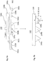
- Fig. 1 1 shows a schematic cross-section of the device 100.
- the device 100 comprises a vibrating table 110 with a vibrator motor 112, a casting mold 130 arranged on the vibrating table 110 with a plurality of casting spaces 132a, 132b, 132c and an injection device 160 arranged above the casting mold 130.
- the device 100 can optionally also include a support means 120 which is arranged between the vibrating table 110 and a bottom 136 of the mold 130 and is provided for supporting the mold 120. It is understood that according to an alternative variant, the device 100 can also rest directly on the vibrating table 110.
- the device 100 may include a lifting device coupled to the push-in device 160, which is provided for lowering and raising the push-in device 160.
- a lifting device coupled to the push-in device 160, which is provided for lowering and raising the push-in device 160.
- Fig. 1 only one part 170 of the lifting device is shown schematically.
- the lifting and lowering movement of the indenting device 160 is in Fig. 1 represented by the arrow 180.
- the casting spaces 132a, 132b, 132c of the casting mold 130 are designed to be open towards the top (ie, to the surface 134 of the casting mold 130). Thus, the casting spaces 132a, 132b, 132c can be filled from above with fresh concrete.
- the casting spaces 132a, 132b, 132c are constructed to correspond to the shape of the longitudinal creel member to be produced.
- Gussform 130 shown by way of example has three upwardly open casting spaces 132a, 132b, 132c with a trapezoidal cross section and is configured to form a longitudinal crevice grating element 140 with three longitudinal bars 142, 144, 146 arranged parallel to one another.
- Such a Leksspaltenrostelement 140 is in the FIGS. 5a-5e shown. It is understood that the number of casting spaces 132a, 132b, 132c and their shape depends on the shape of the longitudinal crevice grid element to be produced, and on that in the Fig. 1 may differ form shown. For example, the Lekspaltenrostelements 140 different from those in the FIGS. 5a-5e embodiments shown also have two longitudinal beams or four, five or more longitudinal beams. Accordingly, the mold 130 is equipped with two casting spaces or four, five or more casting spaces for forming longitudinal beams.
- the vibrating table 110 is configured to perform a shaking motion. This is transferred to the mold 130 carried by the vibrating table 110. By the shaking motion of the mold 130, the concrete filled in the casting spaces 132a, 132b, 132c is uniformly distributed and compacted in the casting spaces 132a, 132b, 132c.
- the longitudinal column grate element 140 is formed.
- the casting spaces 132a, 132b, 132c are filled to the top of the casting mold 134 with concrete.
- An exposed surface 147 of the longitudinal slot grid element 140 which can be patterned with the aid of the push-in device 160, thus arises on the casting mold top 134.
- the indenting device 160 provided for structuring the exposed surface 147 comprises at least one embossing element 162 and a bearing device 168 on which the at least one embossing element 162 is mounted.
- the indenter 160 is movable up and down with respect to the mold 130 mounted on the vibrating table 110 (see arrow 180) to create a surface structure on the exposed surface 147.
- the structuring of the exposed surface 147 by means of the indenting device 160 will be further described below.
- Fig. 2a shows a three-dimensional view of the in Fig. 1
- the indenting device 160 comprises a total of nine embossing elements 162a-c, 164a-c, 166a-c, wherein in each case three embossing elements are combined to form a group. Within each group are the embossing elements 162a-c. 164a-c, 166a-c are spaced from each other and arranged parallel to each other. Each triad is provided for the surface structuring of one of the three longitudinal beams 142, 144, 146.
- the grouped embossing elements 162a, 162b, 162c are in this case attached to three bearing elements 168a-c.
- three parallel recesses are pressed on the exposed surface 147 of each longitudinal bar 142, 144, 146.
- the indenter 160 per longitudinal beam 142, 144, 146 may also have fewer or more than three embossing elements.
- each of the embossing elements 162a-c, 164a-c, 166a-c is formed as a rectilinear rod with a triangular cross-sectional profile.
- the triangular bars are each coupled with a bar edge to the bearing elements 168a-c.
- the two remaining rod edges form a point that is pressed into the concrete, creating a groove with a triangular cross-section in the concrete.
- the embossing elements 162a-c, 164a-c, 166a-c may also differ from the configuration of a triangular bar described herein.
- each embossing element at its einzug Wegenden in the concrete section has a triangular cross-sectional profile for generating a triangular groove in the concrete.
- the length of the rod-shaped embossing elements 162a-c, 164a-c, 166a-c can be dimensioned differently depending on the type of surface structuring and the dimension of the longitudinal crevice grate element.
- the length of the rod-shaped embossing elements 162a-c, 164a-c, 166a-c substantially corresponds to the length of the longitudinal crevice grid element 140 to be structured.
- the embossing elements 162a-c, 164a-c, 166a-c may be made of metal (eg steel, Aluminum), a metal alloy, plastic or be formed from another material.
- the triangular cross-sectional profile of the embossing elements 162a-c, 164a-c, 166a-c is based on Fig. 2b further described.
- the embossing elements 162a-c, 164a-c, 166a-c have a downwardly pointing tip A, which is pressed into the concrete.
- a first cross-sectional side b and second cross-sectional side c forming the tip A are essentially of equal length and are inclined relative to each other such that they enclose an angle ⁇ at the tip A which lies in the range between 45 ° and 90 °.
- the cross-sectional side a acts as a bearing side, by means of which the embossing elements 162a-c, 164a-c, 166a-c are mechanically connected to the bearing elements 168a-c.
- the advantages of the triangular configuration of the embossing elements described here are based on FIGS. 4a and 4b further explained.
- the mold 130 is first provided and placed on the vibrating table 110 of the apparatus 100.
- the casting spaces 132a, 132b, 132c open at the upper side 134 of the casting mold 130 are filled with concrete.
- fresh concrete at the upper side 134 of the casting mold 130 is filled into the casting spaces 132a, 132b, 132c until the casting spaces 132a, 132b, 132c are filled with concrete up to the upper side 134 of the casting mold 130.
- the exposed concrete surface 147 of the L Lucassspaltentrostelements 140 thus arises at the top 134.
- the mold 130 is vibrated by means of the vibrating table 110 (step S30). In this way, the concrete in the casting spaces 132a, 132b, 132c is evenly distributed and compacted. After the casting spaces 132a, 132b, 132c are completely filled, the shaking operation is ended. If necessary, the concrete surface 147 exposed at the top 134 is further smoothed. In order to increase the grip of the concrete surface, in an optional process step, the concrete surface can be sprinkled with split or quartz sand or evenly roughened with the aid of a broom.
- the exposed concrete surface 147 is further structured by means of the indenting device 160.
- the indenting process is carried out as long as the concrete in the casting spaces 132a-132b, 132c is fresh (ie not yet partially hardened).
- the indenting device 160 is lowered in the direction of the surface 134 of the mold 130 or the exposed surface 147 until a lower edge of the bearing device 168 has reached a presettable height distance H1 to the top 134 of the mold or exposed surface 147 (see Fig. 4a ).
- the indentation process can be limited to certain surface areas.
- the peak depth t of the embossing elements 162a-c, 164a-c, 166a-c is chosen so that the embossing elements 162a-c, 164a-c, 166a-c during the crimping process grooves 142a-c, 144a-c. 146a-c with a given depth t1 and a given surface width a1 (see Fign 4b and 5a ).
- Typical indentation depths t1 are in the range of 2-15 mm, preferably in the range between 2 to 10 mm, more preferably in the range between 2-5 mm.
- Typical surface widths a1 of the grooves 142a-c, 144a-c. 146a-c are in the range between 3-10 mm, preferably in the range 3-6 mm (see Fig. 4b ).
- the indenting device 160 is raised again (eg to a predetermined height value H2), whereby the embossing elements 162a-c, 164a-c, 166a-c from the indented grooves 142a-c, 144a-c. 146a-c are removed.
- the embossing elements 162a-c, 164a-c, 166a-c By removing the embossing elements 162a-c, 164a-c, 166a-c, the three-channel grooves 142a-c, 144a-c pressed in the concrete remain.
- 146a-c which extend in the longitudinal direction of the longitudinal beams 142, 144, 146. These give the concrete surface 147 the desired rough surface characteristic for improving the grip (cf. FIGS. 4b .
- the method step of lifting the push-in device 160 can take place immediately after the push-in operation, ie, as long as the concrete is still fresh and not partially cured.
- a concrete or concrete mixture is used which retains its consistency when fresh.
- the indentation time can be limited to a few seconds to minutes.
- a final step S60 the shaped and surface-structured longitudinal crevice member 140 is released from the mold 130.
- the casting mold 130 is rotated by 180 ° with the aid of the tilting device, so that the exposed, structured surface 147 points downwards.
- the longitudinal crevice grating element 140 will be released from the mold 130 downwards (in FIG Fig. 1 not shown).
- the described triangular shape of the embossing elements 162a-c, 164a-c, 166a-c further enables a gentle embossing process.
- the triangular tips A penetrate gently into the fresh concrete and displace it gradually laterally outwards.
- the concrete along the angle ⁇ forming groove edges 141, 143 further compressed and thus strengthened (see. Fig. 4b ).
- the strength of the concrete surface and the quality of the grooves is thus further increased.
- the concrete structure is not damaged by the Eindschreibvorgang described, as is often the case, for example, when cutting or milling grooves.
- Another benefit of the triangular shape of the embossing elements 162a-c, 164a-c, 166a-c described herein is that at the location of the indented grooves 142a-c, 144a-c. 146a-c on the surface 147 no sharp edges arise.
- the obliquely downwardly tapered groove edges 141, 143 form with the horizontal surface 147 has an obtuse angle ⁇ , which exceeds 90 ° (see. Fig. 4b ). In this way, sharp transitions are avoided, which significantly increases the comfort for animals.
- a further benefit of the triangular shape of the embossing elements 162a-c, 164a-c, 166a-c and indented grooves 142a-c, 144a-c, 146a-c described herein is that the concrete surface is only locally modified by the imprinting process the triangular shape the displaced concrete volume is very small. Assuming that the indented grooves 142a-c, 144a-c.
- FIGS. 4a and 4b The advantages of the push - in technique described here are discussed in connection with FIGS. 5a-5e different embossing structures further discussed.
- FIGS. 5a and 5b is the Lekssspaltenrostelement 140 shown, as it can be realized for example with the Eindschreib worn 160 described.
- Fig. 5a shows a 3D view of the L Lucassspaltenrostelements 140
- Fig. 5b the longitudinal split grate element 140 is shown again in a plan view. It has three longitudinal beams 142, 144, 146 and three transverse beams 141, 143, 145.
- the longitudinal beams 142, 144, 146 have a surface structure 150 which comprises three rectilinear grooves 142a-c, 144a-c, 146a-c of each longitudinal beam 142, 144, 146 with a triangular cross-sectional profile.
- the grooves can be arranged perpendicular to the direction of the longitudinal beams 142, 144, 146.
- Such a surface structure 250 is shown in FIG Fig. 5c shown.
- the indented grooves may be obliquely aligned with respect to the longitudinal beam edges.
- a surface structure 350 is shown in which the indented grooves along the longitudinal beams 142, 144, 146 mimic a zig-zag line shape.
- a waveform is also conceivable.
- a surface structure 450 is shown in which domains of different groove orientation alternate along the longitudinal beams 142, 144, 146.
- the soil grip can be significantly improved.
- All of the surface structures 150, 250, 350, 450 described here have in common that the indented grooves have a triangular cross-sectional profile, as in connection with FIGS FIGS. 3 . 4a-4b has been described above. They differ only in the orientation (orientation) and length of the grooves. All of the surface structures 150, 250, 350, 450 described herein can be used with the in Fig. 1 shown device 100 can be realized. It is only necessary to adjust the alignment and length dimensions of the embossing elements of the surface structure to be realized.
Abstract
Es wird eine Vorrichtung und ein Verfahren zum Herstellen eines Längsspaltenrostelements aus Beton bereitgestellt, wobei das Längsspaltenrostelement wenigstens zwei voneinander beabstandete und in einer Ebene angeordnete Längsbalken und wenigsten zwei voneinander beabstandete und in der Ebene der Längsbalken angeordnete und die wenigstens zwei Längsbalken kreuzende Querbalken umfasst, wobei durch zwei benachbarte Längsbalken und zwei benachbarte Querbalken jeweils ein Längsspalt definiert ist. Das Herstellungsverfahren umfasst folgende Schritte: Bereitstellen einer Gussform auf einem Rütteltisch, wobei die Gussform nach oben offene Gussräume aufweist, welche die Form der Längsbalken und Querbalken vorgeben; Füllen der offenen Gussräume mit Beton zur Formung der Längsbalken und Querbalken; Rütteln der Gussform während des Füllvorgangs, um eine gleichförmige Betonverteilung in den Gussräumen zu erreichen; Erzeugen einer Oberflächenstruktur wenigstens entlang der Längsbalken, indem an der freiliegenden Oberfläche der Längsbalken wenigstens ein eine Oberflächenstruktur erzeugendes Prägeelement in den Beton der Längsbalken lokal eingedrückt wird; Entfernen des wenigstens einen in den Beton eingedrückten Prägeelements; und Lösen des so geformten Längsspaltenrostelements von der Gussform.There is provided an apparatus and a method for producing a concrete cascade, wherein the crosstie comprises at least two longitudinal beams spaced from each other and arranged in one plane and at least two transverse beams arranged at a distance from each other and arranged in the plane of the longitudinal beams and intersecting the at least two longitudinal beams is defined by two adjacent longitudinal beams and two adjacent cross beams each have a longitudinal gap. The manufacturing method comprises the following steps: providing a casting mold on a vibrating table, the casting mold having upwardly open casting spaces which predetermine the shape of the longitudinal beams and transverse bars; Filling the open casting rooms with concrete to form the longitudinal beams and crossbeams; Shaking the mold during the filling process to achieve a uniform concrete distribution in the casting spaces; Producing a surface structure at least along the longitudinal beams by locally impressing on the exposed surface of the longitudinal beams at least one embossing element which generates a surface structure in the concrete of the longitudinal beams; Removing the at least one embossed element pressed into the concrete; and releasing the thus formed longitudinal crevice rust element from the mold.
Description
Die Erfindung betrifft Längsspaltenrostelemente für Tierställe. Konkret wird ein Verfahren sowie eine Vorrichtung zur Herstellung derartiger Längsspaltenrostelemente aus Beton beschrieben.The invention relates to Längsspaltenrostelemente for animal houses. Specifically, a method and an apparatus for producing such longitudinal cascade gratings made of concrete will be described.
Vorgefertigte Längsspaltenrostelemente aus Beton, die in einem Tierstall (z.B. Stall für Kühe) zur Erzeugung eines Bodens ausgelegt werden, sind hinreichend bekannt. Derartige Längsspaltenrostelemente bestehen aus zwei oder mehreren voneinander beabstandeten und in einer Ebene angeordneten Längsbalken sowie zwei oder mehreren voneinander beabstandeten und in der Ebene der Längsbalken angeordneten Querbalken. Durch jeweils zwei benachbarte Längsbalken und Querbalken wird ein Längsspalt definiert, welcher zur Entsorgung von Tierkot und Tierurin vorgesehen ist. Tierböden aus vorgefertigten Längsspaltenrostelementen können, bedingt durch am Boden angesammelten Kot und Urin, glitschig werden. Es besteht somit die Gefahr, dass Tiere beim Gehen über die glatte Bodenoberfläche ausrutschen und sich verletzen.Prefabricated concrete longitudinal crevice gratings designed in an animal house (e.g., cowshed housing) for producing a floor are well known. Such Längsspaltenrostelemente consist of two or more spaced-apart and arranged in a plane longitudinal beams and two or more spaced-apart and arranged in the plane of the longitudinal beams crossbar. By two adjacent longitudinal beams and crossbars, a longitudinal gap is defined, which is intended for the disposal of animal faeces and veterinarians. Tierböden from prefabricated Längsspaltenrostelementen may, due to accumulated on the ground faeces and urine, become slippery. There is thus the risk that animals slip over the smooth surface of the ground and injure themselves when walking.
Durch Anbringen von Oberflächenstrukturen auf der Betonoberfläche der Längsspaltenrostelemente kann die Bodengriffigkeit erheblich verbessert werden. Hinsichtlich der Anbringung von Oberflächenstrukturen gibt es verschiedene Ansätze. So ist beispielsweise aus der
Aus der
Aufgabe der vorliegenden Erfindung ist es, eine technisch einfach zu realisierende und kostengünstige Technik zur Herstellung von Längsspaltenrostelementen bereitzustellen. Es ist ferner Aufgabe der vorliegenden Erfindung, Längsspaltenrostelemente mit verbesserten Oberflächeneigenschaften und verbesserter Festigkeit herzustellen.Object of the present invention is to provide a technically easy to implement and cost-effective technique for the production of Längsspaltenrostelementen. It is a further object of the present invention to produce longitudinal splitting grids with improved surface properties and improved strength.
Zur Lösung der Aufgaben wird gemäß einem ersten Aspekt ein Verfahren zum Herstellen eines Längsspaltenrostelements aus Beton bereitgestellt, das wenigstens zwei voneinander beabstandete und in einer Ebene angeordnete Längsbalken und wenigstens zwei voneinander beabstandete und in der Ebene der Längsbalken angeordnete und die wenigstens zwei Längsbalken kreuzende Querbalken umfasst, wobei durch zwei benachbarte Längsbalken und zwei benachbarte Querbalken jeweils ein Längsspalt definiert ist. Das Verfahren umfasst die folgenden Schritte: Bereitstellen einer Gussform auf einem Rütteltisch, wobei die Gussform nach oben offene Gussräume aufweist, welche die Form der Längsbalken und Querbalken vorgeben; Füllen der offenen Gussräume mit Beton zur Formung der Längsbalken und Querbalken; Rütteln der Gussform während des Füllvorgangs, um eine gleichförmige Betonverteilung in den Gussräumen zu erreichen; Erzeugen einer Oberflächenstruktur wenigstens entlang der Längsbalken, indem an der freiliegenden Oberfläche der Längsbalken wenigstens ein eine Oberflächenstruktur erzeugendes Prägeelement in den Beton der Längsbalken lokal eingedrückt wird; Entfernen des wenigstens einen in den Beton eingedrückten Prägeelements; und Lösen des so geformten Längsspaltenrostelements von der Gussform.In order to achieve the objects, according to a first aspect, there is provided a method for producing a concrete cascade comprising at least two longitudinal beams spaced apart and arranged in a plane and at least two transverse beams spaced apart and arranged in the plane of the longitudinal beams and crossing the at least two longitudinal beams , wherein in each case a longitudinal gap is defined by two adjacent longitudinal beams and two adjacent transverse beams. The method comprises the steps of: providing a mold on a vibrating table, the mold having upwardly open mold spaces defining the shape of the longitudinal beams and transoms; Filling the open casting rooms with concrete to form the longitudinal beams and crossbeams; Shaking the mold during the filling process to achieve a uniform concrete distribution in the casting spaces; Producing a surface structure at least along the longitudinal beams by locally impressing on the exposed surface of the longitudinal beams at least one embossing element which generates a surface structure in the concrete of the longitudinal beams; Removing the at least one in the concrete pressed-in embossing element; and releasing the thus formed longitudinal crevice rust element from the mold.
Durch das Eindrücken und Entfernen des wenigstens einen Prägeelements kann an der freiliegenden Betonoberfläche eine Oberflächenstruktur in Form lokaler Vertiefungen (wenigstens entlang der Längsbalken) realisiert werden. Auf diese Weise kann die Bodengriffigkeit verbessert werden. Zur Erzeugung der lokalen Vertiefungen kann das wenigstens eine Prägeelement nach Beendigung des Füll- und Rüttelvorgangs in den frischen Beton (kurz "Frischbeton") eingedrückt werden. Ferner kann das in den Beton eingedrückte wenigstens eine Prägeelement noch vor teilweiser Aushärtung des Frischbetons wieder entfernt werden. Die Eindrückzeit, d.h. die Zeitspanne, innerhalb der das wenigstens eine Prägeelement im Beton eingedrückt bleibt, kann auf eine kurze Zeitspanne begrenzt bleiben. Diese kann im Bereich von wenigen Sekunden bis mehreren Minuten liegen.By pressing in and removing the at least one embossing element, a surface structure in the form of local depressions (at least along the longitudinal bars) can be realized on the exposed concrete surface. In this way, the soil grip can be improved. To produce the local depressions, the at least one embossing element can be pressed into the fresh concrete ("fresh concrete" for short) after completion of the filling and shaking process. Furthermore, the pressed into the concrete at least one embossing element can still be removed before partial curing of the fresh concrete. The indentation time, i. the period of time during which the at least one embossing element remains pressed into the concrete can be limited to a short period of time. This can be in the range of a few seconds to several minutes.
Mit Frischbeton oder frischem Beton kann ein Beton im erdfeuchten Zustand gemeint sein. Damit frischer Beton nach Entfernen des wenigstens einen Prägeelements nicht in die eingedrückten Vertiefungen fließt und diese verschüttet, können Beton oder Betonmischung zum Einsatz kommen, die im erdfeuchten Zustand eine hohe Formstabilität aufweisen.With fresh concrete or fresh concrete, a concrete in the earth-moist state may be meant. So that fresh concrete does not flow into the indented recesses after removal of the at least one embossing element and spills it, concrete or concrete mixture can be used which have a high dimensional stability in the earth-moist state.
Mit freiliegender Oberfläche des Längsspaltenrostelements kann die in der Gussform von oben frei zugängliche Oberfläche des Längsspaltenrostelements gemeint sein.With exposed surface of the longitudinal column grid element may be meant in the mold from the top freely accessible surface of the Längsspaltenrostelements.
Der Eindrückvorgang kann mechanisch oder elektromechanisch erfolgen. Gemäß einer Variante kann am wenigstens einen Prägeelement eine Druckkraft derart angelegt werden, dass das Prägeelement an der freiliegenden Betonoberfläche in den Beton eingedrückt wird. Alternativ oder zusätzlich zur Druckkraft kann eine oszillatorische Vibrationsbewegung auf das wenigstens eine Prägeelement ausgeübt werden. Auf diese Weise kann das wenigstens eine Prägeelement besonders schonend in den Beton eingedrückt werden.The indenting process can be mechanical or electromechanical. According to a variant, a pressure force can be applied to the at least one embossing element in such a way that the embossing element is pressed into the concrete on the exposed concrete surface. Alternatively or in addition to the pressure force, an oscillatory vibration movement can be exerted on the at least one embossing element. In this way, the at least one embossing element can be pressed particularly gently into the concrete.
Die freiliegende Oberfläche des Längsspaltenrostelements kann zusätzlich zu der hier beschriebenen Strukturierung durch Eindrücken von Vertiefungen weiter aufgeraut werden. In diesem Fall kann das Verfahren einen zusätzlichen Verfahrensschritt zum Aufrauen der Oberfläche des Längsspaltenrostelements umfassen. Der Verfahrensschritt des Aufrauens der Oberfläche des Längsspaltenrostelements kann hierbei ein Einstreuen der Oberfläche mit Quarzsand oder Split umfassen. Alternativ kann der Verfahrensschritt des Aufrauens auch ein Durchführen eines Besenstrichs umfassen. Mit Besenstrich kann ein Aufrauen der Oberfläche gemeint sein, bei dem ein Besen entlang einer festgelegten Richtung gleichförmig über die Oberfläche des Frischbetons gezogen wird.The exposed surface of the longitudinal crevice grid element can be further roughened in addition to the structuring described here by depressions. In this case, the method may include an additional process step of roughening the surface of the longitudinal crevice grid element. The process step of the roughening of the surface of the longitudinal column grid element can in this case a sprinkling of the surface with Include quartz sand or split. Alternatively, the step of roughening may include performing a brush stroke. By brush stroke may be meant roughening of the surface in which a broom is pulled uniformly across the surface of the fresh concrete along a predetermined direction.
Das wenigstens eine Prägeelement kann derart ausgestaltet und dimensioniert sein, dass es beim Eindrückvorgang die Oberfläche des Längsspaltenrostelements lediglich an den Eindrückstellen verformt (vertieft). Hingegen können Oberflächenbereiche des Längsspaltenrostelements, welche die Eindrückstellen umgeben, durch den Eindrückvorgang unberührt bleiben. Somit wird eine auf die Eindrückstellen begrenzte, lokale Verformung (Vertiefung) erreicht.The at least one embossing element can be configured and dimensioned such that it deforms (recesses) the surface of the Längsspaltenrostelements only at the Eindrückstellen during Eindrückvorgang. On the other hand, surface areas of the longitudinal crevice grating element which surround the indentation points can remain unaffected by the indenting process. Thus, limited to the Eindrückstellen local deformation (depression) is achieved.
Ferner kann das wenigstens eine Prägeelement (in Eindrückrichtung und in einer Ebene senkrecht zur Eindrückrichtung) derart dimensioniert sein, dass es beim Eindrückvorgang ein Betonvolumen verdrängt, das im Vergleich zum Betonvolumen des Längsrostspaltelements vernachlässigbar ist. Verdrängungseffekte, wie beispielsweise ein Aufwölben der Oberfläche in unmittelbarer Umgebung der Vertiefungen bedingt durch Betonverdrängung beim Eindrückvorgang sind vernachlässigbar. Insbesondere müssen keine Vorkehrungen getroffen werden, um die verdrängte Betonmenge aus den Gussformen abfließen zu lassen.Furthermore, the at least one embossing element (in the pushing-in direction and in a plane perpendicular to the pushing-in direction) can be dimensioned such that it displaces a concrete volume during the pushing-in process, which is negligible in comparison to the concrete volume of the longitudinal-grid gap element. Displacement effects, such as a bulging of the surface in the immediate vicinity of the wells due to concrete displacement during Eindrückvorgang are negligible. In particular, no provision must be made to drain the displaced amount of concrete from the molds.
Der Schritt des Erzeugens einer Oberflächenstruktur kann ferner ein dem Eindrücken vorausgehendes Ausrichten (Orientieren) des wenigstens einen Prägeelements relativ zur freiliegenden Oberfläche des Längsspaltenrostelements umfassen. Der Ausrichtvorgang kann ein Ausrichten des wenigstens einen Prägeelements bezüglich der Längsbalken und/oder Querbalken umfassen. Durch den Ausrichtevorgang wird somit die Ausrichtung der eingedrückten Vertiefungen in den Längsbalken und/oder Querbalken festgelegt. Beispielsweise kann das wenigstens eine Prägeelement derart ausgerichtet sein, dass jede der eingedrückten Vertiefungen parallel, senkrecht oder in einem vorgegeben Winkel zur Längsrichtung der Längsbalken (im Folgenden Längsbalkenrichtung) angeordnet ist. Es ist auch denkbar, dass die eingedrückten Vertiefungen in Längsbalkenrichtung unterschiedliche Orientierungen aufweisen können.The step of creating a surface structure may further comprise aligning (orienting) the at least one embossing element with respect to the exposed surface of the longitudinal groove member. The alignment process may include aligning the at least one embossing element with respect to the longitudinal beams and / or transom. By the alignment process thus the orientation of the depressed recesses in the longitudinal beams and / or transom is determined. For example, the at least one embossing element may be oriented such that each of the indented recesses is arranged parallel, perpendicular or at a predetermined angle to the longitudinal direction of the longitudinal beams (hereinafter longitudinal beam direction). It is also conceivable that the indented recesses in the longitudinal beam direction may have different orientations.
Das wenigstens eine Prägeelement kann derart ausgebildet sein, dass die durch das wenigstens eine Prägeelement eingedrückte Vertiefung eine Rille mit geradliniger oder kurvenförmiger Linienform ist. Alternativ kann die Rille eine Zick-Zack-Linienform aufweisen. Unabhängig von der konkreten Linienform kann jede Rille einen dreieckförmigen Querschnitt aufweisen (dreikantige Rille). Die dreieckförmige Rille kann eine im Beton eingedrückte Spitze aufweisen, welche einen Winkel im Bereich zwischen 45° und 90°, vorzugsweise einen Winkel von ungefähr 60°, einschließt.The at least one embossing element may be formed such that the recess pressed in by the at least one embossing element forms a groove with a straight line or a groove is curved line shape. Alternatively, the groove may have a zig-zag line shape. Regardless of the concrete line shape, each groove can have a triangular cross-section (triangular groove). The triangular groove may have a tip indented in the concrete which encloses an angle in the range between 45 ° and 90 °, preferably an angle of approximately 60 °.
Gemäß einer Variante kann die Oberflächenstruktur wenigstens zwei Rillen pro Längsbalken aufweisen, welche voneinander beabstandet angeordnet sind. Es versteht sich, dass anstelle von zwei Rillen auch drei, vier oder mehr Rillen pro Längsbalken realisierbar sind. Die wenigstens zwei Rillen können mit Hilfe eines einzigen Eindrückschritts (also gleichzeitig) erzeugt werden. Alternativ ist auch vorstellbar, dass die wenigstens zwei Rillen sequentiell, also durch Durchführen mehrerer hintereinander folgender Eindrückschritte erzeugt werden.According to a variant, the surface structure may comprise at least two grooves per longitudinal beam, which are arranged spaced from each other. It is understood that instead of two grooves and three, four or more grooves per longitudinal beam can be realized. The at least two grooves can be generated by means of a single push-in step (ie simultaneously). Alternatively, it is also conceivable that the at least two grooves are generated sequentially, that is, by performing a plurality of successive following Eindrückschritte.
Der Schritt des Lösens des Längsspaltenrostelements von der Gussform kann folgende Unterschritte umfassen: Drehen der Gussform, so dass die freiliegende Oberfläche des Längsspaltenrostelements mit den eingedrückten Oberflächenstrukturen nach unten zeigt; und anschließendes Entschalen des Längsspaltenrostelements nach unten aus der Gussform.The step of releasing the longitudinal creel from the mold may comprise the substeps of: rotating the mold so that the exposed surface of the longitudinal creel with the indented surface features face down; and then de-scaling the longitudinal creel member downwardly from the mold.
Gemäß einem zweiten Aspekt wird eine Vorrichtung zur Herstellung eines Längsspaltenrostelements aus Beton bereitgestellt, das wenigstens zwei voneinander beabstandete und in einer Ebene angeordnete Längsbalken und wenigsten zwei voneinander beabstandete und in der Ebene der Längsbalken angeordnete und die wenigstens zwei Längsbalken kreuzende Querbalken umfasst, wobei durch zwei benachbarte Längsbalken und zwei benachbarte Querbalken jeweils ein Längsspalt definiert ist, wobei die Vorrichtung umfasst: eine Gussform mit der Form des Längsspaltenrostelements entsprechenden, nach oben offenen Gussräumen, welche dazu vorgesehen sind, den bei einem Füllvorgang bereitgestellten Beton aufzunehmen; einen Rütteltisch, auf den die Gussform aufgelegt ist, wobei der Rütteltisch dazu vorgesehen ist, die Gussform während des Füllvorgangs zu rütteln, um eine gleichförmige Betonverteilung in den Gussräumen zu erreichen; und eine Eindrückeinrichtung mit wenigstens einem Prägeelement, wobei die Eindrückeinrichtung dazu vorgesehen ist, das wenigstens eine Prägeelement in den Beton der Längsbalken lokal einzudrücken, um eine Oberflächenstruktur an der freiliegenden Oberfläche der Längsbalken zu erzeugen.According to a second aspect, there is provided an apparatus for producing a concrete cascade comprising at least two longitudinal beams spaced from each other and arranged in one plane and at least two transverse beams arranged at a distance from one another in the plane of the longitudinal beams and crossing the at least two longitudinal beams adjacent longitudinal beams and two adjacent transverse beams each having a longitudinal gap defined, said device comprising: a mold having the shape of the longitudinal column grid member corresponding, upwardly open casting spaces, which are intended to receive the concrete provided in a filling process; a vibrating table on which the mold is placed, the vibrating table being arranged to shake the mold during the filling operation to achieve a uniform concrete distribution in the casting spaces; and an indenting device having at least one embossing element, said embossing device being adapted to locally depress the at least one embossing element into the concrete of the longitudinal beams to create a surface structure on the exposed surface of the longitudinal beams.
Das wenigstens eine Prägeelement kann derart dimensioniert sein, dass es beim Eindrückvorgang ein Betonvolumen verdrängt, das im Vergleich zum mit Beton ausgefüllten Volumen des Längsspaltenrostelements vernachlässigbar ist. Das wenigstens eine Prägeelement kann stabförmig ausgebildet sein mit einer vorgegebenen Längen-, Breiten- und Tiefenabmessung. Das wenigstens eine stabförmige Prägeelement kann einen dreieckförmigen Querschnitt aufweisen oder wenigstens eine Spitze mit dreieckförmigen Querschnitt umfassen. Die Spitze des dreieckförmigen Prägeelements kann hierbei einen Winkel im Bereich von 45° bis 90°, vorzugsweise einen Winkel von ungefähr 60°, bilden.The at least one embossing element can be dimensioned so that it displaces a concrete volume during Eindrückvorgang, which is negligible compared to the filled with concrete volume of the Längsspaltenrostelements. The at least one embossing element may be rod-shaped with a predetermined length, width and depth dimensions. The at least one rod-shaped embossing element may have a triangular cross section or at least comprise a tip with a triangular cross section. The tip of the triangular embossing element may in this case form an angle in the range of 45 ° to 90 °, preferably an angle of approximately 60 °.
Gemäß einer Variante kann die Eindrückeinrichtung ein einziges Prägeelement aufweisen. Gemäß einer alternativen Variante kann die Eindrückeinrichtung wenigstens zwei voneinander beabstandet angeordnete Prägeelemente aufweisen. Auf diese Weise können pro Eindrückvorgang wenigstens zwei Vertiefungen (Rillen) an der freiliegenden Oberfläche des Längsspaltenrostelements realisiert werden.According to a variant, the indenting device may have a single embossing element. According to an alternative variant, the indenting device may have at least two spaced-apart embossing elements. In this way, at least two depressions (grooves) can be realized on the exposed surface of the longitudinal column grid element per indentation process.
Die Eindrückeinrichtung kann ferner eine Druckeinrichtung umfassen, welche dazu vorgesehen ist, das wenigstens eine Prägeelement mit einem (oszillierenden) Druck zu beaufschlagen. Der zu beaufschlagende Druck kann voreingestellt oder voreinstellbar sein.The push-in device may further comprise a pressure device, which is provided to pressurize the at least one embossing element with an (oscillating) pressure. The pressure to be applied can be preset or presettable.
Ferner kann die Eindrückeinrichtung eine Orientierungseinrichtung umfassen. Diese ist dazu vorgesehen, das wenigstens eine Prägeelemente bezüglich des Längsspaltenrostelements auszurichten.Furthermore, the push-in device may comprise an orientation device. This is intended to align the at least one embossing elements with respect to the Längsspaltenrostelements.
Die Vorrichtung kann ferner eine Hubeinrichtung umfassen. Diese ist mit der Eindrückeinrichtung gekoppelt oder koppelbar und dazu vorgesehen, die Eindrückeinrichtung während des Eindrückvorgangs in Richtung des Längsspaltenrostelements abzusenken und nach Beendigung des Eindrückvorgangs wieder anzuheben.The device may further comprise a lifting device. This is coupled to the indenting device or coupled and provided to lower the indenting device during the Eindrückvorgangs in the direction of the Längsspaltenrostelements and to raise again after completion of the Eindrückvorgangs.
Die Vorrichtung kann ferner eine Steuereinrichtung umfassen, welche dazu vorgesehen ist, die Eindrückeinrichtung und die Hubeinrichtung anzusteuern, um den Eindrückvorgang durchzuführen. Die Steuereinrichtung kann dazu ausgebildet sein, die Orientierungseinrichtung der Eindrückeinrichtung zur Ausrichtung des wenigstens einen Prägeelements anzusteuern. Ferner kann die Steuereinrichtung zur Ansteuerung der Hubeinrichtung zur Absenkung und/oder Anhebung der Eindrückeinrichtung vorgesehen sein.The device may further comprise a control device which is provided to control the indenting device and the lifting device in order to perform the indenting operation. The control device can be designed to control the orientation device of the push-in device for aligning the at least one embossing element. Furthermore, the control device may be provided for controlling the lifting device for lowering and / or raising the indenting device.
Die Vorrichtung kann ferner eine Kippeinrichtung umfassen, welche dazu vorgesehen ist, die Gussform nach Erzeugung der Oberflächenstruktur zu drehen, so dass die freiliegende Oberfläche des Längsspaltenrostelements mit der eingedrückten Oberflächenstruktur nach unten zeigt, und anschließend entschalbar ist.The device may further comprise a tilting device, which is intended to rotate the mold after the surface structure has been produced, so that the exposed surface of the longitudinally spaced ribbed element with the pressed-in surface structure points downwards, and is subsequently detachable.
Gemäß einem dritten Aspekt wird ein Längsspaltenrostelement aus Beton bereitgestellt, welches mittels dem oben beschriebenen Verfahren und Vorrichtung herstellbar ist. Das Längsspaltenrostelement umfasst wenigstens zwei voneinander beabstandete und in einer Ebene angeordnete Längsbalken und wenigsten zwei voneinander beabstandete und in der Ebene der Längsbalken angeordnete und die wenigstens zwei Längsbalken kreuzende Querbalken, wobei durch zwei benachbarte Längsbalken und zwei benachbarte Querbalken jeweils ein Längsspalt definiert ist, dadurch gekennzeichnet, dass wenigstens die Oberfläche der Längsspalten eine oder mehrere Vertiefungen (Rillen) aufweist, die jeweils ein dreieckförmiges Querschnittsprofil aufweisen.According to a third aspect, there is provided a longitudinal cascade of concrete which can be produced by the method and apparatus described above. The Längsspaltenrostelement comprises at least two mutually spaced and arranged in a plane longitudinal beams and at least two spaced apart and arranged in the plane of the longitudinal beams and the at least two longitudinal beams crossing crossbar, wherein two adjacent longitudinal beams and two adjacent cross beams each have a longitudinal gap is defined, characterized in that at least the surface of the longitudinal slots has one or more recesses (grooves) each having a triangular cross-sectional profile.
Jede der dreieckförmigen Vertiefungen kann eine im Beton eingedrückte Spitze aufweisen, welche einen Winkel im Bereich zwischen 45° und 90°, vorzugsweise einen Winkel von ungefähr 60°, aufweist. Die Rillentiefe kann im Bereich zwischen 2-20 mm, bevorzugt im Bereich zwischen 2-10 mm, noch bevorzugter im Bereich zwischen 2-5 mm liegen.Each of the triangular depressions may have a tip pressed in the concrete, which has an angle in the range between 45 ° and 90 °, preferably an angle of approximately 60 °. The groove depth can be in the range between 2-20 mm, preferably in the range between 2-10 mm, more preferably in the range between 2-5 mm.
Anhand von Zeichnungen werden Aspekte der vorliegenden Erfindung weiter erläutert. Es zeigen:
- Fig. 1
- eine schematische Darstellung einer Vorrichtung zur Herstellung eines Längsspaltenrostelements gemäß der vorliegenden Erfindung;
- Fign. 2a-2b
- schematische Darstellungen einer Eindrückkeinrichtung gemäß der vorliegenden Erfindung;
- Fig. 3
- ein Flussdiagramm eines Verfahrens zum Herstellen eines Längsspaltenrost-elements gemäß der vorliegenden Erfindung;
- Fign. 4a-4b
- eine schematische Darstellung des Eindrückvorgangs zur Strukturierung der Oberfläche eines Längsspaltenrostelements; und
- Fign. 5a-5e
- unterschiedliche Varianten von Oberflächenstrukturen, die gemäß dem erfindungsgemäßen Verfahren und Vorrichtung herstellbar sind.
- Fig. 1
- a schematic representation of an apparatus for producing a Längsspaltenrostelements according to the present invention;
- FIGS. 2a-2b
- schematic representations of a Eindrückkeinrichtung according to the present invention;
- Fig. 3
- a flowchart of a method for producing a longitudinal column grid element according to the present invention;
- FIGS. 4a-4b
- a schematic representation of the Eindrückvorgangs for structuring the surface of a Längsspaltenrostelements; and
- FIGS. 5a-5e
- different variants of surface structures that can be produced according to the method and apparatus according to the invention.
Anhand von
Die Gussräume 132a, 132b, 132c der Gussform 130 sind nach oben (also zur Oberfläche 134 der Gussform 130) hin offen ausgebildet. Somit können die Gussräume 132a, 132b, 132c von oben mit Frischbeton gefüllt werden. Die Gussräume 132a, 132b, 132c sind derart konstruiert, dass sie der Form des zu erzeugenden Längsspaltenrostelements entsprechen. Die in
Der Rütteltisch 110 ist dazu ausgebildet, eine Rüttelbewegung auszuführen. Diese wird auf die vom Rütteltisch 110 getragene Gussform 130 übertragen. Durch die Rüttelbewegung der Gussform 130 wird der in den Gussräumen 132a, 132b, 132c eingefüllte Beton in den Gussräumen 132a, 132b, 132c gleichmäßig verteilt und verdichtet.The vibrating table 110 is configured to perform a shaking motion. This is transferred to the
Durch Füllen der Gussräume 132a, 132b, 132c mit Beton wird das Längsspaltenrostelement 140 ausgebildet. Wie in
Die zur Strukturierung der freiliegenden Oberfläche 147 vorgesehene Eindrückeinrichtung 160 umfasst wenigstens ein Prägeelement 162 sowie eine Lagereinrichtung 168, an der das wenigstens ein Prägeelement 162 gelagert ist. Die Eindrückeinrichtung 160 ist bezüglich der auf dem Rütteltisch 110 gelagerten Gussform 130 nach unten und oben bewegbar (siehe Pfeil 180), um eine Oberflächenstruktur an der freiliegenden Oberfläche 147 zu erzeugen. Die Strukturierung der freiliegenden Oberfläche 147 mit Hilfe der Eindrückeinrichtung 160 wird nachfolgend weiter beschrieben.By filling the
The indenting
Anhand der
Wie ferner aus
Das dreieckförmige Querschnittprofil der Prägeelemente 162a-c, 164a-c, 166a-c wird anhand von
Im Zusammenhang mit der
In einem ersten Schritt wird zunächst die Gussform 130 bereitgestellt und auf dem Rütteltisch 110 der Vorrichtung 100 angeordnet.In a first step, the
In einem darauffolgenden zweiten Schritt S20 werden die an der Oberseite 134 der Gussform 130 offenen Gussräume 132a, 132b, 132c mit Beton gefüllt. Beim Füllvorgang wird Frischbeton an der Oberseite 134 der Gussform 130 solange in die Gussräume 132a, 132b, 132c eingefüllt, bis die Gussräume 132a, 132b, 132c bis zur Oberseite 134 der Gussform 130 mit Beton ausgefüllt sind. An der Oberseite 134 entsteht somit die freiliegende Betonoberfläche 147 des Längsspaltentrostelements 140.In a subsequent second step S20, the
Während des Füllens der offenen Gussräume 132a, 132b, 132c wird die Gussform 130 mit Hilfe des Rütteltisches 110 gerüttelt (Schritt S30). Auf diese Weise wird der Beton in den Gussräumen 132a, 132b, 132c gleichmäßig verteilt und verdichtet. Nachdem die Gussräume 132a, 132b, 132c vollständig ausgefüllt sind, wird der Rüttelvorgang beendet. Sofern erforderlich, wird die an der Oberseite 134 freiliegende Betonoberfläche 147 weiter glatt gestrichen. Um die Griffigkeit der Betonoberfläche zu erhöhen, kann in einem optionalen Verfahrensschritt die Betonoberfläche mit Split oder Quarzsand bestreut oder mit Hilfe eines Besens gleichmäßig aufgeraut werden.During the filling of the
Im anschließenden Schritt S40 wird die freiliegende Betonoberfläche 147 mit Hilfe der Eindrückeinrichtung 160 weiter strukturiert. Der Eindrückvorgang wird durchgeführt solange der Beton in den Gussräumen 132a- 132b, 132c frisch ist (also noch nicht teilweise ausgehärtet ist). Hierzu wird die Eindrückeinrichtung 160 in Richtung der Oberfläche 134 der Gussform 130 bzw. der freiliegenden Oberfläche 147 so weit abgesenkt, bis eine Unterkante der Lagereinrichtung 168 einen voreinstellbaren Höhenabstand H1 zur Oberseite 134 der Gussform bzw. freiliegenden Oberfläche 147 erreicht hat (siehe
Im darauffolgenden Schritt S50 wird die Eindrückeinrichtung 160 wieder angehoben (z.B. auf einen vorgegebenen Höhenwert H2), wodurch die Prägeelemente 162a-c, 164a-c, 166a-c aus den eingedrückten Rillen 142a-c, 144a-c. 146a-c entfernt werden. Durch Entfernen der Prägeelemente 162a-c, 164a-c, 166a-c bleiben die im Beton eingedrückten Dreikantrillen 142a-c, 144a-c. 146a-c zurück, welche sich in Längsrichtung der Längsbalken 142, 144, 146 erstrecken. Diese geben der Betonoberfläche 147 die gewünschte furchige Oberflächencharakteristik zur Verbesserung der Griffigkeit (vgl.
In einem abschließenden Schritt S60 wird das geformte und oberflächenstrukturierte Längsspaltenrostelement 140 von der Gussform 130 gelöst. Hierzu wird die Gussform 130 mit Hilfe der Kippeinrichtung um 180° gedreht, so dass die freiliegende, strukturierte Oberfläche 147 nach unten zeigt. Im Anschluss wird dann das Längsspaltenrostelement 140 aus der Gussform 130 nach unten entschalt werden (in
Die Vorteile der erfindungsgemäßen Eindrücktechnik wird anhand der
Wie in
Die beschriebene dreieckförmige Form der Prägeelemente 162a-c, 164a-c, 166a-c ermöglicht ferner einen schonenden Prägevorgang. Die dreieckförmigen Spitzen A dringen schonend in den Frischbeton ein und verdrängen diesen schrittweise lateral nach außen. Durch den sanften Verdrängungsvorgang wird der Beton entlang der den Winkel α bildenden Rillenkanten 141, 143 weiter verdichtet und somit gestärkt (vgl.
Ein weiterer Nutzen der hier beschriebenen dreieckförmigen Form der Prägeelemente 162a-c, 164a-c, 166a-c liegt darin, dass am Ort der eingedrückten Rillen 142a-c, 144a-c. 146a-c an der Oberfläche 147 keine spitze Kanten entstehen. Die schräg nach Unten zulaufenden Rillenkanten 141, 143 bilden mit der horizontalen Oberfläche 147 einen stumpfen Winkel β, welcher 90° überschreitet (vgl.
Ein weiterer Nutzen der hier beschriebenen dreieckförmigen Gestalt der Prägeelemente 162a-c, 164a-c, 166a-c und eingedrückten Rillen 142a-c, 144a-c, 146a-c besteht darin, dass durch den Eindruckvorgang die Betonoberfläche nur lokal modifiziert wird und durch die dreieckförmige Gestalt das verdrängte Betonvolumen sehr gering ist. Unter der Annahme, dass die eingedrückte Rillen 142a-c, 144a-c. 146a-c jeweils eine Tiefe von 3 mm, eine Breite von 4 mm an der Oberfläche sowie eine Länge von 1000 mm aufweist (was in etwa der Länge des Längsspaltenrostelement 140 entspricht), beträgt das durch eine Rille 142a-c, 144a-c, 146a-c verdrängte Betonvolumen in der Nähe der Oberfläche 147 des Längsspaltenrostelements 140 gemäß der Gleichung Vr = 1/2 · 3 mm · 4 mm · 1000 mm ungefähr 6000 mm3. Unter der weiteren Annahme, dass der Abstand jeder Rille 142a-c, 144a-c, 146a-c zu einer benachbarten Rille bzw. zu einer Kante des Längsspaltenrostelements 140 in etwa 40 mm beträgt und dass das durch eine jede Rille 142a-c, 144a-c, 146a-c verdrängte Volumen lokal an der Oberfläche in den benachbarten unstrukturierten Bereich gleichmäßig verdrängt wird, so gilt unter der Annahme einer gleichförmigen Verdrängung in einem benachbarten, quaderförmigen Bereich die Beziehung: 1000 mm · 40 mm · Δh = 6000 mm3. Daraus ergibt sich durch Auflösung der Gleichung eine Höhendifferenz Δh = 6000 : 40000 = 0,15 mm. Daraus folgt, dass die Zunahme der Höhe der Betonoberfläche 147 aufgrund des verdrängten Betonvolumens während des Eindrückvorgangs lediglich 150 µm beträgt, was zu vernachlässigen ist. Da das verdrängte Betonvolumen leicht durch die unmittelbare Oberflächenumgebung aufgenommen werden kann, ohne dass die Höhe des Längsspaltenrostelements 140 wesentlich zunimmt, müssen bei der Herstellung somit keine Vorkehrungen getroffen werden, um das verdrängte Betonvolumen aufzunehmen oder abfließen zu lassen.A further benefit of the triangular shape of the
Nachdem im Zusammenhang mit den
In den
Alternativ zu dem in den
Gemäß einer weiteren Ausführung können die eingedrückten Rillen in Bezug zu den Längsbalkenkanten schräg ausgerichtet sein. In
In
Allen hier beschriebenen Oberflächenstrukturen 150, 250, 350, 450 ist gemeinsam, dass die eingedrückten Rillen ein dreieckförmiges Querschnittsprofil aufweisen, wie in Zusammenhang mit den
Claims (20)
Priority Applications (4)
| Application Number | Priority Date | Filing Date | Title |
|---|---|---|---|
| SI201731017T SI3300870T1 (en) | 2016-09-07 | 2017-09-07 | Method and device for producing a longitudinal slot element |
| PL17189871T PL3300870T3 (en) | 2016-09-07 | 2017-09-07 | Method and device for producing a longitudinal slot element |
| HRP20220013TT HRP20220013T1 (en) | 2016-09-07 | 2017-09-07 | Method and device for producing a longitudinal slot element |
| RS20211579A RS62772B1 (en) | 2016-09-07 | 2017-09-07 | Method and device for producing a longitudinal slot element |
Applications Claiming Priority (1)
| Application Number | Priority Date | Filing Date | Title |
|---|---|---|---|
| DE102016116703.7A DE102016116703A1 (en) | 2016-09-07 | 2016-09-07 | Method and device for producing a longitudinal column grate element |
Publications (2)
| Publication Number | Publication Date |
|---|---|
| EP3300870A1 true EP3300870A1 (en) | 2018-04-04 |
| EP3300870B1 EP3300870B1 (en) | 2021-11-10 |
Family
ID=59846399
Family Applications (1)
| Application Number | Title | Priority Date | Filing Date |
|---|---|---|---|
| EP17189871.1A Active EP3300870B1 (en) | 2016-09-07 | 2017-09-07 | Method and device for producing a longitudinal slot element |
Country Status (7)
| Country | Link |
|---|---|
| EP (1) | EP3300870B1 (en) |
| DE (1) | DE102016116703A1 (en) |
| HR (1) | HRP20220013T1 (en) |
| HU (1) | HUE057918T2 (en) |
| PL (1) | PL3300870T3 (en) |
| RS (1) | RS62772B1 (en) |
| SI (1) | SI3300870T1 (en) |
Citations (4)
| Publication number | Priority date | Publication date | Assignee | Title |
|---|---|---|---|---|
| CH86139A (en) * | 1919-11-21 | 1920-08-02 | Hegi Emile | Stable. |
| CA2324134A1 (en) * | 2000-10-24 | 2002-04-24 | Syri-Con Corporation | Pre-cast concrete slat |
| EP1916080A2 (en) * | 2006-10-27 | 2008-04-30 | METTEN Stein + Design GmbH & Co. KG | Method for forming concrete stones and/or plates |
| JP2011037649A (en) * | 2009-08-07 | 2011-02-24 | Ueda Shokai:Kk | Concrete product for barn equipment, and method for producing the same |
Family Cites Families (4)
| Publication number | Priority date | Publication date | Assignee | Title |
|---|---|---|---|---|
| CA2225093A1 (en) | 1998-01-28 | 1999-07-28 | Bruno Dupuis | Improved concrete slat molding machine for making safer and easier to clean slats |
| DK200300090A (en) | 2003-01-24 | 2004-07-25 | Perstrup Beton Ind As | Process for manufacturing stable floor elements with elastic tread surface |
| EP1563728B1 (en) | 2004-02-13 | 2006-06-07 | VAN DER VELDEN BETON, naamloze vennootschap | Method for the realisation of concrete grids for stable floors for cattle and the like. |
| SI2138289T1 (en) | 2008-06-23 | 2011-08-31 | Rudolf Schwarz | Method for producing a longitudinally slotted grid element |
-
2016
- 2016-09-07 DE DE102016116703.7A patent/DE102016116703A1/en not_active Withdrawn
-
2017
- 2017-09-07 HR HRP20220013TT patent/HRP20220013T1/en unknown
- 2017-09-07 HU HUE17189871A patent/HUE057918T2/en unknown
- 2017-09-07 PL PL17189871T patent/PL3300870T3/en unknown
- 2017-09-07 SI SI201731017T patent/SI3300870T1/en unknown
- 2017-09-07 EP EP17189871.1A patent/EP3300870B1/en active Active
- 2017-09-07 RS RS20211579A patent/RS62772B1/en unknown
Patent Citations (4)
| Publication number | Priority date | Publication date | Assignee | Title |
|---|---|---|---|---|
| CH86139A (en) * | 1919-11-21 | 1920-08-02 | Hegi Emile | Stable. |
| CA2324134A1 (en) * | 2000-10-24 | 2002-04-24 | Syri-Con Corporation | Pre-cast concrete slat |
| EP1916080A2 (en) * | 2006-10-27 | 2008-04-30 | METTEN Stein + Design GmbH & Co. KG | Method for forming concrete stones and/or plates |
| JP2011037649A (en) * | 2009-08-07 | 2011-02-24 | Ueda Shokai:Kk | Concrete product for barn equipment, and method for producing the same |
Also Published As
| Publication number | Publication date |
|---|---|
| EP3300870B1 (en) | 2021-11-10 |
| DE102016116703A1 (en) | 2018-03-08 |
| HUE057918T2 (en) | 2022-06-28 |
| PL3300870T3 (en) | 2022-01-17 |
| SI3300870T1 (en) | 2022-01-31 |
| HRP20220013T1 (en) | 2022-04-01 |
| RS62772B1 (en) | 2022-01-31 |
Similar Documents
| Publication | Publication Date | Title |
|---|---|---|
| DE2416764C2 (en) | Method for producing a component and device for carrying out this method | |
| DE19507881B4 (en) | Method of supporting an object made by stereolithography or another rapid prototype manufacturing method | |
| DE2817110A1 (en) | METHOD AND DEVICE FOR PRODUCING PANELS O.AE. | |
| DE19538257A1 (en) | Stereo:lithographic prodn. of three dimensional object and easily detached support | |
| EP2118370A1 (en) | Concrete sleeper and method for producing the same | |
| DE4402281A1 (en) | Method of manufacturing Concrete paving blocks | |
| EP1349717B1 (en) | Method for producing purpose-made blocks, a device therefor and a purpose-made block | |
| EP2767373A1 (en) | Method for producing a multilayer, reinforced concrete element | |
| EP1605101A1 (en) | Process and apparatus for the fabrication of a multilayered concrete plate | |
| DE102006059205B4 (en) | Paving stone with natural stone look and device for its production | |
| EP1568455A2 (en) | Concrete paving stone and apparatus for producing such a stone | |
| EP3300870B1 (en) | Method and device for producing a longitudinal slot element | |
| EP3647010B1 (en) | Method for the production of a stall floor element | |
| DE102012112175B4 (en) | Method for the production of floors for animal stables and floor for animal stables | |
| DE102006028887A1 (en) | Method and form for producing floor slabs of cement-bonded material or concrete | |
| DE3730355A1 (en) | Process and device for producing bricks from concrete | |
| DE224096C (en) | ||
| DE4244333A1 (en) | Composite slab or panel with top layer of granite etc. | |
| DE102014007829A1 (en) | Method and device for creating a flat surface | |
| DE4409923A1 (en) | Process for the mfr. of columnar concrete blocks with profiled surfaces | |
| DE3049144C2 (en) | ||
| EP0322751B1 (en) | Apparatus to be incorporated in a formwork for concrete building elements | |
| DE957830C (en) | Method and device for dividing plastic masses z. B. lightweight concrete | |
| DE282599C (en) | ||
| AT101382B (en) | Artificial paving and method for its manufacture. |
Legal Events
| Date | Code | Title | Description |
|---|---|---|---|
| REG | Reference to a national code |
Ref country code: HR Ref legal event code: TUEP Ref document number: P20220013 Country of ref document: HR |
|
| PUAI | Public reference made under article 153(3) epc to a published international application that has entered the european phase |
Free format text: ORIGINAL CODE: 0009012 |
|
| STAA | Information on the status of an ep patent application or granted ep patent |
Free format text: STATUS: THE APPLICATION HAS BEEN PUBLISHED |
|
| AK | Designated contracting states |
Kind code of ref document: A1 Designated state(s): AL AT BE BG CH CY CZ DE DK EE ES FI FR GB GR HR HU IE IS IT LI LT LU LV MC MK MT NL NO PL PT RO RS SE SI SK SM TR |
|
| AX | Request for extension of the european patent |
Extension state: BA ME |
|
| STAA | Information on the status of an ep patent application or granted ep patent |
Free format text: STATUS: REQUEST FOR EXAMINATION WAS MADE |
|
| 17P | Request for examination filed |
Effective date: 20180516 |
|
| RBV | Designated contracting states (corrected) |
Designated state(s): AL AT BE BG CH CY CZ DE DK EE ES FI FR GB GR HR HU IE IS IT LI LT LU LV MC MK MT NL NO PL PT RO RS SE SI SK SM TR |
|
| GRAP | Despatch of communication of intention to grant a patent |
Free format text: ORIGINAL CODE: EPIDOSNIGR1 |
|
| STAA | Information on the status of an ep patent application or granted ep patent |
Free format text: STATUS: GRANT OF PATENT IS INTENDED |
|
| INTG | Intention to grant announced |
Effective date: 20210317 |
|
| GRAJ | Information related to disapproval of communication of intention to grant by the applicant or resumption of examination proceedings by the epo deleted |
Free format text: ORIGINAL CODE: EPIDOSDIGR1 |
|
| STAA | Information on the status of an ep patent application or granted ep patent |
Free format text: STATUS: REQUEST FOR EXAMINATION WAS MADE |
|
| INTC | Intention to grant announced (deleted) | ||
| GRAS | Grant fee paid |
Free format text: ORIGINAL CODE: EPIDOSNIGR3 |
|
| STAA | Information on the status of an ep patent application or granted ep patent |
Free format text: STATUS: GRANT OF PATENT IS INTENDED |
|
| GRAP | Despatch of communication of intention to grant a patent |
Free format text: ORIGINAL CODE: EPIDOSNIGR1 |
|
| INTG | Intention to grant announced |
Effective date: 20210902 |
|
| GRAA | (expected) grant |
Free format text: ORIGINAL CODE: 0009210 |
|
| STAA | Information on the status of an ep patent application or granted ep patent |
Free format text: STATUS: THE PATENT HAS BEEN GRANTED |
|
| AK | Designated contracting states |
Kind code of ref document: B1 Designated state(s): AL AT BE BG CH CY CZ DE DK EE ES FI FR GB GR HR HU IE IS IT LI LT LU LV MC MK MT NL NO PL PT RO RS SE SI SK SM TR |
|
| REG | Reference to a national code |
Ref country code: GB Ref legal event code: FG4D Free format text: NOT ENGLISH |
|
| REG | Reference to a national code |
Ref country code: AT Ref legal event code: REF Ref document number: 1445655 Country of ref document: AT Kind code of ref document: T Effective date: 20211115 Ref country code: CH Ref legal event code: EP |
|
| REG | Reference to a national code |
Ref country code: DE Ref legal event code: R096 Ref document number: 502017011955 Country of ref document: DE |
|
| REG | Reference to a national code |
Ref country code: IE Ref legal event code: FG4D Free format text: LANGUAGE OF EP DOCUMENT: GERMAN |
|
| REG | Reference to a national code |
Ref country code: RO Ref legal event code: EPE |
|
| REG | Reference to a national code |
Ref country code: LT Ref legal event code: MG9D |
|
| REG | Reference to a national code |
Ref country code: NL Ref legal event code: MP Effective date: 20211110 |
|
| REG | Reference to a national code |
Ref country code: HR Ref legal event code: T1PR Ref document number: P20220013 Country of ref document: HR |
|
| PG25 | Lapsed in a contracting state [announced via postgrant information from national office to epo] |
Ref country code: LT Free format text: LAPSE BECAUSE OF FAILURE TO SUBMIT A TRANSLATION OF THE DESCRIPTION OR TO PAY THE FEE WITHIN THE PRESCRIBED TIME-LIMIT Effective date: 20211110 Ref country code: FI Free format text: LAPSE BECAUSE OF FAILURE TO SUBMIT A TRANSLATION OF THE DESCRIPTION OR TO PAY THE FEE WITHIN THE PRESCRIBED TIME-LIMIT Effective date: 20211110 Ref country code: BG Free format text: LAPSE BECAUSE OF FAILURE TO SUBMIT A TRANSLATION OF THE DESCRIPTION OR TO PAY THE FEE WITHIN THE PRESCRIBED TIME-LIMIT Effective date: 20220210 |
|
| REG | Reference to a national code |
Ref country code: SK Ref legal event code: T3 Ref document number: E 39144 Country of ref document: SK |
|
| PG25 | Lapsed in a contracting state [announced via postgrant information from national office to epo] |
Ref country code: IS Free format text: LAPSE BECAUSE OF FAILURE TO SUBMIT A TRANSLATION OF THE DESCRIPTION OR TO PAY THE FEE WITHIN THE PRESCRIBED TIME-LIMIT Effective date: 20220310 Ref country code: SE Free format text: LAPSE BECAUSE OF FAILURE TO SUBMIT A TRANSLATION OF THE DESCRIPTION OR TO PAY THE FEE WITHIN THE PRESCRIBED TIME-LIMIT Effective date: 20211110 Ref country code: PT Free format text: LAPSE BECAUSE OF FAILURE TO SUBMIT A TRANSLATION OF THE DESCRIPTION OR TO PAY THE FEE WITHIN THE PRESCRIBED TIME-LIMIT Effective date: 20220310 Ref country code: NO Free format text: LAPSE BECAUSE OF FAILURE TO SUBMIT A TRANSLATION OF THE DESCRIPTION OR TO PAY THE FEE WITHIN THE PRESCRIBED TIME-LIMIT Effective date: 20220210 Ref country code: NL Free format text: LAPSE BECAUSE OF FAILURE TO SUBMIT A TRANSLATION OF THE DESCRIPTION OR TO PAY THE FEE WITHIN THE PRESCRIBED TIME-LIMIT Effective date: 20211110 Ref country code: LV Free format text: LAPSE BECAUSE OF FAILURE TO SUBMIT A TRANSLATION OF THE DESCRIPTION OR TO PAY THE FEE WITHIN THE PRESCRIBED TIME-LIMIT Effective date: 20211110 Ref country code: GR Free format text: LAPSE BECAUSE OF FAILURE TO SUBMIT A TRANSLATION OF THE DESCRIPTION OR TO PAY THE FEE WITHIN THE PRESCRIBED TIME-LIMIT Effective date: 20220211 Ref country code: ES Free format text: LAPSE BECAUSE OF FAILURE TO SUBMIT A TRANSLATION OF THE DESCRIPTION OR TO PAY THE FEE WITHIN THE PRESCRIBED TIME-LIMIT Effective date: 20211110 |
|
| REG | Reference to a national code |
Ref country code: HU Ref legal event code: AG4A Ref document number: E057918 Country of ref document: HU |
|
| PG25 | Lapsed in a contracting state [announced via postgrant information from national office to epo] |
Ref country code: SM Free format text: LAPSE BECAUSE OF FAILURE TO SUBMIT A TRANSLATION OF THE DESCRIPTION OR TO PAY THE FEE WITHIN THE PRESCRIBED TIME-LIMIT Effective date: 20211110 Ref country code: EE Free format text: LAPSE BECAUSE OF FAILURE TO SUBMIT A TRANSLATION OF THE DESCRIPTION OR TO PAY THE FEE WITHIN THE PRESCRIBED TIME-LIMIT Effective date: 20211110 Ref country code: DK Free format text: LAPSE BECAUSE OF FAILURE TO SUBMIT A TRANSLATION OF THE DESCRIPTION OR TO PAY THE FEE WITHIN THE PRESCRIBED TIME-LIMIT Effective date: 20211110 |
|
| REG | Reference to a national code |
Ref country code: DE Ref legal event code: R097 Ref document number: 502017011955 Country of ref document: DE |
|
| PLBE | No opposition filed within time limit |
Free format text: ORIGINAL CODE: 0009261 |
|
| REG | Reference to a national code |
Ref country code: HR Ref legal event code: ODRP Ref document number: P20220013 Country of ref document: HR Payment date: 20220826 Year of fee payment: 6 |
|
| STAA | Information on the status of an ep patent application or granted ep patent |
Free format text: STATUS: NO OPPOSITION FILED WITHIN TIME LIMIT |
|
| 26N | No opposition filed |
Effective date: 20220811 |
|
| PG25 | Lapsed in a contracting state [announced via postgrant information from national office to epo] |
Ref country code: AL Free format text: LAPSE BECAUSE OF FAILURE TO SUBMIT A TRANSLATION OF THE DESCRIPTION OR TO PAY THE FEE WITHIN THE PRESCRIBED TIME-LIMIT Effective date: 20211110 |
|
| PG25 | Lapsed in a contracting state [announced via postgrant information from national office to epo] |
Ref country code: RO Free format text: LAPSE BECAUSE OF NON-PAYMENT OF DUE FEES Effective date: 20211110 Ref country code: MC Free format text: LAPSE BECAUSE OF FAILURE TO SUBMIT A TRANSLATION OF THE DESCRIPTION OR TO PAY THE FEE WITHIN THE PRESCRIBED TIME-LIMIT Effective date: 20211110 |
|
| REG | Reference to a national code |
Ref country code: CH Ref legal event code: PL |
|
| GBPC | Gb: european patent ceased through non-payment of renewal fee |
Effective date: 20220907 |
|
| REG | Reference to a national code |
Ref country code: BE Ref legal event code: MM Effective date: 20220930 |
|
| PG25 | Lapsed in a contracting state [announced via postgrant information from national office to epo] |
Ref country code: RS Free format text: LAPSE BECAUSE OF NON-PAYMENT OF DUE FEES Effective date: 20220907 |
|
| PG25 | Lapsed in a contracting state [announced via postgrant information from national office to epo] |
Ref country code: LI Free format text: LAPSE BECAUSE OF NON-PAYMENT OF DUE FEES Effective date: 20220930 Ref country code: IE Free format text: LAPSE BECAUSE OF NON-PAYMENT OF DUE FEES Effective date: 20220907 Ref country code: FR Free format text: LAPSE BECAUSE OF NON-PAYMENT OF DUE FEES Effective date: 20220930 Ref country code: CH Free format text: LAPSE BECAUSE OF NON-PAYMENT OF DUE FEES Effective date: 20220930 |
|
| REG | Reference to a national code |
Ref country code: HR Ref legal event code: ODRP Ref document number: P20220013 Country of ref document: HR Payment date: 20230824 Year of fee payment: 7 |
|
| PG25 | Lapsed in a contracting state [announced via postgrant information from national office to epo] |
Ref country code: BE Free format text: LAPSE BECAUSE OF NON-PAYMENT OF DUE FEES Effective date: 20220930 |
|
| PG25 | Lapsed in a contracting state [announced via postgrant information from national office to epo] |
Ref country code: GB Free format text: LAPSE BECAUSE OF NON-PAYMENT OF DUE FEES Effective date: 20220907 |
|
| PGFP | Annual fee paid to national office [announced via postgrant information from national office to epo] |
Ref country code: LU Payment date: 20230920 Year of fee payment: 7 Ref country code: CZ Payment date: 20230823 Year of fee payment: 7 Ref country code: AT Payment date: 20230919 Year of fee payment: 7 |
|
| PGFP | Annual fee paid to national office [announced via postgrant information from national office to epo] |
Ref country code: SK Payment date: 20230822 Year of fee payment: 7 Ref country code: SI Payment date: 20230825 Year of fee payment: 7 Ref country code: HU Payment date: 20230829 Year of fee payment: 7 Ref country code: HR Payment date: 20230824 Year of fee payment: 7 Ref country code: DE Payment date: 20230822 Year of fee payment: 7 |
|
| PGFP | Annual fee paid to national office [announced via postgrant information from national office to epo] |
Ref country code: IT Payment date: 20230927 Year of fee payment: 7 |