EP3300828A1 - Dépôt de matière dirigé inversé grâce à une entrée d'énergie - Google Patents
Dépôt de matière dirigé inversé grâce à une entrée d'énergie Download PDFInfo
- Publication number
- EP3300828A1 EP3300828A1 EP17187191.6A EP17187191A EP3300828A1 EP 3300828 A1 EP3300828 A1 EP 3300828A1 EP 17187191 A EP17187191 A EP 17187191A EP 3300828 A1 EP3300828 A1 EP 3300828A1
- Authority
- EP
- European Patent Office
- Prior art keywords
- substrate
- molten pool
- component
- computing device
- stream
- Prior art date
- Legal status (The legal status is an assumption and is not a legal conclusion. Google has not performed a legal analysis and makes no representation as to the accuracy of the status listed.)
- Pending
Links
Images


Classifications
-
- B—PERFORMING OPERATIONS; TRANSPORTING
- B23—MACHINE TOOLS; METAL-WORKING NOT OTHERWISE PROVIDED FOR
- B23K—SOLDERING OR UNSOLDERING; WELDING; CLADDING OR PLATING BY SOLDERING OR WELDING; CUTTING BY APPLYING HEAT LOCALLY, e.g. FLAME CUTTING; WORKING BY LASER BEAM
- B23K26/00—Working by laser beam, e.g. welding, cutting or boring
- B23K26/34—Laser welding for purposes other than joining
- B23K26/342—Build-up welding
-
- B—PERFORMING OPERATIONS; TRANSPORTING
- B22—CASTING; POWDER METALLURGY
- B22F—WORKING METALLIC POWDER; MANUFACTURE OF ARTICLES FROM METALLIC POWDER; MAKING METALLIC POWDER; APPARATUS OR DEVICES SPECIALLY ADAPTED FOR METALLIC POWDER
- B22F10/00—Additive manufacturing of workpieces or articles from metallic powder
- B22F10/20—Direct sintering or melting
- B22F10/25—Direct deposition of metal particles, e.g. direct metal deposition [DMD] or laser engineered net shaping [LENS]
-
- B—PERFORMING OPERATIONS; TRANSPORTING
- B22—CASTING; POWDER METALLURGY
- B22F—WORKING METALLIC POWDER; MANUFACTURE OF ARTICLES FROM METALLIC POWDER; MAKING METALLIC POWDER; APPARATUS OR DEVICES SPECIALLY ADAPTED FOR METALLIC POWDER
- B22F10/00—Additive manufacturing of workpieces or articles from metallic powder
- B22F10/30—Process control
- B22F10/36—Process control of energy beam parameters
-
- B—PERFORMING OPERATIONS; TRANSPORTING
- B22—CASTING; POWDER METALLURGY
- B22F—WORKING METALLIC POWDER; MANUFACTURE OF ARTICLES FROM METALLIC POWDER; MAKING METALLIC POWDER; APPARATUS OR DEVICES SPECIALLY ADAPTED FOR METALLIC POWDER
- B22F12/00—Apparatus or devices specially adapted for additive manufacturing; Auxiliary means for additive manufacturing; Combinations of additive manufacturing apparatus or devices with other processing apparatus or devices
- B22F12/30—Platforms or substrates
- B22F12/33—Platforms or substrates translatory in the deposition plane
-
- B—PERFORMING OPERATIONS; TRANSPORTING
- B22—CASTING; POWDER METALLURGY
- B22F—WORKING METALLIC POWDER; MANUFACTURE OF ARTICLES FROM METALLIC POWDER; MAKING METALLIC POWDER; APPARATUS OR DEVICES SPECIALLY ADAPTED FOR METALLIC POWDER
- B22F12/00—Apparatus or devices specially adapted for additive manufacturing; Auxiliary means for additive manufacturing; Combinations of additive manufacturing apparatus or devices with other processing apparatus or devices
- B22F12/30—Platforms or substrates
- B22F12/37—Rotatable
-
- B—PERFORMING OPERATIONS; TRANSPORTING
- B22—CASTING; POWDER METALLURGY
- B22F—WORKING METALLIC POWDER; MANUFACTURE OF ARTICLES FROM METALLIC POWDER; MAKING METALLIC POWDER; APPARATUS OR DEVICES SPECIALLY ADAPTED FOR METALLIC POWDER
- B22F12/00—Apparatus or devices specially adapted for additive manufacturing; Auxiliary means for additive manufacturing; Combinations of additive manufacturing apparatus or devices with other processing apparatus or devices
- B22F12/90—Means for process control, e.g. cameras or sensors
-
- B—PERFORMING OPERATIONS; TRANSPORTING
- B23—MACHINE TOOLS; METAL-WORKING NOT OTHERWISE PROVIDED FOR
- B23K—SOLDERING OR UNSOLDERING; WELDING; CLADDING OR PLATING BY SOLDERING OR WELDING; CUTTING BY APPLYING HEAT LOCALLY, e.g. FLAME CUTTING; WORKING BY LASER BEAM
- B23K15/00—Electron-beam welding or cutting
- B23K15/002—Devices involving relative movement between electronbeam and workpiece
-
- B—PERFORMING OPERATIONS; TRANSPORTING
- B23—MACHINE TOOLS; METAL-WORKING NOT OTHERWISE PROVIDED FOR
- B23K—SOLDERING OR UNSOLDERING; WELDING; CLADDING OR PLATING BY SOLDERING OR WELDING; CUTTING BY APPLYING HEAT LOCALLY, e.g. FLAME CUTTING; WORKING BY LASER BEAM
- B23K15/00—Electron-beam welding or cutting
- B23K15/0046—Welding
- B23K15/0086—Welding welding for purposes other than joining, e.g. built-up welding
-
- B—PERFORMING OPERATIONS; TRANSPORTING
- B23—MACHINE TOOLS; METAL-WORKING NOT OTHERWISE PROVIDED FOR
- B23K—SOLDERING OR UNSOLDERING; WELDING; CLADDING OR PLATING BY SOLDERING OR WELDING; CUTTING BY APPLYING HEAT LOCALLY, e.g. FLAME CUTTING; WORKING BY LASER BEAM
- B23K26/00—Working by laser beam, e.g. welding, cutting or boring
- B23K26/02—Positioning or observing the workpiece, e.g. with respect to the point of impact; Aligning, aiming or focusing the laser beam
- B23K26/03—Observing, e.g. monitoring, the workpiece
- B23K26/032—Observing, e.g. monitoring, the workpiece using optical means
-
- B—PERFORMING OPERATIONS; TRANSPORTING
- B23—MACHINE TOOLS; METAL-WORKING NOT OTHERWISE PROVIDED FOR
- B23K—SOLDERING OR UNSOLDERING; WELDING; CLADDING OR PLATING BY SOLDERING OR WELDING; CUTTING BY APPLYING HEAT LOCALLY, e.g. FLAME CUTTING; WORKING BY LASER BEAM
- B23K26/00—Working by laser beam, e.g. welding, cutting or boring
- B23K26/08—Devices involving relative movement between laser beam and workpiece
-
- B—PERFORMING OPERATIONS; TRANSPORTING
- B23—MACHINE TOOLS; METAL-WORKING NOT OTHERWISE PROVIDED FOR
- B23K—SOLDERING OR UNSOLDERING; WELDING; CLADDING OR PLATING BY SOLDERING OR WELDING; CUTTING BY APPLYING HEAT LOCALLY, e.g. FLAME CUTTING; WORKING BY LASER BEAM
- B23K26/00—Working by laser beam, e.g. welding, cutting or boring
- B23K26/14—Working by laser beam, e.g. welding, cutting or boring using a fluid stream, e.g. a jet of gas, in conjunction with the laser beam; Nozzles therefor
- B23K26/144—Working by laser beam, e.g. welding, cutting or boring using a fluid stream, e.g. a jet of gas, in conjunction with the laser beam; Nozzles therefor the fluid stream containing particles, e.g. powder
-
- B—PERFORMING OPERATIONS; TRANSPORTING
- B33—ADDITIVE MANUFACTURING TECHNOLOGY
- B33Y—ADDITIVE MANUFACTURING, i.e. MANUFACTURING OF THREE-DIMENSIONAL [3-D] OBJECTS BY ADDITIVE DEPOSITION, ADDITIVE AGGLOMERATION OR ADDITIVE LAYERING, e.g. BY 3-D PRINTING, STEREOLITHOGRAPHY OR SELECTIVE LASER SINTERING
- B33Y10/00—Processes of additive manufacturing
-
- B—PERFORMING OPERATIONS; TRANSPORTING
- B33—ADDITIVE MANUFACTURING TECHNOLOGY
- B33Y—ADDITIVE MANUFACTURING, i.e. MANUFACTURING OF THREE-DIMENSIONAL [3-D] OBJECTS BY ADDITIVE DEPOSITION, ADDITIVE AGGLOMERATION OR ADDITIVE LAYERING, e.g. BY 3-D PRINTING, STEREOLITHOGRAPHY OR SELECTIVE LASER SINTERING
- B33Y30/00—Apparatus for additive manufacturing; Details thereof or accessories therefor
-
- F—MECHANICAL ENGINEERING; LIGHTING; HEATING; WEAPONS; BLASTING
- F01—MACHINES OR ENGINES IN GENERAL; ENGINE PLANTS IN GENERAL; STEAM ENGINES
- F01D—NON-POSITIVE DISPLACEMENT MACHINES OR ENGINES, e.g. STEAM TURBINES
- F01D5/00—Blades; Blade-carrying members; Heating, heat-insulating, cooling or antivibration means on the blades or the members
- F01D5/005—Repairing methods or devices
-
- B—PERFORMING OPERATIONS; TRANSPORTING
- B22—CASTING; POWDER METALLURGY
- B22F—WORKING METALLIC POWDER; MANUFACTURE OF ARTICLES FROM METALLIC POWDER; MAKING METALLIC POWDER; APPARATUS OR DEVICES SPECIALLY ADAPTED FOR METALLIC POWDER
- B22F10/00—Additive manufacturing of workpieces or articles from metallic powder
- B22F10/50—Treatment of workpieces or articles during build-up, e.g. treatments applied to fused layers during build-up
-
- B—PERFORMING OPERATIONS; TRANSPORTING
- B22—CASTING; POWDER METALLURGY
- B22F—WORKING METALLIC POWDER; MANUFACTURE OF ARTICLES FROM METALLIC POWDER; MAKING METALLIC POWDER; APPARATUS OR DEVICES SPECIALLY ADAPTED FOR METALLIC POWDER
- B22F10/00—Additive manufacturing of workpieces or articles from metallic powder
- B22F10/60—Treatment of workpieces or articles after build-up
- B22F10/66—Treatment of workpieces or articles after build-up by mechanical means
-
- B—PERFORMING OPERATIONS; TRANSPORTING
- B22—CASTING; POWDER METALLURGY
- B22F—WORKING METALLIC POWDER; MANUFACTURE OF ARTICLES FROM METALLIC POWDER; MAKING METALLIC POWDER; APPARATUS OR DEVICES SPECIALLY ADAPTED FOR METALLIC POWDER
- B22F12/00—Apparatus or devices specially adapted for additive manufacturing; Auxiliary means for additive manufacturing; Combinations of additive manufacturing apparatus or devices with other processing apparatus or devices
- B22F12/50—Means for feeding of material, e.g. heads
- B22F12/55—Two or more means for feeding material
-
- B—PERFORMING OPERATIONS; TRANSPORTING
- B22—CASTING; POWDER METALLURGY
- B22F—WORKING METALLIC POWDER; MANUFACTURE OF ARTICLES FROM METALLIC POWDER; MAKING METALLIC POWDER; APPARATUS OR DEVICES SPECIALLY ADAPTED FOR METALLIC POWDER
- B22F5/00—Manufacture of workpieces or articles from metallic powder characterised by the special shape of the product
- B22F5/009—Manufacture of workpieces or articles from metallic powder characterised by the special shape of the product of turbine components other than turbine blades
-
- B—PERFORMING OPERATIONS; TRANSPORTING
- B22—CASTING; POWDER METALLURGY
- B22F—WORKING METALLIC POWDER; MANUFACTURE OF ARTICLES FROM METALLIC POWDER; MAKING METALLIC POWDER; APPARATUS OR DEVICES SPECIALLY ADAPTED FOR METALLIC POWDER
- B22F5/00—Manufacture of workpieces or articles from metallic powder characterised by the special shape of the product
- B22F5/04—Manufacture of workpieces or articles from metallic powder characterised by the special shape of the product of turbine blades
-
- F—MECHANICAL ENGINEERING; LIGHTING; HEATING; WEAPONS; BLASTING
- F05—INDEXING SCHEMES RELATING TO ENGINES OR PUMPS IN VARIOUS SUBCLASSES OF CLASSES F01-F04
- F05D—INDEXING SCHEME FOR ASPECTS RELATING TO NON-POSITIVE-DISPLACEMENT MACHINES OR ENGINES, GAS-TURBINES OR JET-PROPULSION PLANTS
- F05D2230/00—Manufacture
- F05D2230/20—Manufacture essentially without removing material
- F05D2230/22—Manufacture essentially without removing material by sintering
-
- Y—GENERAL TAGGING OF NEW TECHNOLOGICAL DEVELOPMENTS; GENERAL TAGGING OF CROSS-SECTIONAL TECHNOLOGIES SPANNING OVER SEVERAL SECTIONS OF THE IPC; TECHNICAL SUBJECTS COVERED BY FORMER USPC CROSS-REFERENCE ART COLLECTIONS [XRACs] AND DIGESTS
- Y02—TECHNOLOGIES OR APPLICATIONS FOR MITIGATION OR ADAPTATION AGAINST CLIMATE CHANGE
- Y02P—CLIMATE CHANGE MITIGATION TECHNOLOGIES IN THE PRODUCTION OR PROCESSING OF GOODS
- Y02P10/00—Technologies related to metal processing
- Y02P10/25—Process efficiency
Definitions
- the present disclosure generally relates to technique for forming a component using directed energy deposition.
- Additive manufacturing for example, directed energy deposition techniques, may be used to fabricate a component having a predetermined three-dimensional structure, typically by depositing material layer-by-layer or volume-by-volume to form the structure, rather than by removing material from an existing component. Additive manufacturing may be advantageous in many situations, such as rapid prototyping, forming components with complex three-dimensional structures, or the like.
- a method comprising controlling, by a computing device, a material source to direct a stream of solid material to a molten pool in an upward direction defined with respect to gravity, wherein a substrate defines a surface having the molten pool, wherein the molten pool faces a downward direction defined with respect to gravity, wherein the material combines with the molten pool to form a deposited volume of a plurality of deposited volumes, and wherein the plurality of deposited volumes defines a component.
- the method may further comprise controlling, by the computing device, a build platform configured to hold the substrate, to orient the substrate to allow undeposited material from the stream of solid material to substantially fall away from the substrate in a downward direction defined with respect to gravity.
- the method may further comprise controlling, by the computing device, the build platform to move the substrate to cause undeposited material from the stream of solid material to substantially fall away from the substrate in the downward direction defined with respect to gravity.
- the method may further comprise controlling, by the computing device, based on a digital representation of the component, an energy source to direct an energy beam at the substrate to form the molten pool.
- the surface may comprise a chamber surface at which the molten pool is formed.
- the control of the energy source may comprise advancing the molten pool along a path on the surface.
- the control of the material source may comprise directing the stream of solid material to the advancing molten pool along the path to form the plurality of deposited volumes.
- the plurality of deposited volumes may define a chamber comprising the chamber surface.
- the chamber may be substantially free of undeposited material from the stream of solid material.
- the method may further comprise controlling, by the computing device, the material source and the energy source to define a build direction of the component in the downward direction.
- the method may further comprise controlling, by the computing device, an imaging device to image one or more of the substrate, the molten pool, and the stream of solid material.
- Computer-readable instructions executable by a computing device may be provided that cause the computer to perform the aforesaid method.
- the computer-readable instructions may be encoded on a computer-readable medium.
- a system comprising: a material source; a substrate having a molten pool on a surface of the substrate, wherein the molten pool faces a downward direction defined with respect to gravity; and a computing device; wherein the computing device is configured to: control the material source to direct a stream of solid material to the molten pool in an upward direction defined with respect to gravity, wherein the material combines with the molten pool to form a deposited volume of a plurality of deposited volumes, and wherein the plurality of deposited volumes defines a component.
- the system may further comprise a build platform configured to hold the substrate.
- the computing device may be further configured to control the build platform to orient the substrate to allow undeposited material from the stream of solid material to substantially fall away from the substrate in a direction defined with respect to gravity.
- the computing device may be further configured to control the build platform to move the substrate to cause undeposited material from the stream of solid material to substantially fall away from the substrate in the direction defined with respect to gravity.
- the system may further comprise an energy source.
- the computing device may be configured to control, based on a digital representation of the component, the energy source to direct an energy beam at the substrate to form the molten pool.
- the surface may comprise a chamber surface at which the molten pool is formed.
- the computing device may be configured to control the energy device to advance the molten pool along a path on the surface.
- the computing device may be configured to control the material source to direct the stream of solid material to the advancing molten pool along the path to form the plurality of deposited volumes.
- the plurality of deposited volumes may define a chamber comprising the chamber surface.
- the chamber may be substantially free of undeposited material from the stream of solid material.
- the computing device may be configured to control the material source and the energy source to define a build direction of the component in the downward direction.
- the system may further comprise an imaging device.
- the computing device may be configured to control the imaging device to image one or more of the substrate, the molten pool, and the stream of solid material.
- example techniques for directed energy deposition may include directing an energy beam at a region of a component to form an advancing molten pool and delivering material to the advancing molten pool, resulting in combining of the material and a substrate of the component by sintering or melting, to form a deposited volume of a plurality of deposited volumes.
- the plurality of deposited volumes may define the component, for example, a volume of the component defining a chamber.
- uncombined, unmelted, or otherwise undeposited material from the stream may accumulate within depressions, chambers, or voids on or within components fabricated by additive manufacturing as successive layers are deposited. If the accumulated material is not removed, the finished article may define chambers that include residual material. Such residual material may be undesirable, for example, because they may change the mass or the mass distribution of the component, may lead to unintended vibration frequencies during operation of the component, may block channels or openings, or may result in an audible sound such as rustling or rattling.
- an example system may use inverted directed energy deposition.
- the example system may include a computing device that controls a material source to direct a stream of solid material to a molten pool in an upward direction defined with respect to gravity.
- the material may substantially combine with the molten pool to form a deposited volume of a plurality of deposited volumes.
- the plurality of deposited volumes defines a component. Undeposited material from the stream of solid material may fall away from the substrate in a downward direction defined with respect to gravity, so that the undeposited material does not accumulate within a chamber defined by the plurality of deposited volumes.
- systems and techniques are provided to fabricate components defining chambers that may be substantially free of undeposited or residual material.
- a downward direction according to the disclosure may include any direction directly towards or inclined towards a gravitational force.
- a direct downward direction may be parallel to the direction of ambient gravity.
- An inclined downward direction may point along an inclined axis greater than about 1 degrees, or greater than about 30 degrees, or less than about 60 degrees, or less than about 90 degrees relative to the direction of ambient gravity.
- An upward direction may include a direction directly away from or against the gravitational force, or inclined away from or against ambient gravity.
- a direct upward direction may be antiparallel to the direction of ambient gravity.
- An inclined upward direction may point along an inclined axis greater than about 1 degrees, or greater than about 30 degrees, or less than about 60 degrees, or less than about 90 degrees relative to the direction against ambient gravity. In this way, as used here, downward and upward may be defined with respect to the direction of gravity.
- FIG. 1A is a conceptual and schematic block diagram illustrating an example system 10 for directed energy deposition of a component 12.
- Example system 10 includes a computing device 14, a directed energy deposition tool 16, a controller 20, a material source 22, an energy source 24, and an imaging device 26.
- Component 12 may include any structure which may be fabricated using directed energy deposition.
- component 12 may include a gas turbine engine component, such as, a turbine blade, a turbine vane, a shroud, a seal fin, a platform, an airfoil, or the like.
- component 12 may include structural features and geometry of any size, shape, or both.
- component 12 may include a metal or alloy substrate.
- component 12 may include one or more of nickel, cobalt, nickel alloys, cobalt alloys, superalloys, or their combinations.
- Component 12 may include single crystal or polycrystalline materials.
- component 12 may include magnesium based, nickel based, ferrous, and titanium alloys.
- An example of a single crystal nickel based alloy is CMSX-4.
- the alloys may include alloying additions including at least one of Mn, Mg, Cr, Si, Co, W, Ta, Al, Ti, Hf, Re, Mo, Ni, Fe, B, Nb, V, C, and Y.
- component 12 may include composite materials.
- component 12 defines a depression, aperture, or void (collectively, "chamber").
- the chamber may include channels, for example, cooling channels; apertures, for example, cooling holes or impingement apertures; voids for reducing weight; apertures that may be used to join component 12 to another component, for example, by filling with a joining or brazing composition or a mechanical fastener; or other voids or regions free of material.
- Computing device 14 may control system 10 for fabricating component 12.
- Computing device 14 may include any of a wide range of devices, including computer servers, desktop computers, notebook (i.e., laptop) computers, tablet computers, and the like.
- computing device 14 may include a processor.
- the processor may include one or more microprocessors, digital signal processors (DSP), application specific integrated circuits (ASIC), field programmable gate arrays (FPGA), or other digital logic circuitry.
- DSP digital signal processors
- ASIC application specific integrated circuits
- FPGA field programmable gate arrays
- Computing device 14 may be communicatively coupled to directed energy deposition tool 16 and configured to control directed energy deposition tool 16.
- computing device 14 may generate or store a digital representation 12a of component 12.
- digital representation 12a may include a digital representation of chamber 18a generally corresponding to chamber 18 of component 12.
- computing device 14 may control directed energy deposition tool 16 to fabricate component 12 based on digital representation 12a.
- directed energy deposition tool 16 may include a controller 20 for controlling one or more of material source 22, energy source 24, and imaging device 26.
- Computing device 14 may send control signals to controller 20 for controlling direct energy deposition tool 16.
- computing device 14 may send operational signals to and receive status signals from controller 20 to control and monitor the operation of directed energy deposition tool 16.
- computing device 14 may not control directed energy deposition tool 16, and controller 20 may be configured to receive signals indicative of digital representation 12a from computing device 14 and to control directed energy deposition tool 16 based on digital representation 12a to fabricate component 12.
- additive manufacturing tool 16 may not include controller 20, and, instead of controller 20, computing device 14 may control one or more of material source 22, energy source 24, imaging device 26, and build platform 15 according to examples described with reference to controller 20.
- system 10 may include a build platform 15 to hold component 12.
- Build platform 15 may include one or more of an adhesive layer, an adhesive surface or pad, a coating, build tape, platform tape, kapton tape, blue tape, hooks, straps, brackets, or other fasteners to hold component 12 substantially stationary relative to build platform 15.
- component 12 may be bonded to build platform 15 by a thin layer of fused or molten material adhering to a surface of build platform 15.
- build platform 15 continues to hold partially or completely fabricated component 12 in various configurations, including upwards, downwards, sideways, or any other orientation with respect to gravity, until component 12 is detached, for example, by physical, mechanical, or chemical separation from build platform 15.
- system 10 may not include build platform 15, and controller 20 may control the position and orientation of component 12, for example, by controlling an industrial robot, a movable platform, or a multi-axis stage supporting component 12.
- one or both of at least partially fabricated component 12 and part or whole of build platform 15 may be considered to form a substrate 13.
- directed energy deposition tool 16 may deposit material on substrate 13 to eventually fabricate component 12, for example, held on build platform 15.
- substrate 13 may include a base component on which component 12 is further formed. The base component may be formed of any material to which material may be added using directed energy deposition or material addition.
- substrate 13 may include a damaged component on which component 12 is fabricated as part of a repair region, repair volume, or repair structure.
- the base or damaged component may be fabricated using any suitable technique for manufacturing metal or alloy components.
- the base or damaged component may be fabricated using at least one of casting, molding, stamping, cutting, punching, milling, etching, welding, or other metal working techniques.
- the base or damaged component itself may be fabricated using directed energy deposition.
- example systems and techniques described herein may be used to repair damage to various gas turbine engine components, for example, by restoring damaged components so that they conform to predetermined specifications.
- controller 20 may control, based on digital representation 12a, energy source 24 to direct an energy beam 28 at substrate 13, for example, at a surface of substrate 13.
- Energy source 24 may include a power source such as a laser source or an electron beam source (not shown) and output the energy beam 28 directed at substrate 13.
- energy beam 28 may include a laser beam, a plasma, light, electromagnetic radiation, an electron beam, or another form of focused energy absorbable by the material of component 12, the material to be added to component 12, or both, and sufficiently strong to heat the material to sinter or melt.
- energy beam 28 may include both the laser beam and the electron beam.
- energy source 24 may include laser sources including a gas, solid-state, semiconductor, dye, or any other laser source that may be used for directed energy deposition.
- energy source 24 may include an electron beam that includes a beam of electrons controlled by electronic and magnetic fields.
- system 10 may at least partially or wholly be under a reduced pressure or a vacuum.
- Controller 20 may control the position and orientation of energy source 24 and energy beam 28, for example, by controlling an industrial robot or a movable platform supporting energy source 24, or by controlling an optical path of energy beam 28 by controlling optical media such as reflectors, refractors, filters, and the like.
- Controller 20 may control various parameters of energy source 24, including the instantaneous power, peak power or intensity, power pulsing, average beam power, a peak beam power density, a beam heat input, travel speed, wavelength, direction, and orientation.
- Energy beam 28 may be focused or directed by a focusing lens along or on a path.
- controller 20 may control energy source 24 to advance energy beam 28 along a path to form molten pool 30 on substrate 13.
- Energy beam 28 may interact with material of substrate 13, for example, by fusing, melting, sintering, or otherwise modifying the material of substrate 13 at a focal region of energy beam 28 to form a molten pool 30 at a surface of substrate 13.
- molten pool 30 is adjacent an existing surface of component 12.
- molten pool 30 is adjacent an initial surface, for example, a pilot surface or coating applied to build platform 15.
- controller 20 may control energy source 24 to emit a diffuse energy beam, or a patterned array of beams, for example, a light pattern.
- the focal region may change as component 12 is fabricated, for example, along regions or surfaces of partly fabricated component 12, based on digital representation 12a.
- controller 20 may cause directed energy deposition tool 16 to fabricate component 12 by forming molten pools at different build locations along a tool path, and depositing material into successive molten pools to form a plurality of deposited volumes.
- controller 20 may ultimately deposit material in molten pools along a predetermined build direction, for example downwards (for example, directly toward or inclined toward a gravitational force).
- controller 20 may separately control material source 22 and energy source 24, for example, by separately controlling energy source 24 to direct energy beam 28 along a series of build locations to define a series of molten pools 30 or advancing molten pool 30, at successive focal regions or build locations to fabricate component 12 based on digital representation 12a, and controlling material source 22 to direct stream 32 to deposit a layer or volume of material 34 at or within molten pool 30. Therefore, controller 20 may direct a build location or molten pool 30 along a two-dimensional or three-dimensional tool path to fabricate component 12 based on digital representation 12a.
- controller 20 may control material source 22 of directed energy deposition tool 16 to direct a stream 32 of solid material 34 at molten pool 30. Controller 20 may control the position and orientation of material source 2 and stream 32, for example, by controlling an industrial robot, a movable platform, or a multi-axis stage that supports material source 20.
- Stream 32 may include fluid, powder, wire, particles, suspension, material suspended in a carrier fluid, or any other form of material that is susceptible to energy beam 28 to be deposited on substrate 13.
- stream 32 may include solid material 34 in the form of ceramic or metallic powders.
- material stream 32 may include solid material 34 that includes nickel, iron, or titanium alloys and optionally one or more alloying additions including one or more of Mn, Mg, Cr, Si, Co, W, Ta, Al, Ti, Hf, Re, Mo, Ni, Fe, B, Nb, V, C, and Y.
- stream 32 may include solid material 34 that includes powders including one or more of polycrystalline nickel base superalloys or cobalt base superalloys, such as an alloy including NiCrAlY or CoNiCrAlY.
- solid material 34 delivered by material source 22 may include a composition substantially the same as (e.g., the same or nearly the same as) the composition of the material from which component 12 is formed. In other examples, solid material 34 delivered by material source 22 may include a composition different from the composition of the material from which component 12 is formed.
- Material source 22 may include one or more delivery ports or delivery nozzles through which solid material 34 exits material source 22. Controller 20 may control material source 22 to deliver solid material 34 in stream 32 to molten pool 30. For example, material source 22 may deliver powder in conical shaped stream through a powder delivery annulus of material source 22 directed towards molten pool 30. Controller 20 may control a material flux of the stream 32, or other operating parameters of stream 32, for example, a carrier gas flow rate. In some examples, material source 22 may include a plurality of nozzles such that a powder stream having a converging profile is delivered by material source 22. For example, each nozzle of the plurality of nozzles may be substantially directed towards a target delivery zone or molten pool 30.
- solid material 34 may be combined or otherwise incorporated into molten pool 30 to define a deposited volume.
- solid material 34 and molten pool 30 may solidify or otherwise change state into a deposited volume of a plurality of deposited volumes.
- controller 20 may control energy source 24 and material source 22 to deposit solid material 34 in a series of molten pools 34, based on digital representation 12a, to eventually deposit a plurality of deposited volumes that defines partly fabricated, and eventually, completely fabricated, component 12.
- controller 20 may control one or both of energy source 24 and material source 22 to define a build direction for component 12, for example, a build direction along the downward direction with respect to gravity, as shown in Figure 1A .
- the build direction may be a direction in which layers of deposited volumes are deposited by directed energy deposition tool 16 during the fabrication of component 12.
- While substantially all solid material 34 from stream 32 may be combined into molten pool 30, some of solid material 34 may not combine with molten pool 30. For example, there may be slight misalignment between the path of energy beam 28 and stream 32, or local thermal variations or static electricity or other phenomena may deflect some material from stream 32 away from molten pool 30.
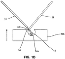
- Such undeposited material 34a may persist as residual material, for example, powder, dust, particles, agglomerates, or partly fused material, in a vicinity of molten pool 30, or otherwise on substrate 13. The presence of undeposited material 34a may be undesirable. For example, undeposited material 34a may block or otherwise prevent uniform creation of subsequent molten pools 30, leading to discontinuities or unacceptable disruptions in the structure of component 12.
- component 12 may include chamber 18, and undeposited material 34a may accumulate within chamber 18.
- Figure 1B is a conceptual and schematic block diagram illustrating accumulation of undeposited material 34a in a component 12b having a build direction along an upward direction defined with respect to gravity (see arrow). If solid material 34 is deposited in a downward direction (for example, in a direction directly or inclined toward gravitational forces), undeposited material 34a may accumulate on a surface of substrate 13, or eventually be incorporated within a bulk of substrate 13, or may accumulate within chamber 18, for example, as shown in Figure 1B .
- inverted directed energy deposition may be used, for example, as shown in Figure 1A .
- component 13 is above directed energy deposition tool 16, for example, with stream 32 directed upwards against gravitational force towards molten pool 30 on substrate 13, undeposited material 34 may fall away from substrate 13.
- undeposited material 34a may fall in a downward direction defined by gravitational force away from substrate 13, so that undeposited material 34a no longer accumulates at substrate 13.
- substrate 13 may be inverted so that molten pool 30 faces a downward direction defined with respect to gravity.
- Controller 20 may control material source 22 to direct stream 32 of solid material 34 to molten pool 30 in an upward direction defined with respect to gravity.
- Material for example, solid material 34, may combine with molten pool 30, for example, by melting or fusing into molten pool 30, to form a deposited volume of a plurality of deposited volumes.
- the plurality of deposited volumes defines partially fabricated, and eventually, completely fabricated, component 12.
- the plurality of deposited volumes may define a volume or region of component 12.
- the plurality of deposited volumes may define a surface of chamber 18.
- controller 12 may progressively fabricate component 12 in a downward build direction such that substantially no undeposited material 34a accumulates within component 12, for example, within chamber 18, as shown in FIGS. 2A-2C.
- Figure 2A is a conceptual cross-sectional diagram of an example substrate 13b including a partially fabricated component 12b defining a partially-fabricated chamber 18b.
- Example substrate 13b includes molten pool 30 at a surface of partially-fabricated chamber 18b.
- Figure 2B is a conceptual cross-sectional diagram of an example substrate 13c including a component 12c defining a partially-fabricated chamber 18c.
- Example substrate 13c includes molten pool 30 at a surface defining partially-fabricated chamber 18c.
- Figure 2C is a conceptual cross-sectional diagram of an example substrate 13d including a component 12d defining a chamber 18d. Chamber 18d is completely defined and substantially conforms to digital representation 18a. Chamber 18d is substantially free of undeposited material 34a.
- Example substrate 13c includes molten pool 30 at a surface of component 12d, that is in a downward direction relative to chamber 18d.
- build platform 15 may remain stationary as component 12 is fabricated.
- build platform 15 may be movable or rotatable, for example, along one or more axes, and controller 20 may control the position of build platform 15.
- controller 20 may successively move build platform 15 against the build direction, or to change the build location or location of molten pool 30 by changing the orientation of build platform 15, and that of component 12 or substrate 13, relative to stream 32 and energy beam 28.
- controller 20 may control imaging device 26 to image one or more of surfaces, regions, or volumes of component 12, substrate 13, build platform 15, molten pool 30, material 34, undeposited material 34a, or stream 32. Controller 20 may periodically or continuously compare the build images with digital representation 12a to verify that component 12 substantially conforms (e.g., conforms or nearly conforms) to digital representation 12a, during fabrication through completion. In some examples, controller 20 may control one or more of material source 22, energy source 24, and build platform 15 based on the build images and digital representation 12a. For example, controller 20 may be configured to control build platform 15 and material source 22, energy source 24, and/or imaging device 26 to translate and/or rotate along at least one axis to position component 12 relative to stream 32, energy beam 28, and/or imaging device 26.
- Positioning component 12 relative to stream 32, energy beam 28, and/or imaging 26 may include positioning a predetermined surface (e.g., a surface to which material is to be added) of component 12 in a predetermined orientation relative to material source 22, energy source 24, and/or imaging device 26, so that material is added in regions or volumes based on digital representation 12a.
- a predetermined surface e.g., a surface to which material is to be added
- system 10 may fabricate component 12 based on digital representation 12a using directed energy deposition
- system 10 may also fabricate component 12 by a combination of directed energy deposition and subtractive machining of component 12 or substrate 13.
- system 10 may optionally include machining tool 38 for one or more of milling, grinding, drilling, turning, burnishing, polishing, laser cutting, or otherwise machining component 12.
- portions of component 12 may be fabricated by machining tool 38, for example, based on digital representation 12a.
- controller 20 may control machining tool 38 before, during, or after directed energy deposition of one or more portions of component 12.
- controller 20 may control directed energy deposition tool 16 to fabricate a first volume of component 12.
- Controller 20 may compare the first volume of component 12 to the corresponding volume of digital representation 12a, for example, using images received from imaging device 26. In response to determining that portions of component 12 formed by directed energy deposition do not substantially conform to digital representation 12a, controller 20 may then control machining tool 38 to further machine component 12 based on digital representation 12a.
- controller 20 may control machining tool 38 to machine non-conforming portions of component 12 formed by directed energy deposition
- controller 20 may first control machining tool 38 to fabricate a first portion of component 12 using machining, and subsequently control direct energy deposition tool 16 to fabricate a second portion of component 12 on the machined first portion.
- controller 20 may control machining tool 38 to machine a portion of component 12 to define a first chamber surface.
- Controller 20 may then control directed energy deposition tool 16 to subsequently form plurality of deposited volumes on the first chamber surface, to define the ultimate geometry of a chamber surface, for example, a surface of chamber 18.
- controller 20 may use one or both of machining tool 38 and directed energy deposition tool 16 at different stages of fabricating component 12.
- debris, dust, or machined material generated by machining of component 12 or substrate 13 by machining tool 38 may fall away from substrate 13 in a downward direction.
- one or both of machined material and undeposited material 34a may fall away from substrate 13 to prevent the accumulation of one or both of machine material and undeposited material 34a within component 12 or substrate 13.
- controller 20 may control build platform 15 to orient substrate 13 to allow undeposited material 34a from stream 32 to substantially fall away from substrate 13 in a direction defined with respect to gravity (for example, in the direction of the arrow in Figure 1A ).
- controller 20 may control build platform 15 to orient (or reorient) substrate 13 such that substantially all of undeposited material 34a is unencumbered by any portion of substrate 13, and is free to fall away from substrate 13.
- substrate 13 may be orientated such that partly fabricated component 12 defining partial chamber 18 has an opening that faces downward or inclined downwards such that substantially all of undeposited material 34a within partial chamber 18 departs or falls away from chamber 18 towards gravitational forces. Thus, chamber 18 eventually will be substantially free of undeposited material 34a.
- controller 20 may control build platform 15 to move substrate 13 to cause undeposited material 34a from stream 32 to substantially fall away from substrate 13 in a direction defined with respect to gravity.
- controller 20 may control build platform 15 to shake, vibrate, spin, rotate, or otherwise move substrate 13 to propel or otherwise force undeposited material 34a away from substrate 13, for example, in a downward direction.
- controller 20 may control directed energy deposition tool 16 or other components to cause one or more of substrate 13, energy beam 28, and stream 32 to move or reorient relative to one another.
- controller 20 may simultaneously control build platform 15 to cause substrate 13 to move and control one or both of material source 22 and energy source 24 to respectively cause one or both of stream 32 and energy beam 28 to move or reorient relative to the substrate.
- example system 10 described above may be used to fabricate a component using inverted directed energy deposition, such that the component is substantially free of undeposited material.
- the component may define a chamber that is substantially free of undeposited material.
- the chamber may include channels, for example, cooling channels, apertures, for example, cooling holes or impingement apertures, voids for reducing weight, apertures that may be used to join component 12 to another component, for example, by filling with a joining or brazing composition, or other voids or regions free of material.
- the chamber may have a predetermined cross-section, for example, a curved, a polygonal, or a piecewise curved or polygonal cross-section.
- System 10 may be used to fabricate components, for example, using example techniques described with reference to Figure 3 . However, system 10 may be used to implement other suitable example techniques according to the disclosure.
- Figure 3 is a flow diagram illustrating an example technique for directed energy deposition of a component.
- the example technique of Figure 3 may partly or wholly be performed by example system 10 of Figure 1A , and is described in some examples below with reference to example system 10. However, in some examples, one or more steps of the example technique of Figure 3 may be performed by other example systems.
- the example technique of Figure 3 may include controlling, by computing device 14, based on digital representation 12a, directed energy deposition tool 16 to direct energy source 24 to form molten pool 30 and direct material 34 to molten pool 30, to fabricate component 12.
- the example technique of Figure 3 may include, controlling, by computing device 14, based on digital representation 12a of component 12, energy source 24 to direct energy beam 28 at substrate 13 to form molten pool 30 (40).
- molten pool 30 may be formed before stream 32 is directed towards substrate 13.
- computing device 14 may control energy source 24 to direct energy beam 28 at substrate 13 to form a series of molten pools 30, and control material source 22 to direct stream 32 to each of the series of molten pools 30.
- computing device 14 may control energy source 24 to direct energy beam 28 at substrate 13 to form an advancing molten pool, for example, a molten pool having a leading edge that advances along a path, and having a trailing region along the path into which material 34 may be incorporated.
- the example technique of Figure 3 may also include controlling, by computing device 14, material source 22 to direct stream 32 of solid material 34 to molten pool 30 in an upward direction defined with respect to gravity (42).
- Substrate 13 defines a surface having molten pool 30.
- Molten pool 30 may face a downward direction defined with respect to gravity.
- Solid material 34 combines with molten pool 30 to form a deposited volume of a plurality of deposited volumes.
- the plurality of deposited volumes may define component 12.
- the plurality of deposited volumes may define chamber 18.
- Material source 22 may deliver solid material 34 from stream 32 that may accompany, or lag energy beam 28.
- stream 32 may deliver solid material 34 simultaneously with the incidence of energy beam 28 on substrate 13.
- stream 32 may deliver solid material 34 at a region after energy beam 28 has passed the region to form molten pool 30.
- computing device 14 may control energy source 24 to direct energy beam 28 to form molten pool 30 on a surface that defines chamber 18.
- computing device 14 may direct energy beam 28 at a series of locations, forming a series of molten pools 30 along a path that defines a three-dimensional surface of chamber 18.
- chamber 18 may be spherical, and the path may be spiral, logarithmic, arcuate, or any other path that eventually defines a sphere.
- chamber 18 may have any suitable geometry, including cuboid, parallelepiped, spheroid, oblate, ellipsoid, combinations thereof, or any other three dimensional closed or partially closed surface.
- Computing device 14 may direct energy beam 28 at a series of locations based on digital representation 18a of chamber 18, so that the series of molten pools 30 or an advancing molten pool substantially covers the surface defining chamber 18.
- Computing device 14 may direct material 34 from stream 32 so that it is incorporated into series of molten pools 30 or the advancing molten pool to eventually form a plurality of deposited volumes substantially covering and defining chamber 18 as component 12 is built in the downward build direction.
- the example technique of Figure 3 may optionally include, controlling, by computing device 14, imaging device 26 to image one or more of substrate 13, molten pool 30, and stream 32 (46).
- computing device 14 may periodically or continuously compare the build images received from imaging device 26 with digital representation 12a to verify that component 12 substantially conforms (e.g., conforms or nearly conforms) to digital representation 12a, during fabrication through completion.
- controller 20 may control one or more of material source 22, energy source 24, and build platform 15 based on the location or orientation of one or more of material source 22, energy source 24, molten pool 30, build platform 15, determined from images received from imaging device 26.
- computing device 14 may accordingly reposition the component of system 10 that has deviated from specifications, based on the images received from imaging device 26.
- the example technique of Figure 3 may further include, controlling, by computing device 14, material source 22 and energy source 24 to define a build direction of component 12 in the downward direction.
- computing device 14 may control material source 22 and energy source 24 so that a series of molten pools 30 or an advancing molten pool is formed along a path that eventually moves in the downward direction, and so that material 34 is incorporated into molten pool 30 to define layers or portions of component in a downward build direction. Maintaining the downward build direction may prevent accumulation of undeposited material 34a within chamber 18 or otherwise within component 12, for example, by allowing or causing undeposited material 34a to fall away from component 12 in the downward direction.
- the example technique of Figure 3 may further include, controlling, by computing device 14, build platform 15 configured to hold substrate 13, to orient substrate 13 to allow undeposited material 34a from stream 32 to substantially fall away from substrate 13 in a direction defined with respect to gravity (48).
- computing device 14 may additionally or alternatively control build platform 15 to move substrate 13 to cause undeposited material 34a to substantially fall away from substrate 13 in the direction defined with respect to gravity.
- causing or allowing undeposited material 34a away from substrate 13 may cause or allow component 12 to be substantially free of undeposited material 34a.
- chamber 18 may be substantially free of undeposited material 34a from stream 32 of solid material 34.
- systems and techniques described above may be used to fabricate a component that is substantially free of undeposited material, for example, a component defining a chamber that is substantially free of undeposited material, based on a digital representation of the component.
- processors including one or more microprocessors, digital signal processors (DSPs), application specific integrated circuits (ASICs), field programmable gate arrays (FPGAs), or any other equivalent integrated or discrete logic circuitry, as well as any combinations of such components.
- DSPs digital signal processors
- ASICs application specific integrated circuits
- FPGAs field programmable gate arrays
- processors may generally refer to any of the foregoing logic circuitry, alone or in combination with other logic circuitry, or any other equivalent circuitry.
- a control unit including hardware may also perform one or more of the techniques of this disclosure.
- Such hardware, software, and firmware may be implemented within the same device or within separate devices to support the various techniques described in this disclosure.
- any of the described units, modules or components may be implemented together or separately as discrete but interoperable logic devices. Depiction of different features as modules or units is intended to highlight different functional aspects and does not necessarily imply that such modules or units must be realized by separate hardware, firmware, or software components. Rather, functionality associated with one or more modules or units may be performed by separate hardware, firmware, or software components, or integrated within common or separate hardware, firmware, or software components.
- the techniques described in this disclosure may also be embodied or encoded in a computer system-readable medium, such as a computer system-readable storage medium, containing instructions. Instructions embedded or encoded in a computer system-readable medium, including a computer system-readable storage medium, may cause one or more programmable processors, or other processors, to implement one or more of the techniques described herein, such as when instructions included or encoded in the computer system-readable medium are executed by the one or more processors.
- Computer system readable storage media may include random access memory (RAM), read only memory (ROM), programmable read only memory (PROM), erasable programmable read only memory (EPROM), electronically erasable programmable read only memory (EEPROM), flash memory, a hard disk, a compact disc ROM (CD-ROM), a floppy disk, a cassette, magnetic media, optical media, or other computer system readable media.
- RAM random access memory
- ROM read only memory
- PROM programmable read only memory
- EPROM erasable programmable read only memory
- EEPROM electronically erasable programmable read only memory
- flash memory a hard disk, a compact disc ROM (CD-ROM), a floppy disk, a cassette, magnetic media, optical media, or other computer system readable media.
- an article of manufacture may comprise one or more computer system-readable storage media.
Landscapes
- Engineering & Computer Science (AREA)
- Physics & Mathematics (AREA)
- Optics & Photonics (AREA)
- Chemical & Material Sciences (AREA)
- Mechanical Engineering (AREA)
- Manufacturing & Machinery (AREA)
- Materials Engineering (AREA)
- Plasma & Fusion (AREA)
- Automation & Control Theory (AREA)
- General Engineering & Computer Science (AREA)
- Analytical Chemistry (AREA)
- Powder Metallurgy (AREA)
Applications Claiming Priority (1)
| Application Number | Priority Date | Filing Date | Title |
|---|---|---|---|
| US201662398253P | 2016-09-22 | 2016-09-22 |
Publications (1)
| Publication Number | Publication Date |
|---|---|
| EP3300828A1 true EP3300828A1 (fr) | 2018-04-04 |
Family
ID=59738153
Family Applications (1)
| Application Number | Title | Priority Date | Filing Date |
|---|---|---|---|
| EP17187191.6A Pending EP3300828A1 (fr) | 2016-09-22 | 2017-08-22 | Dépôt de matière dirigé inversé grâce à une entrée d'énergie |
Country Status (2)
| Country | Link |
|---|---|
| US (1) | US11351634B2 (fr) |
| EP (1) | EP3300828A1 (fr) |
Cited By (1)
| Publication number | Priority date | Publication date | Assignee | Title |
|---|---|---|---|---|
| US11612986B2 (en) | 2019-12-17 | 2023-03-28 | Rolls-Royce Corporation | Abrasive coating including metal matrix and ceramic particles |
Families Citing this family (3)
| Publication number | Priority date | Publication date | Assignee | Title |
|---|---|---|---|---|
| US11426818B2 (en) | 2018-08-10 | 2022-08-30 | The Research Foundation for the State University | Additive manufacturing processes and additively manufactured products |
| CA3171996A1 (fr) * | 2020-03-18 | 2021-09-23 | Alejandro Martinez | Systeme et procede de depot par energie orientee a l'aide d'un champ sonore |
| CN115415553A (zh) * | 2022-09-16 | 2022-12-02 | 北京科技大学 | 三维多材料梯度粉层铺放装置及方法 |
Citations (3)
| Publication number | Priority date | Publication date | Assignee | Title |
|---|---|---|---|---|
| US6180049B1 (en) * | 1999-06-28 | 2001-01-30 | Nanotek Instruments, Inc. | Layer manufacturing using focused chemical vapor deposition |
| US6401001B1 (en) * | 1999-07-22 | 2002-06-04 | Nanotek Instruments, Inc. | Layer manufacturing using deposition of fused droplets |
| EP3045254A1 (fr) * | 2015-01-06 | 2016-07-20 | Rolls-Royce Corporation | Methode et systeme d'addition de matiere avec faisceau d'energie utilisant la logique flou neurologique destinée à controler des procédés d'addition de matières |
Family Cites Families (3)
| Publication number | Priority date | Publication date | Assignee | Title |
|---|---|---|---|---|
| US5837960A (en) | 1995-08-14 | 1998-11-17 | The Regents Of The University Of California | Laser production of articles from powders |
| US6995334B1 (en) * | 2003-08-25 | 2006-02-07 | Southern Methodist University | System and method for controlling the size of the molten pool in laser-based additive manufacturing |
| US8859054B2 (en) | 2010-12-28 | 2014-10-14 | Rolls-Royce Corporation | System and method for depositing material in a substrate |
-
2017
- 2017-08-22 EP EP17187191.6A patent/EP3300828A1/fr active Pending
- 2017-09-20 US US15/710,424 patent/US11351634B2/en active Active
Patent Citations (3)
| Publication number | Priority date | Publication date | Assignee | Title |
|---|---|---|---|---|
| US6180049B1 (en) * | 1999-06-28 | 2001-01-30 | Nanotek Instruments, Inc. | Layer manufacturing using focused chemical vapor deposition |
| US6401001B1 (en) * | 1999-07-22 | 2002-06-04 | Nanotek Instruments, Inc. | Layer manufacturing using deposition of fused droplets |
| EP3045254A1 (fr) * | 2015-01-06 | 2016-07-20 | Rolls-Royce Corporation | Methode et systeme d'addition de matiere avec faisceau d'energie utilisant la logique flou neurologique destinée à controler des procédés d'addition de matières |
Cited By (1)
| Publication number | Priority date | Publication date | Assignee | Title |
|---|---|---|---|---|
| US11612986B2 (en) | 2019-12-17 | 2023-03-28 | Rolls-Royce Corporation | Abrasive coating including metal matrix and ceramic particles |
Also Published As
| Publication number | Publication date |
|---|---|
| US11351634B2 (en) | 2022-06-07 |
| US20180079034A1 (en) | 2018-03-22 |
Similar Documents
| Publication | Publication Date | Title |
|---|---|---|
| US11351634B2 (en) | Inverted directed energy deposition | |
| EP3213854B1 (fr) | Methode, systeme et moyen de stockage lisible par ordinateur pour revetement par moyen energetique pour l'usinage de composants de turbine a gaz | |
| EP3383573B1 (fr) | Fabrication additive à faisceau d'électrons | |
| Jiménez et al. | Powder-based laser hybrid additive manufacturing of metals: a review | |
| JP6728389B2 (ja) | 傾斜中間層を有するスパッタリングターゲットアセンブリ及び作製方法 | |
| US6504127B1 (en) | Laser consolidation methodology and apparatus for manufacturing precise structures | |
| US11155502B2 (en) | Method to additively manufacture a fiber-reinforced ceramic matrix composite | |
| EP2464487B1 (fr) | Reacteur pour la production d'objets en materiau soudable, c-a-d titane | |
| US20160319690A1 (en) | Additive manufacturing methods for turbine shroud seal structures | |
| US20200114425A1 (en) | Suction device for additive production | |
| JP2011083822A (ja) | 耐熱性の超合金からなる部品を溶接する方法および装置 | |
| US20180323047A1 (en) | Sputter target backing plate assemblies with cooling structures | |
| JP2002504024A (ja) | 金属の層溶着により作られる製品 | |
| Sears | Direct laser powder deposition-'State of the Art' | |
| EP3646967B1 (fr) | Refroidissement améliorée pendant la fabrication additive | |
| JP6888874B2 (ja) | 移動式走査エリアを使用する付加製造 | |
| US11199202B2 (en) | Acoustic attenuator for a turbomachine and methodology for additively manufacturing said acoustic attenuator | |
| US20150030826A1 (en) | Method for creating a textured bond coat surface | |
| US20100018953A1 (en) | Reusable mandrel for solid free form fabrication process | |
| US20160245519A1 (en) | Panel with cooling holes and methods for fabricating same | |
| JP7207020B2 (ja) | 三次元的な構造を有する金属物品を製造する方法 | |
| Peyre et al. | Additive manufacturing of metal alloys 1: processes, raw materials and numerical simulation | |
| EP3984669A1 (fr) | Procédé de régénération d'une plaque de construction | |
| McLean et al. | Moldless casting by laser | |
| HONG et al. | Development of wire arc additive manufacturing robotic system based on open source slicing software for path planning |
Legal Events
| Date | Code | Title | Description |
|---|---|---|---|
| PUAI | Public reference made under article 153(3) epc to a published international application that has entered the european phase |
Free format text: ORIGINAL CODE: 0009012 |
|
| STAA | Information on the status of an ep patent application or granted ep patent |
Free format text: STATUS: THE APPLICATION HAS BEEN PUBLISHED |
|
| AK | Designated contracting states |
Kind code of ref document: A1 Designated state(s): AL AT BE BG CH CY CZ DE DK EE ES FI FR GB GR HR HU IE IS IT LI LT LU LV MC MK MT NL NO PL PT RO RS SE SI SK SM TR |
|
| AX | Request for extension of the european patent |
Extension state: BA ME |
|
| STAA | Information on the status of an ep patent application or granted ep patent |
Free format text: STATUS: REQUEST FOR EXAMINATION WAS MADE |
|
| 17P | Request for examination filed |
Effective date: 20181003 |
|
| RBV | Designated contracting states (corrected) |
Designated state(s): AL AT BE BG CH CY CZ DE DK EE ES FI FR GB GR HR HU IE IS IT LI LT LU LV MC MK MT NL NO PL PT RO RS SE SI SK SM TR |
|
| STAA | Information on the status of an ep patent application or granted ep patent |
Free format text: STATUS: REQUEST FOR EXAMINATION WAS MADE |
|
| STAA | Information on the status of an ep patent application or granted ep patent |
Free format text: STATUS: EXAMINATION IS IN PROGRESS |
|
| 17Q | First examination report despatched |
Effective date: 20210421 |
|
| STAA | Information on the status of an ep patent application or granted ep patent |
Free format text: STATUS: EXAMINATION IS IN PROGRESS |