EP3299730B1 - Wärmetauscher für gasbackofen - Google Patents
Wärmetauscher für gasbackofen Download PDFInfo
- Publication number
- EP3299730B1 EP3299730B1 EP17191672.9A EP17191672A EP3299730B1 EP 3299730 B1 EP3299730 B1 EP 3299730B1 EP 17191672 A EP17191672 A EP 17191672A EP 3299730 B1 EP3299730 B1 EP 3299730B1
- Authority
- EP
- European Patent Office
- Prior art keywords
- heat exchanger
- exhaust gases
- fan
- oven
- tubular portions
- Prior art date
- Legal status (The legal status is an assumption and is not a legal conclusion. Google has not performed a legal analysis and makes no representation as to the accuracy of the status listed.)
- Active
Links
Images









Classifications
-
- F—MECHANICAL ENGINEERING; LIGHTING; HEATING; WEAPONS; BLASTING
- F24—HEATING; RANGES; VENTILATING
- F24C—DOMESTIC STOVES OR RANGES ; DETAILS OF DOMESTIC STOVES OR RANGES, OF GENERAL APPLICATION
- F24C15/00—Details
- F24C15/32—Arrangements of ducts for hot gases, e.g. in or around baking ovens
- F24C15/322—Arrangements of ducts for hot gases, e.g. in or around baking ovens with forced circulation
-
- F—MECHANICAL ENGINEERING; LIGHTING; HEATING; WEAPONS; BLASTING
- F28—HEAT EXCHANGE IN GENERAL
- F28D—HEAT-EXCHANGE APPARATUS, NOT PROVIDED FOR IN ANOTHER SUBCLASS, IN WHICH THE HEAT-EXCHANGE MEDIA DO NOT COME INTO DIRECT CONTACT
- F28D1/00—Heat-exchange apparatus having stationary conduit assemblies for one heat-exchange medium only, the media being in contact with different sides of the conduit wall, in which the other heat-exchange medium is a large body of fluid, e.g. domestic or motor car radiators
- F28D1/02—Heat-exchange apparatus having stationary conduit assemblies for one heat-exchange medium only, the media being in contact with different sides of the conduit wall, in which the other heat-exchange medium is a large body of fluid, e.g. domestic or motor car radiators with heat-exchange conduits immersed in the body of fluid
- F28D1/04—Heat-exchange apparatus having stationary conduit assemblies for one heat-exchange medium only, the media being in contact with different sides of the conduit wall, in which the other heat-exchange medium is a large body of fluid, e.g. domestic or motor car radiators with heat-exchange conduits immersed in the body of fluid with tubular conduits
- F28D1/0408—Multi-circuit heat exchangers, e.g. integrating different heat exchange sections in the same unit or heat exchangers for more than two fluids
- F28D1/0417—Multi-circuit heat exchangers, e.g. integrating different heat exchange sections in the same unit or heat exchangers for more than two fluids with particular circuits for the same heat exchange medium, e.g. with the heat exchange medium flowing through sections having different heat exchange capacities or for heating/cooling the heat exchange medium at different temperatures
-
- F—MECHANICAL ENGINEERING; LIGHTING; HEATING; WEAPONS; BLASTING
- F28—HEAT EXCHANGE IN GENERAL
- F28D—HEAT-EXCHANGE APPARATUS, NOT PROVIDED FOR IN ANOTHER SUBCLASS, IN WHICH THE HEAT-EXCHANGE MEDIA DO NOT COME INTO DIRECT CONTACT
- F28D1/00—Heat-exchange apparatus having stationary conduit assemblies for one heat-exchange medium only, the media being in contact with different sides of the conduit wall, in which the other heat-exchange medium is a large body of fluid, e.g. domestic or motor car radiators
- F28D1/02—Heat-exchange apparatus having stationary conduit assemblies for one heat-exchange medium only, the media being in contact with different sides of the conduit wall, in which the other heat-exchange medium is a large body of fluid, e.g. domestic or motor car radiators with heat-exchange conduits immersed in the body of fluid
- F28D1/04—Heat-exchange apparatus having stationary conduit assemblies for one heat-exchange medium only, the media being in contact with different sides of the conduit wall, in which the other heat-exchange medium is a large body of fluid, e.g. domestic or motor car radiators with heat-exchange conduits immersed in the body of fluid with tubular conduits
- F28D1/047—Heat-exchange apparatus having stationary conduit assemblies for one heat-exchange medium only, the media being in contact with different sides of the conduit wall, in which the other heat-exchange medium is a large body of fluid, e.g. domestic or motor car radiators with heat-exchange conduits immersed in the body of fluid with tubular conduits the conduits being bent, e.g. in a serpentine or zig-zag
- F28D1/0471—Heat-exchange apparatus having stationary conduit assemblies for one heat-exchange medium only, the media being in contact with different sides of the conduit wall, in which the other heat-exchange medium is a large body of fluid, e.g. domestic or motor car radiators with heat-exchange conduits immersed in the body of fluid with tubular conduits the conduits being bent, e.g. in a serpentine or zig-zag the conduits having a non-circular cross-section
-
- F—MECHANICAL ENGINEERING; LIGHTING; HEATING; WEAPONS; BLASTING
- F28—HEAT EXCHANGE IN GENERAL
- F28F—DETAILS OF HEAT-EXCHANGE AND HEAT-TRANSFER APPARATUS, OF GENERAL APPLICATION
- F28F13/00—Arrangements for modifying heat-transfer, e.g. increasing, decreasing
- F28F13/06—Arrangements for modifying heat-transfer, e.g. increasing, decreasing by affecting the pattern of flow of the heat-exchange media
- F28F13/08—Arrangements for modifying heat-transfer, e.g. increasing, decreasing by affecting the pattern of flow of the heat-exchange media by varying the cross-section of the flow channels
-
- F—MECHANICAL ENGINEERING; LIGHTING; HEATING; WEAPONS; BLASTING
- F28—HEAT EXCHANGE IN GENERAL
- F28D—HEAT-EXCHANGE APPARATUS, NOT PROVIDED FOR IN ANOTHER SUBCLASS, IN WHICH THE HEAT-EXCHANGE MEDIA DO NOT COME INTO DIRECT CONTACT
- F28D1/00—Heat-exchange apparatus having stationary conduit assemblies for one heat-exchange medium only, the media being in contact with different sides of the conduit wall, in which the other heat-exchange medium is a large body of fluid, e.g. domestic or motor car radiators
- F28D1/02—Heat-exchange apparatus having stationary conduit assemblies for one heat-exchange medium only, the media being in contact with different sides of the conduit wall, in which the other heat-exchange medium is a large body of fluid, e.g. domestic or motor car radiators with heat-exchange conduits immersed in the body of fluid
- F28D1/04—Heat-exchange apparatus having stationary conduit assemblies for one heat-exchange medium only, the media being in contact with different sides of the conduit wall, in which the other heat-exchange medium is a large body of fluid, e.g. domestic or motor car radiators with heat-exchange conduits immersed in the body of fluid with tubular conduits
- F28D1/053—Heat-exchange apparatus having stationary conduit assemblies for one heat-exchange medium only, the media being in contact with different sides of the conduit wall, in which the other heat-exchange medium is a large body of fluid, e.g. domestic or motor car radiators with heat-exchange conduits immersed in the body of fluid with tubular conduits the conduits being straight
- F28D1/0535—Heat-exchange apparatus having stationary conduit assemblies for one heat-exchange medium only, the media being in contact with different sides of the conduit wall, in which the other heat-exchange medium is a large body of fluid, e.g. domestic or motor car radiators with heat-exchange conduits immersed in the body of fluid with tubular conduits the conduits being straight the conduits having a non-circular cross-section
- F28D1/05366—Assemblies of conduits connected to common headers, e.g. core type radiators
- F28D1/05391—Assemblies of conduits connected to common headers, e.g. core type radiators with multiple rows of conduits or with multi-channel conduits combined with a particular flow pattern, e.g. multi-row multi-stage radiators
-
- F—MECHANICAL ENGINEERING; LIGHTING; HEATING; WEAPONS; BLASTING
- F28—HEAT EXCHANGE IN GENERAL
- F28D—HEAT-EXCHANGE APPARATUS, NOT PROVIDED FOR IN ANOTHER SUBCLASS, IN WHICH THE HEAT-EXCHANGE MEDIA DO NOT COME INTO DIRECT CONTACT
- F28D7/00—Heat-exchange apparatus having stationary tubular conduit assemblies for both heat-exchange media, the media being in contact with different sides of a conduit wall
- F28D7/005—Heat-exchange apparatus having stationary tubular conduit assemblies for both heat-exchange media, the media being in contact with different sides of a conduit wall the conduits for only one medium being tubes having bent portions or being assembled from bent tubes or being tubes having a toroidal configuration
Definitions
- the present invention concerns a heat exchanger, in particular for a convection oven of domestic, professional or industrial type for cooking food, with gas or liquid fuel heating, hereinafter referred to concisely as gas oven.
- Convection ovens for the heat treatment of food normally comprise a box-like casing, defining a cooking chamber, in which can be arranged the food to be cooked or heated.
- the cooking chamber is provided in the front with an access opening selectively closable by a door hinged to the casing.
- Heating means and air circulation means suitably connected to a command and control unit for their operation, are also provided to achieve a uniform heating of the air in the cooking chamber.
- the air circulation means are typically made up of at least one fan, preferably bidirectional, driven by an electric motor and arranged in flow communication with the cooking chamber.
- the heating means there are essentially two types of food cooking ovens available on the market, known in fact as electric heating and gas burning ovens.
- the means for heating the atmosphere in the cooking chamber consist of electrical heating elements, that are generally positioned around the fan.
- the heating means used are formed by a gas heating unit essentially comprising a burner, preferably of the pre-mixing type and generally housed in the lower part of the cooking chamber, and a heat exchanger typically formed by one or more tubes, variously arranged against the back wall of the cooking chamber or wound circumferentially around the fan, and adapted to be traversed by the exhaust gases generated by the burner to exchange heat with the atmosphere of the cooking chamber before being expelled at the ceiling of the chamber through a relative exhaust duct.
- a gas heating unit essentially comprising a burner, preferably of the pre-mixing type and generally housed in the lower part of the cooking chamber, and a heat exchanger typically formed by one or more tubes, variously arranged against the back wall of the cooking chamber or wound circumferentially around the fan, and adapted to be traversed by the exhaust gases generated by the burner to exchange heat with the atmosphere of the cooking chamber before being expelled at the ceiling of the chamber through a relative exhaust duct.
- an increase in the length of the heat exchanger may entail unevenness in the distribution of the temperature inside the cooking chamber, which results in some cases in a non-homogeneous and therefore unacceptable cooking of the food.
- Document JP2011-141098 A discloses an oven equipped with a heat exchanger formed by a pair of tube bundles that extend symmetrically around the fan.
- each tube bundle is formed by three delivery tube portions that penetrate into the cooking chamber of the oven from the upper wall of the same, and thus are crossed by the exhaust gases in a first direction, and a pair of return tubular portions, that extend farther outward than the delivery portions with respect to the fan and are connected to the latter through a return body positioned lower than the fan, and adapted to carry the exhaust gases toward adapted exhaust openings located at the top wall of the cooking chamber, and therefore being crossed in an opposite direction of flow.
- this configuration of the heat exchanger causes the air pushed radially by the fan of the oven to first cross the delivery tube portions and subsequently the return tubular portions, thus being not optimized from the point of view of heat exchange efficiency.
- the main objective of the present invention is to remedy the shortcomings of the prior art by providing a heat exchanger for gas burning ovens that makes it possible to increase the efficiency of the heat exchange between the exhaust gases and the atmosphere of the cooking chamber and at the same time improves the uniformity of distribution of the temperatures inside the cooking chamber.
- one purpose of the present invention is to propose a heat exchanger for gas burning ovens of small dimensions, such as to guarantee the compactness of the whole oven.
- a further purpose of the present invention is to achieve a heat exchanger of rather compact size that can necessarily also be contained in the space provided in the cooking chamber of an electric oven, if said chamber allows it.
- Another purpose of the present invention is to propose a heat exchanger for gas burning ovens that makes it possible to achieve a uniform temperature distribution inside the whole cooking chamber, eliminating the thermal gradient in particular along a vertical axis of reference, so as to achieve a homogeneous cooking of the food.
- One not least important purpose of the present invention is to achieve a heat exchanger for gas burning ovens that accomplishes the above objective and purposes at competitive costs, so that its application is advantageous also from the economic point of view, and that can be obtained with the usual well-known plants, machines and equipment.
- Said oven structure 1 comprises a box-like casing defining within it a cooking cavity or chamber 2 essentially of parallelepiped shape, formed essentially from a pair of lateral walls 2A, extending between a bottom wall 2B and a ceiling 2C; a back wall 2D closes the cooking chamber 2 at the back while in the front it is closed by a door 3 that is hinged to the holding casing and may be moved by means of a handle 3A.
- the oven structure 1 comprises advantageously a control panel 8 provided with automatic or manual command and control means that allow the correct operation of the oven.
- a ventilation and heating chamber 50 within which is housed at least one fan 5, preferably with a horizontal axis X-X, adapted to circulate the air inside the cooking chamber 2 and driven by at least one coaxial electric motor (not shown), arranged externally to the cooking chamber 2.
- a burner 6 is provided, advantageously of the pre-mixing type fueled, that is, with a controlled mixture of air and combustible gas, comprising a relative combustion chamber 6A, and a heat exchanger 10, extending preferably inside said heating and ventilation chamber 50 and adapted to put in fluid communication said combustion chamber 6A with an opening 7 for the exhaust gases.
- said heat exchanger 10 preferably comprises two tube bundles 11, each formed by at least two tubular portions, that lead from the combustion chamber 6A of said burner 6, extending in the ventilation and heating chamber 50 around the valve 5, to end at an exhaust manifold 14, common for both tube bundles 11, and connected to said vent 7.
- each of the tube bundles 11 are arranged in such a way as to lie on planes parallel to each other and preferably orthogonal to the axis X-X of rotation of the fan 5, and are connected to each other in series through at least one return element, preferably extending along an axis parallel to the axis of rotation X-X of the fan 5.
- tubular portions of said tube bundles 11 are arranged in such a way that said heat exchanger extends in depth, that is, axially with respect to the axis of rotation X-X of the fan 5 to guarantee compactness for the heat exchanger itself and a maximum clustering around the fan, and therefore to increase the efficiency of the heat exchange, as will be explained later in greater detail.
- each tubular portion is adapted to be traversed by the exhaust gases generated by the burner 6 in an opposite direction of flow with respect to the portion lying on a plane adjacent to it.
- tubular portions can each be formed by a single tube or, as may be, by a pair or a plurality of tubes arranged parallel to each other, and may have a cross section preferably of circular, oval, or, as may be, any other suitable shape.
- the cross-sectional dimensions of the tubes forming said tubular portions can remain essentially constant for the whole extension of the respective tube bundle 11.
- the dimensions of the tube cross sections forming said tubular portions can be variable along the entire extension of the respective tube bundle 11, and in particular preferably decrease progressively.
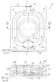
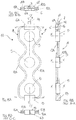
- a first embodiment of a heat exchanger 10 is disclosed in accordance with the present invention, extending between the combustion chamber 6A of said burner 6, arranged in particular in a lower region of the cooking chamber 2, and an exhaust manifold 14 connectable to said exhaust opening 7 formed on the ceiling 2C of said cooking chamber 2, as shown in figures 1A and 1C .
- the two tube bundles 11 extend around the fan 5 in a manner symmetrical to a diametrical axis of the same, and in particular, advantageously, a vertical axis Y-Y passing through the center of the fan 5.
- Each of the two tube bundles 11 forming said heat exchanger 10 comprises a plurality of tubular portions 12A, 12B, 12C lying on parallel planes and connected in series, each of which being formed by a single tube.
- a first tubular portion 12A is provided, directly connected with a first end to said combustion chamber 6A, and extending from the latter to near the ceiling 2C of said cooking chamber 2, a second tubular portion 12B, joined with a first end to the second end of said first portion 12A and extending around said fan 5 so as to have a second end near the bottom 2B of the cooking chamber 2, and a third tubular portion 12C joined with a first end to the second portion 12B and connectable, with the opposite end, to said exhaust opening 7 through the interposition of an exhaust manifold 14 that is substantially vertical.
- Said three portions 12A, 12B, 12C lie essentially along corresponding reciprocally parallel planes and are arranged substantially orthogonal to the axis of rotation X-X of the fan 5, and are connected in series to each other, with an axial extension with respect to said axis of rotation X-X, through a first and a second return element 13, 15, each defining an exchange cavity common to both tube bundles 11 of the heat exchanger 10.
- a terminal confluence element 16 is arranged at the second ends of the third tubular portions 12C of both tube bundles 11 to merge the fumes flowing through them and feed them into the exhaust manifold 14.
- said second return element 15 is disposed substantially coaxial with said combustion chamber 6A and can if necessary be joined to it through the interposition of a first partition baffle 61; similarly, said confluence element 16 is preferably disposed coaxial with said first return element 13 and can be joined to the latter by the interposition of a second partition baffle 62.
- said tubular portions 12A, 12B and 12C are adapted to carry the gases in opposite flow directions; in particular, as shown by the arrows in figure 2 , initially the gases course through said first portion 12A in an essentially ascending direction of flow, to then be returned by said first return element 13 and fed into the second portion 12B, in which the gases flow in an essentially descending direction, and finally they are returned again by said second return element 15 and fed into the third portion 12C, in an ascending direction of flow, until they reach said confluence element 16, which is common to both tube bundles 11 and placed preferably above said fan 5, and finally the gases reach the exhaust opening 7 through said exhaust manifold 14.
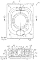
- a heat exchanger 10 is illustrated in accordance with a second embodiment of the present invention; it is substantially similar to the one previously described, being provided with a pair of tube bundles 11 extending advantageously in symmetrical manner with respect to the vertical axis Y-Y of the fan 5 between the combustion chamber 6A of the burner 6, arranged near the bottom wall 2B of the cooking chamber 2, and an exhaust opening 7, formed in the ceiling 2C of the same, as shown in figures 1A and 1C .
- said tube bundles 11 each comprise a plurality of tubular portions arranged on reciprocally parallel planes and orthogonal to the axis of rotation X-X of the fan 5 and connected appropriately through a first and a second return element 13, 15 to extend in an axial direction with respect to said axis of rotation X-X.
- each tube bundle 11 of said heat exchanger 10 comprises a first tubular portion 12A' formed by a pair of tubes joined with a first end to said combustion chamber 6A, and being both connected with a respective second end to said first return element 13 arranged above said fan 5 near the ceiling 2C of the cooking chamber 2, defining advantageously a cavity that is common to both tube bundles 11 of the heat exchanger 10.
- a second tubular portion 12B is foreseen, joined to said first return element 13, as well as a third tubular portion 12C, said second and third tubular portion 12B, 12C being arranged between them in succession and joined by the interposition of a second return element 15 provided in proximity of the bottom 2B of the cooking chamber 2 and defining a cavity common to both tube bundles 11.
- said second return element 15 is disposed substantially coaxial with said combustion chamber 6A and can if necessary be joined to it by the interposition of a first partition baffle 61.
- the end parts of the third tubular portions 12C of both tube bundles 11 are advantageously joined to a confluence element 16 preferably coaxial with said first return element 13 and separated from the latter by a second partition baffle 62.
- said pair of tubes forming said first portion 12A' are both directly communicating with the combustion chamber 6A of the burner 6, being essentially arranged parallel to each other and therefore both having the gases course through them in an ascending flow.
- the exhaust gases are then returned by said first return element 13 and fed into the tube forming said second portion 12B, which is thus arranged in series with respect to said first portion 12A', being coursed in a descending direction, to then be returned again from said second return element 15 and fed into the tube forming said third portion 12C, with an ascending direction of flow, until they arrive at said confluence element 16, which is common to both tube bundles 11 and placed preferably above said fan 5, and finally they reach the exhaust opening 7 through said exhaust manifold 14.
- FIGS 5A - 5E is illustrated a variant embodiment of the heat exchanger just described, which is different from the latter for the fact of being adapted to be joined to an oven structure 1 in which the exhaust opening 7 is formed on the side wall 2A on which said fan 5 is mounted, and preferably located in proximity of the ceiling 2C of the cooking chamber 2, and said exhaust manifold 14, connected to the confluence element 16 common to both tube bundles 11, is arranged substantially parallel to the axis of rotation X-X of the fan 5.
- This variant embodiment is advantageous in the case in which two or more superimposed oven structures 1 are to be used.
- each tube bundle 11 is provided with its own first return element 13, distinct and separate from the corresponding first return element 13 arranged symmetrically on the other tube bundle 11.
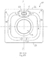
- FIGS 6A - 6C is illustrated a heat exchanger 10 according to a third embodiment of the present invention.
- this heat exchanger 10 is adapted to be joined to an oven structure 1 in which said burner 6 is positioned near the ceiling 2C of the cooking chamber 2 and adjacent to the exhaust opening 7.
- each tube bundle 11 of said heat exchanger 10 comprises at least two tubular portions 12A, 12B, each formed by a single tube, lying on two planes parallel to each other and substantially perpendicular to the axis of rotation X-X of the fan 5, connected in series with an axial extension with respect to said axis of rotation X-X through the interposition of a return element 13, advantageously common for both tube bundles 11, and coursed by the exhaust gases in opposite directions, as shown by the arrows.
- said confluence element 16 is arranged substantially coaxial with said combustion chamber 6A and if necessary can be joined to it by the interposition of a first partition baffle 61.
- FIGS 7A - 7E is illustrated a variant embodiment of the just described heat exchanger 10, substantially similar to the one made according to the embodiment just illustrated, foreseeing a pair of tube bundles 11 extending symmetrically around said fan 5 between the combustion chamber 6A of the burner 6, arranged in the upper part of said cooking chamber 2, and the exhaust opening 7, formed near said burner 6.
- said tube bundles 11 each comprise two tubular portions 12A', 12B' lying on planes parallel and orthogonal to the axis of rotation X-X of the fan 5, connected in series through a return element 13 and adapted to be traversed by the exhaust gases in opposite directions of flow.
- said first portion 12A' is formed by a pair of tubes, both joined with one first end to said combustion chamber 6A and both connected with a respective second end to said return element 13, preferably defining within it a cavity common to both tube bundles 11, and to which is also joined said second portion 12B', also formed by a pair of tubes.
- said pair of tubes forming said first portion 12A' are both directly communicating with the combustion chamber 6A of the burner 6, being essentially arranged in parallel and being therefore both traversed in a descending direction of flow; the gases are then returned by said return element 13 and fed into the tubes placed in parallel to each other and forming said second portion 12B', which is thus disposed in series with respect to said first portion 12A', both flowed through by the gases in an ascending direction, to merge in a confluence element 16 common to both tube bundles 11, and finally reach the exhaust opening 7 through said exhaust header 14.
- said confluence element 16 is arranged substantially coaxial with said combustion chamber 6A and can if necessary be associated to it through the interposition of a first partition baffle 61.
- a third partition baffle 63 can if needed be provided inside said first return element 13 to maintain separate the flows of exhaust gases circulating in the two tube bundles 11 and avoid the generation of noise.
- FIG. 8A - 8C is shown an oven structure 1 inside of which is built-in a heat exchanger 10 according to a fourth embodiment of the present invention.
- said heat exchanger 10 extends between the combustion chamber 6A of said burner 6, arranged in particular in a lower area of the cooking chamber 2, laterally with respect to the vertical axis of the fan 5, and an exhaust opening 7 formed on the ceiling 2C of said cooking chamber 2, in a lateral and preferably opposite area of the fan 5 with respect to the positioning of the combustion chamber 6A of the burner 6.
- the two tube bundles 11 extend around the fan 5 advantageously in a symmetrical manner with respect to an axis diametrical to the same; however, in this case, said tube bundles 11 are symmetrical with respect to an axis M-M inclined with respect to the vertical axis Y-Y passing through the center of the fan 5.
- each tube bundle 11 of said heat exchanger 10 comprises a first tubular portion 12A' formed by a pair of tubes joined with a first end to said combustion chamber 6A, and both connected with a respective second end to said first return element 13 arranged near the ceiling 2C of the cooking chamber 2, in a region diametrically opposite the fan 5 with respect to the position of said burner 6, and advantageously defining a cavity common for both tube bundles 11 of the heat exchanger 10.
- the embodiment also foresees a second tubular portion 12B, joined to said first return element 13, and a third tubular portion 12C, said second and third tubular portion 12B, 12C each being formed by a single tube and arranged in succession to each other, joined with an axial extension with respect to said axis of rotation X-X by the interposition of a second return element 15 included in proximity of the bottom 2B of the cooking chamber 2 and defining a cavity common to both tube bundles 11.
- said second return element 15 is arranged substantially coaxial with said combustion chamber 6A and if necessary can be joined to it by the interposition of a first partition baffle 61.
- terminal ends of the third tubular portions 12C of both tube bundles 11 are advantageously joined to a confluence element 16, preferably coaxial to said first return element 13 and separated from the latter by a second partition baffle 62.
- said pair of tubes forming said first portion 12A' are both directly communicating with the combustion chamber 6A of the burner 6, being arranged essentially parallel to each other and therefore both having the gases flowing through them in an ascending direction.
- the exhaust gases are then returned from said first return element 13 and fed into the tube forming said second portion 12B, which is thus disposed in series with respect to said first portion 12A', being coursed by the gases in a descending direction of flow, to then be returned again from said second return element 15 and introduced into the tube forming said third portion 12C, with an ascending direction of flow, until they arrive at said confluence element 16, common to both tube bundles 11 and placed preferably above said fan 5, and finally they reach the exhaust opening 7 through said exhaust manifold 14.
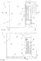
- a heat exchanger 10 is illustrated in accordance with a fifth embodiment of the invention; said heat exchanger 10 is functionally substantially identical to the heat exchanger illustrated in figures 6A - 6C but it has the distinguishing feature of being installed in a cooking oven structure equipped with a plurality of fans 5, three for example, stacked and preferably aligned with their centers of rotation along a vertical axis Y-Y.
- the tube bundles 11 of said heat exchanger 10 can, if necessary, be shaped in an undulating manner, so as follow the contours of said fans 5.
- the heat exchanger 10 is also adapted to be connected to an oven structure in which said burner 6 is positioned near the ceiling of the cooking chamber and adjacent to the exhaust opening 7.
- each tube bundle 11 of said heat exchanger 10 comprises at least two tubular portions 12A, 12B, each formed by a single tube, lying on planes parallel to each other and substantially perpendicular to the axis of rotation X-X of the fan 5, connected in series with an axial extension with respect to said axis of rotation X-X by the interposition of a return element 13, and carrying the exhaust gases in opposite directions, as is shown by the arrows in figure 11B .
- said confluence element 16 is arranged substantially coaxial with said combustion chamber 6A and can if necessary be joined to it by the interposition of a first partition baffle 61.
- a third partition baffle 63 may if necessary be provided inside said return element 13 to maintain separate the flows of exhaust gases circulating in the two tube bundles 11 and avoid the generation of noise.
- a heat exchanger 10 can be configured in such a way as to adapt itself to the arrangement of the burner 6 and of the exhaust opening 7 of the cooking chamber 2 of the gas oven 1 to which it is to be applied and to the number and arrangement of the fans 5.
- a heat exchanger 10 will be provided with two tube bundles 11 extending around the fan 5 but asymmetrical with respect to an imaginary axis connecting the exhaust opening 7 and the burner 6.
- each of the two tube bundles 11 of a heat exchanger 10 according to the present invention has at least two tubular portions adapted to be traversed by the exhaust gases in opposite directions of flow, an improvement in the distribution of the temperature of the air can be observed inside the cooking chamber 2, without however imposing an increase of the spaces required to house it.
- the distribution of the temperatures is most uniform along a vertical axis of reference, thus giving an optimal homogeneous cooking of the food.
- a heat exchanger 10 is so compact as to make it sometime possible to use, with small and low-cost alterations, previous cooking chambers of electric ovens to obtain other cooking chambers that are adapted to be used with gas heating, thus allowing a reduction of the industrial costs connected with the production of the ovens.
- a heat exchanger 10 according to the fourth embodiment of the invention can be advantageously applied to ovens in which, for purposes of containing the dimensions, the burner 6 is positioned laterally with respect to the vertical axis passing through the center of the fan 5, while still guaranteeing an excellent efficiency in terms of heat exchange, and an acceptable uniformity in the distribution of the temperatures in the cooking chamber 2.
- an exchanger as defined by the enclosed claim 1 can be configured in the most suitable manner to extend around the fan 5, or fans 5, between the burner 6 and the exhaust opening 7, without thereby departing from the scope of protection of the present invention.
Landscapes
- Engineering & Computer Science (AREA)
- Mechanical Engineering (AREA)
- General Engineering & Computer Science (AREA)
- Physics & Mathematics (AREA)
- Thermal Sciences (AREA)
- Chemical & Material Sciences (AREA)
- Combustion & Propulsion (AREA)
- Heat-Exchange Devices With Radiators And Conduit Assemblies (AREA)
Claims (14)
- Wärmetauscher (10) eines Gasverbrennungsofens (1) mit mindestens zwei Rohrbündeln (11), die ausgebildet sind, sich auf gegenüberliegenden Seiten zwischen einem Abgaseinlass (6A), der mit einem Gasbrenner (6) des Ofens (1) verbindbar ist, und zwischen einem Abgasauslass (7) zu erstrecken, der mit einer Abgasverteilungsleitung (14) des Ofens (1) verbindbar ist, wobei jedes Rohrbündel (11) mindestens zwei Rohrbereiche (12A, 12B, 12C, 12A', 12B') aufweist, wovon jeder durch mindestens ein Rohr gebildet ist, wobei die Rohrbereiche in Ebenen liegen, die parallel zueinander und senkrecht zu einer horizontalen Achse (X-X) sind und durch mindestens ein Rückleitungselement (13, 15) in Reihe derart miteinander verbunden sind, dass jeder Rohrbereich ausgebildet ist, von den Abgasen in einer Strömungsrichtung, die entgegengesetzt zu einer Strömungsrichtung eines Rohrbereichs ist, der auf einer benachbarten Ebene liegt, durchlaufen zu werden,
dadurch gekennzeichnet, dass
die Rohrbereiche (12A, 12B, 12C, 12A', 12B') benachbart zueinander, überlappend und axial ausgerichtet in Bezug auf die horizontale Achse (X-X) angeordnet sind. - Wärmetauscher (10) nach Anspruch 1, wobei mindestens einer der Rohrbereiche (12A, 12B, 12C) durch ein einziges Rohr gebildet ist.
- Wärmetauscher (10) nach Anspruch 1 oder 2, wobei mindestens einer der Rohrbereiche (12A', 12B') durch mehrere Rohre gebildet ist, die parallel angeordnet sind und in Ebenen liegen, die parallel zueinander und senkrecht zu der horizontalen Achse (X-X) sind.
- Wärmetauscher (10) nach einem der vorhergehenden Ansprüche, wobei die Rohrbereiche (12A, 12B, 12C, 12A', 12B') im Querschnitt eine Kreisform oder eine ovale Form haben.
- Wärmetauscher (10) nach einem der vorhergehenden Ansprüche, wobei die Abmessungen der Querschnitte der Rohre, die die Rohrbereiche (12A, 12B, 12C, 12A', 12B') bilden, über die gesamte Länge des jeweiligen Rohrbündels (11) gleichbleibend sind.
- Wärmetauscher (10) nach einem der Ansprüche 1 bis 4, wobei die Abmessungen der Querschnitte der Rohre, die die Rohrbereiche (12A, 12B, 12C, 12A', 12B') bilden, entlang der Länge des jeweiligen Rohrbündels (11) progressiv kleiner werden.
- Wärmetauscher (10) nach einem der vorhergehenden Ansprüche, wobei das mindestens eine Rückleitungselement (13, 15) für beide Rohrbündel (11) gemeinsam ist.
- Wärmetauscher (10) nach Anspruch 7, wobei das mindestens eine Rückleitungselement (13, 15) entlang einer Achse verläuft, die im Wesentlichen parallel zu der horizontalen Achse (X-Nix) ist.
- Wärmetauscher (10) nach einem der vorhergehenden Ansprüche, wobei die mindestens zwei Rohrbündel (11) sich symmetrisch zwischen dem Abgaseinlass (6A) und dem Abgasauslass (7) erstrecken.
- Gasverbrennungsofen (1) mit einer Kochkammer (2), die mit einer Bodenwand (28) und einer Deckenwand (2C) versehen ist, einem Gebläse (5) mit einer horizontalen Drehachse (X-X), einem vorgemischten Brenner (6), einer Abgasverteilungsleitungen (14) und einem Wärmetauscher (10) nach einem der vorhergehenden Ansprüche.
- Gasverbrennungsofen (1) nach Anspruch 10, wobei der Brenner (6) in der Nähe der Deckenwand (2C) angeordnet ist, der Wärmetauscher (10) einen ersten Rohrbereich (12A, 12A'), der ausgebildet ist, von den Abgasen in einer absteigenden Strömungsrichtung durchlaufen zu werden, und einen zweiten Rohrbereich (12B, 12B') aufweist, der ausgebildet ist, von den Abgasen in einer aufsteigenden Strömungsrichtung durchlaufen zu werden, wobei der erste und der zweite Rohrbereich durch ein Rückleitungselement (13) in Reihe miteinander verbunden sind.
- Gasverbrennungsofen (1) nach Anspruch 10, wobei der Brenner (6) in der Nähe der Bodenwand (2B) angeordnet ist, und der Wärmetauscher (10) einen ersten Rohrbereich (12A, 12A'), der ausgebildet ist, von den Abgasen in einer aufsteigenden Strömungsrichtung durchlaufen zu werden, und einen zweiten Rohrbereich (12B, 12B') aufweist, der ausgebildet ist, von den Abgasen in einer absteigenden Strömungsrichtung durchlaufen zu werden, und wobei der erste und der zweite Rohrbereich durch ein erstes Rückleitungselement (13) miteinander in Reihe verbunden sind, und ein dritter Rohrbereich (12C) vorgesehen ist, der ausgebildet ist, von den Abgasen in einer aufsteigenden Strömungsrichtung durchlaufen zu werden und der mit dem zweiten Rohrbereich (12B, 12B') durch ein zweites Rückleitungselement (15) in Reihe verbunden ist.
- Gasverbrennungsofen (1) nach einem der Ansprüche 10 bis 12, wobei der Brenner (6) in Bezug auf das Gebläse (5) seitlich angeordnet ist, und wobei der Wärmetauscher (10) ein Paar aus Rohrbündeln (11) aufweist, die symmetrisch um das Gebläse (5) angeordnet sind.
- Gasverbrennungsofen (1) nach einem der Ansprüche 10 bis 12, wobei der Brenner (6) in Bezug auf das Gebläse (5) seitlich angeordnet ist und wobei der Wärmetauscher (10) ein Paar aus Rohrbündeln (12) aufweist, die asymmetrisch um das Gebläse (5) angeordnet sind.
Priority Applications (1)
| Application Number | Priority Date | Filing Date | Title |
|---|---|---|---|
| PL17191672T PL3299730T3 (pl) | 2016-09-21 | 2017-09-18 | Wymiennik ciepła do gazowego pieca kuchennego |
Applications Claiming Priority (2)
| Application Number | Priority Date | Filing Date | Title |
|---|---|---|---|
| IT102016000094910A IT201600094910A1 (it) | 2016-09-21 | 2016-09-21 | Scambiatore di calore per forni di cottura |
| IT102016000115084A IT201600115084A1 (it) | 2016-09-21 | 2016-11-15 | Scambiatore di calore per forni di cottura |
Publications (2)
| Publication Number | Publication Date |
|---|---|
| EP3299730A1 EP3299730A1 (de) | 2018-03-28 |
| EP3299730B1 true EP3299730B1 (de) | 2019-07-31 |
Family
ID=59858656
Family Applications (1)
| Application Number | Title | Priority Date | Filing Date |
|---|---|---|---|
| EP17191672.9A Active EP3299730B1 (de) | 2016-09-21 | 2017-09-18 | Wärmetauscher für gasbackofen |
Country Status (2)
| Country | Link |
|---|---|
| EP (1) | EP3299730B1 (de) |
| PL (1) | PL3299730T3 (de) |
Cited By (1)
| Publication number | Priority date | Publication date | Assignee | Title |
|---|---|---|---|---|
| EP4381947A1 (de) * | 2022-12-07 | 2024-06-12 | The Middleby Corporation | Durchlaufofen |
Families Citing this family (2)
| Publication number | Priority date | Publication date | Assignee | Title |
|---|---|---|---|---|
| PL237178B1 (pl) | 2018-12-18 | 2021-03-22 | Retech Spolka Z Ograniczona Odpowiedzialnoscia | Pochłaniacz pary ze skraplaczem do pieca gastronomicznego, zwłaszcza pieca konwekcyjno-parowego |
| CN111981678B (zh) * | 2019-05-24 | 2021-07-23 | 青岛佰腾科技有限公司 | 一种水位调节的热水器 |
Family Cites Families (10)
| Publication number | Priority date | Publication date | Assignee | Title |
|---|---|---|---|---|
| US4648377A (en) * | 1986-05-01 | 1987-03-10 | Hobart Corporation | Gas convection oven and heat exchanger therefor |
| DE4125696C1 (en) * | 1991-08-02 | 1993-02-18 | Eloma Gmbh Grosskuechentechnik, 8031 Maisach, De | Steam cooker with air fan wheel - vaporises water before reaching heaters with water inlets controlled by valves |
| ES2114782B1 (es) * | 1994-12-21 | 1999-03-01 | Fagor S Coop | Horno de cocinado comercial a gas combinado. |
| JP3053591B2 (ja) * | 1997-06-02 | 2000-06-19 | 株式会社コメットカトウ | 加熱調理機 |
| DE10220625A1 (de) * | 2002-05-08 | 2003-11-20 | Lainox Ali Spa Vittorio Veneto | Gas-Backofen mit Konvektion mit hoher Leistung, insbesondere für die Zubereitung von Speisen |
| DE102005047415A1 (de) * | 2004-10-01 | 2006-04-13 | Wss Gmbh | Vorrichtung zum Verteilen von Abgasen aus einer Brennkammer |
| DE102008058718A1 (de) * | 2008-11-24 | 2010-05-27 | Rational Ag | Gargerät mit Wärmetauscher |
| JP5186511B2 (ja) * | 2010-01-08 | 2013-04-17 | 株式会社コメットカトウ | スチームコンベクションオーブン |
| KR101381562B1 (ko) * | 2012-10-31 | 2014-04-04 | 린나이코리아 주식회사 | 타원 단면식 열교환기 및 이를 구비한 컨벡션 오븐 |
| WO2014196676A1 (ko) * | 2013-06-07 | 2014-12-11 | 이노엔 주식회사 | 조리기기용 열교환기 |
-
2017
- 2017-09-18 EP EP17191672.9A patent/EP3299730B1/de active Active
- 2017-09-18 PL PL17191672T patent/PL3299730T3/pl unknown
Non-Patent Citations (1)
| Title |
|---|
| None * |
Cited By (1)
| Publication number | Priority date | Publication date | Assignee | Title |
|---|---|---|---|---|
| EP4381947A1 (de) * | 2022-12-07 | 2024-06-12 | The Middleby Corporation | Durchlaufofen |
Also Published As
| Publication number | Publication date |
|---|---|
| PL3299730T3 (pl) | 2019-11-29 |
| EP3299730A1 (de) | 2018-03-28 |
Similar Documents
| Publication | Publication Date | Title |
|---|---|---|
| US4648377A (en) | Gas convection oven and heat exchanger therefor | |
| EP0344743B1 (de) | Umluft- Gaskochherd | |
| EP3299730A1 (de) | Wärmetauscher für backofen | |
| EP1962043B1 (de) | Mehrkanaliger Wärmetauscher | |
| US20160320072A1 (en) | Direct-heating fan oven | |
| JP6198089B2 (ja) | 調理機器用熱交換器 | |
| CN103620311B (zh) | 高效炉灶 | |
| KR101278621B1 (ko) | 조리기기용 열교환기 | |
| CN110537834B (zh) | 一种蒸烤箱 | |
| CN217274302U (zh) | 一种燃气灶及具有烹饪装置的集成灶 | |
| JP6011669B1 (ja) | 室外機 | |
| CN109645848A (zh) | 烹饪电器 | |
| KR102511728B1 (ko) | 열교환기 및 열교환기 제작방법 | |
| ES2749799T3 (es) | Intercambiador de calor para horno de cocción de gas | |
| CN105444255A (zh) | 发热装置及具有其的电取暖装置 | |
| CN222075024U (zh) | 一种烹饪器以及集成灶 | |
| TR201802103T4 (tr) | Pişirme cihazı. | |
| CN223554695U (zh) | 烹饪设备 | |
| CN221153773U (zh) | 一种烹饪装置及具有该烹饪装置的集成灶 | |
| US20130174832A1 (en) | Appliance baffle system | |
| EP4563887A1 (de) | Kochgerät | |
| CN219206604U (zh) | 一种排气冷凝结构及蒸制烹饪装置 | |
| CN220024790U (zh) | 一种具有烤功能的烹饪内胆结构及烹饪设备 | |
| US5540211A (en) | Pocket heat exchanger | |
| KR20250083820A (ko) | 조리기기 |
Legal Events
| Date | Code | Title | Description |
|---|---|---|---|
| PUAI | Public reference made under article 153(3) epc to a published international application that has entered the european phase |
Free format text: ORIGINAL CODE: 0009012 |
|
| STAA | Information on the status of an ep patent application or granted ep patent |
Free format text: STATUS: THE APPLICATION HAS BEEN PUBLISHED |
|
| AK | Designated contracting states |
Kind code of ref document: A1 Designated state(s): AL AT BE BG CH CY CZ DE DK EE ES FI FR GB GR HR HU IE IS IT LI LT LU LV MC MK MT NL NO PL PT RO RS SE SI SK SM TR |
|
| AX | Request for extension of the european patent |
Extension state: BA ME |
|
| STAA | Information on the status of an ep patent application or granted ep patent |
Free format text: STATUS: REQUEST FOR EXAMINATION WAS MADE |
|
| 17P | Request for examination filed |
Effective date: 20180621 |
|
| RAV | Requested validation state of the european patent: fee paid |
Extension state: MA Effective date: 20180625 |
|
| RBV | Designated contracting states (corrected) |
Designated state(s): AL AT BE BG CH CY CZ DE DK EE ES FI FR GB GR HR HU IE IS IT LI LT LU LV MC MK MT NL NO PL PT RO RS SE SI SK SM TR |
|
| STAA | Information on the status of an ep patent application or granted ep patent |
Free format text: STATUS: EXAMINATION IS IN PROGRESS |
|
| 17Q | First examination report despatched |
Effective date: 20180830 |
|
| GRAP | Despatch of communication of intention to grant a patent |
Free format text: ORIGINAL CODE: EPIDOSNIGR1 |
|
| STAA | Information on the status of an ep patent application or granted ep patent |
Free format text: STATUS: GRANT OF PATENT IS INTENDED |
|
| RIC1 | Information provided on ipc code assigned before grant |
Ipc: F28D 1/047 20060101ALI20190430BHEP Ipc: F24C 15/32 20060101AFI20190430BHEP Ipc: F28D 7/00 20060101ALI20190430BHEP Ipc: F28D 1/053 20060101ALI20190430BHEP Ipc: F28F 13/08 20060101ALI20190430BHEP Ipc: F28D 1/04 20060101ALI20190430BHEP |
|
| INTG | Intention to grant announced |
Effective date: 20190522 |
|
| GRAS | Grant fee paid |
Free format text: ORIGINAL CODE: EPIDOSNIGR3 |
|
| GRAA | (expected) grant |
Free format text: ORIGINAL CODE: 0009210 |
|
| STAA | Information on the status of an ep patent application or granted ep patent |
Free format text: STATUS: THE PATENT HAS BEEN GRANTED |
|
| AK | Designated contracting states |
Kind code of ref document: B1 Designated state(s): AL AT BE BG CH CY CZ DE DK EE ES FI FR GB GR HR HU IE IS IT LI LT LU LV MC MK MT NL NO PL PT RO RS SE SI SK SM TR |
|
| REG | Reference to a national code |
Ref country code: CH Ref legal event code: EP Ref country code: GB Ref legal event code: FG4D |
|
| REG | Reference to a national code |
Ref country code: CH Ref legal event code: NV Representative=s name: PATENTANWAELTE SCHAAD, BALASS, MENZL AND PARTN, CH Ref country code: AT Ref legal event code: REF Ref document number: 1161294 Country of ref document: AT Kind code of ref document: T Effective date: 20190815 |
|
| REG | Reference to a national code |
Ref country code: IE Ref legal event code: FG4D |
|
| REG | Reference to a national code |
Ref country code: DE Ref legal event code: R096 Ref document number: 602017005681 Country of ref document: DE |
|
| REG | Reference to a national code |
Ref country code: NL Ref legal event code: FP |
|
| REG | Reference to a national code |
Ref country code: LT Ref legal event code: MG4D |
|
| REG | Reference to a national code |
Ref country code: AT Ref legal event code: MK05 Ref document number: 1161294 Country of ref document: AT Kind code of ref document: T Effective date: 20190731 |
|
| PG25 | Lapsed in a contracting state [announced via postgrant information from national office to epo] |
Ref country code: PT Free format text: LAPSE BECAUSE OF FAILURE TO SUBMIT A TRANSLATION OF THE DESCRIPTION OR TO PAY THE FEE WITHIN THE PRESCRIBED TIME-LIMIT Effective date: 20191202 Ref country code: LT Free format text: LAPSE BECAUSE OF FAILURE TO SUBMIT A TRANSLATION OF THE DESCRIPTION OR TO PAY THE FEE WITHIN THE PRESCRIBED TIME-LIMIT Effective date: 20190731 Ref country code: BG Free format text: LAPSE BECAUSE OF FAILURE TO SUBMIT A TRANSLATION OF THE DESCRIPTION OR TO PAY THE FEE WITHIN THE PRESCRIBED TIME-LIMIT Effective date: 20191031 Ref country code: SE Free format text: LAPSE BECAUSE OF FAILURE TO SUBMIT A TRANSLATION OF THE DESCRIPTION OR TO PAY THE FEE WITHIN THE PRESCRIBED TIME-LIMIT Effective date: 20190731 Ref country code: HR Free format text: LAPSE BECAUSE OF FAILURE TO SUBMIT A TRANSLATION OF THE DESCRIPTION OR TO PAY THE FEE WITHIN THE PRESCRIBED TIME-LIMIT Effective date: 20190731 Ref country code: AT Free format text: LAPSE BECAUSE OF FAILURE TO SUBMIT A TRANSLATION OF THE DESCRIPTION OR TO PAY THE FEE WITHIN THE PRESCRIBED TIME-LIMIT Effective date: 20190731 Ref country code: NO Free format text: LAPSE BECAUSE OF FAILURE TO SUBMIT A TRANSLATION OF THE DESCRIPTION OR TO PAY THE FEE WITHIN THE PRESCRIBED TIME-LIMIT Effective date: 20191031 Ref country code: FI Free format text: LAPSE BECAUSE OF FAILURE TO SUBMIT A TRANSLATION OF THE DESCRIPTION OR TO PAY THE FEE WITHIN THE PRESCRIBED TIME-LIMIT Effective date: 20190731 |
|
| PG25 | Lapsed in a contracting state [announced via postgrant information from national office to epo] |
Ref country code: IS Free format text: LAPSE BECAUSE OF FAILURE TO SUBMIT A TRANSLATION OF THE DESCRIPTION OR TO PAY THE FEE WITHIN THE PRESCRIBED TIME-LIMIT Effective date: 20191130 Ref country code: LV Free format text: LAPSE BECAUSE OF FAILURE TO SUBMIT A TRANSLATION OF THE DESCRIPTION OR TO PAY THE FEE WITHIN THE PRESCRIBED TIME-LIMIT Effective date: 20190731 Ref country code: RS Free format text: LAPSE BECAUSE OF FAILURE TO SUBMIT A TRANSLATION OF THE DESCRIPTION OR TO PAY THE FEE WITHIN THE PRESCRIBED TIME-LIMIT Effective date: 20190731 Ref country code: AL Free format text: LAPSE BECAUSE OF FAILURE TO SUBMIT A TRANSLATION OF THE DESCRIPTION OR TO PAY THE FEE WITHIN THE PRESCRIBED TIME-LIMIT Effective date: 20190731 Ref country code: GR Free format text: LAPSE BECAUSE OF FAILURE TO SUBMIT A TRANSLATION OF THE DESCRIPTION OR TO PAY THE FEE WITHIN THE PRESCRIBED TIME-LIMIT Effective date: 20191101 |
|
| REG | Reference to a national code |
Ref country code: ES Ref legal event code: FG2A Ref document number: 2749799 Country of ref document: ES Kind code of ref document: T3 Effective date: 20200323 |
|
| PG25 | Lapsed in a contracting state [announced via postgrant information from national office to epo] |
Ref country code: RO Free format text: LAPSE BECAUSE OF FAILURE TO SUBMIT A TRANSLATION OF THE DESCRIPTION OR TO PAY THE FEE WITHIN THE PRESCRIBED TIME-LIMIT Effective date: 20190731 Ref country code: DK Free format text: LAPSE BECAUSE OF FAILURE TO SUBMIT A TRANSLATION OF THE DESCRIPTION OR TO PAY THE FEE WITHIN THE PRESCRIBED TIME-LIMIT Effective date: 20190731 Ref country code: EE Free format text: LAPSE BECAUSE OF FAILURE TO SUBMIT A TRANSLATION OF THE DESCRIPTION OR TO PAY THE FEE WITHIN THE PRESCRIBED TIME-LIMIT Effective date: 20190731 |
|
| PG25 | Lapsed in a contracting state [announced via postgrant information from national office to epo] |
Ref country code: SK Free format text: LAPSE BECAUSE OF FAILURE TO SUBMIT A TRANSLATION OF THE DESCRIPTION OR TO PAY THE FEE WITHIN THE PRESCRIBED TIME-LIMIT Effective date: 20190731 Ref country code: CZ Free format text: LAPSE BECAUSE OF FAILURE TO SUBMIT A TRANSLATION OF THE DESCRIPTION OR TO PAY THE FEE WITHIN THE PRESCRIBED TIME-LIMIT Effective date: 20190731 Ref country code: MC Free format text: LAPSE BECAUSE OF FAILURE TO SUBMIT A TRANSLATION OF THE DESCRIPTION OR TO PAY THE FEE WITHIN THE PRESCRIBED TIME-LIMIT Effective date: 20190731 Ref country code: IS Free format text: LAPSE BECAUSE OF FAILURE TO SUBMIT A TRANSLATION OF THE DESCRIPTION OR TO PAY THE FEE WITHIN THE PRESCRIBED TIME-LIMIT Effective date: 20200224 Ref country code: SM Free format text: LAPSE BECAUSE OF FAILURE TO SUBMIT A TRANSLATION OF THE DESCRIPTION OR TO PAY THE FEE WITHIN THE PRESCRIBED TIME-LIMIT Effective date: 20190731 |
|
| REG | Reference to a national code |
Ref country code: DE Ref legal event code: R097 Ref document number: 602017005681 Country of ref document: DE |
|
| PLBE | No opposition filed within time limit |
Free format text: ORIGINAL CODE: 0009261 |
|
| STAA | Information on the status of an ep patent application or granted ep patent |
Free format text: STATUS: NO OPPOSITION FILED WITHIN TIME LIMIT |
|
| PG2D | Information on lapse in contracting state deleted |
Ref country code: IS |
|
| PG25 | Lapsed in a contracting state [announced via postgrant information from national office to epo] |
Ref country code: LU Free format text: LAPSE BECAUSE OF NON-PAYMENT OF DUE FEES Effective date: 20190918 Ref country code: IE Free format text: LAPSE BECAUSE OF NON-PAYMENT OF DUE FEES Effective date: 20190918 Ref country code: IS Free format text: LAPSE BECAUSE OF FAILURE TO SUBMIT A TRANSLATION OF THE DESCRIPTION OR TO PAY THE FEE WITHIN THE PRESCRIBED TIME-LIMIT Effective date: 20191030 |
|
| 26N | No opposition filed |
Effective date: 20200603 |
|
| PG25 | Lapsed in a contracting state [announced via postgrant information from national office to epo] |
Ref country code: SI Free format text: LAPSE BECAUSE OF FAILURE TO SUBMIT A TRANSLATION OF THE DESCRIPTION OR TO PAY THE FEE WITHIN THE PRESCRIBED TIME-LIMIT Effective date: 20190731 |
|
| PG25 | Lapsed in a contracting state [announced via postgrant information from national office to epo] |
Ref country code: CY Free format text: LAPSE BECAUSE OF FAILURE TO SUBMIT A TRANSLATION OF THE DESCRIPTION OR TO PAY THE FEE WITHIN THE PRESCRIBED TIME-LIMIT Effective date: 20190731 |
|
| VS25 | Lapsed in a validation state [announced via postgrant information from nat. office to epo] |
Ref country code: MA Free format text: LAPSE BECAUSE OF FAILURE TO SUBMIT A TRANSLATION OF THE DESCRIPTION OR TO PAY THE FEE WITHIN THE PRESCRIBED TIME-LIMIT Effective date: 20190731 |
|
| PG25 | Lapsed in a contracting state [announced via postgrant information from national office to epo] |
Ref country code: MT Free format text: LAPSE BECAUSE OF FAILURE TO SUBMIT A TRANSLATION OF THE DESCRIPTION OR TO PAY THE FEE WITHIN THE PRESCRIBED TIME-LIMIT Effective date: 20190731 Ref country code: HU Free format text: LAPSE BECAUSE OF FAILURE TO SUBMIT A TRANSLATION OF THE DESCRIPTION OR TO PAY THE FEE WITHIN THE PRESCRIBED TIME-LIMIT; INVALID AB INITIO Effective date: 20170918 |
|
| PG25 | Lapsed in a contracting state [announced via postgrant information from national office to epo] |
Ref country code: MK Free format text: LAPSE BECAUSE OF FAILURE TO SUBMIT A TRANSLATION OF THE DESCRIPTION OR TO PAY THE FEE WITHIN THE PRESCRIBED TIME-LIMIT Effective date: 20190731 |
|
| P01 | Opt-out of the competence of the unified patent court (upc) registered |
Effective date: 20230328 |
|
| REG | Reference to a national code |
Ref country code: CH Ref legal event code: U11 Free format text: ST27 STATUS EVENT CODE: U-0-0-U10-U11 (AS PROVIDED BY THE NATIONAL OFFICE) Effective date: 20251001 |
|
| PGFP | Annual fee paid to national office [announced via postgrant information from national office to epo] |
Ref country code: DE Payment date: 20250919 Year of fee payment: 9 |
|
| PGFP | Annual fee paid to national office [announced via postgrant information from national office to epo] |
Ref country code: PL Payment date: 20250822 Year of fee payment: 9 Ref country code: IT Payment date: 20250814 Year of fee payment: 9 Ref country code: TR Payment date: 20250909 Year of fee payment: 9 Ref country code: NL Payment date: 20250918 Year of fee payment: 9 |
|
| PGFP | Annual fee paid to national office [announced via postgrant information from national office to epo] |
Ref country code: BE Payment date: 20250918 Year of fee payment: 9 Ref country code: GB Payment date: 20250919 Year of fee payment: 9 |
|
| PGFP | Annual fee paid to national office [announced via postgrant information from national office to epo] |
Ref country code: FR Payment date: 20250922 Year of fee payment: 9 |
|
| PGFP | Annual fee paid to national office [announced via postgrant information from national office to epo] |
Ref country code: CH Payment date: 20251001 Year of fee payment: 9 |
|
| PGFP | Annual fee paid to national office [announced via postgrant information from national office to epo] |
Ref country code: ES Payment date: 20251028 Year of fee payment: 9 |