EP3299625A1 - Scroll compressor - Google Patents
Scroll compressor Download PDFInfo
- Publication number
- EP3299625A1 EP3299625A1 EP16795971.7A EP16795971A EP3299625A1 EP 3299625 A1 EP3299625 A1 EP 3299625A1 EP 16795971 A EP16795971 A EP 16795971A EP 3299625 A1 EP3299625 A1 EP 3299625A1
- Authority
- EP
- European Patent Office
- Prior art keywords
- scroll
- sealing member
- frame
- flange portion
- crank shaft
- Prior art date
- Legal status (The legal status is an assumption and is not a legal conclusion. Google has not performed a legal analysis and makes no representation as to the accuracy of the status listed.)
- Withdrawn
Links
- 238000007789 sealing Methods 0.000 claims abstract description 93
- 230000007246 mechanism Effects 0.000 claims abstract description 41
- 239000000463 material Substances 0.000 claims description 10
- 239000011347 resin Substances 0.000 claims description 8
- 229920005989 resin Polymers 0.000 claims description 8
- 238000007906 compression Methods 0.000 description 9
- 230000006835 compression Effects 0.000 description 8
- 238000007599 discharging Methods 0.000 description 6
- 238000009825 accumulation Methods 0.000 description 5
- 239000002184 metal Substances 0.000 description 5
- 230000007423 decrease Effects 0.000 description 4
- 230000003247 decreasing effect Effects 0.000 description 4
- 238000000034 method Methods 0.000 description 4
- 230000035515 penetration Effects 0.000 description 4
- 238000013019 agitation Methods 0.000 description 3
- 230000000149 penetrating effect Effects 0.000 description 3
- 230000008569 process Effects 0.000 description 3
- 238000005520 cutting process Methods 0.000 description 2
- 230000000694 effects Effects 0.000 description 2
- 239000012530 fluid Substances 0.000 description 2
- 230000006872 improvement Effects 0.000 description 2
- 230000009467 reduction Effects 0.000 description 2
- 230000003746 surface roughness Effects 0.000 description 2
- 238000005299 abrasion Methods 0.000 description 1
- 230000009471 action Effects 0.000 description 1
- 238000004891 communication Methods 0.000 description 1
- 239000000446 fuel Substances 0.000 description 1
- 238000003780 insertion Methods 0.000 description 1
- 230000037431 insertion Effects 0.000 description 1
- 238000010030 laminating Methods 0.000 description 1
- 238000003754 machining Methods 0.000 description 1
- 239000007769 metal material Substances 0.000 description 1
- 230000001151 other effect Effects 0.000 description 1
- 230000002265 prevention Effects 0.000 description 1
- 239000003507 refrigerant Substances 0.000 description 1
- 238000005096 rolling process Methods 0.000 description 1
- 230000003068 static effect Effects 0.000 description 1
- 238000003466 welding Methods 0.000 description 1
Images



Classifications
-
- F—MECHANICAL ENGINEERING; LIGHTING; HEATING; WEAPONS; BLASTING
- F04—POSITIVE - DISPLACEMENT MACHINES FOR LIQUIDS; PUMPS FOR LIQUIDS OR ELASTIC FLUIDS
- F04C—ROTARY-PISTON, OR OSCILLATING-PISTON, POSITIVE-DISPLACEMENT MACHINES FOR LIQUIDS; ROTARY-PISTON, OR OSCILLATING-PISTON, POSITIVE-DISPLACEMENT PUMPS
- F04C18/00—Rotary-piston pumps specially adapted for elastic fluids
- F04C18/02—Rotary-piston pumps specially adapted for elastic fluids of arcuate-engagement type, i.e. with circular translatory movement of co-operating members, each member having the same number of teeth or tooth-equivalents
- F04C18/0207—Rotary-piston pumps specially adapted for elastic fluids of arcuate-engagement type, i.e. with circular translatory movement of co-operating members, each member having the same number of teeth or tooth-equivalents both members having co-operating elements in spiral form
- F04C18/0215—Rotary-piston pumps specially adapted for elastic fluids of arcuate-engagement type, i.e. with circular translatory movement of co-operating members, each member having the same number of teeth or tooth-equivalents both members having co-operating elements in spiral form where only one member is moving
- F04C18/0223—Rotary-piston pumps specially adapted for elastic fluids of arcuate-engagement type, i.e. with circular translatory movement of co-operating members, each member having the same number of teeth or tooth-equivalents both members having co-operating elements in spiral form where only one member is moving with symmetrical double wraps
-
- F—MECHANICAL ENGINEERING; LIGHTING; HEATING; WEAPONS; BLASTING
- F04—POSITIVE - DISPLACEMENT MACHINES FOR LIQUIDS; PUMPS FOR LIQUIDS OR ELASTIC FLUIDS
- F04C—ROTARY-PISTON, OR OSCILLATING-PISTON, POSITIVE-DISPLACEMENT MACHINES FOR LIQUIDS; ROTARY-PISTON, OR OSCILLATING-PISTON, POSITIVE-DISPLACEMENT PUMPS
- F04C18/00—Rotary-piston pumps specially adapted for elastic fluids
- F04C18/02—Rotary-piston pumps specially adapted for elastic fluids of arcuate-engagement type, i.e. with circular translatory movement of co-operating members, each member having the same number of teeth or tooth-equivalents
- F04C18/0207—Rotary-piston pumps specially adapted for elastic fluids of arcuate-engagement type, i.e. with circular translatory movement of co-operating members, each member having the same number of teeth or tooth-equivalents both members having co-operating elements in spiral form
- F04C18/0215—Rotary-piston pumps specially adapted for elastic fluids of arcuate-engagement type, i.e. with circular translatory movement of co-operating members, each member having the same number of teeth or tooth-equivalents both members having co-operating elements in spiral form where only one member is moving
-
- F—MECHANICAL ENGINEERING; LIGHTING; HEATING; WEAPONS; BLASTING
- F01—MACHINES OR ENGINES IN GENERAL; ENGINE PLANTS IN GENERAL; STEAM ENGINES
- F01C—ROTARY-PISTON OR OSCILLATING-PISTON MACHINES OR ENGINES
- F01C21/00—Component parts, details or accessories not provided for in groups F01C1/00 - F01C20/00
- F01C21/02—Arrangements of bearings
-
- F—MECHANICAL ENGINEERING; LIGHTING; HEATING; WEAPONS; BLASTING
- F01—MACHINES OR ENGINES IN GENERAL; ENGINE PLANTS IN GENERAL; STEAM ENGINES
- F01C—ROTARY-PISTON OR OSCILLATING-PISTON MACHINES OR ENGINES
- F01C21/00—Component parts, details or accessories not provided for in groups F01C1/00 - F01C20/00
- F01C21/10—Outer members for co-operation with rotary pistons; Casings
- F01C21/104—Stators; Members defining the outer boundaries of the working chamber
-
- F—MECHANICAL ENGINEERING; LIGHTING; HEATING; WEAPONS; BLASTING
- F04—POSITIVE - DISPLACEMENT MACHINES FOR LIQUIDS; PUMPS FOR LIQUIDS OR ELASTIC FLUIDS
- F04C—ROTARY-PISTON, OR OSCILLATING-PISTON, POSITIVE-DISPLACEMENT MACHINES FOR LIQUIDS; ROTARY-PISTON, OR OSCILLATING-PISTON, POSITIVE-DISPLACEMENT PUMPS
- F04C27/00—Sealing arrangements in rotary-piston pumps specially adapted for elastic fluids
- F04C27/001—Radial sealings for working fluid
-
- F—MECHANICAL ENGINEERING; LIGHTING; HEATING; WEAPONS; BLASTING
- F04—POSITIVE - DISPLACEMENT MACHINES FOR LIQUIDS; PUMPS FOR LIQUIDS OR ELASTIC FLUIDS
- F04C—ROTARY-PISTON, OR OSCILLATING-PISTON, POSITIVE-DISPLACEMENT MACHINES FOR LIQUIDS; ROTARY-PISTON, OR OSCILLATING-PISTON, POSITIVE-DISPLACEMENT PUMPS
- F04C27/00—Sealing arrangements in rotary-piston pumps specially adapted for elastic fluids
- F04C27/008—Sealing arrangements in rotary-piston pumps specially adapted for elastic fluids for other than working fluid, i.e. the sealing arrangements are not between working chambers of the machine
-
- F—MECHANICAL ENGINEERING; LIGHTING; HEATING; WEAPONS; BLASTING
- F04—POSITIVE - DISPLACEMENT MACHINES FOR LIQUIDS; PUMPS FOR LIQUIDS OR ELASTIC FLUIDS
- F04C—ROTARY-PISTON, OR OSCILLATING-PISTON, POSITIVE-DISPLACEMENT MACHINES FOR LIQUIDS; ROTARY-PISTON, OR OSCILLATING-PISTON, POSITIVE-DISPLACEMENT PUMPS
- F04C28/00—Control of, monitoring of, or safety arrangements for, pumps or pumping installations specially adapted for elastic fluids
- F04C28/18—Control of, monitoring of, or safety arrangements for, pumps or pumping installations specially adapted for elastic fluids characterised by varying the volume of the working chamber
- F04C28/22—Control of, monitoring of, or safety arrangements for, pumps or pumping installations specially adapted for elastic fluids characterised by varying the volume of the working chamber by changing the eccentricity between cooperating members
-
- F—MECHANICAL ENGINEERING; LIGHTING; HEATING; WEAPONS; BLASTING
- F04—POSITIVE - DISPLACEMENT MACHINES FOR LIQUIDS; PUMPS FOR LIQUIDS OR ELASTIC FLUIDS
- F04C—ROTARY-PISTON, OR OSCILLATING-PISTON, POSITIVE-DISPLACEMENT MACHINES FOR LIQUIDS; ROTARY-PISTON, OR OSCILLATING-PISTON, POSITIVE-DISPLACEMENT PUMPS
- F04C29/00—Component parts, details or accessories of pumps or pumping installations, not provided for in groups F04C18/00 - F04C28/00
- F04C29/02—Lubrication; Lubricant separation
- F04C29/021—Control systems for the circulation of the lubricant
-
- F—MECHANICAL ENGINEERING; LIGHTING; HEATING; WEAPONS; BLASTING
- F04—POSITIVE - DISPLACEMENT MACHINES FOR LIQUIDS; PUMPS FOR LIQUIDS OR ELASTIC FLUIDS
- F04C—ROTARY-PISTON, OR OSCILLATING-PISTON, POSITIVE-DISPLACEMENT MACHINES FOR LIQUIDS; ROTARY-PISTON, OR OSCILLATING-PISTON, POSITIVE-DISPLACEMENT PUMPS
- F04C29/00—Component parts, details or accessories of pumps or pumping installations, not provided for in groups F04C18/00 - F04C28/00
- F04C29/02—Lubrication; Lubricant separation
- F04C29/023—Lubricant distribution through a hollow driving shaft
-
- F—MECHANICAL ENGINEERING; LIGHTING; HEATING; WEAPONS; BLASTING
- F04—POSITIVE - DISPLACEMENT MACHINES FOR LIQUIDS; PUMPS FOR LIQUIDS OR ELASTIC FLUIDS
- F04C—ROTARY-PISTON, OR OSCILLATING-PISTON, POSITIVE-DISPLACEMENT MACHINES FOR LIQUIDS; ROTARY-PISTON, OR OSCILLATING-PISTON, POSITIVE-DISPLACEMENT PUMPS
- F04C29/00—Component parts, details or accessories of pumps or pumping installations, not provided for in groups F04C18/00 - F04C28/00
- F04C29/02—Lubrication; Lubricant separation
- F04C29/028—Means for improving or restricting lubricant flow
-
- F—MECHANICAL ENGINEERING; LIGHTING; HEATING; WEAPONS; BLASTING
- F04—POSITIVE - DISPLACEMENT MACHINES FOR LIQUIDS; PUMPS FOR LIQUIDS OR ELASTIC FLUIDS
- F04C—ROTARY-PISTON, OR OSCILLATING-PISTON, POSITIVE-DISPLACEMENT MACHINES FOR LIQUIDS; ROTARY-PISTON, OR OSCILLATING-PISTON, POSITIVE-DISPLACEMENT PUMPS
- F04C2230/00—Manufacture
- F04C2230/60—Assembly methods
- F04C2230/604—Mounting devices for pumps or compressors
-
- F—MECHANICAL ENGINEERING; LIGHTING; HEATING; WEAPONS; BLASTING
- F04—POSITIVE - DISPLACEMENT MACHINES FOR LIQUIDS; PUMPS FOR LIQUIDS OR ELASTIC FLUIDS
- F04C—ROTARY-PISTON, OR OSCILLATING-PISTON, POSITIVE-DISPLACEMENT MACHINES FOR LIQUIDS; ROTARY-PISTON, OR OSCILLATING-PISTON, POSITIVE-DISPLACEMENT PUMPS
- F04C2240/00—Components
- F04C2240/50—Bearings
-
- F—MECHANICAL ENGINEERING; LIGHTING; HEATING; WEAPONS; BLASTING
- F04—POSITIVE - DISPLACEMENT MACHINES FOR LIQUIDS; PUMPS FOR LIQUIDS OR ELASTIC FLUIDS
- F04C—ROTARY-PISTON, OR OSCILLATING-PISTON, POSITIVE-DISPLACEMENT MACHINES FOR LIQUIDS; ROTARY-PISTON, OR OSCILLATING-PISTON, POSITIVE-DISPLACEMENT PUMPS
- F04C2240/00—Components
- F04C2240/60—Shafts
- F04C2240/603—Shafts with internal channels for fluid distribution, e.g. hollow shaft
-
- F—MECHANICAL ENGINEERING; LIGHTING; HEATING; WEAPONS; BLASTING
- F04—POSITIVE - DISPLACEMENT MACHINES FOR LIQUIDS; PUMPS FOR LIQUIDS OR ELASTIC FLUIDS
- F04C—ROTARY-PISTON, OR OSCILLATING-PISTON, POSITIVE-DISPLACEMENT MACHINES FOR LIQUIDS; ROTARY-PISTON, OR OSCILLATING-PISTON, POSITIVE-DISPLACEMENT PUMPS
- F04C2240/00—Components
- F04C2240/80—Other components
- F04C2240/807—Balance weight, counterweight
Definitions
- the present invention relates to a scroll compressor.
- a first thrust bearing is provided between a counter weight (balance weight) and a movable scroll (a revolving scroll), and a second thrust bearing is provided between the counter weight (balance weight) and a housing (frame) (for example, refer to Patent Document 1).
- Patent Document 1 Japanese Patent Application Laid-Open No. H2-264175
- a centrifugal force is caused on a crank shaft by the revolution movement of a revolving scroll, and a balance weight is fitted to the crank shaft to cancel imbalance caused by this centrifugal force.
- the balance weight is fitted, the lighter the balance weight can be arranged. Accordingly, the balance weight can be made light effectively by housing the balance weight inside a frame where the revolving scroll is housed.
- a pump mechanism is fitted to the lower end portion of a crank shaft, and an oil supply hole is provided inside the crank shaft, penetrating along the axial direction. Oil supplied by this pump mechanism is supplied, inside the frame, to the respective sliding portions represented by a plain bearing (revolution bearing), a scroll portion, and the like.
- the present invention solves the above conventional problem, and an object of the invention is to provide a scroll compressor enabling improvement of the performance by reducing the amount of oil that flows into a back-pressure chamber.
- An aspect of the present invention provides a scroll compressor, including:
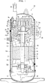
- Fig. 1 is a vertical cross-sectional view showing the entire structure of a scroll compressor in a first embodiment.
- the scroll compressor 1A in the first embodiment is structured by housing a compressing mechanism portion 3, a driving portion 4, a rotation shaft portion 5, and an oil supplying mechanism portion 6, in a airtight vessel 2.
- the compressing mechanism portion 3 has a structure including a revolving scroll 7, a fixed scroll 8, a frame 9 and a autorotation preventing mechanism 10.
- the revolving scroll 7 has a structure including a bedplate 7a, a revolving scroll body (revolving-side lap) 7b, a revolving scroll bearing portion 7c, and a plain bearing 7d.
- the bedplate 7a is substantially in a circular disk shape, provided with the scroll body 7b on the upper surface (one side) and the revolving scroll bearing portion 7c on the lower surface (the other side).
- the revolving scroll body 7b has a scroll shape and stands vertically on the one side of the bedplate 7a.
- the revolving scroll bearing portion 7c is vertically protruding to the other side (the side opposite to the revolving scroll body 7b) of the bedplate 7a.
- the revolving scroll bearing portion 7c has a cylindrical portion 7c1 extending in the axial direction (the upper-lower direction in the figure) and an annular portion 7c2 protruding outward in the radial direction in a flange shape at the tip end (lower end) of the cylindrical portion 7c1.
- the plain bearing 7d is fitted to the inside of the cylindrical portion 7c1 by pressure-fitting or the like to support the revolving scroll 7 to be slidable with respect to a crank shaft 12.
- the fixed scroll 8 has a structure including a bedplate 8a, a fixed scroll body (fixed side lap) 8b, a suctioning inlet 8c, and a discharging outlet 8d.
- the bedplate 8a is substantially in a circular disc shape and is provided with a bolt insertion hole 8a1 fastened by the later-described frame 9 and a bolt B, at an outer circumferential marginal portion.
- the fixed scroll body 8b is in a scroll shape, vertically stands on one side of the bedplate 8a, and is disposed such as to face the revolving scroll body 7b. In such a manner, the fixed scroll body 8b and the revolving scroll body 7b form a compression chamber Q1.
- the suctioning inlet 8c is formed on the outer circumferential side of the bedplate 8a and communicates with the outer portion of the airtight vessel 2 through a suction tube 23.
- the discharging outlet 8d is formed such as to penetrate through the bedplate 8a at the center along the axial direction, and communicates with the compression chamber Q1 and the outer portion of the compressing mechanism portion 3 inside the airtight vessel 2.
- the frame 9 has a structure including a fixed scroll fastening surface 9a that fastens the fixed scroll 8 by the bolt B, and a frame bearing portion 9b for housing a main bearing 13 (bearing) that rotatably supports the crank shaft 12.
- the autorotation preventing mechanism 10 is housed in the frame 9 and is engaged with the bedplate 7a, on the side opposite to the revolving scroll body 7b, so that the revolving scroll 7 moves with revolving, without autorotation relative to the fixed scroll 8.
- the autorotation preventing mechanism 10 is structured by a known method.
- the driving portion 4 has a structure including an electric motor 16 configured by a stator 14 and a rotor 15.
- the stator 14 is fixed to the inner wall surface of the airtight vessel 2, and the rotor 15 is fixed to the crank shaft 12.
- the electric motor 16 is driven by electrical input from a power source (not shown) through an electrical terminal 17 to apply a rotation force to the crank shaft 12.
- the rotation shaft portion 5 has a structure including the crank shaft 12, the main bearing 13, a sub-frame 18, a sub-bearing (rolling bearing) 19, a sub-bearing housing 20, and a balance weight 21.
- the crank shaft 12 has a structure including a main shaft portion 12a, a sub-shaft portion 12b, an eccentric pin portion 12c, a flange portion 12d, and a penetration hole 12e.
- the main shaft portion 12a is rotatably supported by the main bearing 13.
- the sub-shaft portion 12b is rotatably supported by the sub-bearing 19.
- the crank shaft 12 is connected with the rotor 15, between the main shaft portion 12a and the sub-shaft portion 12b.
- the eccentric pin portion 12c is arranged at the upper end (one end) of the main shaft portion 12a (crank shaft 12) such that the axis center of the eccentric pin portion 12c is eccentric from the axis center of the main shaft portion 12a.
- the eccentric pin portion 12c is engaged with the revolving scroll 7 through the plain bearing 7d.
- the flange portion 12d is formed at the lower portion of the eccentric pin portion 12c and has a diameter larger than those of the eccentric pin portion 12c and the main shaft portion 12a. Further, the axis center of the flange portion 12d and the center of the main shaft portion 12a agree with each other.
- the flange portion 12d is structured integrally with the eccentric pin portion 12c and the main shaft portion 12a.
- the integral structure refers to a structure obtained, for example, in such a manner that the crank shaft 12 is formed by cutting a single metal cylindrical material (ingot).
- the flange portion 12d is formed in a direction perpendicular to the axial direction G of the crank shaft 12, in other words, formed with high precision such that the upper surface 12d1 and the lower surface 12d2 of the flange portion 12d are perpendicular to the axial direction G (formed with precise perpendicularity).
- the flange portion 12d is provided with an oil passage 12f for communication between a high-pressure space Q2 between the upper surface 12d1 of the flange portion 12d and the revolving scroll 7 and a high-pressure space Q4 between the lower surface 12d2 of the flange portion 12d and the frame 9.
- the oil passage 12f communicates with oil accumulation 22 in the airtight vessel 2 through a pipe 41.
- the main bearing 13 is arranged by a plain bearing and fitted to the frame bearing portion 9b by press fitting or the like.
- the sub-frame 18 is arranged on the side opposite to the compressing mechanism portion 3 in the axial direction G of the crank shaft 12across the electric motor 16.
- the sub-frame 18 is fixed to the airtight vessel 2 by plug welding.
- the sub-bearing 19 is arranged in the sub-bearing housing 20 fixed to the sub-frame 18. Incidentally, the sub-frame 18 and the sub-bearing housing 20 may be integrally structured.
- the balance weight 21 is fitted to the flange portion 12d of the crank shaft 12 to have action in the direction where the balance weight 21 cancels imbalance caused by the revolution movement of the revolving scroll 7. Further, the balance weight 21 is fitted such as to protrude toward the outer circumferential side of the flange portion 12d. Still further, the balance weight 21 is fitted to the flange portion 12d by press fitting or the like.
- the oil supplying mechanism portion 6 is engaged with the lower end of the crank shaft 12. Using the rotation of the crank shaft 12, the oil supplying mechanism portion 6 suctions up oil from the oil accumulation 22 at the lower portion of the airtight vessel 2. The oil supplying mechanism portion 6 supplies the oil, through the penetration hole 12e formed through the crank shaft 12, to respective sliding portions of the compressing mechanism portion 3.
- fuel supplying means in general, a centrifugal pump or a volume variable pump is used.
- the scroll compressor 1A with such a structure operates as follows. By the rotation of the crank shaft 12 driven by the electric motor 16, the revolving scroll 7 moves with revolution. This provides a compression operation by decreasing the volume of the compression chamber Q1 which is mechanically structured by engagement between the revolving scroll body 7b and the fixed scroll body 8b.
- Operation fluid (refrigerant) is suctioned, from outside of the airtight vessel 2 through the suction tube 23 connected to the suctioning inlet 8c arranged at the airtight vessel 2, to the compression chamber Q1.
- the Operation fluid is then subjected to a compression process and then discharged from the discharging outlet 8d into the airtight vessel 2, and further discharged from a discharge pipe 24 arranged at the airtight vessel 2 to outside the airtight vessel 2.
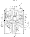
- Fig. 2 is a vertical cross-sectional view of the vicinity of the frame of the scroll compressor in the first embodiment.
- the frame 9 houses, inside thereof, the revolving scroll 7, the autorotation preventing mechanism 10, the main shaft portion 12a, the eccentric pin portion 12c, the flange portion 12d, the balance weight 21, a sealing member 25, and a thrust bearing 26.
- the sealing member 25 is arranged on the side of the upper surface 12d1 of the flange portion 12d, and seals the space between the revolving scroll 7 and the flange portion 12d, while sliding on the revolving scroll 7.
- the sealing member 25 can be any one having a sealability, and can be appropriately selected from one obtained by forming a resin member on a sliding surface (surface) of a metal base, one the entire of which is formed by a resin material, one made of metal, or the like.
- the thrust bearing 26 is arranged on the lower surface of the flange portion 12d and on the end surface 9c of the frame 9, slides on the flange portion 12d, and supports a load acting, in the axial direction, on the crank shaft 12.
- a resin material is preferably used on the both surfaces of the sliding surface sliding on the frame 9 and the sliding surface sliding on the flange portion 12d.
- the whole thrust bearing 26 may be made from a resin material, or the thrust bearing 26 may be formed by arranging resin material on the upper surface and the lower surface of a metallic piece.
- the back-pressure chamber Q3 has a pressure lower than the pressure of the high-pressure space Q2, which is a space adjacent to the crank shaft 12 and inside the sealing member 25.
- the back-pressure chamber Q3 optimizes the force lifting the revolving scroll 7 and increases the sealability of the compression chamber Q1, by a pressure adjusting mechanism (not shown) arranged on the fixed scroll 8 or the frame 9.
- a sliding surface 7e, which slides on the sealing member 25, of the revolving scroll 7 is provided with a throttle mechanism 30 that traverses the sealing member 25 in the radial direction by the revolution movement of the revolving scroll 7.
- the throttle mechanism 30 supplies oil by a differential pressure to the back-pressure chamber Q3 from the high-pressure space Q2, which is on the flange portion 12d side of the flange portion 12d and is a space adjacent to the crank shaft 12.
- the throttle mechanism 30 can be known means, such as a pocket groove, a slit, or the like.
- the flow of oil in the scroll compressor 1A structured in such a manner is as follows. That is, by the oil supplying mechanism portion 6 (see Fig. 1 ) fitted to the lower end of the crank shaft 12, oil accumulated at the lower end inside the airtight vessel 2 is suctioned up through the penetration hole 12e inside the crank shaft 12, and is supplied to the plain bearing 7d. Then, a part of the suctioned-up oil flows into the high-pressure space Q2 between the annular portion 7c2 of the revolving scroll 7 and the upper surface 12d1 of the flange portion 12d. The oil having arrived at the high-pressure space Q2 is supplied through the throttle mechanism 30 to the back-pressure chamber Q3.
- the oil supplied to the inside of the back-pressure chamber Q3 is supplied to the sliding portion between the revolving scroll 7 and the fixed scroll 8, and then discharged from the discharging outlet 8d.
- the oil discharged from the discharging outlet 8d moves through a gap (not shown) formed between the frame 9 and the airtight vessel 2, and discharged from the discharge pipe 24.
- the oil discharged from the discharging outlet 8d moves through gaps (not shown) formed at the frame 9, the electric motor 16, and the like to be returned to the lower end of the airtight vessel 2.
- the deflection of the crank shaft 12 itself also becomes large.
- the crank shaft 12 is deflected by both the centrifugal force of the revolving scroll 7 and the centrifugal force of the balance weight 21. If the centrifugal force of the balance weight 21 can be decreased, the deflection amount can also be reduced. For example, if it is assumed that the mass of the revolving scroll 7 is m, the radius is r, and the angular velocity is ⁇ , a centrifugal force F1 mr ⁇ 2 acts on the revolving scroll 7.
- a moment M1 that acts on the revolving scroll 7 is mr ⁇ 2 ⁇ L.
- the mass of the balance weight 21 is m', the radius is r', and the angular velocity is ⁇
- a centrifugal force F2 of m'r' ⁇ 2 acts on the balance weight 21.
- a moment M2 that acts on the balance weight 21 is m'r' ⁇ 2 ⁇ L'.
- a balance weight is a body separated from the crank shaft 12, and fitted to the crank shaft 12 by press fitting or the like. Consequently, it is difficult to attach a balance weight to the crank shaft 12 with high precision of perpendicularity to the axial direction of the crank shaft 12.
- the upper surface of a balance weight slides with a revolving scroll with each other through a thrust bearing. Accordingly, if the balance weight inclines with respect to the crank shaft, the revolving scroll also inclines with respect to the crank shaft.
- a balance weight is, in general, usually produced by a sinter process with a mold, which makes the surface roughness of a sintered product coarse. Accordingly, for sealing by a thrust bearing, it is necessary to finish the both of the upper and lower sliding surfaces of a balance weight, by machining additionally after a sinter process. Further, in most cases, a thrust bearing is provided with a rotation stopper portion (not shown) that is fixed to one component, and a material with excellent slidability is used for the sliding surface sliding on another component. In such a case, the sealability of the surface in contact with the fixed component decreases, which makes it impossible to ensure sealability between the back-pressure chamber and the space adjacent to the crank shaft.
- the sealability between high-pressure spaces Q2 and Q4, which are respectively on the inside of the sealing member 25 and the thrust bearing 26 (the inside along the radial direction), and the back-pressure chamber Q3, which is on the outside of them (outside in the radial direction), is improved so that the back-pressure chamber Q3 where the balance weight 21 is disposed can be made a space with little oil.
- the oil supplying mechanism portion 6 (see Fig. 1 ) is provided with the throttle mechanism 30 that adjusts (limits) the oil supply amount supplied from the high-pressure space Q2 to the back-pressure chamber Q3.
- the throttle mechanism 30 is formed, for example, on the surface where the sealing member 25 and the revolving scroll 7 (annular portion 7c2) face each other, by a groove in a slit shape that extends and straddles the sealing member 25 in the radial direction.
- the flange portion 12d is provided with the oil passage 12f penetrating through the flange portion 12d in the axial direction G, on the inner diameter side of the sealing member 25 and on the inner diameter side of the thrust bearing 26.
- the oil passage 12f it is possible to prevent excessive oil flows from the high-pressure space Q2 into the back-pressure chamber Q3.
- Fig. 3 is a vertical cross-sectional view of the vicinity of a frame of a scroll compressor in a second embodiment.
- the same symbols are given, and overlapping description will be omitted (likewise also in embodiments from a third embodiment and after).
- portions, not shown, are similar to those in the first embodiment (likewise also in embodiments from a third embodiment and after).
- a scroll compressor 1B in the second embodiment is one structured by adding a sealing member 27 to the scroll compressor 1A in the first embodiment.
- the sealing member 27 is formed by an O-ring or the like, and is housed in an annular groove 9d which is formed such as to face the lower surface of a thrust bearing 26 in a frame 9.
- the thrust bearing 26 is provided with a rotation prevention protrusion 26a for preventing rotation, and the frame 9 is provided with a recessed portion 9e with which the rotation stop protrusion 26a engages. Consequently, when a crank shaft 12 (flange portion 12d) rotates, the thrust bearing 26 is prevented from sliding and rotating with respect to the flange portion 12d with each other.
- Fig. 4 is a vertical cross-sectional view of the vicinity of a frame of a scroll compressor in a third embodiment.
- the scroll compressor 1C in the third embodiment is one structured by adding a second sealing member 31 to the scroll compressor 1A in the first embodiment.
- the second sealing member 31 is provided between the flange portion 12d and the frame 9, and on the outer diameter side of the thrust bearing 26.
- the member represented by symbol 25 is a first sealing member, which is structured similarly to the first sealing member 25 in the first embodiment.
- the second sealing member 31 can be any one that has sealability similarly to the first sealing member 25, and can be appropriately selected from one obtained by laminating a resin material on a sliding surface (surface) of a metal material, one that is entirely made from resin material, one that is entirely made from metal, and so on.
- the frame 9 houses therein a revolving scroll 7, a autorotation preventing mechanism 10, a main shaft portion 12a, an eccentric pin portion 12c, a flange portion 12d, a balance weight 21, the first sealing member 25, the second sealing member 31, and a thrust bearing 26.
- a portion formed by the flange portion 12d and the balance weight 21 corresponds to an outer circumferential protruding portion 32 of the crank shaft 12.
- the first sealing member 25 is mounted on the upper surface side 32a of the outer circumferential protruding portion 32 so that the first sealing member 25 seals between the revolving scroll 7 and the outer circumferential protruding portion 32, while sliding on the revolving scroll 7.
- the second sealing member 31 is mounted on the lower surface side 32b of the outer circumferential protruding portion 32 so that the second sealing member 31 seals between the outer circumferential protruding portion 32 and the frame 9, while sliding on either the outer circumferential protruding portion 32 or the frame 9.
- the second sealing member 31 is arranged on an annular groove 9f provided on the frame 9.
- the second sealing member 31 is arranged such as to be slightly movable in the axial direction G when the flange portion 12d and the thrust bearing 26 contact with each other.
- the second sealing member 31 is arranged such as to be slightly movable in the axial direction G when the flange portion 12d and the thrust bearing 26 contact with each other.
- the second sealing member 31 is arranged on the outer diameter side (the outside in the radial direction) of the thrust bearing 26.
- the second sealing member 31 is disposed on the flange portion 12d side of the outer circumferential protruding portion 32.
- a space which is partitioned by the first sealing member 25, the second sealing member 31, the revolving scroll 7, the frame 9, the fixed scroll 8, and the outer circumferential protruding portion 32, the space being located on the outer side of the first sealing member 25 and the second sealing member 31, is the back-pressure chamber Q3.
- the back-pressure chamber Q3 has a pressure lower than the pressure of the high-pressure space Q2, Q4, which are spaces adjacent to the crank shaft 12 and inside the first sealing member 25 and the second sealing member 31.
- a pressure adjusting mechanism (not shown) arranged on the 25 and the second sealing member 31.
- a pressure adjusting mechanism (not shown) arranged on the fixed scroll 8 or the frame 9 optimizes the force lifting the revolving scroll and increases the sealability of the compression chamber Q1.
- the sliding surface 7e, of the revolving scroll 7, sliding on the first sealing member 25 is provided with a throttle mechanism 30 (a pocket groove, a slit, or the like) that traverses the sealing member 25 in the radial direction by the revolution movement of the revolving scroll 7 to supply oil, by a differential pressure, from the high-pressure space Q2, which is at the upper portion of the outer circumferential protruding portion 32, to the back-pressure chamber Q3.
- the outer circumferential protruding portion 32 is provided with an oil passage 12f penetrating through the outer circumferential protruding portion 32 in the axial direction G.
- Oil having been supplied to oil accumulation 22 (see Fig. 1 ) by the oil supplying mechanism portion 6 (see Fig. 1 ) is supplied through a penetration hole 12e of the crank shaft 12 to a plain bearing 7d, and then arrives at the upper portion of an outer circumferential protruding portion 32.
- the oil having arrived at the upper portion of the outer circumferential protruding portion 32 is partially supplied through the throttle mechanism 30 to the back-pressure chamber Q3, and the rest arrives, through an oil passage 12f, at the lower portion of the outer circumferential protruding portion 32, gets disposed outside the frame 9 to be returned to the oil accumulation 22.
- a balance weight 21 is housed in the frame 9, and the balance weight 21 is mounted on the flange portion 12d adjacent to the revolving scroll 7. It is thereby possible to reduce the weight of the balance weight 21, reduce the deflection of the crank shaft 12, and thus improve the reliability of the scroll compressor 1C.
- the back-pressure chamber Q3, to which the balance weight 21 is fitted is made a space with little oil.
- the oil agitation loss caused by rotation of the balance weight 21, and the performance of the scroll compressor 1C can be improved.
- the third embodiment by providing the oil passage 12f, which penetrates in the axial direction G, on the inner diameter side (inner side in the radial direction) of the first sealing member 25 and on the inner diameter side of the second sealing member 31 and the thrust bearing 26, it is possible to prevent excessive oil flow from the high-pressure space Q2 and high-pressure space Q4 into the back-pressure chamber Q3. Yet, further, in the third embodiment, as the thrust bearing 26 is disposed on the inner diameter side (high-pressure space Q2 side) of the second sealing member 31, oil supply shortage can be prevented.
- Fig. 5 is a vertical cross-sectional view of the vicinity of a frame of a scroll compressor in a fourth embodiment.
- a second sealing member 31 is provided on an annular groove 12g formed on the flange portion 12d.
- Fig. 6 is a vertical cross-sectional view of the vicinity of a frame of a scroll compressor in a fifth embodiment.
- a second sealing member 31 is provided between the frame 9 and the balance weight 21.
- the frame 9 is provided with an annular groove 9g to which the second sealing member 31 is fitted, at a position facing the lower surface of the balance weight 21.
- an annular groove to which the second sealing member 31 is fitted may be arranged on the balance weight 21 side.
- the balance weight 21 is in a body separated from the flange portion 12d, and it is difficult to obtain a perpendicularity between the balance weight 21 and the crank shaft 12. Further, the balance weight 21 is, in general, usually produced by a sinter process with a mold, which makes the surface roughness of the sintered product coarse. In this situation, by arranging the second sealing member 31 between the balance weight 21 and the frame 9, it is possible to make the second sealing member 31 follow the inclination of the balance weight 21 and the deformation of the balance weight 21 to thereby ensure sealability, and prevent excessive flow of oil from the high-pressure spaces Q2 and Q4 into the back-pressure chamber Q3.
- Fig. 7 is a vertical cross-sectional view of the vicinity of a frame of a scroll compressor in a sixth embodiment.
- a second sealing member 31 is provided on the inner diameter side (inside in the radial direction) of the thrust bearing 26.
- the flange portion 12d is provided with the oil passage 12f on the inner diameter side of the sealing member 25 and the inner diameter side of the second sealing member 31 and the thrust bearing 26.
- the thrust bearing 26 by providing the thrust bearing 26 on the outer diameter side of the second sealing member 31, the thrust bearing 26 can be supported on the outer circumferential side of the flange portion 12d, and the crank shaft 12 can be stably supported.
- an integral structure refers to a structure where the crank shaft 12 is formed by cutting a single metal cylindrical material
- crank shaft 12 main shaft portion 12a
- balance weight 21
Landscapes
- Engineering & Computer Science (AREA)
- Mechanical Engineering (AREA)
- General Engineering & Computer Science (AREA)
- Rotary Pumps (AREA)
- Applications Or Details Of Rotary Compressors (AREA)
Abstract
Description
- The present invention relates to a scroll compressor.
- For a conventional scroll compressor, presented is an art in which a first thrust bearing is provided between a counter weight (balance weight) and a movable scroll (a revolving scroll), and a second thrust bearing is provided between the counter weight (balance weight) and a housing (frame) (for example, refer to Patent Document 1).
- Patent Document 1: Japanese Patent Application Laid-Open No.
H2-264175 - In a scroll compressor, a centrifugal force is caused on a crank shaft by the revolution movement of a revolving scroll, and a balance weight is fitted to the crank shaft to cancel imbalance caused by this centrifugal force. In general, at the closer position in the axial direction to the revolving scroll the balance weight is fitted, the lighter the balance weight can be arranged. Accordingly, the balance weight can be made light effectively by housing the balance weight inside a frame where the revolving scroll is housed.
- Further, for oil supply to the sliding portions of a bearing, a scroll and the like, in a scroll compressor, a pump mechanism is fitted to the lower end portion of a crank shaft, and an oil supply hole is provided inside the crank shaft, penetrating along the axial direction. Oil supplied by this pump mechanism is supplied, inside the frame, to the respective sliding portions represented by a plain bearing (revolution bearing), a scroll portion, and the like.
- However, in the art disclosed by
Patent Document 1, as the load of the crank shaft is supported actively between the balance weight and the frame, sealing between the revolving scroll and the balance weight is weakened, and oil excessively flows into a back-pressure chamber. Consequently, in a case of housing a balance weight in the inside of a frame, there was a problem that the balance weight rotationally moves in the space excessively containing oil so that loss is caused by agitation of the oil, and thus the performance is decreased. - The present invention solves the above conventional problem, and an object of the invention is to provide a scroll compressor enabling improvement of the performance by reducing the amount of oil that flows into a back-pressure chamber.
- An aspect of the present invention provides a scroll compressor, including:
- a crank shaft including an eccentric pin portion eccentric from an axial center;
- a revolving scroll having a scroll shape on a bedplate and connected to the eccentric pin portion;
- a fixed scroll having a scroll shape that engages with the scroll shape of the revolving scroll;
- an autorotation preventing mechanism that prevents the revolving scroll from autorotating;
- a frame that houses the revolving scroll and the autorotation preventing mechanism, rotatably supports the crank shaft with a bearing, and fixes the fixed scroll, wherein the crank shaft includes a flange portion having a larger diameter than a diameter of the eccentric pin portion and arranged at a lower portion of the eccentric pin portion;
- a balance weight that is mounted on the flange portion to cancel imbalance caused by rotational movement of the eccentric pin portion and revolution movement of the revolving scroll;
- a sealing member that provides sealing between the revolving scroll and the flange portion; and
- a thrust bearing provided between the frame and the flange portion. Advantageous Effect of the Invention
- According to the invention, it is possible to provide a scroll compressor enabling improvement of the performance by decreasing the amount of oil that flows into a back-pressure chamber.
-
-
Fig. 1 is a vertical cross-sectional view showing the entire structure of a scroll compressor in a first embodiment; -
Fig. 2 is a vertical cross-sectional view of the vicinity of the frame of the scroll compressor in the first embodiment; -
Fig. 3 is a vertical cross-sectional view of the vicinity of a frame of a scroll compressor in a second embodiment; -
Fig. 4 is a vertical cross-sectional view of the vicinity of a frame of a scroll compressor in a third embodiment; -
Fig. 5 is a vertical cross-sectional view of the vicinity of a frame of a scroll compressor in a fourth embodiment; -
Fig. 6 is a vertical cross-sectional view of the vicinity of a frame of a scroll compressor in a fifth embodiment; and -
Fig. 7 is a vertical cross-sectional view of the vicinity of a frame of a scroll compressor in a sixth embodiment. - In the following, embodiments for carrying out the present invention (hereinafter, referred to as 'embodiment') will be described in detail, referring to the drawings, as appropriate. In the following, a vertical type scroll compressor with a vertical axial direction (upper-lower direction) will be described as an example, however, the invention can also be applied to a horizontal type scroll compressor with a horizontal axis direction.
-
Fig. 1 is a vertical cross-sectional view showing the entire structure of a scroll compressor in a first embodiment. - As shown in
Fig. 1 , thescroll compressor 1A in the first embodiment is structured by housing a compressing mechanism portion 3, adriving portion 4, arotation shaft portion 5, and an oilsupplying mechanism portion 6, in aairtight vessel 2. - The compressing mechanism portion 3 has a structure including a
revolving scroll 7, afixed scroll 8, aframe 9 and aautorotation preventing mechanism 10. - The revolving
scroll 7 has a structure including abedplate 7a, a revolving scroll body (revolving-side lap) 7b, a revolvingscroll bearing portion 7c, and a plain bearing 7d. - The
bedplate 7a is substantially in a circular disk shape, provided with thescroll body 7b on the upper surface (one side) and the revolvingscroll bearing portion 7c on the lower surface (the other side). The revolvingscroll body 7b has a scroll shape and stands vertically on the one side of thebedplate 7a. The revolvingscroll bearing portion 7c is vertically protruding to the other side (the side opposite to the revolvingscroll body 7b) of thebedplate 7a. The revolvingscroll bearing portion 7c has a cylindrical portion 7c1 extending in the axial direction (the upper-lower direction in the figure) and an annular portion 7c2 protruding outward in the radial direction in a flange shape at the tip end (lower end) of the cylindrical portion 7c1. The plain bearing 7d is fitted to the inside of the cylindrical portion 7c1 by pressure-fitting or the like to support the revolvingscroll 7 to be slidable with respect to acrank shaft 12. - The
fixed scroll 8 has a structure including abedplate 8a, a fixed scroll body (fixed side lap) 8b, a suctioninginlet 8c, and adischarging outlet 8d. - The
bedplate 8a is substantially in a circular disc shape and is provided with a bolt insertion hole 8a1 fastened by the later-describedframe 9 and a bolt B, at an outer circumferential marginal portion. The fixedscroll body 8b is in a scroll shape, vertically stands on one side of thebedplate 8a, and is disposed such as to face the revolvingscroll body 7b. In such a manner, thefixed scroll body 8b and the revolvingscroll body 7b form a compression chamber Q1. The suctioninginlet 8c is formed on the outer circumferential side of thebedplate 8a and communicates with the outer portion of theairtight vessel 2 through asuction tube 23. Thedischarging outlet 8d is formed such as to penetrate through thebedplate 8a at the center along the axial direction, and communicates with the compression chamber Q1 and the outer portion of the compressing mechanism portion 3 inside theairtight vessel 2. - The
frame 9 has a structure including a fixedscroll fastening surface 9a that fastens thefixed scroll 8 by the bolt B, and aframe bearing portion 9b for housing a main bearing 13 (bearing) that rotatably supports thecrank shaft 12. - The
autorotation preventing mechanism 10 is housed in theframe 9 and is engaged with thebedplate 7a, on the side opposite to the revolvingscroll body 7b, so that the revolving scroll 7 moves with revolving, without autorotation relative to thefixed scroll 8. Incidentally, theautorotation preventing mechanism 10 is structured by a known method. - The
driving portion 4 has a structure including anelectric motor 16 configured by a stator 14 and arotor 15. - In the
electric motor 16, the stator 14 is fixed to the inner wall surface of theairtight vessel 2, and therotor 15 is fixed to thecrank shaft 12. Theelectric motor 16 is driven by electrical input from a power source (not shown) through anelectrical terminal 17 to apply a rotation force to thecrank shaft 12. - The
rotation shaft portion 5 has a structure including thecrank shaft 12, the main bearing 13, asub-frame 18, a sub-bearing (rolling bearing) 19, asub-bearing housing 20, and abalance weight 21. - The
crank shaft 12 has a structure including amain shaft portion 12a, asub-shaft portion 12b, aneccentric pin portion 12c, aflange portion 12d, and apenetration hole 12e. - The
main shaft portion 12a is rotatably supported by the main bearing 13. Thesub-shaft portion 12b is rotatably supported by thesub-bearing 19. Thecrank shaft 12 is connected with therotor 15, between themain shaft portion 12a and thesub-shaft portion 12b. - The
eccentric pin portion 12c is arranged at the upper end (one end) of themain shaft portion 12a (crank shaft 12) such that the axis center of theeccentric pin portion 12c is eccentric from the axis center of themain shaft portion 12a. Theeccentric pin portion 12c is engaged with the revolvingscroll 7 through theplain bearing 7d. - The
flange portion 12d is formed at the lower portion of theeccentric pin portion 12c and has a diameter larger than those of theeccentric pin portion 12c and themain shaft portion 12a. Further, the axis center of theflange portion 12d and the center of themain shaft portion 12a agree with each other. - The
flange portion 12d is structured integrally with theeccentric pin portion 12c and themain shaft portion 12a. Herein, the integral structure refers to a structure obtained, for example, in such a manner that thecrank shaft 12 is formed by cutting a single metal cylindrical material (ingot). In such a manner, theflange portion 12d is formed in a direction perpendicular to the axial direction G of thecrank shaft 12, in other words, formed with high precision such that the upper surface 12d1 and the lower surface 12d2 of theflange portion 12d are perpendicular to the axial direction G (formed with precise perpendicularity). - The
flange portion 12d is provided with anoil passage 12f for communication between a high-pressure space Q2 between the upper surface 12d1 of theflange portion 12d and the revolvingscroll 7 and a high-pressure space Q4 between the lower surface 12d2 of theflange portion 12d and theframe 9. Theoil passage 12f communicates withoil accumulation 22 in theairtight vessel 2 through apipe 41. - The
main bearing 13 is arranged by a plain bearing and fitted to theframe bearing portion 9b by press fitting or the like. Thesub-frame 18 is arranged on the side opposite to the compressing mechanism portion 3 in the axial direction G of the crank shaft 12across theelectric motor 16. Thesub-frame 18 is fixed to theairtight vessel 2 by plug welding. The sub-bearing 19 is arranged in thesub-bearing housing 20 fixed to thesub-frame 18. Incidentally, thesub-frame 18 and thesub-bearing housing 20 may be integrally structured. - The
balance weight 21 is fitted to theflange portion 12d of thecrank shaft 12 to have action in the direction where thebalance weight 21 cancels imbalance caused by the revolution movement of the revolvingscroll 7. Further, thebalance weight 21 is fitted such as to protrude toward the outer circumferential side of theflange portion 12d. Still further, thebalance weight 21 is fitted to theflange portion 12d by press fitting or the like. - At the lower portion of the
airtight vessel 2, the oil supplyingmechanism portion 6 is engaged with the lower end of thecrank shaft 12. Using the rotation of thecrank shaft 12, the oil supplyingmechanism portion 6 suctions up oil from theoil accumulation 22 at the lower portion of theairtight vessel 2. The oil supplyingmechanism portion 6 supplies the oil, through thepenetration hole 12e formed through thecrank shaft 12, to respective sliding portions of the compressing mechanism portion 3. As fuel supplying means, in general, a centrifugal pump or a volume variable pump is used. - The
scroll compressor 1A with such a structure operates as follows. By the rotation of thecrank shaft 12 driven by theelectric motor 16, the revolvingscroll 7 moves with revolution. This provides a compression operation by decreasing the volume of the compression chamber Q1 which is mechanically structured by engagement between the revolvingscroll body 7b and thefixed scroll body 8b. Operation fluid (refrigerant) is suctioned, from outside of theairtight vessel 2 through thesuction tube 23 connected to thesuctioning inlet 8c arranged at theairtight vessel 2, to the compression chamber Q1. The Operation fluid is then subjected to a compression process and then discharged from the dischargingoutlet 8d into theairtight vessel 2, and further discharged from adischarge pipe 24 arranged at theairtight vessel 2 to outside theairtight vessel 2. -
Fig. 2 is a vertical cross-sectional view of the vicinity of the frame of the scroll compressor in the first embodiment. - As shown in
Fig. 2 , theframe 9 houses, inside thereof, the revolvingscroll 7, theautorotation preventing mechanism 10, themain shaft portion 12a, theeccentric pin portion 12c, theflange portion 12d, thebalance weight 21, a sealingmember 25, and athrust bearing 26. - The sealing
member 25 is arranged on the side of the upper surface 12d1 of theflange portion 12d, and seals the space between the revolvingscroll 7 and theflange portion 12d, while sliding on the revolvingscroll 7. The sealingmember 25 can be any one having a sealability, and can be appropriately selected from one obtained by forming a resin member on a sliding surface (surface) of a metal base, one the entire of which is formed by a resin material, one made of metal, or the like. - The
thrust bearing 26 is arranged on the lower surface of theflange portion 12d and on theend surface 9c of theframe 9, slides on theflange portion 12d, and supports a load acting, in the axial direction, on thecrank shaft 12. - In order to improve the sealability, for the
thrust bearing 26, a resin material is preferably used on the both surfaces of the sliding surface sliding on theframe 9 and the sliding surface sliding on theflange portion 12d. Incidentally, the whole thrust bearing 26 may be made from a resin material, or thethrust bearing 26 may be formed by arranging resin material on the upper surface and the lower surface of a metallic piece. - The space on the outer side of the sealing
member 25, the space being partitioned by the above-described sealingmember 25, thethrust bearing 26, the revolvingscroll 7, the fixedscroll 8, theframe 9, and theflange portion 12d, forms a back-pressure chamber Q3. The back-pressure chamber Q3 has a pressure lower than the pressure of the high-pressure space Q2, which is a space adjacent to thecrank shaft 12 and inside the sealingmember 25. The back-pressure chamber Q3 optimizes the force lifting the revolvingscroll 7 and increases the sealability of the compression chamber Q1, by a pressure adjusting mechanism (not shown) arranged on the fixedscroll 8 or theframe 9. A slidingsurface 7e, which slides on the sealingmember 25, of the revolvingscroll 7 is provided with athrottle mechanism 30 that traverses the sealingmember 25 in the radial direction by the revolution movement of the revolvingscroll 7. Thethrottle mechanism 30 supplies oil by a differential pressure to the back-pressure chamber Q3 from the high-pressure space Q2, which is on theflange portion 12d side of theflange portion 12d and is a space adjacent to thecrank shaft 12. Thethrottle mechanism 30 can be known means, such as a pocket groove, a slit, or the like. - The flow of oil in the
scroll compressor 1A structured in such a manner is as follows. That is, by the oil supplying mechanism portion 6 (seeFig. 1 ) fitted to the lower end of thecrank shaft 12, oil accumulated at the lower end inside theairtight vessel 2 is suctioned up through thepenetration hole 12e inside thecrank shaft 12, and is supplied to theplain bearing 7d. Then, a part of the suctioned-up oil flows into the high-pressure space Q2 between the annular portion 7c2 of the revolvingscroll 7 and the upper surface 12d1 of theflange portion 12d. The oil having arrived at the high-pressure space Q2 is supplied through thethrottle mechanism 30 to the back-pressure chamber Q3. The rest of the oil supplied into the high-pressure space Q2 moves through theoil passage 12f and arrives at the high-pressure space Q4 between the lower surface 12d2 of theflange portion 12d and theframe 9, moves in thepipe 41 to be disposed outside theframe 9, and returns to the oil accumulation 22 (seeFig. 1 ). - The oil supplied to the inside of the back-pressure chamber Q3 is supplied to the sliding portion between the revolving
scroll 7 and the fixedscroll 8, and then discharged from the dischargingoutlet 8d. The oil discharged from the dischargingoutlet 8d moves through a gap (not shown) formed between theframe 9 and theairtight vessel 2, and discharged from thedischarge pipe 24. The oil discharged from the dischargingoutlet 8d moves through gaps (not shown) formed at theframe 9, theelectric motor 16, and the like to be returned to the lower end of theairtight vessel 2. - Herein, if the centrifugal force of the revolving
scroll 7 is large, the deflection of thecrank shaft 12 itself also becomes large. Thecrank shaft 12 is deflected by both the centrifugal force of the revolvingscroll 7 and the centrifugal force of thebalance weight 21. If the centrifugal force of thebalance weight 21 can be decreased, the deflection amount can also be reduced. For example, if it is assumed that the mass of the revolvingscroll 7 is m, the radius is r, and the angular velocity is ω, a centrifugal force F1 mrω2 acts on the revolvingscroll 7. Accordingly, if the distance from the rotation center of the crank shaft 12 (main shaft portion 12a) to the rotation center of the revolvingscroll 7 is represented by L, a moment M1 that acts on the revolvingscroll 7 is mrω2 × L. On the other hand, if it is assumed that the mass of thebalance weight 21 is m', the radius is r', and the angular velocity is ω, a centrifugal force F2 of m'r'ω2 acts on thebalance weight 21. Accordingly, if the distance from the rotation center of the crank shaft 12 (main shaft portion 12a) to the rotation center of thebalance weight 21 is represented by L', a moment M2 that acts on thebalance weight 21 is m'r'ω2 × L'. In other words, if the distance L' can be made small, the mass m' of thebalance weight 21 can be made small (reduction in weight), and the centrifugal force of thebalance weight 21 can be made small. - In this situation, on the
scroll compressor 1A in the first embodiment, by housing thebalance weight 21 in theframe 9 and fitting it to theflange portion 12d, it is possible to make thebalance weight 21 closer to the axial direction G of thecrank shaft 12, which attains reduction in weight of thebalance weight 21. In such a manner, by reducing the weight of thebalance weight 21, the deflection of thecrank shaft 12 can be reduced so that the performance of thescroll compressor 1A can be improved. - Incidentally, in general, a balance weight is a body separated from the
crank shaft 12, and fitted to thecrank shaft 12 by press fitting or the like. Consequently, it is difficult to attach a balance weight to thecrank shaft 12 with high precision of perpendicularity to the axial direction of thecrank shaft 12. Further, in a conventional art, the upper surface of a balance weight slides with a revolving scroll with each other through a thrust bearing. Accordingly, if the balance weight inclines with respect to the crank shaft, the revolving scroll also inclines with respect to the crank shaft. As the revolving scroll and the crank shaft are engaged by a plain bearing (revolution bearing), such an inclination sometimes causes a contact between surfaces only on one side, resulting in a decrease in the reliability of the scroll compressor. Further, a balance weight is, in general, usually produced by a sinter process with a mold, which makes the surface roughness of a sintered product coarse. Accordingly, for sealing by a thrust bearing, it is necessary to finish the both of the upper and lower sliding surfaces of a balance weight, by machining additionally after a sinter process. Further, in most cases, a thrust bearing is provided with a rotation stopper portion (not shown) that is fixed to one component, and a material with excellent slidability is used for the sliding surface sliding on another component. In such a case, the sealability of the surface in contact with the fixed component decreases, which makes it impossible to ensure sealability between the back-pressure chamber and the space adjacent to the crank shaft. - In this situation, in the first embodiment, by structuring a seal portion with the sealing
member 25 and thethrust bearing 26, the sealability between high-pressure spaces Q2 and Q4, which are respectively on the inside of the sealingmember 25 and the thrust bearing 26 (the inside along the radial direction), and the back-pressure chamber Q3, which is on the outside of them (outside in the radial direction), is improved so that the back-pressure chamber Q3 where thebalance weight 21 is disposed can be made a space with little oil. In such a manner, it is possible to decrease the oil agitation loss caused by the rotation of thebalance weight 21, and improve the performance of thescroll compressor 1A. Incidentally, as the load of thecrank shaft 12 acts downward in the axial direction G, it is not necessary to actively receive the load by the upper surface 12d1 side of theflange portion 12d, and it is not necessary to provide the thrust bearing 26 on nor under theflange portion 12d. - Further, the oil supplying mechanism portion 6 (see
Fig. 1 ) is provided with thethrottle mechanism 30 that adjusts (limits) the oil supply amount supplied from the high-pressure space Q2 to the back-pressure chamber Q3. Thethrottle mechanism 30 is formed, for example, on the surface where the sealingmember 25 and the revolving scroll 7 (annular portion 7c2) face each other, by a groove in a slit shape that extends and straddles the sealingmember 25 in the radial direction. Thus, it is possible to prevent shortage of oil supply to the back-pressure chamber Q3, and prevent increase of friction force and burning on the sliding surface between the revolvingscroll 7 and the fixedscroll 8. - Further, in the first embodiment, the
flange portion 12d is provided with theoil passage 12f penetrating through theflange portion 12d in the axial direction G, on the inner diameter side of the sealingmember 25 and on the inner diameter side of thethrust bearing 26. In such a manner, by providing theoil passage 12f, it is possible to prevent excessive oil flows from the high-pressure space Q2 into the back-pressure chamber Q3. -
Fig. 3 is a vertical cross-sectional view of the vicinity of a frame of a scroll compressor in a second embodiment. Incidentally, to elements similar to those in the first embodiment, the same symbols are given, and overlapping description will be omitted (likewise also in embodiments from a third embodiment and after). Further, inFig. 3 , portions, not shown, are similar to those in the first embodiment (likewise also in embodiments from a third embodiment and after). - As shown in
Fig. 3 , ascroll compressor 1B in the second embodiment is one structured by adding a sealingmember 27 to thescroll compressor 1A in the first embodiment. The sealingmember 27 is formed by an O-ring or the like, and is housed in anannular groove 9d which is formed such as to face the lower surface of athrust bearing 26 in aframe 9. - Further, the
thrust bearing 26 is provided with arotation prevention protrusion 26a for preventing rotation, and theframe 9 is provided with a recessedportion 9e with which the rotation stopprotrusion 26a engages. Consequently, when a crank shaft 12 (flange portion 12d) rotates, thethrust bearing 26 is prevented from sliding and rotating with respect to theflange portion 12d with each other. - In such a manner, by providing the
rotation preventing protrusion 26a to the thrust bearing 26 to thereby obtain a structure that prevents the thrust bearing 26 from sliding on theframe 9 and the sealingmember 27, and it is thereby possible to use an inexpensive component such as an O-ring for a static seal. Further, adopting the above-described structure, the sealability between theframe 9 and the lower surface 12d2 of theflange portion 12d can be improved, compared with the first embodiment. Incidentally, other effects are the same as those in the first embodiment. - Incidentally, although, in the second embodiment, a case of providing the
rotation preventing protrusion 26a to thethrust bearing 26 was described as an example, it is also possible, in contrast, to provide a rotation preventing protrusion to theframe 9, and provide the thrust bearing 26 with a recessed portion for recession-protrusion engagement with the rotation preventing protrusion. -
Fig. 4 is a vertical cross-sectional view of the vicinity of a frame of a scroll compressor in a third embodiment. - As shown in
Fig. 4 , thescroll compressor 1C in the third embodiment is one structured by adding asecond sealing member 31 to thescroll compressor 1A in the first embodiment. Thesecond sealing member 31 is provided between theflange portion 12d and theframe 9, and on the outer diameter side of thethrust bearing 26. Incidentally, the member represented bysymbol 25 is a first sealing member, which is structured similarly to the first sealingmember 25 in the first embodiment. Thesecond sealing member 31 can be any one that has sealability similarly to the first sealingmember 25, and can be appropriately selected from one obtained by laminating a resin material on a sliding surface (surface) of a metal material, one that is entirely made from resin material, one that is entirely made from metal, and so on. - In the
scroll compressor 1C, theframe 9 houses therein a revolvingscroll 7, aautorotation preventing mechanism 10, amain shaft portion 12a, aneccentric pin portion 12c, aflange portion 12d, abalance weight 21, the first sealingmember 25, the second sealingmember 31, and athrust bearing 26. Herein, a portion formed by theflange portion 12d and thebalance weight 21 corresponds to an outercircumferential protruding portion 32 of thecrank shaft 12. - The
first sealing member 25 is mounted on theupper surface side 32a of the outercircumferential protruding portion 32 so that the first sealingmember 25 seals between the revolvingscroll 7 and the outercircumferential protruding portion 32, while sliding on the revolvingscroll 7. - The
second sealing member 31 is mounted on thelower surface side 32b of the outercircumferential protruding portion 32 so that the second sealingmember 31 seals between the outercircumferential protruding portion 32 and theframe 9, while sliding on either the outercircumferential protruding portion 32 or theframe 9. In the third embodiment, the second sealingmember 31 is arranged on anannular groove 9f provided on theframe 9. - Further, the second sealing
member 31 is arranged such as to be slightly movable in the axial direction G when theflange portion 12d and the thrust bearing 26 contact with each other. Thus, when theflange portion 12d and the thrust bearing 26 contact with each other, it is possible to support the load in the axial direction G by the thrust bearing 26 only, without allowing the load in the axial direction G of thecrank shaft 12 to act on the second sealingmember 31. Accordingly, abrasion of the second sealingmember 31 can be reduced. - The
second sealing member 31 is arranged on the outer diameter side (the outside in the radial direction) of thethrust bearing 26. Thesecond sealing member 31 is disposed on theflange portion 12d side of the outercircumferential protruding portion 32. - In the
scroll compressor 1C with such a structure, a space, which is partitioned by the first sealingmember 25, the second sealingmember 31, the revolvingscroll 7, theframe 9, the fixedscroll 8, and the outercircumferential protruding portion 32, the space being located on the outer side of the first sealingmember 25 and the second sealingmember 31, is the back-pressure chamber Q3. The back-pressure chamber Q3 has a pressure lower than the pressure of the high-pressure space Q2, Q4, which are spaces adjacent to thecrank shaft 12 and inside the first sealingmember 25 and the second sealingmember 31. A pressure adjusting mechanism (not shown) arranged on the 25 and the second sealingmember 31. A pressure adjusting mechanism (not shown) arranged on the fixedscroll 8 or theframe 9 optimizes the force lifting the revolving scroll and increases the sealability of the compression chamber Q1. - The sliding
surface 7e, of the revolvingscroll 7, sliding on the first sealingmember 25 is provided with a throttle mechanism 30 (a pocket groove, a slit, or the like) that traverses the sealingmember 25 in the radial direction by the revolution movement of the revolvingscroll 7 to supply oil, by a differential pressure, from the high-pressure space Q2, which is at the upper portion of the outercircumferential protruding portion 32, to the back-pressure chamber Q3. The outercircumferential protruding portion 32 is provided with anoil passage 12f penetrating through the outercircumferential protruding portion 32 in the axial direction G. - Oil having been supplied to oil accumulation 22 (see
Fig. 1 ) by the oil supplying mechanism portion 6 (seeFig. 1 ) is supplied through apenetration hole 12e of thecrank shaft 12 to aplain bearing 7d, and then arrives at the upper portion of an outercircumferential protruding portion 32. The oil having arrived at the upper portion of the outercircumferential protruding portion 32 is partially supplied through thethrottle mechanism 30 to the back-pressure chamber Q3, and the rest arrives, through anoil passage 12f, at the lower portion of the outercircumferential protruding portion 32, gets disposed outside theframe 9 to be returned to theoil accumulation 22. - In the third embodiment with such a structure, a
balance weight 21 is housed in theframe 9, and thebalance weight 21 is mounted on theflange portion 12d adjacent to the revolvingscroll 7. It is thereby possible to reduce the weight of thebalance weight 21, reduce the deflection of thecrank shaft 12, and thus improve the reliability of thescroll compressor 1C. - Further, in the third embodiment, by providing the first sealing
member 25 and the second sealingmember 31, the back-pressure chamber Q3, to which thebalance weight 21 is fitted, is made a space with little oil. Thus, it is possible to decrease the oil agitation loss caused by rotation of thebalance weight 21, and the performance of thescroll compressor 1C can be improved. - Still further, in the third embodiment, by providing the
oil passage 12f, which penetrates in the axial direction G, on the inner diameter side (inner side in the radial direction) of the first sealingmember 25 and on the inner diameter side of the second sealingmember 31 and thethrust bearing 26, it is possible to prevent excessive oil flow from the high-pressure space Q2 and high-pressure space Q4 into the back-pressure chamber Q3. Yet, further, in the third embodiment, as thethrust bearing 26 is disposed on the inner diameter side (high-pressure space Q2 side) of the second sealingmember 31, oil supply shortage can be prevented. -
Fig. 5 is a vertical cross-sectional view of the vicinity of a frame of a scroll compressor in a fourth embodiment. - Instead of the structure in a third embodiment, where the second sealing
member 31 is provided on theannular groove 9f formed on theframe 9 side, in ascroll compressor 1D in the fourth embodiment, as shown inFig. 5 , asecond sealing member 31 is provided on anannular groove 12g formed on theflange portion 12d. With this structure, effects similar to those in the third embodiment can be obtained, -
Fig. 6 is a vertical cross-sectional view of the vicinity of a frame of a scroll compressor in a fifth embodiment. - Instead of the structure, in the third embodiment, where the second sealing
member 31 is provided between theframe 9 and theflange portion 12d (crank shaft 12), in the fifth embodiment, as shown inFig. 6 , asecond sealing member 31 is provided between theframe 9 and thebalance weight 21. - The
frame 9 is provided with anannular groove 9g to which the second sealingmember 31 is fitted, at a position facing the lower surface of thebalance weight 21. Incidentally, an annular groove to which the second sealingmember 31 is fitted may be arranged on thebalance weight 21 side. - Incidentally, the
balance weight 21 is in a body separated from theflange portion 12d, and it is difficult to obtain a perpendicularity between thebalance weight 21 and thecrank shaft 12. Further, thebalance weight 21 is, in general, usually produced by a sinter process with a mold, which makes the surface roughness of the sintered product coarse. In this situation, by arranging the second sealingmember 31 between thebalance weight 21 and theframe 9, it is possible to make the second sealingmember 31 follow the inclination of thebalance weight 21 and the deformation of thebalance weight 21 to thereby ensure sealability, and prevent excessive flow of oil from the high-pressure spaces Q2 and Q4 into the back-pressure chamber Q3. -
Fig. 7 is a vertical cross-sectional view of the vicinity of a frame of a scroll compressor in a sixth embodiment. - Instead of the structure, in the third embodiment, where the second sealing
member 31 is provided on the outer diameter side (the outside in the radial direction) of thethrust bearing 26, in the sixth embodiment, as shown inFig. 7 , asecond sealing member 31 is provided on the inner diameter side (inside in the radial direction) of thethrust bearing 26. - Further, the
flange portion 12d is provided with theoil passage 12f on the inner diameter side of the sealingmember 25 and the inner diameter side of the second sealingmember 31 and thethrust bearing 26. - In the sixth embodiment with such a structure, by providing the thrust bearing 26 on the outer diameter side of the second sealing
member 31, thethrust bearing 26 can be supported on the outer circumferential side of theflange portion 12d, and thecrank shaft 12 can be stably supported. - The present invention is not limited to the above-described embodiments, and can be variously modified and changed within a scope without departing from the spirit of the invention. For example, in any of the first to sixth embodiments, cases, where the
flange portion 12d as the outercircumferential protruding portion 32 and thebalance weight 21 are separately structured. were described as examples, however, theflange portion 12d and thebalance weight 21 may be integrally structured. Incidentally, an integral structure refers to a structure where thecrank shaft 12 is formed by cutting a single metal cylindrical material - (ingot). Thus, it is possible to precisely form the perpendicularity between the crank shaft 12 (
main shaft portion 12a) and thebalance weight 21. -
- 1A, 1B, 1C, 1D, 1E, 1F .. scroll compressor
- 2 .. airtight vessel
- 7 .. revolving scroll
- 7a .. bedplate
- 8 .. fixed scroll
- 9 .. frame
- 10 .. autorotation preventing mechanism
- 12 .. crank shaft
- 12c .. eccentric pin portion
- 12d .. flange portion
- 12f .. oil passage
- 13 .. main bearing (bearing)
- 21 .. balance weight
- 25 .. sealing member, first sealing member
- 26 .. thrust bearing
- 30 .. throttle mechanism
- 31 .. second sealing member
- 32 .. outer circumferential protruding portion
- G .. axial direction
- Q1 .. compression chamber
- Q2, Q4 ..high-pressure space
- Q3 .. back-pressure chamber
Claims (11)
- A scroll compressor, comprising:a crank shaft including an eccentric pin portion eccentric from an axial center;a revolving scroll having a scroll shape on a bedplate and connected to the eccentric pin portion;a fixed scroll having a scroll shape that engages with the scroll shape of the revolving scroll;an autorotation preventing mechanism that prevents the revolving scroll from autorotating;a frame that houses the revolving scroll and the autorotation preventing mechanism, rotatably supports the crank shaft with a bearing, and fixes the fixed scroll, wherein the crank shaft includes a flange portion having a larger diameter than a diameter of the eccentric pin portion and arranged at a lower portion of the eccentric pin portion;a balance weight that is mounted on the flange portion to cancel imbalance caused by rotational movement of the eccentric pin portion and revolution movement of the revolving scroll;a sealing member that provides sealing between the revolving scroll and the flange portion; anda thrust bearing provided between the frame and the flange portion.
- The scroll compressor according to claim 1,wherein a space adjacent to the flange portion is partitioned, by the sealing member and the thrust bearing, in a high-pressure space on an inner diameter side of the sealing member and the thrust bearing, and a back-pressure chamber on an outer diameter side of the sealing member and the thrust bearing,and wherein the revolving scroll includes a throttle mechanism that limits oil supply from the high-pressure space to the back-pressure chamber.
- The scroll compressor according to claim 1,wherein the flange portion includes an oil passage that penetrates through the flange portion in an axial direction of the crank shaft, on an inner diameter side of the sealing member and the thrust slide bearing.
- The scroll compressor according to claim 1,wherein the thrust bearing is mounted on the frame, in a state of being prevented from rotating with respect to the frame,the scroll compressor further comprising a sealing member that provides sealing between the thrust bearing and the frame.
- A scroll compressor, comprising:a crank shaft having an eccentric pin eccentric from an axial center;a revolving scroll having a scroll shape on a bedplate and connected to the eccentric pin;a fixed scroll having a scroll shape that engages with the scroll shape of the revolving scroll;an autorotation preventing mechanism that prevents the revolving scroll from autorotating;a frame that houses the revolving scroll and the autorotation preventing mechanism, supports the crank shaft such as to be rotatable by a bearing, and fixes the fixed scroll;a balance weight that is mounted on the crank shaft to cancel imbalance caused by rotational movement of the eccentric pin and revolution movement of the revolving scroll,wherein the crank shaft includes an outer circumferential portion structured with a flange portion with a diameter larger than a diameter of the eccentric pin and the balance weight protruding to the back-pressure chamber, the outer circumferential portion being arranged at a lower portion of the eccentric pin;a first sealing member that provides sealing between the revolving scroll and the outer circumferential protruding portion; anda second sealing member that provides sealing between the frame and the outer circumferential protruding portion.
- The scroll compressor according to claim 5,wherein a space adjacent to the flange portion is partitioned, by the first sealing member and the second sealing member, in a high-pressure space on an inner diameter side of the first sealing member and the second sealing member, and a back-pressure chamber on an outer diameter side of the first sealing member and the second sealing member,and wherein the revolving scroll includes a throttle mechanism that limits oil supply from the high-pressure space to the back-pressure chamber.
- The scroll compressor according to claim 5,wherein the second sealing member is disposed between the balance weight and the frame.
- The scroll compressor according to claim 5, comprising:a thrust bearing between the frame and the outer circumferential protruding portion,wherein the second sealing member is disposed on an outer diameter side of the thrust bearing.
- The scroll compressor according to claim 8,wherein the second sealing member is disposed on an inner diameter side of the thrust bearing.
- The scroll compressor according to claim 8,wherein the flange portion includes an oil passage that penetrates through the flange portion in an axial direction of the crank shaft, on an inner diameter side of the first sealing member and on an inner diameter side of the second sealing member and the thrust bearing.
- The scroll compressor according to either claim 1 or 8,wherein the thrust bearing uses a resin material at a sliding portion sliding on the frame and a sliding portion sliding on the crank shaft.
Applications Claiming Priority (2)
| Application Number | Priority Date | Filing Date | Title |
|---|---|---|---|
| JP2015101619A JP6611468B2 (en) | 2015-05-19 | 2015-05-19 | Scroll compressor |
| PCT/IB2016/052759 WO2016185336A1 (en) | 2015-05-19 | 2016-05-13 | Scroll compressor |
Publications (2)
| Publication Number | Publication Date |
|---|---|
| EP3299625A1 true EP3299625A1 (en) | 2018-03-28 |
| EP3299625A4 EP3299625A4 (en) | 2018-12-26 |
Family
ID=57319524
Family Applications (1)
| Application Number | Title | Priority Date | Filing Date |
|---|---|---|---|
| EP16795971.7A Withdrawn EP3299625A4 (en) | 2015-05-19 | 2016-05-13 | Scroll compressor |
Country Status (6)
| Country | Link |
|---|---|
| US (1) | US10718329B2 (en) |
| EP (1) | EP3299625A4 (en) |
| JP (1) | JP6611468B2 (en) |
| KR (1) | KR101947305B1 (en) |
| CN (1) | CN107709783B (en) |
| WO (1) | WO2016185336A1 (en) |
Families Citing this family (8)
| Publication number | Priority date | Publication date | Assignee | Title |
|---|---|---|---|---|
| JP6715722B2 (en) * | 2016-07-29 | 2020-07-01 | 日立ジョンソンコントロールズ空調株式会社 | Scroll compressor |
| JP2019019772A (en) * | 2017-07-19 | 2019-02-07 | 日立ジョンソンコントロールズ空調株式会社 | Scroll compressor |
| CN109404289B (en) * | 2017-08-16 | 2024-05-14 | 谷轮环境科技(苏州)有限公司 | Rotary machine |
| DE102019124516A1 (en) * | 2019-09-12 | 2021-03-18 | Hanon Systems | Positioning arrangement |
| WO2022021663A1 (en) * | 2020-07-30 | 2022-02-03 | 艾默生环境优化技术(苏州)有限公司 | Compressor |
| CN112727756B (en) * | 2021-01-21 | 2024-12-27 | 珠海格力节能环保制冷技术研究中心有限公司 | Scroll compressor, air conditioner and vehicle |
| CN117072442A (en) * | 2022-05-10 | 2023-11-17 | 苏州英华特涡旋技术股份有限公司 | Controllable deformation main bearing seat and compressor including the main bearing seat |
| CN117249086A (en) | 2022-06-10 | 2023-12-19 | 日立江森自控空调有限公司 | a compressor |
Family Cites Families (26)
| Publication number | Priority date | Publication date | Assignee | Title |
|---|---|---|---|---|
| JPS5979086A (en) | 1982-10-27 | 1984-05-08 | Hitachi Ltd | scroll fluid machine |
| US4875838A (en) | 1988-05-12 | 1989-10-24 | Tecumseh Products Company | Scroll compressor with orbiting scroll member biased by oil pressure |
| US4884955A (en) | 1988-05-12 | 1989-12-05 | Tecumseh Products Company | Scroll compressor having oil-actuated compliance mechanism |
| JPH02264175A (en) | 1989-04-04 | 1990-10-26 | Sanden Corp | Scroll type compressor |
| JPH0826761B2 (en) | 1989-12-25 | 1996-03-21 | 三菱電機株式会社 | Scroll fluid machinery |
| US5137437A (en) | 1990-01-08 | 1992-08-11 | Hitachi, Ltd. | Scroll compressor with improved bearing |
| JP2712914B2 (en) * | 1991-03-04 | 1998-02-16 | 三菱電機株式会社 | Scroll compressor |
| JPH07217555A (en) | 1994-01-27 | 1995-08-15 | Sanyo Electric Co Ltd | Scroll type unlubricated fluid machinery |
| KR0133408B1 (en) * | 1994-05-17 | 1998-04-28 | 구자홍 | Axial Leakage Prevention Device of Scroll Compressor |
| JPH08326676A (en) * | 1995-06-05 | 1996-12-10 | Matsushita Electric Ind Co Ltd | Compressor for refrigerator |
| JP3473448B2 (en) | 1998-10-05 | 2003-12-02 | 松下電器産業株式会社 | Compressor and method of assembling the same |
| JP2001012369A (en) * | 1999-06-29 | 2001-01-16 | Sanden Corp | Compressor |
| JP2001329967A (en) | 2000-05-24 | 2001-11-30 | Toyota Industries Corp | Seal structure of scroll type compressor |
| JP2003021060A (en) | 2001-07-10 | 2003-01-24 | Toyota Industries Corp | Compressor, and method and tool for balancing compressor |
| JP2003227476A (en) | 2002-02-05 | 2003-08-15 | Matsushita Electric Ind Co Ltd | Air supply device |
| CN1281868C (en) | 2002-08-27 | 2006-10-25 | Lg电子株式会社 | Vortex compressor |
| JP3843333B2 (en) | 2002-09-11 | 2006-11-08 | 株式会社日立製作所 | Scroll fluid machinery |
| JP4394380B2 (en) * | 2003-06-03 | 2010-01-06 | 日立アプライアンス株式会社 | Scroll fluid machinery |
| KR100608663B1 (en) * | 2004-02-19 | 2006-08-08 | 엘지전자 주식회사 | Back Pressure Sealing Device of High Pressure Scroll Compressor |
| KR100912515B1 (en) * | 2007-09-12 | 2009-08-19 | 학교법인 두원학원 | Scroll compressor with back pressure seal |
| CN201288666Y (en) | 2008-09-19 | 2009-08-12 | 广州日立压缩机有限公司 | Structure for axial push stopping apparatus of cyclone compressor |
| JP5331738B2 (en) * | 2010-03-16 | 2013-10-30 | 日立アプライアンス株式会社 | Scroll fluid machinery |
| CN201687707U (en) | 2010-04-19 | 2010-12-29 | 上海化工研究院 | A scroll supercharger with a magnetic sealing device |
| FR2969226B1 (en) | 2010-12-16 | 2013-01-11 | Danfoss Commercial Compressors | SPIRAL REFRIGERATING COMPRESSOR |
| JP5380482B2 (en) | 2011-03-08 | 2014-01-08 | 日立アプライアンス株式会社 | Scroll compressor |
| CN102562589A (en) | 2012-03-21 | 2012-07-11 | 南通市红星空压机配件制造有限公司 | Vortex type air compressor |
-
2015
- 2015-05-19 JP JP2015101619A patent/JP6611468B2/en active Active
-
2016
- 2016-05-13 US US15/574,534 patent/US10718329B2/en active Active
- 2016-05-13 CN CN201680028271.5A patent/CN107709783B/en active Active
- 2016-05-13 WO PCT/IB2016/052759 patent/WO2016185336A1/en not_active Ceased
- 2016-05-13 EP EP16795971.7A patent/EP3299625A4/en not_active Withdrawn
- 2016-05-13 KR KR1020177033194A patent/KR101947305B1/en active Active
Also Published As
| Publication number | Publication date |
|---|---|
| CN107709783A (en) | 2018-02-16 |
| US20180128269A1 (en) | 2018-05-10 |
| KR20180019524A (en) | 2018-02-26 |
| EP3299625A4 (en) | 2018-12-26 |
| US10718329B2 (en) | 2020-07-21 |
| JP2016217219A (en) | 2016-12-22 |
| WO2016185336A1 (en) | 2016-11-24 |
| CN107709783B (en) | 2020-03-10 |
| JP6611468B2 (en) | 2019-11-27 |
| KR101947305B1 (en) | 2019-02-12 |
Similar Documents
| Publication | Publication Date | Title |
|---|---|---|
| US10718329B2 (en) | Scroll compressor | |
| EP2762726B1 (en) | Scroll compressor | |
| JP5581440B2 (en) | Scroll compressor | |
| EP2762727B1 (en) | Scroll compressor | |
| JPWO2013171957A1 (en) | Electric compressor | |
| CN109642570B (en) | scroll compressor | |
| WO2021124500A1 (en) | Scroll compressor | |
| WO2014132771A1 (en) | Scroll compressor | |
| US9945378B2 (en) | Scroll compressor | |
| CN100376800C (en) | fluid compressor | |
| JP4842110B2 (en) | Scroll compressor | |
| JP6207828B2 (en) | Scroll compressor | |
| EP3130805A1 (en) | Scroll compressor | |
| JP4888427B2 (en) | Compressor | |
| US10294943B2 (en) | Scroll compressor with a lubrication arrangement | |
| EP3951180A1 (en) | Scroll compressor | |
| WO2016016917A1 (en) | Scroll compressor | |
| US20050207926A1 (en) | Scroll compressor | |
| JP2010121583A (en) | Hermetic electric compressor | |
| JP2015042858A (en) | Hermetic scroll compressor | |
| JP2021046811A (en) | Horizontal scroll compressor | |
| JP2021025502A (en) | Scroll compressor | |
| JP2015038328A (en) | Compressor | |
| JP2006070711A (en) | Scroll compressor | |
| JP2006063943A (en) | Scroll compressor |
Legal Events
| Date | Code | Title | Description |
|---|---|---|---|
| STAA | Information on the status of an ep patent application or granted ep patent |
Free format text: STATUS: THE INTERNATIONAL PUBLICATION HAS BEEN MADE |
|
| PUAI | Public reference made under article 153(3) epc to a published international application that has entered the european phase |
Free format text: ORIGINAL CODE: 0009012 |
|
| STAA | Information on the status of an ep patent application or granted ep patent |
Free format text: STATUS: REQUEST FOR EXAMINATION WAS MADE |
|
| 17P | Request for examination filed |
Effective date: 20171219 |
|
| AK | Designated contracting states |
Kind code of ref document: A1 Designated state(s): AL AT BE BG CH CY CZ DE DK EE ES FI FR GB GR HR HU IE IS IT LI LT LU LV MC MK MT NL NO PL PT RO RS SE SI SK SM TR |
|
| AX | Request for extension of the european patent |
Extension state: BA ME |
|
| DAV | Request for validation of the european patent (deleted) | ||
| DAX | Request for extension of the european patent (deleted) | ||
| A4 | Supplementary search report drawn up and despatched |
Effective date: 20181128 |
|
| RIC1 | Information provided on ipc code assigned before grant |
Ipc: F04C 27/00 20060101ALI20181123BHEP Ipc: F04C 29/02 20060101ALI20181123BHEP Ipc: F04C 18/02 20060101AFI20181123BHEP |
|
| GRAP | Despatch of communication of intention to grant a patent |
Free format text: ORIGINAL CODE: EPIDOSNIGR1 |
|
| STAA | Information on the status of an ep patent application or granted ep patent |
Free format text: STATUS: GRANT OF PATENT IS INTENDED |
|
| INTG | Intention to grant announced |
Effective date: 20201117 |
|
| STAA | Information on the status of an ep patent application or granted ep patent |
Free format text: STATUS: THE APPLICATION IS DEEMED TO BE WITHDRAWN |
|
| 18D | Application deemed to be withdrawn |
Effective date: 20210330 |