JP6207828B2 - Scroll compressor - Google Patents
Scroll compressor Download PDFInfo
- Publication number
- JP6207828B2 JP6207828B2 JP2012240486A JP2012240486A JP6207828B2 JP 6207828 B2 JP6207828 B2 JP 6207828B2 JP 2012240486 A JP2012240486 A JP 2012240486A JP 2012240486 A JP2012240486 A JP 2012240486A JP 6207828 B2 JP6207828 B2 JP 6207828B2
- Authority
- JP
- Japan
- Prior art keywords
- pressure chamber
- back pressure
- oil
- scroll
- compressor
- Prior art date
- Legal status (The legal status is an assumption and is not a legal conclusion. Google has not performed a legal analysis and makes no representation as to the accuracy of the status listed.)
- Expired - Fee Related
Links
- 230000006835 compression Effects 0.000 claims description 34
- 238000007906 compression Methods 0.000 claims description 34
- 230000002093 peripheral effect Effects 0.000 claims description 5
- 239000003921 oil Substances 0.000 description 57
- 239000003507 refrigerant Substances 0.000 description 21
- 239000010687 lubricating oil Substances 0.000 description 16
- 238000012986 modification Methods 0.000 description 9
- 230000004048 modification Effects 0.000 description 9
- 239000012530 fluid Substances 0.000 description 6
- 238000004519 manufacturing process Methods 0.000 description 2
- 238000000034 method Methods 0.000 description 2
- 230000002265 prevention Effects 0.000 description 2
- 238000007599 discharging Methods 0.000 description 1
- 238000009434 installation Methods 0.000 description 1
- 238000003825 pressing Methods 0.000 description 1
Images
Landscapes
- Rotary Pumps (AREA)
Description
本発明は、スクロール型圧縮機に関するものである。 The present invention relates to a scroll compressor.
スクロール型圧縮機において、固定スクロールと、固定スクロールに対して公転旋回運動する旋回スクロールは、互いに噛み合っている。スクロール型圧縮機が流体を圧縮するとき、圧縮反力によって、旋回スクロールにスラスト荷重が作用し、旋回スクロールが固定スクロールから離れようとする。そのため、旋回スクロールの端板に対して流体の圧縮空間とは反対側の面(以下「背面」という。)から、旋回スクロールを支持する必要がある。旋回スクロールを支持する方法として、旋回スクロールの背面側に背圧室を形成し、背圧室の圧力を高めることによって、旋回スクロールを固定スクロール側に押し付ける方法がある(例えば、特許文献1及び2など)。 In the scroll compressor, the fixed scroll and the orbiting scroll that revolves around the fixed scroll mesh with each other. When the scroll compressor compresses the fluid, a thrust load acts on the orbiting scroll due to the compression reaction force, and the orbiting scroll tends to separate from the fixed scroll. Therefore, it is necessary to support the orbiting scroll from the surface opposite to the fluid compression space (hereinafter referred to as “rear surface”) with respect to the end plate of the orbiting scroll. As a method of supporting the orbiting scroll, there is a method of pressing the orbiting scroll against the fixed scroll side by forming a back pressure chamber on the back side of the orbiting scroll and increasing the pressure of the back pressure chamber (for example, Patent Documents 1 and 2). Such).
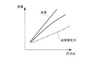
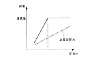
背圧室内は、必要背圧力よりも高く維持される必要がある。但し、背圧室内が高圧になり過ぎると旋回スクロールの公転旋回運動が妨げられてしまう。特許文献1では、背圧室内が高圧になり過ぎないように、背圧室と低圧の吸入室の間に差圧式制御弁を設けることが開示されている。差圧式制御弁は、図8の破線で示すように、圧縮機の圧力比が一定以上を超えて、背圧室内が高圧になった時に、背圧室と吸入室とを連通させることによって、背圧室の圧力を目標圧で安定するように作動する。なお、特許文献2では、背圧室の調圧について、開示されていない。 The back pressure chamber needs to be maintained higher than the required back pressure. However, if the pressure in the back pressure chamber becomes too high, the revolving orbiting motion of the orbiting scroll will be hindered. Patent Document 1 discloses that a differential pressure control valve is provided between the back pressure chamber and the low pressure suction chamber so that the back pressure chamber does not become too high. As shown by the broken line in FIG. 8, when the pressure ratio of the compressor exceeds a certain level and the back pressure chamber becomes high pressure, the differential pressure control valve communicates the back pressure chamber and the suction chamber, It operates to stabilize the pressure in the back pressure chamber at the target pressure. Note that Patent Document 2 does not disclose the pressure regulation of the back pressure chamber.
背圧室の調圧のため、特許文献1のように差圧式制御弁を使用すると、スクロール型圧縮機の内部に一定の設置スペースを確保する必要があるため、装置の小型化が図りにくい。また、差圧式制御弁を使用した場合、背圧室内が目標圧に到達するまでは、必要な背圧力に比べて、背圧室が過度に高くなってしまう(図8参照)。 When a differential pressure control valve is used as in Patent Document 1 to regulate the back pressure chamber, it is necessary to secure a certain installation space inside the scroll compressor, and thus it is difficult to reduce the size of the apparatus. Further, when the differential pressure control valve is used, the back pressure chamber becomes excessively higher than the required back pressure until the back pressure chamber reaches the target pressure (see FIG. 8).
本発明は、このような事情に鑑みてなされたものであって、別部材を設けることなく、背圧室を供給圧力に応じて、背圧室内の圧力を調整することが可能なスクロール型圧縮機を提供することを目的とする。 The present invention has been made in view of such circumstances, and is a scroll-type compression capable of adjusting the pressure in the back pressure chamber according to the supply pressure without providing a separate member. The purpose is to provide a machine.
上記課題を解決するために、本発明のスクロール型圧縮機は以下の手段を採用する。
すなわち、本発明に係るスクロール型圧縮機は、固定スクロール及び前記固定スクロールに対して公転旋回運動する旋回スクロールを有する圧縮部と、前記圧縮部に面する背圧室と、オイルセパレータから油が供給される油溜め部と、前記油溜め部から前記背圧室へ前記油を供給する油供給路と、前記圧縮部に回転力を伝達する回転軸と、前記回転軸に形成され、前記背圧室と低圧室を結び、前記油供給路よりも圧力損失が高い油排出路とを備え、前記油排出路は、前記回転軸の外周面に螺旋状に形成された溝を有している。
In order to solve the above problems, the scroll compressor of the present invention employs the following means.
That is, the scroll compressor according to the present invention supplies oil from a fixed scroll and a compression section having a turning scroll that revolves around the fixed scroll, a back pressure chamber facing the compression section, and an oil separator. An oil reservoir, an oil supply passage for supplying the oil from the oil reservoir to the back pressure chamber, a rotary shaft for transmitting a rotational force to the compression unit, and the rotary shaft. It signed a chamber and a low pressure chamber, and a pressure loss is high oil discharge passage than the oil supply passage, the oil discharge passage, that has a groove formed in a spiral shape on the outer peripheral surface of the rotary shaft.
この構成によれば、高圧側の油が、油供給路を経由して、油溜め部から背圧室へ供給され、背圧室内に供給された油が、油排出路を経由して、低圧側の低圧室に排出される。油排出路は、油供給路よりも圧力損失が高いことから、油が背圧室に満たされ、背圧室が高圧に維持される。その結果、背圧室側から旋回スクロールを固定スクロール側へ押し付けることができる。また、背圧室に供給される油の圧力に応じて、背圧室から低圧室に常に油が排出されることから、背圧室内の圧力が過度に高くなることを防止できる。 According to this configuration, the oil on the high pressure side is supplied from the oil reservoir to the back pressure chamber via the oil supply passage, and the oil supplied to the back pressure chamber is low pressure via the oil discharge passage. To the low pressure chamber on the side. Since the oil discharge path has a higher pressure loss than the oil supply path, the oil is filled in the back pressure chamber and the back pressure chamber is maintained at a high pressure. As a result, the orbiting scroll can be pressed from the back pressure chamber side to the fixed scroll side. Further, since the oil is always discharged from the back pressure chamber to the low pressure chamber according to the pressure of the oil supplied to the back pressure chamber, it is possible to prevent the pressure in the back pressure chamber from becoming excessively high.
また、本発明に係るスクロール型圧縮機は、固定スクロール及び前記固定スクロールに対して公転旋回運動する旋回スクロールを有する圧縮部と、前記圧縮部に面する背圧室と、前記旋回スクロールの端板のうち前記圧縮部内側の高圧領域に形成された開口部と前記背圧室側に形成された開口部とを結ぶ第1ガス流路、及び前記端板のうち前記圧縮部内側の中間圧領域に形成された開口部と前記背圧室側に形成された開口部とを結ぶ第2ガス流路と、前記背圧室と低圧室を結ぶ第3ガス流路とを備え、前記第1ガス流路、前記第2ガス流路及び前記第3ガス流路は、それぞれ、同じ前記背圧室に直接接続している。 The scroll compressor according to the present invention includes a fixed scroll and a compression portion having a turning scroll that revolves around the fixed scroll, a back pressure chamber facing the compression portion, and an end plate of the turning scroll. A first gas flow path connecting an opening formed in the high pressure region inside the compression portion and an opening formed on the back pressure chamber side, and an intermediate pressure region inside the compression portion of the end plate And a third gas flow path connecting the back pressure chamber and the low pressure chamber, and a first gas flow path connecting the opening formed on the back pressure chamber side and the opening formed on the back pressure chamber side. The flow path, the second gas flow path, and the third gas flow path are each directly connected to the same back pressure chamber.
この構成によれば、圧縮部で高圧に圧縮された高圧ガスと、圧縮部で高圧に達する前の中間圧まで圧縮された中間圧ガスと、低圧室における低圧ガスとが背圧室内でバランスする。そして、背圧室内でバランスした圧力によって、背圧室側から旋回スクロールを固定スクロール側へ押し付けることができる。圧縮部における圧縮比の高低に応じて、背圧室内でバランスする圧力が変化することから、背圧室内の圧力が過度に高くなることを防止できる。 According to this configuration, the high pressure gas compressed to a high pressure in the compression portion, the intermediate pressure gas compressed to the intermediate pressure before reaching the high pressure in the compression portion, and the low pressure gas in the low pressure chamber balance in the back pressure chamber. . Then, the orbiting scroll can be pressed from the back pressure chamber side to the fixed scroll side by the pressure balanced in the back pressure chamber. Since the pressure balanced in the back pressure chamber changes according to the compression ratio in the compression section, the pressure in the back pressure chamber can be prevented from becoming excessively high.
また、本発明の参考例に係るスクロール型圧縮機は、固定スクロール及び前記固定スクロールに対して公転旋回運動する旋回スクロールを有する圧縮部と、前記圧縮部に面する背圧室と、前記旋回スクロールの端板のうち前記圧縮部内側の高圧領域に形成された開口部及び前記旋回スクロールの端板のうち前記圧縮部内側の中間圧領域に形成された開口部と前記背圧室側に形成された開口部とを結ぶ第4ガス流路と、前記背圧室と低圧室を結ぶ第3ガス流路とを備える。 A scroll compressor according to a reference example of the present invention includes a compression unit having a fixed scroll and a turning scroll that revolves around the fixed scroll, a back pressure chamber facing the compression unit, and the turning scroll. An opening formed in a high pressure region inside the compression portion of the end plate and an opening formed in an intermediate pressure region inside the compression portion of the end plate of the orbiting scroll and the back pressure chamber side. A fourth gas flow path connecting the opening and a third gas flow path connecting the back pressure chamber and the low pressure chamber.
この構成によれば、圧縮部で高圧に圧縮された高圧ガス及び圧縮部で高圧に達する前の中間圧まで圧縮された中間圧ガスが混合したガスの圧力と、低圧室における低圧ガスとが背圧室内でバランスする。そして、背圧室内でバランスした圧力によって、背圧室側から旋回スクロールを固定スクロール側へ押し付けることができる。圧縮部における圧縮比の高低に応じて、背圧室内でバランスする圧力が変化することから、背圧室内の圧力が過度に高くなることを防止できる。 According to this configuration, the pressure of the gas mixed with the high pressure gas compressed to a high pressure in the compression section and the intermediate pressure gas compressed to the intermediate pressure before reaching the high pressure in the compression section and the low pressure gas in the low pressure chamber are reduced. Balance in the pressure chamber. Then, the orbiting scroll can be pressed from the back pressure chamber side to the fixed scroll side by the pressure balanced in the back pressure chamber. Since the pressure balanced in the back pressure chamber changes according to the compression ratio in the compression section, the pressure in the back pressure chamber can be prevented from becoming excessively high.
上記発明において、オイルセパレータから油が供給される油溜め部と、前記油溜め部から前記背圧室へ前記油を供給する油供給路と、前記圧縮部に回転力を伝達する回転軸と、前記回転軸に形成され、前記背圧室と低圧室を結び、前記油供給路よりも圧力損失が高い油排出路とを更に備えてもよい。 In the above invention, an oil reservoir part to which oil is supplied from an oil separator, an oil supply path for supplying the oil from the oil reservoir part to the back pressure chamber, a rotating shaft that transmits a rotational force to the compression part, An oil discharge passage formed on the rotating shaft, connecting the back pressure chamber and the low pressure chamber and having a pressure loss higher than that of the oil supply passage may be further provided.
本発明によれば、別部材を設けることなく、背圧室を供給圧力に応じて、背圧室内の圧力を調整することができる。 According to the present invention, the pressure in the back pressure chamber can be adjusted according to the supply pressure without providing a separate member.
以下に、本発明に係る実施形態について、図面を参照して説明する。
[第1実施形態]
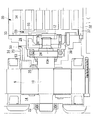
以下、本発明の第1実施形態について、図1を用いて説明する。
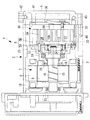
本実施形態に係るスクロール型圧縮機1は、図1に示すように、ハウジング3,4からなる密閉容器2を備えている。これらのハウジング3,4は、互いに接合されて一体化されることにより密閉容器2を構成している。
Embodiments according to the present invention will be described below with reference to the drawings.
[First Embodiment]
Hereinafter, a first embodiment of the present invention will be described with reference to FIG.
As shown in FIG. 1, the scroll compressor 1 according to this embodiment includes a sealed container 2 including
ハウジング3の中央部には、ステータ8及びモータロータ9からなる電動モータ7がハウジング3に対して固定設置されている。回転軸(シャフト)10は、一端部分がフロント軸受22に支持され、他端部分が圧縮機30に連結されるように延設されており、中間部分には、電動モータ7のモータロータ9が焼き嵌めによって結合されている。
フロント軸受22は、密閉容器2に対する回転軸10の支持部材であり、ハウジング3に対して固定設置されている。
An
The front bearing 22 is a support member of the
圧縮機30は、電動モータ7の他端部分側に設けられる。この圧縮機30は、主軸受部材23に固定された主軸受24と、ハウジング3に対し固定設置される固定スクロール32と、回転軸10の他端に設けられているクランクピン10Aに嵌合されるとともに、固定スクロール32に噛合されて圧縮室を形成し、回転軸10の回転によって固定スクロール32の周りに公転旋回駆動される旋回スクロール33等から構成される。旋回スクロール33は、円板状の端板37と、端板37の一面側に立設された渦巻き状ラップ34と、端板37の他面側に設けられたボス状のドライブ軸受38などからなる。
The
主軸受部材23は、図1に示すように、ハウジング3に対して固定され、主軸受24は、密閉容器2に対する回転軸10の支持部材である。圧縮機30の固定スクロール32は、主軸受部材23を介してハウジング3の他端側にて固定設置されている。圧縮機30は、低圧室14から冷媒を吸入し圧縮した後、ハウジング4に形成されている吐出室36内に冷媒を吐き出し、外部へと送出する。
As shown in FIG. 1, the main bearing
圧縮機30は、図1ではピン5Aとリング5Bで形成される自転阻止機構5を有する。ピン5Aとリング5Bによって、旋回スクロール33は、固定されている固定スクロール32に対して自転が阻止された状態で公転旋回運動を行う。
バランスウエイト13は、ドライブブッシュ12に固定され、回転による遠心力によって、旋回スクロール33が公転旋回することによって生じる遠心力と均衡を図る。
The
The
主軸受部材23の主軸受24よりも電動モータ7側には、シャフトシール25が設けられる。シャフトシール25は、回転軸10と主軸受部材23との間から流体が漏れることを防止する。これにより、旋回スクロール33の端板37と主軸受部材23との間には、背圧室26が形成される。
A
圧縮機30で圧縮された流体(例えば冷媒)は、固定スクロール32の中心部に設けられた吐出孔39から、ハウジング4内に形成された吐出室36内に吐出される。そして、圧縮された流体は、オイルセパレータ41で冷媒に含まれている潤滑油が分離された後、吐出ポート部42から外部へ供給される。オイルセパレータ41で分離された潤滑油は、ハウジング4に形成された油溜め室43に送られる。油溜め室43内の潤滑油は、流体の吐出圧によって高圧となっている。潤滑油は、冷媒に含まれて、圧縮機30内部に供給されたとき、旋回スクロール33の公転旋回運動を滑らかにさせる。
A fluid (for example, a refrigerant) compressed by the
油供給管44は、固定スクロール32の内部に管状に形成される。油供給管44は、油溜め室43と背圧室26を結ぶ。潤滑油は、油溜め室43から油供給管44を通過して、背圧室26に供給される。その結果、背圧室26内は、高圧の潤滑油で満たされる。
The
回転軸10には、油排出管15が形成される。油排出管15は、油供給管44よりも圧力損失が高く、背圧室26と低圧室14を結ぶ。これにより、背圧室26内の潤滑油の圧力に応じて、背圧室26から低圧室14へ潤滑油が排出される。油排出管15は、例えば、背圧室26側では、例えば、クランクピン10Aの軸心と、回転軸10の軸心とを含むように、クランクピン10Aや回転軸10の内部に管状に形成される。そして、油排出管15は、低圧室14側では、モータロータ9が結合されている辺りで、回転軸10の外周面に螺旋状の溝が形成される。溝が形成されることによって、回転軸10とモータロータ9との間で潤滑油が通過可能な管路が形成される。このように、油排出管15の距離を長くすることによって、油排出管15の圧力損失が高くなる。
An
上述したとおり、本実施形態によれば、油排出管15は、油供給管44よりも圧力損失が高いことから、潤滑油が背圧室26に満たされ、背圧室26が高圧に維持される。その結果、背圧室26側から旋回スクロール33を固定スクロール32側へ押し付けることができる。
また、背圧室26に供給される潤滑油の圧力に応じて、背圧室26から低圧室14に常に潤滑油が排出されることから、背圧室26内の圧力が過度に高くなることを防止できる。すなわち、図7の実線で示すように、圧縮機30の圧力比が高くなるにつれて、徐々に背圧室26内の背圧力も高まり、従来(図7の破線)のように、必要背圧力に比べて背圧室26内の圧力が過度に高くなることがない。
As described above, according to the present embodiment, since the
Further, since the lubricating oil is always discharged from the
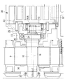
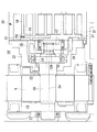
次に、図2を参照して、本実施形態の変形例について説明する。
上述した例では、背圧室26と低圧室14を結ぶ油排出管15は、モータロータ9と回転軸10が焼き嵌められている部分において、回転軸10の外周面に溝が形成されるとした。一方、本変形例の油排出管16は、図2に示すように、クランクピン10Aや回転軸10の軸心を含む部分において、回転軸10の背圧室26から低圧室14側まで貫通して形成される。
Next, a modification of the present embodiment will be described with reference to FIG.
In the example described above, the
油排出管15において、回転軸10の一端側の開口部から、螺旋ピン17が管路内部に挿入される。螺旋ピン17は、回転軸10に形成された管路の内径とほぼ同一の外径を有し、外周面に螺旋状の溝が形成されている。これにより、管路の内面と螺旋ピン17の外面との間で潤滑油が通過可能な管路が形成される。このように、本変形例に係る油排出管16によっても、油排出管16の距離を長くすることができ、油排出管16の圧力損失が高くなる。
In the
[第2実施形態]
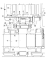
次に、本発明の第2実施形態について、図3を用いて説明する。
スクロール型圧縮機1の構成は、上述した第1実施形態と同様であり、重複する説明は省略する。
第2実施形態では、圧縮機30によって圧縮された高圧及び中間圧の冷媒ガスを背圧室26に供給することによって、背圧室26内部の圧力が必要背圧力を超えるようにする。また、背圧室26の冷媒ガスが低圧室14へ排出されることによって、背圧室26内の圧力が過度に高くなることを防止できる。
[Second Embodiment]
Next, a second embodiment of the present invention will be described with reference to FIG.
The configuration of the scroll compressor 1 is the same as that of the first embodiment described above, and redundant description is omitted.
In the second embodiment, the high-pressure and intermediate-pressure refrigerant gas compressed by the
高圧ガス路51は、旋回スクロール33の端板37の中央付近に貫通して形成され、圧縮機30の内部と背圧室26を結ぶ。
中間圧ガス路52は、一端側の開口部が旋回スクロール33の端板37の半径方向中間部分であって、渦巻き状ラップ34が設けられていない部分に形成され、他端側の開口部が背圧室26に面して形成される。これにより、中間圧ガス路52は、圧縮機30の内部と背圧室26を結び、圧縮機30内部で圧縮され中間圧まで上昇した冷媒ガスを背圧室26へ供給する。
なお、中間圧ガス路52の製造上、端板37の側面から管路を形成する必要があり、この場合、端板37の側面に形成された開口部にイモネジ59を挿入して、開口部を塞ぐ必要がある。これにより、端板37内部に複雑な形状の中間圧ガス路52を形成できる。
The high-
The intermediate
In order to manufacture the intermediate
低圧ガス路53は、主軸受部材23において、一端側の開口部が背圧室26に面して形成され、他端側の開口部が低圧室14に面して形成される。これにより、低圧ガス路53は、背圧室26と低圧室14を結び、背圧室26内の冷媒ガスを低圧室14へ排出する。低圧ガス路53についても、製造上、主軸受部材23の側面に形成された開口部にイモネジ59を挿入して、開口部を塞ぐ。
In the
上述したとおり、本実施形態によれば、圧縮機30で高圧に圧縮された高圧ガスと、圧縮機30で高圧に達する前の中間圧に圧縮された中間圧ガスと、低圧室14における低圧ガスとが背圧室26内でバランスする。そして、背圧室26内でバランスした圧力によって、背圧室26側から旋回スクロール33を固定スクロール32側へ押し付けることができる。圧縮機30における圧縮比の高低に応じて、背圧室26内でバランスする圧力が変化することから、背圧室26内の圧力が過度に高くなることを防止できる。
第2実施形態の場合も、図7の実線で示すように、圧縮機30の圧力比が高くなるにつれて、徐々に背圧室26内の背圧力も高まり、従来(図7の破線)のように、必要背圧力に比べて背圧室26内の圧力が過度に高くなることがない。
As described above, according to the present embodiment, the high pressure gas compressed to a high pressure by the
Also in the case of the second embodiment, as shown by the solid line in FIG. 7, the back pressure in the
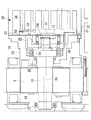
次に、本実施形態の変形例について説明する。
上述した例では、低圧ガス路53は、主軸受部材23を貫通して形成されるとしたが、本発明はこの例に限定されない。例えば、図4に示すように、低圧ガス路54は、クランクピン10Aや回転軸10の軸心を含む部分において、背圧室26から回転軸10の一端側まで貫通して形成される。低圧ガス路54は、一端側が背圧室26に面して形成され、他端側が低圧室14に面して形成される。
この場合も、低圧ガス路53と同様に、低圧ガス路54は、背圧室26と低圧室14を結び、背圧室26内の冷媒ガスを低圧室14へ排出する。本変形例によれば、主軸受部材23に低圧ガス路53を形成する場合よりも加工が容易になる。
Next, a modification of this embodiment will be described.
In the example described above, the low-
Also in this case, similarly to the low
また、上述した例では、高圧の冷媒ガスと中間圧の冷媒ガスをそれぞれ別の管路を経由して背圧室26へ供給するとしたが、本発明はこの例に限定されない。例えば、旋回スクロール33の端板37において、高圧の冷媒ガスと中間圧の冷媒ガスを合流させ、混合したガスを背圧室26へ供給してもよい。
In the above-described example, the high-pressure refrigerant gas and the intermediate-pressure refrigerant gas are supplied to the
例えば、図5及び図6に示すように、混合ガス路55は、旋回スクロール33の端板37に形成され、圧縮機30の内部と背圧室26を結ぶ。
混合ガス路55は、一端側の開口部が旋回スクロール33の端板37の中央付近と、端板37の半径方向中間部分であって、渦巻き状ラップ34が設けられていない部分にそれぞれ形成される。また、混合ガス路55は、他端側の開口部が背圧室26に面して形成される。これにより、混合ガス路55は、圧縮機30の内部と背圧室26を結び、圧縮機30内部で圧縮され高圧及び中間圧まで上昇した冷媒ガスを混合した後、混合されたガスを背圧室26へ供給する。
For example, as shown in FIGS. 5 and 6, the
The
この場合、背圧室26と低圧室14を結ぶ管路は、上述したとおり、主軸受部材23に低圧ガス路53を形成してもよいし(図5参照)、クランクピン10Aや回転軸10の軸心を含む部分に低圧ガス路54を形成してもよい(図6参照)。
In this case, the pipe line connecting the
高圧及び中間圧まで上昇した冷媒ガスを混合した後、混合されたガスを背圧室26へ供給することによって、高圧の冷媒ガスと中間圧の冷媒ガスをそれぞれ別の管路を経由して背圧室26へ供給する場合に比べて、背圧室26内の圧力を均一化しやすくなる。
After mixing the refrigerant gas that has risen to the high pressure and the intermediate pressure, the mixed gas is supplied to the
[第3実施形態]
次に、本発明の第3実施形態について説明する。
スクロール型圧縮機1の構成は、上述した第1実施形態と同様であり、重複する説明を省略する。
第1実施形態では、背圧室26に潤滑油が供給され、潤滑油が有する圧力によって必要背圧力を確保する場合について説明し、第2実施形態では、背圧室26に冷媒ガスが供給され、冷媒ガスが有する圧力によって必要背圧力を確保する場合について説明した。
[Third Embodiment]
Next, a third embodiment of the present invention will be described.
The configuration of the scroll compressor 1 is the same as that of the first embodiment described above, and a duplicate description is omitted.
In the first embodiment, a case will be described in which lubricating oil is supplied to the
本発明は、第1及び第2実施形態の構成に限定されず、両者の構成を組み合わせてもよい。これにより、背圧室26には、潤滑油と冷媒ガスが混合した状態で満たされる。この場合でも、油供給管44、油排出管15、高圧ガス路51、中間圧ガス路52、低圧ガス路53,54、混合ガス路55の組み合わせ方や、管路の断面積及び距離を調整することによって、背圧室26側から旋回スクロール33を固定スクロール32側へ押し付けることができる。また、圧縮機30における圧縮比の高低に応じて、背圧室26内の圧力が過度に高くなることを防止できる。
The present invention is not limited to the configurations of the first and second embodiments, and the configurations of both may be combined. As a result, the
1 スクロール型圧縮機
2 密閉容器
3,4 ハウジング
5 自転阻止機構
5A ピン
5B リング
7 電動モータ
8 ステータ
9 モータロータ
10 回転軸
10A クランクピン
12 ドライブブッシュ
13 バランスウエイト
14 低圧室
15,16 油排出管
22 フロント軸受
23 主軸受部材
24 主軸受
25 シャフトシール
26 背圧室
30 圧縮機
32 固定スクロール
33 旋回スクロール
34 渦巻き状ラップ
36 吐出室
37 端板
38 ドライブ軸受
39 吐出孔
41 オイルセパレータ
42 吐出ポート部
43 油溜め室
44 油供給管
51 高圧ガス路
52 中間圧ガス路
53,54 低圧ガス路
55 混合ガス路
59 イモネジ
DESCRIPTION OF SYMBOLS 1 Scroll type compressor 2 Sealed
Claims (3)
前記圧縮部に面する背圧室と、
オイルセパレータから油が供給される油溜め部と、
前記油溜め部から前記背圧室へ前記油を供給する油供給路と、
前記圧縮部に回転力を伝達する回転軸と、
前記回転軸に形成され、前記背圧室と低圧室を結び、前記油供給路よりも圧力損失が高い油排出路と、
を備え、
前記油排出路は、前記回転軸の外周面に螺旋状に形成された溝を有しているスクロール型圧縮機。 A compression unit having a fixed scroll and a turning scroll that revolves around the fixed scroll; and
A back pressure chamber facing the compression section;
An oil reservoir to which oil is supplied from an oil separator;
An oil supply path for supplying the oil from the oil reservoir to the back pressure chamber;
A rotating shaft for transmitting a rotational force to the compression unit;
An oil discharge passage formed on the rotating shaft, connecting the back pressure chamber and the low pressure chamber, and having a higher pressure loss than the oil supply passage;
Equipped with a,
The oil discharge passage, the scroll-type compressor that has a groove formed in a spiral shape on the outer peripheral surface of the rotary shaft.
前記圧縮部に面する背圧室と、
前記旋回スクロールの端板のうち前記圧縮部内側の高圧領域に形成された開口部と前記背圧室側に形成された開口部とを結ぶ第1ガス流路、及び前記端板のうち前記圧縮部内側の中間圧領域に形成された開口部と前記背圧室側に形成された開口部とを結ぶ第2ガス流路と、
前記背圧室と低圧室を結ぶ第3ガス流路と、
を備え、
前記第1ガス流路、前記第2ガス流路及び前記第3ガス流路は、それぞれ、同じ前記背圧室に直接接続しているスクロール型圧縮機。 A compression unit having a fixed scroll and a turning scroll that revolves around the fixed scroll; and
A back pressure chamber facing the compression section;
A first gas flow path that connects an opening formed in a high-pressure region inside the compression portion of the end plate of the orbiting scroll and an opening formed on the back pressure chamber side, and the compression of the end plate. A second gas flow path connecting an opening formed in the intermediate pressure region inside the section and an opening formed on the back pressure chamber side;
A third gas flow path connecting the back pressure chamber and the low pressure chamber;
With
The scroll type compressor in which the first gas channel, the second gas channel, and the third gas channel are each directly connected to the same back pressure chamber.
前記油溜め部から前記背圧室へ前記油を供給する油供給路と、
前記圧縮部に回転力を伝達する回転軸と、
前記回転軸に形成され、前記背圧室と低圧室を結び、前記油供給路よりも圧力損失が高い油排出路と、
を更に備える請求項2に記載のスクロール型圧縮機。 An oil reservoir to which oil is supplied from an oil separator;
An oil supply path for supplying the oil from the oil reservoir to the back pressure chamber;
A rotating shaft for transmitting a rotational force to the compression unit;
An oil discharge passage formed on the rotating shaft, connecting the back pressure chamber and the low pressure chamber, and having a higher pressure loss than the oil supply passage;
The scroll compressor according to claim 2, further comprising:
Priority Applications (1)
| Application Number | Priority Date | Filing Date | Title |
|---|---|---|---|
| JP2012240486A JP6207828B2 (en) | 2012-10-31 | 2012-10-31 | Scroll compressor |
Applications Claiming Priority (1)
| Application Number | Priority Date | Filing Date | Title |
|---|---|---|---|
| JP2012240486A JP6207828B2 (en) | 2012-10-31 | 2012-10-31 | Scroll compressor |
Publications (2)
| Publication Number | Publication Date |
|---|---|
| JP2014088852A JP2014088852A (en) | 2014-05-15 |
| JP6207828B2 true JP6207828B2 (en) | 2017-10-04 |
Family
ID=50790930
Family Applications (1)
| Application Number | Title | Priority Date | Filing Date |
|---|---|---|---|
| JP2012240486A Expired - Fee Related JP6207828B2 (en) | 2012-10-31 | 2012-10-31 | Scroll compressor |
Country Status (1)
| Country | Link |
|---|---|
| JP (1) | JP6207828B2 (en) |
Families Citing this family (3)
| Publication number | Priority date | Publication date | Assignee | Title |
|---|---|---|---|---|
| WO2016189598A1 (en) * | 2015-05-22 | 2016-12-01 | 三菱電機株式会社 | Scroll compressor |
| CN105464989B (en) * | 2015-12-24 | 2018-03-23 | 珠海格力节能环保制冷技术研究中心有限公司 | A kind of fueller, there is its screw compressor and control method |
| JP6842385B2 (en) | 2017-08-25 | 2021-03-17 | 三菱重工サーマルシステムズ株式会社 | Scroll compressor |
Family Cites Families (5)
| Publication number | Priority date | Publication date | Assignee | Title |
|---|---|---|---|---|
| US5040956A (en) * | 1989-12-18 | 1991-08-20 | Carrier Corporation | Magnetically actuated seal for scroll compressor |
| JP3820824B2 (en) * | 1999-12-06 | 2006-09-13 | ダイキン工業株式会社 | Scroll compressor |
| JP4156494B2 (en) * | 2003-11-06 | 2008-09-24 | 株式会社デンソー | Scroll compressor |
| JP5201113B2 (en) * | 2008-12-03 | 2013-06-05 | 株式会社豊田自動織機 | Scroll compressor |
| JP2012207547A (en) * | 2011-03-29 | 2012-10-25 | Toyota Industries Corp | Electric scroll type compressor |
-
2012
- 2012-10-31 JP JP2012240486A patent/JP6207828B2/en not_active Expired - Fee Related
Also Published As
| Publication number | Publication date |
|---|---|
| JP2014088852A (en) | 2014-05-15 |
Similar Documents
| Publication | Publication Date | Title |
|---|---|---|
| EP3232061B1 (en) | Compressor | |
| US9316225B2 (en) | Scroll compressor with thrust sliding surface oiling groove | |
| JP6628957B2 (en) | Scroll compressor | |
| JP2010043641A (en) | Scroll compressor | |
| JP6715722B2 (en) | Scroll compressor | |
| US8118563B2 (en) | Tandem compressor system and method | |
| JP6207828B2 (en) | Scroll compressor | |
| JP2008240597A (en) | Variable crank mechanism and scroll fluid machine equipped with variable crank mechanism | |
| JP2007138868A (en) | Scroll compressor | |
| US10247188B2 (en) | Scroll compressor | |
| WO2020148857A1 (en) | Scroll compressor | |
| JP5328536B2 (en) | Scroll compressor | |
| JP2003343454A (en) | Slide bush and scroll type fluid machine | |
| JP5863436B2 (en) | Fluid machinery | |
| JP4822943B2 (en) | Fluid machinery | |
| CN105443378B (en) | Scroll compressor and air conditioner | |
| EP3388673A1 (en) | Scroll compressor | |
| JP4604968B2 (en) | Scroll compressor | |
| CN113454341B (en) | Scroll compressor having a discharge port | |
| JP2006241993A (en) | Scroll compressor | |
| KR20210054643A (en) | Compressor | |
| JP4301122B2 (en) | Scroll compressor | |
| JP4301120B2 (en) | Scroll compressor | |
| JP2006009613A (en) | Scroll compressor | |
| JP4935511B2 (en) | Scroll compressor |
Legal Events
| Date | Code | Title | Description |
|---|---|---|---|
| A621 | Written request for application examination |
Free format text: JAPANESE INTERMEDIATE CODE: A621 Effective date: 20150903 |
|
| A977 | Report on retrieval |
Free format text: JAPANESE INTERMEDIATE CODE: A971007 Effective date: 20160519 |
|
| A131 | Notification of reasons for refusal |
Free format text: JAPANESE INTERMEDIATE CODE: A131 Effective date: 20160524 |
|
| A521 | Written amendment |
Free format text: JAPANESE INTERMEDIATE CODE: A523 Effective date: 20160725 |
|
| A131 | Notification of reasons for refusal |
Free format text: JAPANESE INTERMEDIATE CODE: A131 Effective date: 20170110 |
|
| A521 | Written amendment |
Free format text: JAPANESE INTERMEDIATE CODE: A523 Effective date: 20170310 |
|
| TRDD | Decision of grant or rejection written | ||
| A01 | Written decision to grant a patent or to grant a registration (utility model) |
Free format text: JAPANESE INTERMEDIATE CODE: A01 Effective date: 20170808 |
|
| A61 | First payment of annual fees (during grant procedure) |
Free format text: JAPANESE INTERMEDIATE CODE: A61 Effective date: 20170906 |
|
| R150 | Certificate of patent or registration of utility model |
Ref document number: 6207828 Country of ref document: JP Free format text: JAPANESE INTERMEDIATE CODE: R150 |
|
| LAPS | Cancellation because of no payment of annual fees |