EP3299331B1 - Câble de fibre, système de levage avec un tel câble de fibre, et procédé pour faire fonctionner ledit système de levage - Google Patents
Câble de fibre, système de levage avec un tel câble de fibre, et procédé pour faire fonctionner ledit système de levage Download PDFInfo
- Publication number
- EP3299331B1 EP3299331B1 EP16190590.6A EP16190590A EP3299331B1 EP 3299331 B1 EP3299331 B1 EP 3299331B1 EP 16190590 A EP16190590 A EP 16190590A EP 3299331 B1 EP3299331 B1 EP 3299331B1
- Authority
- EP
- European Patent Office
- Prior art keywords
- fibre rope
- hoisting system
- magnets
- rope
- fibre
- Prior art date
- Legal status (The legal status is an assumption and is not a legal conclusion. Google has not performed a legal analysis and makes no representation as to the accuracy of the status listed.)
- Active
Links
Images


Classifications
-
- B—PERFORMING OPERATIONS; TRANSPORTING
- B66—HOISTING; LIFTING; HAULING
- B66C—CRANES; LOAD-ENGAGING ELEMENTS OR DEVICES FOR CRANES, CAPSTANS, WINCHES, OR TACKLES
- B66C1/00—Load-engaging elements or devices attached to lifting or lowering gear of cranes or adapted for connection therewith for transmitting lifting forces to articles or groups of articles
- B66C1/10—Load-engaging elements or devices attached to lifting or lowering gear of cranes or adapted for connection therewith for transmitting lifting forces to articles or groups of articles by mechanical means
- B66C1/12—Slings comprising chains, wires, ropes, or bands; Nets
-
- B—PERFORMING OPERATIONS; TRANSPORTING
- B66—HOISTING; LIFTING; HAULING
- B66C—CRANES; LOAD-ENGAGING ELEMENTS OR DEVICES FOR CRANES, CAPSTANS, WINCHES, OR TACKLES
- B66C13/00—Other constructional features or details
- B66C13/02—Devices for facilitating retrieval of floating objects, e.g. for recovering crafts from water
-
- B—PERFORMING OPERATIONS; TRANSPORTING
- B66—HOISTING; LIFTING; HAULING
- B66C—CRANES; LOAD-ENGAGING ELEMENTS OR DEVICES FOR CRANES, CAPSTANS, WINCHES, OR TACKLES
- B66C15/00—Safety gear
-
- B—PERFORMING OPERATIONS; TRANSPORTING
- B66—HOISTING; LIFTING; HAULING
- B66D—CAPSTANS; WINCHES; TACKLES, e.g. PULLEY BLOCKS; HOISTS
- B66D1/00—Rope, cable, or chain winding mechanisms; Capstans
- B66D1/28—Other constructional details
-
- B—PERFORMING OPERATIONS; TRANSPORTING
- B66—HOISTING; LIFTING; HAULING
- B66D—CAPSTANS; WINCHES; TACKLES, e.g. PULLEY BLOCKS; HOISTS
- B66D1/00—Rope, cable, or chain winding mechanisms; Capstans
- B66D1/28—Other constructional details
- B66D1/40—Control devices
- B66D1/48—Control devices automatic
- B66D1/50—Control devices automatic for maintaining predetermined rope, cable, or chain tension, e.g. in ropes or cables for towing craft, in chains for anchors; Warping or mooring winch-cable tension control
-
- B—PERFORMING OPERATIONS; TRANSPORTING
- B66—HOISTING; LIFTING; HAULING
- B66D—CAPSTANS; WINCHES; TACKLES, e.g. PULLEY BLOCKS; HOISTS
- B66D1/00—Rope, cable, or chain winding mechanisms; Capstans
- B66D1/28—Other constructional details
- B66D1/40—Control devices
- B66D1/48—Control devices automatic
- B66D1/52—Control devices automatic for varying rope or cable tension, e.g. when recovering craft from water
-
- D—TEXTILES; PAPER
- D07—ROPES; CABLES OTHER THAN ELECTRIC
- D07B—ROPES OR CABLES IN GENERAL
- D07B1/00—Constructional features of ropes or cables
- D07B1/14—Ropes or cables with incorporated auxiliary elements, e.g. for marking, extending throughout the length of the rope or cable
- D07B1/145—Ropes or cables with incorporated auxiliary elements, e.g. for marking, extending throughout the length of the rope or cable comprising elements for indicating or detecting the rope or cable status
-
- D—TEXTILES; PAPER
- D07—ROPES; CABLES OTHER THAN ELECTRIC
- D07B—ROPES OR CABLES IN GENERAL
- D07B1/00—Constructional features of ropes or cables
- D07B1/02—Ropes built-up from fibrous or filamentary material, e.g. of vegetable origin, of animal origin, regenerated cellulose, plastics
- D07B1/025—Ropes built-up from fibrous or filamentary material, e.g. of vegetable origin, of animal origin, regenerated cellulose, plastics comprising high modulus, or high tenacity, polymer filaments or fibres, e.g. liquid-crystal polymers
-
- D—TEXTILES; PAPER
- D07—ROPES; CABLES OTHER THAN ELECTRIC
- D07B—ROPES OR CABLES IN GENERAL
- D07B1/00—Constructional features of ropes or cables
- D07B1/14—Ropes or cables with incorporated auxiliary elements, e.g. for marking, extending throughout the length of the rope or cable
- D07B1/148—Ropes or cables with incorporated auxiliary elements, e.g. for marking, extending throughout the length of the rope or cable comprising marks or luminous elements
-
- D—TEXTILES; PAPER
- D07—ROPES; CABLES OTHER THAN ELECTRIC
- D07B—ROPES OR CABLES IN GENERAL
- D07B2205/00—Rope or cable materials
- D07B2205/20—Organic high polymers
- D07B2205/201—Polyolefins
- D07B2205/2014—High performance polyolefins, e.g. Dyneema or Spectra
-
- D—TEXTILES; PAPER
- D07—ROPES; CABLES OTHER THAN ELECTRIC
- D07B—ROPES OR CABLES IN GENERAL
- D07B2205/00—Rope or cable materials
- D07B2205/20—Organic high polymers
- D07B2205/2039—Polyesters
-
- D—TEXTILES; PAPER
- D07—ROPES; CABLES OTHER THAN ELECTRIC
- D07B—ROPES OR CABLES IN GENERAL
- D07B2205/00—Rope or cable materials
- D07B2205/20—Organic high polymers
- D07B2205/2039—Polyesters
- D07B2205/2042—High performance polyesters, e.g. Vectran
-
- D—TEXTILES; PAPER
- D07—ROPES; CABLES OTHER THAN ELECTRIC
- D07B—ROPES OR CABLES IN GENERAL
- D07B2205/00—Rope or cable materials
- D07B2205/30—Inorganic materials
- D07B2205/3007—Carbon
-
- D—TEXTILES; PAPER
- D07—ROPES; CABLES OTHER THAN ELECTRIC
- D07B—ROPES OR CABLES IN GENERAL
- D07B2301/00—Controls
- D07B2301/25—System input signals, e.g. set points
- D07B2301/252—Temperature
-
- D—TEXTILES; PAPER
- D07—ROPES; CABLES OTHER THAN ELECTRIC
- D07B—ROPES OR CABLES IN GENERAL
- D07B2301/00—Controls
- D07B2301/55—Sensors
- D07B2301/5531—Sensors using electric means or elements
- D07B2301/555—Sensors using electric means or elements for measuring magnetic properties
-
- D—TEXTILES; PAPER
- D07—ROPES; CABLES OTHER THAN ELECTRIC
- D07B—ROPES OR CABLES IN GENERAL
- D07B2501/00—Application field
- D07B2501/20—Application field related to ropes or cables
- D07B2501/2015—Construction industries
-
- D—TEXTILES; PAPER
- D07—ROPES; CABLES OTHER THAN ELECTRIC
- D07B—ROPES OR CABLES IN GENERAL
- D07B2501/00—Application field
- D07B2501/20—Application field related to ropes or cables
- D07B2501/2061—Ship moorings
Definitions
- the present invention relates to a fibre rope. More particularly the present invention relates to a fibre rope for offshore hoisting operations wherein the fibre rope comprises magnetic sources embedded therein.
- the invention also relates to a hoisting system for offshore operations as well as to a method for operating such a hoisting system.
- Lifting cranes for deep water operations need winch drums suitable for storing several thousand meters of wire rope, often in the order of 3000 meters or more, thus requiring large, heavy winch drums with equally large footprints.
- For hoisting loads in deep water operations it is often desirable to use fibre ropes due to their reduced weight compared to traditional steel wire ropes.
- a challenge related to the use of fibre ropes is the difficulty of measuring the wear of the fibre ropes, and in particular to predict the lifetime of the fibre ropes.
- the difficulty of the predicting the wear has led to requirements of higher safety factors compared to when working with wire ropes made from steel.
- the industry standard requires a safety factor between 5 and 6 when working with fibre ropes, implying the need for large diameter ropes and correspondingly large and heavy equipment for handling the fibre ropes.
- One of the reasons why it is hard to predict the lifetime of fibre ropes is their very sensitive dependency on temperature, resulting from internal friction between the rope fibres, friction between the rope and the sheaves that it runs over during hoisting operations as well as the ambient temperature.
- the wear might become excessive.
- the fibres may undergo an irreversible recrystallization process already at temperatures in the order of 60°C.
- thermocouples to measure the temperature of wire ropes.
- the thermocouples have been shown to be difficult to install and hold in operation, including to pass over sheaves in the hoisting system.
- thermocouples embedded inside fibre ropes have been shown to influence premature failure of the ropes and thus the need for an even higher safety factor.
- thermocouples repeatedly passing over sheaves in heave compensation mode have been shown to fail prematurely.
- US2008105059A1 discloses a strain gauge sensor system and method for measuring the strain in a fibre rope.
- WO2016037207A2 discloses a fibre rope comprising magnetic marking elements for detecting deformation of the fibre rope.
- WO2015149165A1 discloses a method and apparatus for analysis of synthetic ropes comprising elements for magnetic detection.
- JPH0912271A discloses a device for detecting the rope damage.
- US4718168A discloses a system for cable length measurement correction system.
- the system comprises a cable provided with magnetic marks.
- EP0849208A1 discloses a method and apparatus for inspecting hoisting ropes.
- the cable comprises magnetic permeable material.
- WO2016059652A1 discloses a fibre rope for use in seismic surveillance.
- the invention has for its object to remedy or to reduce at least one of the drawbacks of the prior art, or at least provide a useful alternative to prior art.
- the invention in a first aspect, relates to a hoisting system comprising a fibre rope for offshore lifting operations, wherein said fibre rope comprises a plurality of magnets embedded within the fibre rope with an axial distance therebetween along the fibre rope.
- the distance between the magnets will preferably be predefined.
- the present object is obtained by means of a hoisting system for offshore applications.
- the hoisting system comprising
- the hoisting system is characterized in that the magnets are permanent magnets with a temperature dependent magnetic field strength, and wherein the system further comprises
- the use of axially distributed magnets may be beneficial for measuring the distance between the magnets, where an increased distance indicates elastic or permanent elongation/creep of the rope.
- the magnetic measurements may typically be combined with data about the rope hoisting speed as will be discussed below, though embodiments with a plurality of magnetic sensors provided with a fixed or variable distance therebetween are also envisioned which do not necessarily depend on the rope hoisting speed as input.
- said magnets are permanent magnets with a temperature-dependent magnetic field strength. This may be particularly useful to monitor both information about the rope elongation as well as indirect information about the temperature of the fibre rope through the magnetic field strength. Any magnet with temperature-dependent magnetic field strength may be used, though neodymium-based magnets (also known as NdFeB, NIB or Neo magnets), may be preferable due to their superior magnetic properties and well documented temperature dependence.
- Neodymium magnets which are the most widely used type of rare-earth magnet, are permanent magnets made from an alloy of neodymium, iron and boron to form the Nd 2 Fe 14 B tetragonal crystalline structure.
- Neodymium magnets are usually graded according to their maximum energy product, which relates to the magnetic flux output per unit volume. Higher values indicate stronger magnets and range from N35 up to N52. As embedded within a fibre rope according to the first aspect of the invention, it has been found that magnets of N42 and higher may be preferable due to their field strength, and thus better reliability as source for temperature and length measurements.
- said permanent magnets may be embedded in the core of said fibre rope, which may be useful to get an indirect measure of the core temperature of the fibre rope which would typically not be available from surface measurements.
- it may be beneficial to combine the indirectly measured core temperature with surface temperature measurements of the fibre rope as will be explained below.
- It may be a thermocouple or some other temperature sensor in contact with the fibre rope.
- a non-contact temperature sensor such as an IR sensor, may be used.
- a radial gradient may easily be calculated as an indication of heat dissipation in the radial direction.
- Other locations for the embedded magnets are also envisioned, such as near the surface, or mid-way between the surface and the core.
- a temperature gradient along the fibre rope is already available from the magnetic temperature measurements and/or infrared temperature measurements along the rope.
- said fibre rope may further be provided with a plurality of fibre rope position identification means, such as RFID tags, along the fibre rope.
- a plurality of fibre rope position identification means such as RFID tags
- This may be useful for uniquely identifying different length portions of the wire rope. If combined with magnetic, and potentially other, length measurements, this may be particularly useful for localizing wear such as any excess temperature exposure and potential creep and twist of the fibre rope.
- Other position identification means such as uniquely optically identifiable marks may also be used.
- the fibre rope is provided with a plurality of optically detectable marks provided with an axial distance therebetween along the fibre rope.
- the optical marks may serve as a back-up and/or redundancy for the distributed magnets for length measurements and may as such make the fibre rope more versatile and robust in terms of length measurements. It may be advantageous if positions of the optical marks substantially coincide with the positions of the embedded magnets along the fibre rope, which may simplify measurements and comparisons.
- the distance between the embedded magnets and potentially the optical marks may be in the order of 1 meter, though a variety of different distances may be used.
- the fibre rope may be provided with a continuous and optically detectable mark along at least a portion of said fibre rope.
- This axial and optically detectable mark line may be used as an indicator for rope twist as will be explained below.
- Optically detectable herein implies that it is possible to distinguish it from the rest of the fibre rope by means of an optical sensor, such as by means of a camera, which does not necessarily have to operate in the part of the spectrum that is visible to a human eye.
- the magnetic field strength and direction may also be sensed by said magnetic sensing means.
- a so-called 3D magnetic sensor may be used.
- One example of such a sensor is the three-dimensional hall effect sensor commercially available from Infineon Technologies AG.
- the 3-dimensional mapping may show to be particularly useful if the rope can be measured and codified at defined lengths using different magnetic orientations and numbers.
- the small magnetic temperature variations may thus be detected also by the 3-dimensional magnetic field variation, not only in one axis, but in three axes.
- the magnetic sensing means may in the simplest form be any device capable of sensing the presence of a magnetic field, which may then, together with the speed sensing means, provide a simple, robust and non-contact, non-intrusive distance measurement between the embedded magnets in the fibre rope. This may be useful for indicating creep, permanent elongation or elastic elongation. Still, in a preferred embodiment the magnetic sensing means should also be adapted to sense the magnetic field strength, while at the same time the embedded magnets should have a temperature-dependent magnetic field strength, which may then give an indirect indication of the temperature of the magnets.
- a hall effect sensor may be used for such measurements, and as described above hall effect sensors are also known that may measure the spatial variation of the magnetic field.
- the indirect temperature measurements may typically require a simple calibration in order to uniquely determine the temperature based on magnetic field strength data, however for several known magnetic materials such data may already be available from look-up tables.
- the hoisting system may further be provided with a fibre rope position sensing means for sensing different fibre rope positon identification means for to uniquely identifying different length portions of said fibre rope.
- the fibre rope position sensing means may typically be a RFID reader adapted to uniquely identify passive RFID tags in the fibre rope, but also position sensing means in the form an optical and position identification means in the form of unique optical marks, such as number codes, may be used.
- said hoisting system may further include an optical sensing means for sensing optically detectable marks on said fibre rope.
- the marks may be provided with an axial distance therebetween, as described above, and/or a continuous mark axially along the fibre rope.
- the marks with axial distance between them may be used for measuring elongation, while the axial continuous mark may be used to measure twist of the fibre rope.
- one or more of the cameras may also be used to record the shape of the fibre rope, wherein any ovality and shape change may be detected.
- the optical sensing means may include one or more lasers. The optically detectable marks may, but need not, be visually detectable.
- said magnetic sensing means, said fibre rope position sensing means and said optical sensing means may be provided within a common housing adapted for the passing of the fibre rope therethrough.
- the common housing may simply be provided as a box with holes for the passing of the fibre rope at two opposite ends and with different sensing means, such cameras and sensors distributed axially along and circumferentially around the pathway of the fibre rope inside the housing.
- the housing may be beneficial for protecting the various sensing means, cameras and sensors, but the housing may also be useful for providing a pre-installed tool-kit with known characteristics and positions of the sensing means, including cameras and other sensors. It is therefore claimed that the housing with the various sensing means may even be useful with other types of wire ropes, i.e.
- the housing with different sensing means configurations as described in the following is therefore included as one embodiment of a hoisting system according to the second aspect of the invention as used together with a fibre rope according to the first aspect of the invention.
- the housing with different sensing means configurations as described herein may also be regarded as a separate invention independent of the fibre rope and useful for any kind of wire rope, also outside the offshore environment.
- the hoisting system may further comprise an infrared means for sensing the surface temperature of said fibre rope.
- Said infrared sensing means may also be provided inside said housing if present.
- the infrared sensing means will give an indication of the temperature in the outer radial portion of the fibre rope, and the temperature distribution along length direction of the rope when the rope is moving.
- a temperature gradient in the radial direction of the fibre rope may also be easily calculated, which may be particularly useful for monitoring heat dissipation and the wear of the fibre rope. If the distributed magnets with a temperature-dependent magnetic field strength are embedded at or near the core of the fibre rope, the temperature gradient across the full radius of the fibre rope may be calculated.
- the hoisting system may be a knuckle-boom crane.
- Knuckle-boom cranes are known to be particularly useful in offshore environments, both because they occupy little deck space and because of their low centre of gravity compared to other cranes known to be used offshore.
- the main boom On a knuckle-boom crane, the main boom is hinged at the middle, thus creating a knuckle-boom.
- the luffing motion of both the main boom and the knuckle-boom is usually controlled with hydraulic cylinders. This way, movements of the load can be limited as the boom tip can be kept at a limited height above deck. This feature makes the crane both safe and efficient.
- the winch drum may supported and integrated substantially vertically in a support structure, such as the king, of the knuckle-boom crane as disclosed in PCT/NO2016/050047 , to which reference is made for a more detailed description of this type of knuckle-boom crane.
- the system may be a stand-alone winch system adapted to be used with any kind of crane or hoisting system.
- All sensing means including cameras and other sensors mentioned herein as part of the hoisting system according to the second aspect of the invention may be connected to one or more processing units for processing of recorded data.
- the one or more processing units which typically may include one or more programmable logic controls and/or microcontrollers, may be provided within said common housing if present, or the processing unit may be external to the housing and connected to the cameras and sensors wirelessly or with via various wires.
- the processing unit may also be connected to or provided with a storage unit for storing measured data.
- the hoisting system may be provided with cooling means for cooling at least a portion of the hoisting system and/or for keeping at least a portion of the hoisting system at a controlled atmosphere. Cooling may be constant or it may be triggered when sensed temperature exceeds a predefined limit. In one embodiment the whole winch and winch drum may be provided in a housing with a controlled, cooled atmosphere. Alternatively or in addition, the hoisting system may also be provided with means for cooling sheaves over which the fibre rope runs in heave compensation mode, where the friction-based temperature increase may become particularly emphasized. Cooling may be done by means of water- or electrolyte-based liquids, air jets or other cooling fluids.
- the invention relates to a method for operating a hoisting system according to the second aspect of the invention, the method comprising the steps of:
- the hoisting speed sensing means may be any device adapted to measure and/or calculate the hoisting speed of the wire rope, directly or indirectly.
- the hoisting speed may be calculated from the measured rotational speed of a winch drum from which the fibre rope is reeled or a sheave over which the wire rope runs during a hoisting operation, such as by means of a tachometer or an encoder.
- the encoder may preferably be absolute, though an incremental one may also be useful in most embodiments.
- the conversion from measured magnetic field strength to temperature may be based on pre-calibration of the magnets and/or data found in available look-up tables.
- the reference numeral 1 will indicate a fibre rope according to the first aspect of the present invention
- the reference numeral 10 indicates a hoisting system according to the second aspect of the invention.
- Identical reference numeral will indicate identical or similar features in the drawings.
- the drawings are shown simplified and schematic and the various features in the drawings are not necessarily drawn to scale.
- Fig. 1 shows a part of a fibre rope 1 according to the first aspect of the invention, while the lower portion of the figure shows the same part of the fibre rope 1 in a cross-section along the rope.
- the fibre rope comprises High Modulus Polyethylene (HMPE) and/ or High-Performance Polyethylene (HPPE) fibres, but it could also be based on any other type of fibre, such as e.g. aramid, liquid crystal polymer, polyamides, polyester, carbon etc.
- HMPE High Modulus Polyethylene
- HPPE High-Performance Polyethylene
- the outside of the fibre rope 1 is provided with optically detectable, transverse marks 2 with a fixed, axial distance therebetween.
- the distance in the shown embodiment is in the order of 1 meter and it will be predefined. Other predefined distances may be used in other hoisting systems 10 according to the invention. As will be explained in the following, the distance between consecutive marks 2 will be indirectly measured in real-time, where an increased length may be indicative excessive creep due to heating and/or load.
- the outside out the fibre rope 1 is also provided with an optically detectable continuous mark 4 along the axial length of the shown portion of the fibre rope 1.
- the continuous mark 4 may be used to measure local twisting of the fibre rope 1 as will also be explained below, where excessive twisting may also be a discard criteria.
- the fibre rope 1 is further provided with a plurality of fibre rope position identification means 6, shown as RFID tags in the disclosed embodiment.
- the RFID tags 6 are embedded in the fibre rope 1, such as near the surface of the fibre rope, in order to uniquely identify various length portions of the fibre rope 1.
- the unique identification of various length portions of the fibre rope 1 becomes particularly useful in combination with the sensing of other fibre rope parameters, such as length extension, twist and temperature so as to be able to identify which portions of the fibre rope 1 are exposed to the mentioned wear-critical parameters.
- the distance between the RFID tags 6 along the fibre rope 1 may, but need not be, similar to the distance between the optically detectable transverse marks 2. In the shown embodiment, the optically detectable marks are also visually detectable.
- Fig. 1 shows a cross-section along the length of the fibre rope 1.
- a plurality of magnets 8 are embedded in the fibre rope 1 substantially at the core 12, i.e. the radial centre, of the fibre rope 1.
- the magnets 8 are separated from the rest of the fibre rope 1 by means of a protective sleeve 14, which may be particularly useful if the fibre rope is to be submerged in water.
- the sleeve 14 will create an impediment between the magnets 8 and sea water, thus preventing deterioration and magnetic field loss of the magnets.
- the sleeve 14 may typically comprise a polymeric material which is flexible and compact.
- the magnets 8 are of a permanent type with a temperature-dependent magnetic field strength, which makes it possible to measure the core temperature of the fibre rope by means of magnetic field strength measurements, typically with one or more hall-effect sensors as will be explained below.
- the axial distance between the magnets along the rope may coincide with the distance between the transverse visual marks 2.
- the combined use of both visual transverse marks 2 and embedded magnets 8 gives redundancy in the fibre rope 1 elongation monitoring.
- Fibre ropes 1 are already known that are provided with an internal sleeve 14 for improving radial stiffness of the rope. As such, the magnets 8 may be included inside such a sleeve 14, thus exploiting the already existing infrastructure.
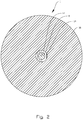
- Fig. 2 is a cross-section, in a larger scale than Fig.1 , of the fibre rope 1 in a plane perpendicular to the length of the fibre rope 1.
- the magnet 8 is shown in the protective sleeve 14 surrounded by HMPE fibre 16.
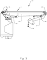
- Fig. 3 shows a hoisting system 10 according to the second aspect of the invention, the hoisting system 10 comprising a fibre rope 1 according to the first aspect of the invention.
- the hoisting system 10 is provided as a knuckle-boom crane 10, though the fibre rope 1 could be used in any kind of hoisting system, including on any kind of crane and also in stand-alone winch systems.
- the knuckle boom crane 10 may be use to lower and lift heavy loads to and from a seabed several thousand meters below sea-level.
- the knuckle-boom crane 10 will be moving together with the vessel on which is it placed due the impact of waves and wind. In certain parts of such a hoisting operation it may be necessary to keep the load substantially fixed relative to the seabed or to another reference system not moving together with the knuckle-boom crane 10. It may therefore be necessary to operate the knuckle-boom crane 10 in heave compensation mode, implying that the same portion of the fibre rope 1 undergoes numerous bending cycles under load, which may lead to excessive heating and potentially unacceptable wear of portions of the fibre rope 1.
- a housing 16 including a plurality of various sensors as will be explained in the following, is installed near a guiding sheave 18 on a main boom 20 of the knuckle-boom crane 10.
- Several such housings 16 may be installed along the length of the wire on the knuckle-boom crane 10 for measuring simultaneously on multiple locations along the fibre rope 1, but only one is used in the shown embodiment.
- Another housing 16 could e.g. be placed near a second guiding sheave 22 at the distal end of the main boom 20 where the knuckle-boom 24 is rotatably connected.
- the luffing motion of the knuckle-boom crane 10 is enabled by means of a first cylinder 19 adapted to lift and lower the main boom 20, while the knuckle-boom crane 10 is further provided with a second cylinder 26 for articulating the knuckle-boom 10 relative to the main boom 20 as will be understood by a person skilled in the art.
- a load suspension member 28 in the form of a hook is connected to the end of the fibre rope 1 hanging from the distal end of the knuckle-boom 24 for the connection of a not shown load to the fibre rope 1.
- the knuckle-boom crane 10 is also adapted to slew in the horizontal plane relative to a not shown pedestal.
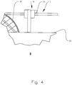
- Fig. 4 shows an enlarged portion of the encircled part B from Fig. 3 .
- the figure shows schematically the fibre rope 1 running through the housing 16 covering multiple sensors.
- the housing 16 is placed immediately after the guiding sheave 18 on the main boom 20 in the direction from the not shown winch drum towards the second guiding sheave 22 and the load suspension member 24 as shown in Fig. 3 .
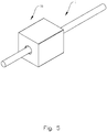
- the housing 16 with the fibre rope 1 running therethrough is shown in a perspective view in Fig. 5 and in a semi-transparent perspective view in Fig. 7 , while Fig. 6 shows the housing 16 and fibre rope 1 in an end-view in an upper portion of the figure and in a cross-section through the line A-A in the lower portion of the figure.
- the magnetic sensors 30 are adapted to sense the passing of the magnets 8 through the housing 16.
- the hoisting system 10 is also provided with a not shown control unit including a timer function for measuring the time between the passing of consecutive magnets. Combined with input about fibre rope 1 speed, this makes it possible to calculate the distance between the embedded magnets 8, and hence also any change in distance.
- the magnets 8 are of a permanent type with a magnetic field strength dependent on temperature.
- the magnetic sensors 30 are therefore, in this shown embodiment, of a type adapted to measure the magnetic field strength of the magnets 8. This makes it possible to calculate the core temperature of the fibre rope 1 in a reliable, efficient and non-intrusive way. The conversion from magnetic field strength to temperature may be found in a simple pre-calibration experiment, or it may also be found in look-up tables for certain frequently used permanent magnets as mentioned herein.
- the magnetic sensors 30 are adapted to sense the direction of the magnetic field.
- the sensors used in this specific embodiment are three-dimensional magnetic hall effect sensors commercially available from the company Infineon Technologies AG.
- the housing is also provided with a fibre rope position sensing means 32, here in the form of a RFID sensor/reader for uniquely identifying the RFID tags 6 embedded in the fibre rope 1. Giving each length portion of the fibre rope 1 its own unique recognizable signature is very useful for knowing which portions of the fibre rope 1 that are subject to wear, creep, twist etc. at any time.
- the not shown control unit is connected to or comprises a storage unit adapted to store measured and calculated data from the different portions of the fibre rope 1, such as temperature data, elongation data, twist data, number of bending cycles under load data etc. Data from different time intervals may be compared so as to detect change.
- the housing 16 is further provided with cameras 34 for monitoring the transverse and continuous visual marks 2, 4.
- a plurality of such cameras may be distributed circumferentially around the fibre rope in the housing 16. In the shown embodiment only two cameras are used, but in alternative embodiments more cameras 34 may be used. In a particularly useful embodiment four cameras 34 may be placed evenly around the fibre rope 1 with 90° between each.
- the cameras 34 may be used in the same way as the magnets 8 to measure the distance between the transverse marks 2 so as to monitor any elongation of the fibre rope 1.
- the cameras 34 also monitor the axial continuous mark 4. The time from when one and the same camera 34 sees the continuous mark 4 to the next time the same camera 34 sees the continuous mark 4, i.e. the time between each 360° twist of the fibre rope, can be used to calculate the twist per meter.
- a control unit timer starts. The timer stops when the same camera 34 sees the continuous mark again.
- the cameras 34 will also monitor the shape and ovality of the fibre rope 1, while the control unit compares the latest data with the original shape and ovality of the fibre rope 1.
- the shape change such a reduction in diameter, may also be compared with the elongation of the fibre rope 1.
- An increase in diameter compared to a set value will typically be an indication of slack in the fibre rope 1 or degraded fibres which may also be cross-checked by a not shown load cell value.
- the shape of the fibre rope 1 is determined by different images captured by cameras 34 circumferentially arranged with a defined angle therebetween, and/or with the inclusion of a not shown laser beams.
- the shape change is observed by image analysis in a control unit as will be mentioned below.
- the knuckle-boom crane 10 is further provided with an infrared (IR) sensor 36 for measuring the surface temperature of the fibre rope 1.
- IR infrared
- the IR sensor 36 is provided outside the housing 16, however the IR sensor could equally well be included inside the housing 16.
- the hall effect sensors 30 indirectly measure the core temperature of the fibre rope 1
- the IR sensor 36 mainly measure the surface temperature of the fibre rope 1.
- the speed of the fibre rope 1 is used as input for length measurements in combination with a timer.
- the rope speed is, in this embodiment, input from a not shown tachometer.
- the length measurements are used as input both for monitoring elongation and twist, but also in combination with the temperature measurements and monitoring of bending cycles under load to give an overall overview of wear and creep of the fibre rope 1.
- the RFIDs tags 6 and readers 32 are continuously used to identify different length portions of the fibre rope 1. Both excessive creep and twist are used as discard criteria for the worn portion of the fibre rope 1.
- the worn portion of the fibre rope 1 may be cut away and the two remaining ends may be spliced as will be known by a person skilled in the art.
- Examples of discard criteria may be 10% creep and/or 1 full twist per 10 meters, but these parameters will depend greatly on and vary between different types of fibre ropes 1. Excessive heating may also be a separate discard criterion due to the irreversible recrystallization mentioned introductorily. It should be noted that the mentioned limits may vary greatly between different hoisting systems 10 and in particular between different types of fibre ropes 1.
- the hoisting system 10 includes one or more not shown cooling members. Some portions of the hoisting system 10, such as the winch drum, may be stored in a housing with a constantly controlled and cooled atmosphere. Other parts of the hoisting system 10, such as the area around the guiding sheaves 18, 22 where the fibre rope 1 undergoes numerous bending cycles and the temperature increases due to internal and external friction in the fibre rope 1, may be cooled when the fibre rope reaches a pre-set temperature. The conditional cooling will typically take place when the hoisting system 10 is set in heave compensation mode, where it may operate for several hours. Cooling may be done by means of flushing with water, electrolytes, air jets or other cooling fluids.
Landscapes
- Engineering & Computer Science (AREA)
- Mechanical Engineering (AREA)
- Chemical & Material Sciences (AREA)
- Crystallography & Structural Chemistry (AREA)
- Ropes Or Cables (AREA)
- Load-Engaging Elements For Cranes (AREA)
Claims (15)
- Un système de levage (10) pour des opérations de levage en mer, ledit système de levage (10) comprenant
un câble de fibre (1) comprenant une pluralité d'aimants (8) incorporés à l'intérieur du câble de fibre (1) avec une distance axiale entre eux, le long du câble de fibre (1),- un moyen de détection magnétique (30) configuré pour détecter la présence et l'intensité du champ magnétique des dits aimants (8) intégrés dans le câble de fibre (1),
caractérisé en ce que
les dits aimants (8) sont des aimants permanents avec une intensité de champ magnétique dépendante de la température, et dans lequel de système (10) comprend en outre- une unité de commande pour calculer la température des aimants (8) sur la base de la dite intensité de champ magnétique mesurée. - Le système de levage (10) selon la revendication 1, dans lequel les dits aimants permanents sont intégrés dans l'âme (12) du dit câble de fibre (1).
- Le système de levage (10) selon la revendication 1 ou 2, dans lequel le dit câble de fibre est en outre pourvu d'une pluralité de moyens d'identification de position de corde de fibre (6), tels que des étiquettes RFID, le long de la corde en fibre.
- Le système de levage (10) selon l'une quelconque des revendications précédentes, dans lequel le câble de fibre (1) est pourvu d'une pluralité de repères optiquement détectables (2) prévus avec une distance axiale entre eux le long du câble de fibre (1).
- Le système de levage (10) selon la revendication 4, dans lequel les positions axiales desdits repères optiquement détectables (2) coïncident sensiblement avec les positions axiales des dits aimants (8) le long du câble de fibre (1).
- Le système de levage (10) selon l'une quelconque des revendications précédentes, dans lequel le dit câble de fibre (1) est pourvu d'un repère continu et optiquement détectable (4) le long d'au moins une partie du dit câble de fibre (1).
- Le système de levage (10) selon l'une quelconque des revendications précédentes, dans lequel le moyen de détection magnétique (30) est configuré pour détecter l'orientation du champ magnétique.
- Le système de levage (10) selon l'une quelconque des revendications précédentes, dans lequel le système de levage (10) est en outre pourvu d'un moyen de détection de position (32) du câble de fibre (1) pour détecter des différents moyens d'identification de position (6) du câble en fibre (1) de manière à identifier de manière unique des différentes parties dudit câble de fibre (1).
- Le système de levage (10) selon l'une quelconque des revendications précédentes, dans lequel ledit système de levage (10) comprend en outre un moyen de détection optique (34) pour détecter des repères détectables optiquement (2, 4) sur ledit câble de fibre (1).
- Le système de levage selon l'une quelconque des revendications précédentes, dans lequel lesdits moyens de détection magnétique (30), lesdits moyens de détection de position de câble de fibre (32) et lesdits moyens de détection optique (34) sont intégrés dans un boîtier commun (16) adapté pour le passage du câble de fibre (1) à travers.
- Le système de levage (10) selon l'une quelconque des revendications précédentes, dans lequel le système de levage (10) comprend en outre un moyen de détection infrarouge (36) pour détecter la température dudit câble de fibre (1), et de préférence la température de surface externe dudit câble de fibre (1).
- Le système de levage (10) selon l'une quelconque des revendications précédentes, dans lequel le système de levage est une grue à flèche articulée ou un système de treuil autonome.
- Le système de levage (10) selon l'une quelconque des revendications précédentes, dans lequel le système de levage comprend des moyens de détection de vitesse de levage de câble de fibres.
- Un procédé pour faire fonctionner un système de levage (10) selon l'une quelconque des revendications 1 à 13, le procédé comprenant les étapes de:- mesurer l'intensité du champ magnétique des dits aimants (8) intégrés dans le câble de fibres; et- mesurer la température des aimants (8) au moyen de l'intensité du champ magnétique mesurée.
- Le procédé pour faire fonctionner un système de levage (10) selon la revendications 14 le procédé comprenant les étapes de:- mesurer la vitesse de levage dudit câble de fibres (1) au moyen desdits moyens de détection de vitesse de levage de câble de fibres;- mesurer le temps entre le passage d'aimants consécutifs (8) au moyen des dits moyens de détection magnétique (30);- calculer la distance entre des aimants consécutifs (8) au moyen de ladite vitesse de levage mesurée et dudit temps mesuré entre le passage desdits aimants consécutifs; et- comparer la dite distance calculée entre les aimants (8) avec une distance originale prédéfinie entre les aimants.
Priority Applications (6)
| Application Number | Priority Date | Filing Date | Title |
|---|---|---|---|
| EP16190590.6A EP3299331B1 (fr) | 2016-09-26 | 2016-09-26 | Câble de fibre, système de levage avec un tel câble de fibre, et procédé pour faire fonctionner ledit système de levage |
| BR112019005710-2A BR112019005710B1 (pt) | 2016-09-26 | 2017-09-26 | Sistema de içamento para aplicações marítimas e método para operar um sistema de içamento |
| AU2017330162A AU2017330162B2 (en) | 2016-09-26 | 2017-09-26 | Fibre rope and hoisting system including such a fibre rope |
| PCT/NO2017/050246 WO2018056838A1 (fr) | 2016-09-26 | 2017-09-26 | Câble de fibre et système de hissage le comprenant |
| CN201780059211.4A CN109790680B (zh) | 2016-09-26 | 2017-09-26 | 纤维绳及包括这种纤维绳的吊升系统 |
| US16/335,181 US11572656B2 (en) | 2016-09-26 | 2017-09-26 | Fibre rope and hoisting system including such a fibre rope |
Applications Claiming Priority (1)
| Application Number | Priority Date | Filing Date | Title |
|---|---|---|---|
| EP16190590.6A EP3299331B1 (fr) | 2016-09-26 | 2016-09-26 | Câble de fibre, système de levage avec un tel câble de fibre, et procédé pour faire fonctionner ledit système de levage |
Publications (2)
| Publication Number | Publication Date |
|---|---|
| EP3299331A1 EP3299331A1 (fr) | 2018-03-28 |
| EP3299331B1 true EP3299331B1 (fr) | 2020-03-18 |
Family
ID=56997394
Family Applications (1)
| Application Number | Title | Priority Date | Filing Date |
|---|---|---|---|
| EP16190590.6A Active EP3299331B1 (fr) | 2016-09-26 | 2016-09-26 | Câble de fibre, système de levage avec un tel câble de fibre, et procédé pour faire fonctionner ledit système de levage |
Country Status (6)
| Country | Link |
|---|---|
| US (1) | US11572656B2 (fr) |
| EP (1) | EP3299331B1 (fr) |
| CN (1) | CN109790680B (fr) |
| AU (1) | AU2017330162B2 (fr) |
| BR (1) | BR112019005710B1 (fr) |
| WO (1) | WO2018056838A1 (fr) |
Families Citing this family (14)
| Publication number | Priority date | Publication date | Assignee | Title |
|---|---|---|---|---|
| PT3430195T (pt) * | 2016-03-13 | 2024-02-14 | Hampiðjan Hf | Corda de fibra indicadora de calor |
| DE102019207378A1 (de) * | 2018-09-05 | 2020-03-05 | Bosch Rexroth Ag | Seil, winde und windensystem |
| FR3086393B1 (fr) * | 2018-09-20 | 2024-01-19 | Commissariat Energie Atomique | Procede de verification d'une corde |
| DE102019004240B4 (de) * | 2019-06-18 | 2024-04-25 | Mike Pfennig | Gerät zur Prüfung von Stahldrahtseilen und Verfahren zu dessen Anwendung |
| US11473916B1 (en) * | 2019-08-26 | 2022-10-18 | Rhub Communications, Inc. | Rope-based indoor infrastructure free localization |
| DE102020000364A1 (de) | 2020-01-22 | 2021-07-22 | Hermedia Verlag Gmbh | Flexibles Seil mit integrierten magnetischen oder magnetisierbaren Metallelementen |
| CN111485257A (zh) * | 2020-05-21 | 2020-08-04 | 贵州创新轻金属工艺装备工程技术研究中心有限公司 | 一种基于正交脉冲技术的电解槽母线保护的拉绳装置 |
| DE102020133217A1 (de) | 2020-10-30 | 2022-05-05 | Liebherr-Components Biberach Gmbh | Seilwinde |
| CN113148887A (zh) * | 2021-04-20 | 2021-07-23 | 大连海事大学 | 一种用于科考船绞车系统缆绳温度检测装置及其使用方法 |
| CN113184739A (zh) * | 2021-05-07 | 2021-07-30 | 大连海事大学 | 一种深水重载绞车系统及其使用方法 |
| CN114772467B (zh) * | 2022-04-22 | 2024-11-22 | 江苏省建筑工程集团有限公司 | 基于图像识别的塔机顶升过程中垂直度监测系统及方法 |
| JP7731932B2 (ja) * | 2023-03-16 | 2025-09-01 | 株式会社三井E&S | ワイヤロープの診断方法および診断システム並びに診断プログラム |
| CN118619104B (zh) * | 2024-08-13 | 2024-11-01 | 山东兴源机械有限公司 | 一种起重机吊索具用支撑装置 |
| CN120469506A (zh) * | 2025-05-09 | 2025-08-12 | 大连海事大学 | 深海起重机纤维绳温控方法及系统 |
Family Cites Families (35)
| Publication number | Priority date | Publication date | Assignee | Title |
|---|---|---|---|---|
| GB1487978A (en) * | 1974-09-12 | 1977-10-05 | Bando Chemical Ind | Safety device for conveyor belt |
| CA1171933A (fr) * | 1980-06-23 | 1984-07-31 | Yasushi Wakahara | Appareil servant a la detection des variations de temperature ponctuelles d'un objet et du site desdites variations |
| US4438402A (en) * | 1981-06-26 | 1984-03-20 | Autech Corporation | Electrostatic transducer for length measurement system |
| US4718168A (en) * | 1985-12-19 | 1988-01-12 | Kerr Measurement Systems, Inc. | Cable length measurement correction system |
| JPH0912271A (ja) * | 1995-06-30 | 1997-01-14 | Sumitomo Constr Mach Co Ltd | クレーンのロープ損傷検出装置 |
| DE19643997C2 (de) * | 1996-10-31 | 2002-12-05 | Contitech Transportbandsysteme | Verfahren zur Überwachung eines Fördergurtes |
| US5992574A (en) * | 1996-12-20 | 1999-11-30 | Otis Elevator Company | Method and apparatus to inspect hoisting ropes |
| IL133050A (en) * | 1998-12-07 | 2003-12-10 | Inventio Ag | Device for identification of need to replace synthetic fiber ropes |
| IL133736A (en) * | 1999-01-22 | 2003-10-31 | Inventio Ag | Synthetic fibre cable |
| JP4009390B2 (ja) * | 1999-05-27 | 2007-11-14 | 清水建設株式会社 | ブラッグ格子型振動計 |
| US6879759B2 (en) * | 2001-01-08 | 2005-04-12 | Alcatel | Apparatus and method for on-line binder laylength measurement and adjustment |
| US7117981B2 (en) * | 2001-12-19 | 2006-10-10 | Otis Elevator Company | Load bearing member for use in an elevator system having external markings for indicating a condition of the assembly |
| WO2005005292A1 (fr) | 2003-07-09 | 2005-01-20 | Bridgestone Corporation | Procede et dispositif pour mesurer l'elongation, l'usure et la temperature d'une bande transporteuse, feuille de caoutchoic magnetique, et procede de fabrication de cette feuille |
| JP2006156423A (ja) * | 2003-07-09 | 2006-06-15 | Bridgestone Corp | ゴム磁石シートおよびゴム磁石シートの製造方法 |
| JP2005139001A (ja) * | 2003-11-04 | 2005-06-02 | Inventio Ag | 支持手段を点検する方法および装置 |
| WO2005082763A1 (fr) * | 2004-03-01 | 2005-09-09 | Mitsubishi Denki Kabushiki Kaisha | Cable en resine et capteur de position d’ascenseur l’utilisant |
| JP4932222B2 (ja) * | 2005-04-13 | 2012-05-16 | 株式会社ブリヂストン | コンベヤベルトの摩耗検出装置 |
| US7441464B2 (en) * | 2006-11-08 | 2008-10-28 | Honeywell International Inc. | Strain gauge sensor system and method |
| AT10056U1 (de) * | 2007-03-30 | 2008-08-15 | Teufelberger Gmbh | Textiles erzeugnis |
| JP2009003048A (ja) * | 2007-06-20 | 2009-01-08 | Kyocera Mita Corp | 定着装置及び画像形成装置 |
| JP5258306B2 (ja) * | 2008-01-16 | 2013-08-07 | 株式会社ブリヂストン | ベルトモニタリングシステム |
| CA2760939C (fr) * | 2009-05-05 | 2019-08-20 | Actuant Corporation | Evaluation sans contact de la propriete de propagation d'un signal acoustique d'une corde en fibre synthetique |
| DE202011001846U1 (de) * | 2011-01-24 | 2012-04-30 | Liebherr-Components Biberach Gmbh | Vorrichtung zur Erkennung der Ablegereife eines hochfesten Faserseils beim Einsatz an Hebezeugen |
| CN104517667A (zh) * | 2013-10-08 | 2015-04-15 | 国家电网公司 | 一种能实时测温的铝基碳纤维复合材料芯导线 |
| GB201318254D0 (en) * | 2013-10-15 | 2013-11-27 | Silixa Ltd | Optical fiber cable |
| US9791301B2 (en) * | 2014-01-10 | 2017-10-17 | Ndt Technologies, Inc. | Method and apparatus for wire rope distance measurement |
| EP3119716B1 (fr) * | 2014-03-21 | 2018-10-10 | Liebherr-Components Biberach GmbH | Dispositif servant à déterminer le moment de dépose d'un câble lorsqu'il est utilisé sur des engins de levage |
| KR101973067B1 (ko) * | 2014-04-02 | 2019-08-16 | 허 마제스티 더 퀸 인 라이트 오브 캐나다 에즈 리프레젠티드 바이 더 미니스터 오브 내츄럴 리소시스 캐나다 | 합성 로프 또는 케이블의 분석 장치 및 그 용도의 방법 |
| AT14635U1 (de) * | 2014-09-11 | 2016-02-15 | Teufelberger Holding Ag | Faserseil |
| WO2016059652A1 (fr) * | 2014-10-17 | 2016-04-21 | Hampidjan Hf. | Dispositif super large d'alerte au fluage |
| CN204461338U (zh) * | 2015-03-11 | 2015-07-08 | 武汉静磁栅机电制造有限公司 | 基于磁感应传感器的高精度直线位移检测装置 |
| EP3072844B1 (fr) * | 2015-03-27 | 2018-08-01 | National Oilwell Varco Norway AS | Grue de levage en mer |
| CN105513706A (zh) * | 2015-08-23 | 2016-04-20 | 国网山东省电力公司临沂供电公司 | 一种输电线路用纤维复合芯导线 |
| US10660266B2 (en) * | 2016-05-03 | 2020-05-26 | Contitech Transportbandsysteme Gmbh | System and method for monitoring an agricultural belt |
| WO2018109824A1 (fr) * | 2016-12-13 | 2018-06-21 | 東京製綱株式会社 | Procédé de détection de dommages d'un câble métallique, et dispositif de traitement de signaux et dispositif de détection de dommages servant à la détection de dommages d'un câble métallique |
-
2016
- 2016-09-26 EP EP16190590.6A patent/EP3299331B1/fr active Active
-
2017
- 2017-09-26 WO PCT/NO2017/050246 patent/WO2018056838A1/fr not_active Ceased
- 2017-09-26 AU AU2017330162A patent/AU2017330162B2/en active Active
- 2017-09-26 US US16/335,181 patent/US11572656B2/en active Active
- 2017-09-26 BR BR112019005710-2A patent/BR112019005710B1/pt active IP Right Grant
- 2017-09-26 CN CN201780059211.4A patent/CN109790680B/zh active Active
Non-Patent Citations (1)
| Title |
|---|
| None * |
Also Published As
| Publication number | Publication date |
|---|---|
| US20210277598A1 (en) | 2021-09-09 |
| WO2018056838A1 (fr) | 2018-03-29 |
| CN109790680A (zh) | 2019-05-21 |
| CN109790680B (zh) | 2021-08-31 |
| AU2017330162B2 (en) | 2019-12-19 |
| BR112019005710B1 (pt) | 2022-11-29 |
| AU2017330162A1 (en) | 2019-04-04 |
| EP3299331A1 (fr) | 2018-03-28 |
| US11572656B2 (en) | 2023-02-07 |
| BR112019005710A2 (pt) | 2019-07-09 |
Similar Documents
| Publication | Publication Date | Title |
|---|---|---|
| EP3299331B1 (fr) | Câble de fibre, système de levage avec un tel câble de fibre, et procédé pour faire fonctionner ledit système de levage | |
| US10421647B2 (en) | Device for monitoring operating data and/or determining the replacement state of wear of a cable during use on lifting apparatuses | |
| ES2554466T3 (es) | Dispositivo para reconocer el estado de recambio de un cable de fibras altamente resistente durante su utilización en equipos de izado | |
| EP3589785B1 (fr) | Terminaison intelligente de corde ou de câble | |
| CN100387504C (zh) | 具有外部标记的升运带 | |
| AU650359B2 (en) | Load moment indicator system | |
| CN106470930B (zh) | 绳索实时监测 | |
| US11162856B2 (en) | Intelligent fiber rope termination, module, and networking technologies | |
| CN100526195C (zh) | 绳索式或链式滑车组和用于确定其提升重量的方法 | |
| EP3418234B1 (fr) | Ensemble de terminaison d'ascenseur qui fournit une indication de charge de cabine d'ascenseur | |
| US20150198463A1 (en) | Method and apparatus for wire rope distance measurement | |
| US7267241B2 (en) | Device for determining a load on a hoist | |
| WO2015110791A1 (fr) | Système de surveillance | |
| CN220393017U (zh) | 一种煤矿矿井用的钢丝绳检测装置 | |
| KR20140042289A (ko) | 배관용 행거의 지침 표시장치 및 방법 | |
| JP2013252946A (ja) | 作業機械 | |
| KR102903749B1 (ko) | 지능형 섬유 로프 종단, 모듈, 및 네트워킹 기술들 | |
| RU2489542C1 (ru) | Канат и способ его дефектоскопии | |
| RU2346879C2 (ru) | Устройство для измерения угла наклона каната грузоподъемной машины (варианты) | |
| Bossolini et al. | Thermal properties of Fiber ropes | |
| NO20131666A1 (no) | Fremgangsmåte og system for å detektere forekommende slakk heiseline i en vinsj | |
| CA2197583A1 (fr) | Systeme d'indicateur de capacite et de mesure de charge pour appareils de levage |
Legal Events
| Date | Code | Title | Description |
|---|---|---|---|
| PUAI | Public reference made under article 153(3) epc to a published international application that has entered the european phase |
Free format text: ORIGINAL CODE: 0009012 |
|
| STAA | Information on the status of an ep patent application or granted ep patent |
Free format text: STATUS: THE APPLICATION HAS BEEN PUBLISHED |
|
| AK | Designated contracting states |
Kind code of ref document: A1 Designated state(s): AL AT BE BG CH CY CZ DE DK EE ES FI FR GB GR HR HU IE IS IT LI LT LU LV MC MK MT NL NO PL PT RO RS SE SI SK SM TR |
|
| AX | Request for extension of the european patent |
Extension state: BA ME |
|
| STAA | Information on the status of an ep patent application or granted ep patent |
Free format text: STATUS: REQUEST FOR EXAMINATION WAS MADE |
|
| 17P | Request for examination filed |
Effective date: 20180928 |
|
| RBV | Designated contracting states (corrected) |
Designated state(s): AL AT BE BG CH CY CZ DE DK EE ES FI FR GB GR HR HU IE IS IT LI LT LU LV MC MK MT NL NO PL PT RO RS SE SI SK SM TR |
|
| STAA | Information on the status of an ep patent application or granted ep patent |
Free format text: STATUS: EXAMINATION IS IN PROGRESS |
|
| 17Q | First examination report despatched |
Effective date: 20190320 |
|
| RIC1 | Information provided on ipc code assigned before grant |
Ipc: B66D 1/50 20060101ALI20190906BHEP Ipc: D07B 1/14 20060101ALI20190906BHEP Ipc: B66D 1/52 20060101ALI20190906BHEP Ipc: B66B 7/12 20060101ALI20190906BHEP Ipc: D07B 1/02 20060101ALI20190906BHEP Ipc: B66C 1/12 20060101AFI20190906BHEP Ipc: B66C 13/02 20060101ALI20190906BHEP Ipc: B66C 15/00 20060101ALI20190906BHEP |
|
| GRAP | Despatch of communication of intention to grant a patent |
Free format text: ORIGINAL CODE: EPIDOSNIGR1 |
|
| STAA | Information on the status of an ep patent application or granted ep patent |
Free format text: STATUS: GRANT OF PATENT IS INTENDED |
|
| INTG | Intention to grant announced |
Effective date: 20191023 |
|
| GRAS | Grant fee paid |
Free format text: ORIGINAL CODE: EPIDOSNIGR3 |
|
| GRAA | (expected) grant |
Free format text: ORIGINAL CODE: 0009210 |
|
| STAA | Information on the status of an ep patent application or granted ep patent |
Free format text: STATUS: THE PATENT HAS BEEN GRANTED |
|
| AK | Designated contracting states |
Kind code of ref document: B1 Designated state(s): AL AT BE BG CH CY CZ DE DK EE ES FI FR GB GR HR HU IE IS IT LI LT LU LV MC MK MT NL NO PL PT RO RS SE SI SK SM TR |
|
| REG | Reference to a national code |
Ref country code: GB Ref legal event code: FG4D |
|
| REG | Reference to a national code |
Ref country code: DE Ref legal event code: R096 Ref document number: 602016031894 Country of ref document: DE |
|
| REG | Reference to a national code |
Ref country code: AT Ref legal event code: REF Ref document number: 1245702 Country of ref document: AT Kind code of ref document: T Effective date: 20200415 Ref country code: IE Ref legal event code: FG4D |
|
| REG | Reference to a national code |
Ref country code: NL Ref legal event code: FP |
|
| REG | Reference to a national code |
Ref country code: NO Ref legal event code: T2 Effective date: 20200318 |
|
| PG25 | Lapsed in a contracting state [announced via postgrant information from national office to epo] |
Ref country code: RS Free format text: LAPSE BECAUSE OF FAILURE TO SUBMIT A TRANSLATION OF THE DESCRIPTION OR TO PAY THE FEE WITHIN THE PRESCRIBED TIME-LIMIT Effective date: 20200318 Ref country code: FI Free format text: LAPSE BECAUSE OF FAILURE TO SUBMIT A TRANSLATION OF THE DESCRIPTION OR TO PAY THE FEE WITHIN THE PRESCRIBED TIME-LIMIT Effective date: 20200318 |
|
| PG25 | Lapsed in a contracting state [announced via postgrant information from national office to epo] |
Ref country code: BG Free format text: LAPSE BECAUSE OF FAILURE TO SUBMIT A TRANSLATION OF THE DESCRIPTION OR TO PAY THE FEE WITHIN THE PRESCRIBED TIME-LIMIT Effective date: 20200618 Ref country code: LV Free format text: LAPSE BECAUSE OF FAILURE TO SUBMIT A TRANSLATION OF THE DESCRIPTION OR TO PAY THE FEE WITHIN THE PRESCRIBED TIME-LIMIT Effective date: 20200318 Ref country code: SE Free format text: LAPSE BECAUSE OF FAILURE TO SUBMIT A TRANSLATION OF THE DESCRIPTION OR TO PAY THE FEE WITHIN THE PRESCRIBED TIME-LIMIT Effective date: 20200318 Ref country code: HR Free format text: LAPSE BECAUSE OF FAILURE TO SUBMIT A TRANSLATION OF THE DESCRIPTION OR TO PAY THE FEE WITHIN THE PRESCRIBED TIME-LIMIT Effective date: 20200318 Ref country code: GR Free format text: LAPSE BECAUSE OF FAILURE TO SUBMIT A TRANSLATION OF THE DESCRIPTION OR TO PAY THE FEE WITHIN THE PRESCRIBED TIME-LIMIT Effective date: 20200619 |
|
| REG | Reference to a national code |
Ref country code: LT Ref legal event code: MG4D |
|
| PG25 | Lapsed in a contracting state [announced via postgrant information from national office to epo] |
Ref country code: EE Free format text: LAPSE BECAUSE OF FAILURE TO SUBMIT A TRANSLATION OF THE DESCRIPTION OR TO PAY THE FEE WITHIN THE PRESCRIBED TIME-LIMIT Effective date: 20200318 Ref country code: SM Free format text: LAPSE BECAUSE OF FAILURE TO SUBMIT A TRANSLATION OF THE DESCRIPTION OR TO PAY THE FEE WITHIN THE PRESCRIBED TIME-LIMIT Effective date: 20200318 Ref country code: PT Free format text: LAPSE BECAUSE OF FAILURE TO SUBMIT A TRANSLATION OF THE DESCRIPTION OR TO PAY THE FEE WITHIN THE PRESCRIBED TIME-LIMIT Effective date: 20200812 Ref country code: SK Free format text: LAPSE BECAUSE OF FAILURE TO SUBMIT A TRANSLATION OF THE DESCRIPTION OR TO PAY THE FEE WITHIN THE PRESCRIBED TIME-LIMIT Effective date: 20200318 Ref country code: IS Free format text: LAPSE BECAUSE OF FAILURE TO SUBMIT A TRANSLATION OF THE DESCRIPTION OR TO PAY THE FEE WITHIN THE PRESCRIBED TIME-LIMIT Effective date: 20200718 Ref country code: RO Free format text: LAPSE BECAUSE OF FAILURE TO SUBMIT A TRANSLATION OF THE DESCRIPTION OR TO PAY THE FEE WITHIN THE PRESCRIBED TIME-LIMIT Effective date: 20200318 Ref country code: CZ Free format text: LAPSE BECAUSE OF FAILURE TO SUBMIT A TRANSLATION OF THE DESCRIPTION OR TO PAY THE FEE WITHIN THE PRESCRIBED TIME-LIMIT Effective date: 20200318 Ref country code: LT Free format text: LAPSE BECAUSE OF FAILURE TO SUBMIT A TRANSLATION OF THE DESCRIPTION OR TO PAY THE FEE WITHIN THE PRESCRIBED TIME-LIMIT Effective date: 20200318 |
|
| REG | Reference to a national code |
Ref country code: AT Ref legal event code: MK05 Ref document number: 1245702 Country of ref document: AT Kind code of ref document: T Effective date: 20200318 |
|
| REG | Reference to a national code |
Ref country code: DE Ref legal event code: R097 Ref document number: 602016031894 Country of ref document: DE |
|
| PLBE | No opposition filed within time limit |
Free format text: ORIGINAL CODE: 0009261 |
|
| STAA | Information on the status of an ep patent application or granted ep patent |
Free format text: STATUS: NO OPPOSITION FILED WITHIN TIME LIMIT |
|
| PG25 | Lapsed in a contracting state [announced via postgrant information from national office to epo] |
Ref country code: IT Free format text: LAPSE BECAUSE OF FAILURE TO SUBMIT A TRANSLATION OF THE DESCRIPTION OR TO PAY THE FEE WITHIN THE PRESCRIBED TIME-LIMIT Effective date: 20200318 Ref country code: AT Free format text: LAPSE BECAUSE OF FAILURE TO SUBMIT A TRANSLATION OF THE DESCRIPTION OR TO PAY THE FEE WITHIN THE PRESCRIBED TIME-LIMIT Effective date: 20200318 Ref country code: DK Free format text: LAPSE BECAUSE OF FAILURE TO SUBMIT A TRANSLATION OF THE DESCRIPTION OR TO PAY THE FEE WITHIN THE PRESCRIBED TIME-LIMIT Effective date: 20200318 Ref country code: ES Free format text: LAPSE BECAUSE OF FAILURE TO SUBMIT A TRANSLATION OF THE DESCRIPTION OR TO PAY THE FEE WITHIN THE PRESCRIBED TIME-LIMIT Effective date: 20200318 |
|
| 26N | No opposition filed |
Effective date: 20201221 |
|
| PG25 | Lapsed in a contracting state [announced via postgrant information from national office to epo] |
Ref country code: PL Free format text: LAPSE BECAUSE OF FAILURE TO SUBMIT A TRANSLATION OF THE DESCRIPTION OR TO PAY THE FEE WITHIN THE PRESCRIBED TIME-LIMIT Effective date: 20200318 |
|
| REG | Reference to a national code |
Ref country code: DE Ref legal event code: R119 Ref document number: 602016031894 Country of ref document: DE |
|
| REG | Reference to a national code |
Ref country code: CH Ref legal event code: PL |
|
| PG25 | Lapsed in a contracting state [announced via postgrant information from national office to epo] |
Ref country code: SI Free format text: LAPSE BECAUSE OF FAILURE TO SUBMIT A TRANSLATION OF THE DESCRIPTION OR TO PAY THE FEE WITHIN THE PRESCRIBED TIME-LIMIT Effective date: 20200318 |
|
| REG | Reference to a national code |
Ref country code: BE Ref legal event code: MM Effective date: 20200930 |
|
| PG25 | Lapsed in a contracting state [announced via postgrant information from national office to epo] |
Ref country code: LU Free format text: LAPSE BECAUSE OF NON-PAYMENT OF DUE FEES Effective date: 20200926 |
|
| PG25 | Lapsed in a contracting state [announced via postgrant information from national office to epo] |
Ref country code: FR Free format text: LAPSE BECAUSE OF NON-PAYMENT OF DUE FEES Effective date: 20200930 Ref country code: DE Free format text: LAPSE BECAUSE OF NON-PAYMENT OF DUE FEES Effective date: 20210401 |
|
| PG25 | Lapsed in a contracting state [announced via postgrant information from national office to epo] |
Ref country code: LI Free format text: LAPSE BECAUSE OF NON-PAYMENT OF DUE FEES Effective date: 20200930 Ref country code: IE Free format text: LAPSE BECAUSE OF NON-PAYMENT OF DUE FEES Effective date: 20200926 Ref country code: CH Free format text: LAPSE BECAUSE OF NON-PAYMENT OF DUE FEES Effective date: 20200930 Ref country code: BE Free format text: LAPSE BECAUSE OF NON-PAYMENT OF DUE FEES Effective date: 20200930 |
|
| PG25 | Lapsed in a contracting state [announced via postgrant information from national office to epo] |
Ref country code: TR Free format text: LAPSE BECAUSE OF FAILURE TO SUBMIT A TRANSLATION OF THE DESCRIPTION OR TO PAY THE FEE WITHIN THE PRESCRIBED TIME-LIMIT Effective date: 20200318 Ref country code: MT Free format text: LAPSE BECAUSE OF FAILURE TO SUBMIT A TRANSLATION OF THE DESCRIPTION OR TO PAY THE FEE WITHIN THE PRESCRIBED TIME-LIMIT Effective date: 20200318 Ref country code: CY Free format text: LAPSE BECAUSE OF FAILURE TO SUBMIT A TRANSLATION OF THE DESCRIPTION OR TO PAY THE FEE WITHIN THE PRESCRIBED TIME-LIMIT Effective date: 20200318 |
|
| PG25 | Lapsed in a contracting state [announced via postgrant information from national office to epo] |
Ref country code: MK Free format text: LAPSE BECAUSE OF FAILURE TO SUBMIT A TRANSLATION OF THE DESCRIPTION OR TO PAY THE FEE WITHIN THE PRESCRIBED TIME-LIMIT Effective date: 20200318 Ref country code: MC Free format text: LAPSE BECAUSE OF FAILURE TO SUBMIT A TRANSLATION OF THE DESCRIPTION OR TO PAY THE FEE WITHIN THE PRESCRIBED TIME-LIMIT Effective date: 20200318 Ref country code: AL Free format text: LAPSE BECAUSE OF FAILURE TO SUBMIT A TRANSLATION OF THE DESCRIPTION OR TO PAY THE FEE WITHIN THE PRESCRIBED TIME-LIMIT Effective date: 20200318 |
|
| REG | Reference to a national code |
Ref country code: NO Ref legal event code: CHAD Owner name: GRANT PRIDECO, US |
|
| REG | Reference to a national code |
Ref country code: GB Ref legal event code: 732E Free format text: REGISTERED BETWEEN 20230209 AND 20230215 |
|
| PGFP | Annual fee paid to national office [announced via postgrant information from national office to epo] |
Ref country code: NL Payment date: 20250704 Year of fee payment: 10 |
|
| PGFP | Annual fee paid to national office [announced via postgrant information from national office to epo] |
Ref country code: NO Payment date: 20250909 Year of fee payment: 10 |
|
| PGFP | Annual fee paid to national office [announced via postgrant information from national office to epo] |
Ref country code: GB Payment date: 20250703 Year of fee payment: 10 |