EP3299261B1 - Entkoppelbarer kraftantrieb für heckklappen - Google Patents
Entkoppelbarer kraftantrieb für heckklappen Download PDFInfo
- Publication number
- EP3299261B1 EP3299261B1 EP17194469.7A EP17194469A EP3299261B1 EP 3299261 B1 EP3299261 B1 EP 3299261B1 EP 17194469 A EP17194469 A EP 17194469A EP 3299261 B1 EP3299261 B1 EP 3299261B1
- Authority
- EP
- European Patent Office
- Prior art keywords
- gear arrangement
- tailgate
- arrangement
- control device
- controller
- Prior art date
- Legal status (The legal status is an assumption and is not a legal conclusion. Google has not performed a legal analysis and makes no representation as to the accuracy of the status listed.)
- Active
Links
Images




Classifications
-
- B—PERFORMING OPERATIONS; TRANSPORTING
- B62—LAND VEHICLES FOR TRAVELLING OTHERWISE THAN ON RAILS
- B62D—MOTOR VEHICLES; TRAILERS
- B62D33/00—Superstructures for load-carrying vehicles
- B62D33/02—Platforms; Open load compartments
- B62D33/023—Sideboard or tailgate structures
- B62D33/027—Sideboard or tailgate structures movable
- B62D33/0273—Movable tailboards for vehicles comprising non-movable sideboards, e.g. pick-up trucks
-
- B—PERFORMING OPERATIONS; TRANSPORTING
- B62—LAND VEHICLES FOR TRAVELLING OTHERWISE THAN ON RAILS
- B62D—MOTOR VEHICLES; TRAILERS
- B62D33/00—Superstructures for load-carrying vehicles
- B62D33/02—Platforms; Open load compartments
- B62D33/023—Sideboard or tailgate structures
- B62D33/027—Sideboard or tailgate structures movable
-
- B—PERFORMING OPERATIONS; TRANSPORTING
- B60—VEHICLES IN GENERAL
- B60J—WINDOWS, WINDSCREENS, NON-FIXED ROOFS, DOORS, OR SIMILAR DEVICES FOR VEHICLES; REMOVABLE EXTERNAL PROTECTIVE COVERINGS SPECIALLY ADAPTED FOR VEHICLES
- B60J5/00—Doors
- B60J5/10—Doors arranged at the vehicle rear
-
- B—PERFORMING OPERATIONS; TRANSPORTING
- B62—LAND VEHICLES FOR TRAVELLING OTHERWISE THAN ON RAILS
- B62D—MOTOR VEHICLES; TRAILERS
- B62D33/00—Superstructures for load-carrying vehicles
- B62D33/02—Platforms; Open load compartments
- B62D33/023—Sideboard or tailgate structures
- B62D33/027—Sideboard or tailgate structures movable
- B62D33/033—Sideboard or tailgate structures movable removable
-
- E—FIXED CONSTRUCTIONS
- E05—LOCKS; KEYS; WINDOW OR DOOR FITTINGS; SAFES
- E05F—DEVICES FOR MOVING WINGS INTO OPEN OR CLOSED POSITION; CHECKS FOR WINGS; WING FITTINGS NOT OTHERWISE PROVIDED FOR, CONCERNED WITH THE FUNCTIONING OF THE WING
- E05F15/00—Power-operated mechanisms for wings
- E05F15/40—Safety devices, e.g. detection of obstructions or end positions
-
- E—FIXED CONSTRUCTIONS
- E05—LOCKS; KEYS; WINDOW OR DOOR FITTINGS; SAFES
- E05F—DEVICES FOR MOVING WINGS INTO OPEN OR CLOSED POSITION; CHECKS FOR WINGS; WING FITTINGS NOT OTHERWISE PROVIDED FOR, CONCERNED WITH THE FUNCTIONING OF THE WING
- E05F15/00—Power-operated mechanisms for wings
- E05F15/60—Power-operated mechanisms for wings using electrical actuators
- E05F15/603—Power-operated mechanisms for wings using electrical actuators using rotary electromotors
- E05F15/611—Power-operated mechanisms for wings using electrical actuators using rotary electromotors for swinging wings
- E05F15/614—Power-operated mechanisms for wings using electrical actuators using rotary electromotors for swinging wings operated by meshing gear wheels, one of which being mounted at the wing pivot axis; operated by a motor acting directly on the wing pivot axis
-
- E—FIXED CONSTRUCTIONS
- E05—LOCKS; KEYS; WINDOW OR DOOR FITTINGS; SAFES
- E05F—DEVICES FOR MOVING WINGS INTO OPEN OR CLOSED POSITION; CHECKS FOR WINGS; WING FITTINGS NOT OTHERWISE PROVIDED FOR, CONCERNED WITH THE FUNCTIONING OF THE WING
- E05F5/00—Braking devices, e.g. checks; Stops; Buffers
-
- E—FIXED CONSTRUCTIONS
- E05—LOCKS; KEYS; WINDOW OR DOOR FITTINGS; SAFES
- E05D—HINGES OR SUSPENSION DEVICES FOR DOORS, WINDOWS OR WINGS
- E05D7/00—Hinges or pivots of special construction
- E05D7/10—Hinges or pivots of special construction to allow easy separation or connection of the parts at the hinge axis
- E05D7/1061—Hinges or pivots of special construction to allow easy separation or connection of the parts at the hinge axis in a radial direction
- E05D7/1066—Hinges or pivots of special construction to allow easy separation or connection of the parts at the hinge axis in a radial direction requiring a specific angular position
-
- E—FIXED CONSTRUCTIONS
- E05—LOCKS; KEYS; WINDOW OR DOOR FITTINGS; SAFES
- E05Y—INDEXING SCHEME ASSOCIATED WITH SUBCLASSES E05D AND E05F, RELATING TO CONSTRUCTION ELEMENTS, ELECTRIC CONTROL, POWER SUPPLY, POWER SIGNAL OR TRANSMISSION, USER INTERFACES, MOUNTING OR COUPLING, DETAILS, ACCESSORIES, AUXILIARY OPERATIONS NOT OTHERWISE PROVIDED FOR, APPLICATION THEREOF
- E05Y2201/00—Constructional elements; Accessories therefor
- E05Y2201/20—Brakes; Disengaging means; Holders; Stops; Valves; Accessories therefor
- E05Y2201/21—Brakes
-
- E—FIXED CONSTRUCTIONS
- E05—LOCKS; KEYS; WINDOW OR DOOR FITTINGS; SAFES
- E05Y—INDEXING SCHEME ASSOCIATED WITH SUBCLASSES E05D AND E05F, RELATING TO CONSTRUCTION ELEMENTS, ELECTRIC CONTROL, POWER SUPPLY, POWER SIGNAL OR TRANSMISSION, USER INTERFACES, MOUNTING OR COUPLING, DETAILS, ACCESSORIES, AUXILIARY OPERATIONS NOT OTHERWISE PROVIDED FOR, APPLICATION THEREOF
- E05Y2201/00—Constructional elements; Accessories therefor
- E05Y2201/20—Brakes; Disengaging means; Holders; Stops; Valves; Accessories therefor
- E05Y2201/214—Disengaging means
- E05Y2201/216—Clutches
-
- E—FIXED CONSTRUCTIONS
- E05—LOCKS; KEYS; WINDOW OR DOOR FITTINGS; SAFES
- E05Y—INDEXING SCHEME ASSOCIATED WITH SUBCLASSES E05D AND E05F, RELATING TO CONSTRUCTION ELEMENTS, ELECTRIC CONTROL, POWER SUPPLY, POWER SIGNAL OR TRANSMISSION, USER INTERFACES, MOUNTING OR COUPLING, DETAILS, ACCESSORIES, AUXILIARY OPERATIONS NOT OTHERWISE PROVIDED FOR, APPLICATION THEREOF
- E05Y2201/00—Constructional elements; Accessories therefor
- E05Y2201/20—Brakes; Disengaging means; Holders; Stops; Valves; Accessories therefor
- E05Y2201/23—Actuation thereof
- E05Y2201/232—Actuation thereof by automatically acting means
- E05Y2201/242—Actuation thereof by automatically acting means using threshold speed
-
- E—FIXED CONSTRUCTIONS
- E05—LOCKS; KEYS; WINDOW OR DOOR FITTINGS; SAFES
- E05Y—INDEXING SCHEME ASSOCIATED WITH SUBCLASSES E05D AND E05F, RELATING TO CONSTRUCTION ELEMENTS, ELECTRIC CONTROL, POWER SUPPLY, POWER SIGNAL OR TRANSMISSION, USER INTERFACES, MOUNTING OR COUPLING, DETAILS, ACCESSORIES, AUXILIARY OPERATIONS NOT OTHERWISE PROVIDED FOR, APPLICATION THEREOF
- E05Y2201/00—Constructional elements; Accessories therefor
- E05Y2201/20—Brakes; Disengaging means; Holders; Stops; Valves; Accessories therefor
- E05Y2201/262—Type of motion, e.g. braking
- E05Y2201/266—Type of motion, e.g. braking rotary
-
- E—FIXED CONSTRUCTIONS
- E05—LOCKS; KEYS; WINDOW OR DOOR FITTINGS; SAFES
- E05Y—INDEXING SCHEME ASSOCIATED WITH SUBCLASSES E05D AND E05F, RELATING TO CONSTRUCTION ELEMENTS, ELECTRIC CONTROL, POWER SUPPLY, POWER SIGNAL OR TRANSMISSION, USER INTERFACES, MOUNTING OR COUPLING, DETAILS, ACCESSORIES, AUXILIARY OPERATIONS NOT OTHERWISE PROVIDED FOR, APPLICATION THEREOF
- E05Y2201/00—Constructional elements; Accessories therefor
- E05Y2201/40—Motors; Magnets; Springs; Weights; Accessories therefor
- E05Y2201/43—Motors
- E05Y2201/434—Electromotors; Details thereof
-
- E—FIXED CONSTRUCTIONS
- E05—LOCKS; KEYS; WINDOW OR DOOR FITTINGS; SAFES
- E05Y—INDEXING SCHEME ASSOCIATED WITH SUBCLASSES E05D AND E05F, RELATING TO CONSTRUCTION ELEMENTS, ELECTRIC CONTROL, POWER SUPPLY, POWER SIGNAL OR TRANSMISSION, USER INTERFACES, MOUNTING OR COUPLING, DETAILS, ACCESSORIES, AUXILIARY OPERATIONS NOT OTHERWISE PROVIDED FOR, APPLICATION THEREOF
- E05Y2400/00—Electronic control; Electrical power; Power supply; Power or signal transmission; User interfaces
- E05Y2400/10—Electronic control
- E05Y2400/30—Electronic control of motors
- E05Y2400/3013—Electronic control of motors during manual wing operation
-
- E—FIXED CONSTRUCTIONS
- E05—LOCKS; KEYS; WINDOW OR DOOR FITTINGS; SAFES
- E05Y—INDEXING SCHEME ASSOCIATED WITH SUBCLASSES E05D AND E05F, RELATING TO CONSTRUCTION ELEMENTS, ELECTRIC CONTROL, POWER SUPPLY, POWER SIGNAL OR TRANSMISSION, USER INTERFACES, MOUNTING OR COUPLING, DETAILS, ACCESSORIES, AUXILIARY OPERATIONS NOT OTHERWISE PROVIDED FOR, APPLICATION THEREOF
- E05Y2400/00—Electronic control; Electrical power; Power supply; Power or signal transmission; User interfaces
- E05Y2400/10—Electronic control
- E05Y2400/30—Electronic control of motors
- E05Y2400/3013—Electronic control of motors during manual wing operation
- E05Y2400/3017—Safety means therefor
-
- E—FIXED CONSTRUCTIONS
- E05—LOCKS; KEYS; WINDOW OR DOOR FITTINGS; SAFES
- E05Y—INDEXING SCHEME ASSOCIATED WITH SUBCLASSES E05D AND E05F, RELATING TO CONSTRUCTION ELEMENTS, ELECTRIC CONTROL, POWER SUPPLY, POWER SIGNAL OR TRANSMISSION, USER INTERFACES, MOUNTING OR COUPLING, DETAILS, ACCESSORIES, AUXILIARY OPERATIONS NOT OTHERWISE PROVIDED FOR, APPLICATION THEREOF
- E05Y2400/00—Electronic control; Electrical power; Power supply; Power or signal transmission; User interfaces
- E05Y2400/80—User interfaces
-
- E—FIXED CONSTRUCTIONS
- E05—LOCKS; KEYS; WINDOW OR DOOR FITTINGS; SAFES
- E05Y—INDEXING SCHEME ASSOCIATED WITH SUBCLASSES E05D AND E05F, RELATING TO CONSTRUCTION ELEMENTS, ELECTRIC CONTROL, POWER SUPPLY, POWER SIGNAL OR TRANSMISSION, USER INTERFACES, MOUNTING OR COUPLING, DETAILS, ACCESSORIES, AUXILIARY OPERATIONS NOT OTHERWISE PROVIDED FOR, APPLICATION THEREOF
- E05Y2600/00—Mounting or coupling arrangements for elements provided for in this subclass
- E05Y2600/40—Mounting location; Visibility of the elements
- E05Y2600/41—Concealed
-
- E—FIXED CONSTRUCTIONS
- E05—LOCKS; KEYS; WINDOW OR DOOR FITTINGS; SAFES
- E05Y—INDEXING SCHEME ASSOCIATED WITH SUBCLASSES E05D AND E05F, RELATING TO CONSTRUCTION ELEMENTS, ELECTRIC CONTROL, POWER SUPPLY, POWER SIGNAL OR TRANSMISSION, USER INTERFACES, MOUNTING OR COUPLING, DETAILS, ACCESSORIES, AUXILIARY OPERATIONS NOT OTHERWISE PROVIDED FOR, APPLICATION THEREOF
- E05Y2600/00—Mounting or coupling arrangements for elements provided for in this subclass
- E05Y2600/40—Mounting location; Visibility of the elements
- E05Y2600/46—Mounting location; Visibility of the elements in or on the wing
-
- E—FIXED CONSTRUCTIONS
- E05—LOCKS; KEYS; WINDOW OR DOOR FITTINGS; SAFES
- E05Y—INDEXING SCHEME ASSOCIATED WITH SUBCLASSES E05D AND E05F, RELATING TO CONSTRUCTION ELEMENTS, ELECTRIC CONTROL, POWER SUPPLY, POWER SIGNAL OR TRANSMISSION, USER INTERFACES, MOUNTING OR COUPLING, DETAILS, ACCESSORIES, AUXILIARY OPERATIONS NOT OTHERWISE PROVIDED FOR, APPLICATION THEREOF
- E05Y2800/00—Details, accessories and auxiliary operations not otherwise provided for
- E05Y2800/20—Combinations of elements
- E05Y2800/23—Combinations of elements of elements of different categories
- E05Y2800/232—Combinations of elements of elements of different categories of motors and transmissions
-
- E—FIXED CONSTRUCTIONS
- E05—LOCKS; KEYS; WINDOW OR DOOR FITTINGS; SAFES
- E05Y—INDEXING SCHEME ASSOCIATED WITH SUBCLASSES E05D AND E05F, RELATING TO CONSTRUCTION ELEMENTS, ELECTRIC CONTROL, POWER SUPPLY, POWER SIGNAL OR TRANSMISSION, USER INTERFACES, MOUNTING OR COUPLING, DETAILS, ACCESSORIES, AUXILIARY OPERATIONS NOT OTHERWISE PROVIDED FOR, APPLICATION THEREOF
- E05Y2800/00—Details, accessories and auxiliary operations not otherwise provided for
- E05Y2800/20—Combinations of elements
- E05Y2800/23—Combinations of elements of elements of different categories
- E05Y2800/234—Combinations of elements of elements of different categories of motors and brakes; of motors and locks
-
- E—FIXED CONSTRUCTIONS
- E05—LOCKS; KEYS; WINDOW OR DOOR FITTINGS; SAFES
- E05Y—INDEXING SCHEME ASSOCIATED WITH SUBCLASSES E05D AND E05F, RELATING TO CONSTRUCTION ELEMENTS, ELECTRIC CONTROL, POWER SUPPLY, POWER SIGNAL OR TRANSMISSION, USER INTERFACES, MOUNTING OR COUPLING, DETAILS, ACCESSORIES, AUXILIARY OPERATIONS NOT OTHERWISE PROVIDED FOR, APPLICATION THEREOF
- E05Y2900/00—Application of doors, windows, wings or fittings thereof
- E05Y2900/50—Application of doors, windows, wings or fittings thereof for vehicles
- E05Y2900/53—Type of wing
- E05Y2900/544—Tailboards, tailgates or sideboards opening downwards
-
- E—FIXED CONSTRUCTIONS
- E05—LOCKS; KEYS; WINDOW OR DOOR FITTINGS; SAFES
- E05Y—INDEXING SCHEME ASSOCIATED WITH SUBCLASSES E05D AND E05F, RELATING TO CONSTRUCTION ELEMENTS, ELECTRIC CONTROL, POWER SUPPLY, POWER SIGNAL OR TRANSMISSION, USER INTERFACES, MOUNTING OR COUPLING, DETAILS, ACCESSORIES, AUXILIARY OPERATIONS NOT OTHERWISE PROVIDED FOR, APPLICATION THEREOF
- E05Y2900/00—Application of doors, windows, wings or fittings thereof
- E05Y2900/50—Application of doors, windows, wings or fittings thereof for vehicles
- E05Y2900/53—Type of wing
- E05Y2900/546—Tailboards, tailgates or sideboards opening upwards
-
- Y—GENERAL TAGGING OF NEW TECHNOLOGICAL DEVELOPMENTS; GENERAL TAGGING OF CROSS-SECTIONAL TECHNOLOGIES SPANNING OVER SEVERAL SECTIONS OF THE IPC; TECHNICAL SUBJECTS COVERED BY FORMER USPC CROSS-REFERENCE ART COLLECTIONS [XRACs] AND DIGESTS
- Y10—TECHNICAL SUBJECTS COVERED BY FORMER USPC
- Y10T—TECHNICAL SUBJECTS COVERED BY FORMER US CLASSIFICATION
- Y10T74/00—Machine element or mechanism
- Y10T74/19—Gearing
- Y10T74/19614—Disconnecting means
-
- Y—GENERAL TAGGING OF NEW TECHNOLOGICAL DEVELOPMENTS; GENERAL TAGGING OF CROSS-SECTIONAL TECHNOLOGIES SPANNING OVER SEVERAL SECTIONS OF THE IPC; TECHNICAL SUBJECTS COVERED BY FORMER USPC CROSS-REFERENCE ART COLLECTIONS [XRACs] AND DIGESTS
- Y10—TECHNICAL SUBJECTS COVERED BY FORMER USPC
- Y10T—TECHNICAL SUBJECTS COVERED BY FORMER US CLASSIFICATION
- Y10T74/00—Machine element or mechanism
- Y10T74/19—Gearing
- Y10T74/19637—Gearing with brake means for gearing
Definitions
- This disclosure relates to pick-up truck tailgates and to control devices for pick-up truck tailgates.
- the control device comprises a first gear arrangement that is connected to a drive receptacle, preferably a cup, and a second gear arrangement that is connected to a motor for driving the second gear arrangement.
- the drive cup is releasably connectable to a truck box of the vehicle.
- the control device also includes a clutch arrangement positioned between the first and second gear arrangements.
- the clutch arrangement is connected to the second gear arrangement and it can move between an engaged position and a disengaged position. When the clutch arrangement is in the engaged position, it engages the first gear arrangement and couples the first and second gear arrangements so that torque acting on the second gear arrangement can be transmitted to the first gear arrangement and the drive cup. When the clutch arrangement is in the disengaged position, the first and second gear arrangements are not coupled.
- a control device is also described in this specification.
- the variant control device comprises a gear arrangement that is connected to a drive cup, a clutch arrangement and a brake unit.
- the drive cup is releasably connectable to a truck box of the vehicle.
- the clutch arrangement is connected to the gear arrangement and is moveable between an engaged position and a disengaged position. While in the engaged position the clutch arrangement couples the first gear arrangement with the brake unit. While the clutch is in the disengaged position, the gear arrangement and the brake unit are not coupled.
- the control device is positioned within a pick-up truck tailgate.
- the control device further comprises a rotary damper.
- the rotary damper controls the speed at which the tailgate can be manually opened when the clutch assembly is in the disengaged position. Controlling the manual opening speed of the vehicle tailgate may reduce an impact force that is generated when the tailgate swings to a fully open position. Typically, one or more cables connect the vehicle's truck box and the tailgate to hold the tailgate in the fully open position. Limiting the manual opening speed of the tailgate may allow the one or more cables to be of a smaller size, lower mass and acquired, or produced, at a lower cost.
- the rotary damper may also provide a smooth movement when the tailgate is manually opened.
- Figure 1 depicts a rear end of a pick-up truck, including a truck box 1 with a tailgate 2 in a closed position.
- the truck box 1 has two D-pillars 3, 4 positioned at the end of, and on both sides of, the truck box 1.
- Figure 2 depicts the truck box 1, with the tailgate 2 in an open position.
- the tailgate 2 is pivotally connected to the truck box 1 by a hinge positioned in a lower portion of the D-pillars 3, 4.
- the hinge comprises two male portions 5, 6 (see Figures 3A and 3B ) and two female portions 7, 8 (see Figures 4A and 4B ).
- the male portion 6 may be referred to as the male drive portion 6
- the female portion 8 may be referred to as the female drive portion 8.
- the two male portions 5, 6 may be fixed to a lower portion of inner side edges of the D-pillars 3, 4.
- the two female portions 7, 8 may be fixed to a lower portion of outer side walls of the tailgate 2.
- these positions may be reversed.
- Figure 3A depicts the male portion 5 affixed to the D-pillar 3.
- the tailgate 2 is not shown in this view.
- the male portion 5 includes a flat body that provides a contact surface with the D-pillar 3.
- the male portion 5 also includes a circular arm 29 that extends away from the flat body.
- Figure 4A depicts the female portion 7 affixed to the outer side wall of the tailgate 2.
- the female portion 7 includes a flat body that provides a contact surface with the sidewall of the tailgate 2.
- the female portion 7 has a receptacle, in this case an annular cup 23, with a central aperture that extends from the flat body.
- the term cup is used herein to refer to a receptacle or housing.
- the central aperture is shaped and sized to mate with the circular arm 29 of the male portion 5.
- the circular arm 29 of the male portion 5 is inserted into the annular cup 23 of the female portion 7 to form a pivot hinge.
- An inner surface of the annular cup 23 can articulate along the outer surface of the circular arm 29 allowing the tailgate 2 to pivot about the male portion 5.
- Figure 3B depicts the male drive portion 6 affixed to the D-pillar 3.
- the tailgate is not shown in this view.
- the male drive portion 6 includes a flat body that provides a contact surface with the D-pillar 4.
- the male drive portion 6 also includes a drive arm 10 that extends away from the flat body.
- the drive arm 10 is fixed against the flat body.
- the drive arm 10 comprises two opposing flat surfaces 17, 18 and two opposing arcuate surfaces 21, 22.
- Figure 4B depicts the female drive portion 8 affixed to the opposite outer side wall of the tailgate 2 than the female portion 7.
- the female drive portion 8 includes a flat body that provides a contact surface with the sidewall of the tailgate 2.
- the female drive portion 8 includes a drive receptacle, preferably a cup 9 that extends away from the flat body of the female drive portion 8.
- the drive cup 9 comprises a central aperture defined by two opposing flat surfaces 19, 20 and one arcuate surface 24.
- the drive cup 9 may also include an open side 25.
- the open side 25 is opposite to the arcuate surface 24.
- the open side 25 is sized to allow the drive arm 10 to slide into and out of the central aperture of the drive cup 9 through a side wall of the drive cup 9.
- the two male portions 5, 6 are positioned opposite to each other and they are substantially aligned with each other to form an axis of rotation (shown as line X in Figure 2 ).
- the control device 11 which is not part of the claimed invention, can be housed within the tailgate 2, as depicted in Figure 4B .
- the tailgate 2 can include a hollow chamber in which the control device 11 is inserted into and the control device 11 can be secured to the walls of the chamber or the tailgate 2 directly.
- the control device 11 comprises a first gear arrangement 13, a second gear arrangement 15 and a motor 12 (as shown in Figure 5 ).
- the drive cup 9 is coupled to the first gear arrangement 13.
- the first gear arrangement 13 may comprise one or more spur gears, helical gears, bevel gears, spiral bevel gears, worm gears, crown gears, planetary gears and combinations thereof.
- the first gear arrangement 13 comprises an arrangement of spur gears. Rotating the first gear arrangement 13 translates into a rotating movement of the drive cup 9.
- the first gear arrangement 13 is coupled with the second gear arrangement 15.
- the second gear arrangement 15 may comprise one or more spur gears, helical gears, bevel gears, spiral bevel gears, worm gears, crown gears, planetary gears and combinations thereof.
- Preferably the second gear arrangement 15 is a planetary gear arrangement.
- the second gear arrangement 15 is operably connected to the motor 12.
- the motor 12 can be an electrically driven motor such as a DC brush motor, a DC brushless motor, an AC motor, a universal motor or any other suitable electric motor.
- the motor 12 can receive electric power from the motor vehicle's battery, or other power sources, by an electronic connector 28 (shown in Figure 2 ).
- the electronic connector 28 may be reversibly connected with the tailgate 2.
- the motor 12 provides a rotational force that rotates the second gear arrangement 15.
- the second gear arrangement 15 transmits torque to the first gear arrangement 13 and ultimately to the drive cup 9, causing the drive cup 9 to rotate.
- the two opposing flat surfaces 19, 20 of the drive cup 9 engage the two opposing flat surfaces 17, 18 of the drive arm 10.
- the flat surfaces bear against each other and rotate the drive cup 9, which pivots the tailgate 2 about the axis of rotation.
- the control device 11 may further comprise a controller 26 that controls the motor 12.
- the controller 26 can comprise one or more programmable devices such as a processor or microprocessor, a computer, a Field Programmable Gate Array, or a programmable logic controller (PLC). Alternatively or additionally, the controller 26 may comprise one or more non-programmable control elements, such as a timer or pneumatic or electric circuit, capable of implementing a sequence of operations.
- the controller 26 can receive electronic signals from a user interface (not shown).
- the user interface can include a switch, a button, a touch screen, a lever and the like. A user may actuate the user interface to send a complete open command to the controller 26.
- the controller 26 Upon receiving the complete open command from the user interface, the controller 26 sends a controller complete open command to the motor 12. Upon receiving the controller complete open command, the motor 12 rotates and causes the second gear assembly 15 to transmit torque through the first gear assembly 13 to the drive cup 9 and the tailgate 2 opens.
- the user interface is scalable, or proportional, which allows the user to send a scaled open command to the controller 26. Upon receiving a scaled open command, the controller 26 sends a controller scaled open command to the motor 12 which causes the tailgate 2 to move anywhere between the closed position and the open position.
- the user interface can also be actuated to generate close commands or scaled close commands that result in the motor 12 rotating in the opposite direction and either fully or partially closing the tailgate 2.
- the user interface can be located in various positions including within an interior of the pick-up truck, within the truck box 1, on the tailgate 2 and any other convenient location.
- the electronic connector 28 can also provide a signal path from outside the tailgate 2 to the controller 26 to convey electronic signals from the user interface to the control device 11.
- the electronic connector 28 can conduct commands from the user interface to the controller 26 including commands to the control device 11 and commands to release a tail gate latch (not shown) for opening the tailgate 2.
- the user interface can also be a wireless remote device, such as an electronic key fob and the like.
- close commands and scaled close commands can only be generated from user interfaces in close proximity to the tailgate 2, for example, on the tailgate 2.
- anti-pinch measures can be further included in the tailgate 2.
- Anti-pinch measures can include, for example, ultrasonic sensors, infrared sensors, capacitive sensors, anti-pinch strips and the like. If an anti-pinch measure is engaged, for example if any object is caught between an edge of the tailgate 2 and the truck box 1, the anti-pinch measure will send a pinch stop command to the controller 28. Upon receiving the pinch stop command, the controller 28 will send a controller stop command to the motor 12 to stop the motor 12. Optionally, the motor 12 will also reverse the direction of rotation upon receipt of a controller stop command.
- an intermediate power switch (not shown) can be provided within the electronic connector 28 or between the electronic connector 28 and the control device 11.
- the intermediate power switch actuates in response to open and close signals from the controller 26.
- Actuation of the intermediate power switch controls the supply of electric power, both or one of voltage and current, to the control device 11.
- the controller 26 can send open and close signals to the intermediate switch at various frequencies and for various durations.
- the controller 26 may use a pulse-width modulate technique to effect a duty cycle and reduce power loss while providing an adjustable supply of power to the control device 11.
- the motor 12 can further include a rotary counter such as an encoder or resolver.
- a controller complete open or close command the controller generates a controller complete open or close command that commands the motor 12 to rotate a pre-set number of times to move the tailgate 2 through the desired range of movement.
- the motor 12 Upon receiving the controller complete open or close command, the motor 12 will rotate until the pre-set number of rotations is detected by the rotary counter.
- the controller 26 receives a scaled open or scaled close command, the controller 26 can compare the scaled command to a pre-set reference chart of a number of motor rotations that moves the tailgate into the position requested by the user.
- the controller 26 selects the number of motor rotations and sends a controller scaled open or close command to the motor 12 based upon the selected number of motor rotations. Upon receiving the controller scaled open or close command, the motor 12 rotates until the selected number of motor rotations is detected by the rotary counter.
- the controller 26 can further include an electric current sensor (not shown) so that if the current draw of the motor 12 exceeds an expected current draw, the current sensor will send an override signal to the controller 26, which in turn will send a controller override signal to the motor 12 to stop and reverse the direction of rotation.
- an electric current sensor not shown
- the current sensor will send an override signal to the controller 26, which in turn will send a controller override signal to the motor 12 to stop and reverse the direction of rotation.
- current over draw can occur when the movement of the tailgate 2 is impeded by an obstacle.
- the control device 11 further comprises a clutch arrangement 14.
- the clutch arrangement 14 is positioned between the first and second gear arrangements 13, 15.
- the clutch arrangement 14 is coupled to the second gear arrangement 15, which acts as a driving gear.
- the clutch arrangement 14 can engage the first gear arrangement 13, by moving between an engaged position and a disengaged position.
- the first gear arrangement 13 is coupled with, and can be driven by, the second gear arrangement 15.
- the clutch arrangement 14 is in the engaged position, the first gear arrangement 13 may be referred to as the driven gear
- the clutch arrangement 14 is in the disengaged position, the first gear arrangement 13 is not driven by the second gear arrangement 15.
- the clutch arrangement 14 can move between the engaged and disengaged positions based upon an electrical signal from the controller 26. Alternatively, the clutch arrangement 14 can be moved between the engaged and disengaged positions by mechanical, pneumatic or hydraulic means. When in the engaged position, the clutch arrangement 14 engages the first gear arrangement 13 by friction or a form fit and couples the first and second gear arrangements 13, 15.
- FIG. 6 depicts a control device 100, according to a preferred embodiment of the invention.
- the control device 100 has similar features to the control device 11 described above, except the motor 12 and the second gear assembly 15 are replaced by a brake unit 130.
- a clutch assembly 114 is positioned between the brake unit 130 and a first gear arrangement 113.
- the clutch assembly 114 is coupled to the first gear arrangement 113.
- the clutch arrangement 114 can engage the brake unit 130, by moving between an engaged position and a disengaged position.
- rotation of the first gear arrangement 113 is slowed or stopped by the brake unit 130.
- the clutch arrangement 114 engages the brake unit 130 by friction or a form fit.
- the first gear arrangement 113 can freely rotate, for example, under manual control of the tailgate 2.
- the control device 100 further comprises an angular motion sensor 127.
- the angular motion sensor 127 can be positioned within the clutch assembly 114 or within the first gear arrangement 113.
- the angular motion sensor 127 detects changes in the angular motion while the first gear arrangement 113 is rotating.
- the angular motion sensor 127 can be a rotational, velocity, acceleration and/or a positional sensor.
- the angular motion sensor 127 detects the rotational velocity of the first gear arrangement 113 as it moves and generates a rotational velocity signal that is sent to a controller 126.
- the controller 126 may be similar to the controller 26 described above, or not.
- the controller 126 receives the rotational velocity signal and compares that signal with a pre-set rotational velocity value. If there is a discrepancy between the rotational velocity signal and the pre-set rotational velocity value, a velocity error signal is generated. If the velocity error signal is greater than a pre-set error value, the controller 126 sends a controller engage command to the clutch arrangement 114. When the clutch arrangement 114 receives the controller engage command, it moves into the engaged position and couples the break unit 130 with the first gear arrangement 113 to slow or stop the rotation of the first gear arrangement 113.
- the controller 126 can send a scaled controller engage command based upon the amplitude of the velocity error signal.
- the clutch assembly 114 can move to an intermediary engaged position and slow down the rotational velocity of the first gear assembly 113 by a desired amount.
- the angular motion sensor 127 can detect the sudden deceleration of the rotational velocity of the first gear assembly 113.
- a brake signal is generated by the angular motion sensor 127 and sent to the controller 126.
- the controller 126 receives a brake signal, it generates a controller engage command that is sent to the clutch assembly 114.
- the clutch assembly 114 receives the controller engage command, the clutch assembly 114 moves into the engaged position and the brake unit 130 is coupled with the first gear arrangement 113.
- movement of the first gear arrangement 113 can occur, but preferably only in a direction that is opposite to the direction the first gear assembly 113 was travelling before the brake signal was generated by the angular motion sensor 127.
- the angular motion sensor 127 If a brake signal has been sent to the controller 126 and the angular motion sensor 127 detects movement of the tailgate 2 in the opposite direction, the angular motion sensor 127 generates a release signal and sends that release signal to the controller 126.
- the controller 126 Upon receiving the release signal, the controller 126 generates and sends a controller disengage signal to the clutch arrangement 114.
- the clutch arrangement 114 receives the controller disengage signal, the clutch arrangement 114 moves to the disengaged position and the first gear assembly is no longer coupled with the brake unit 130.
- the clutch arrangement 114 can move between the engaged and disengaged positions based upon an electrical signal received directly from the angular motion sensor 127.
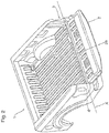
- a rotary damper 250 is incorporated to limit, or control, the speed at which the tailgate 2 is opened.
- Figure 7 depicts one example of the rotary damper 250 that is positioned within a housing for the first gear arrangement 13 and coupled to the first gear arrangement 13 of the control device 11.
- the rotary damper 250 may be coupled to the first gear arrangement 13 while being positioned outside the housing.
- the rotary damper 250 can similarly be positioned and coupled with the first gear arrangement 113 of the control device 100. For example, when the clutch arrangement 14, 114 is in the disengaged position, the tailgate 2 can be opened manually.
- the rotary damper 250 is coupled to the first gear arrangement 13, 113 to limit the velocity at which the tailgate 2 moves when it is being manually opened.
- the rotary damper 250 may be directly coupled with one or more gears of the first gear arrangement 13, 113.
- the rotary damper 250 may be indirectly coupled to the first gear arrangement 13, 113, for example, by way of a rack and pinion arrangement or any other suitable arrangement.
- the rotary damper 250 can limit the opening velocity of the tailgate 2 through the entire swing path of the tailgate 2, between the fully closed and fully opened positions, or through only a portion of the swing path of the tailgate 2.
- the rotary damper 250 may comprise an outer fixed body and an inner rotor that rotates within the outer fixed body.
- the inner rotor is coupled, either directly or indirectly, with one or more gears of the first gear assembly 13, 113.
- the speed at which the inner rotor rotates within the outer fixed body may be limited by a fluid that is present within the fixed outer body.
- the fluid can be positioned within a space between the outer fixed body and the inner rotor.
- the viscosity of the fluid and a damper metering orifice may determine the velocity at which the inner rotor rotates.
- the fluid may comprise silicone.
- other types of rotary dampers 250 may be used, such as friction based dampers and fluid shear based dampers. Limiting the rate at which the inner rotor rotates will limit the rotational rate of the first gear assembly 13, 113, which in turn will limit the velocity of the tail gate 2 when it is manually opened.
- the tailgate 2 can be removed from the truck box 1.
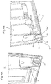
- Rotating the tailgate 2 to a predetermined release angle (shown as ⁇ in Figure 7 ) relative to the longitudinal axis of the truck box 1 (indicated as line Y in Figure 7 ) allows the drive arm 10 to release from the drive cup 9.
- a pulling force along the predetermined release angle ⁇ for example a manual pulling force
- the drive arm 10 passes through the open side 25.
- the drive cup 9 may rotate within a nonrotating outer collar 24' with an opening that aligns with the predetermined release angle (see Figure 4B ).
- the outer collar 24' prevents the male drive portion 6 from passing through the opening in the outer collar 24'.
- the male drive portion 6 may pass through the opening in the outer collar 24' and the male drive portion 6 is released.
- the tailgate 2 can be shifted laterally parallel to the axis of rotation (shown as line X) to release the circular arm 29 from the annular cup 23 and thus to release the tailgate 2 from the truck box 1.
- the electrical connector 28 can be disconnected either before or after releasing the drive arm 10 from the drive cup 9.
Landscapes
- Engineering & Computer Science (AREA)
- Mechanical Engineering (AREA)
- Chemical & Material Sciences (AREA)
- Combustion & Propulsion (AREA)
- Transportation (AREA)
- Power-Operated Mechanisms For Wings (AREA)
- Braking Arrangements (AREA)
- Motor Power Transmission Devices (AREA)
- Cooling, Air Intake And Gas Exhaust, And Fuel Tank Arrangements In Propulsion Units (AREA)
- Lock And Its Accessories (AREA)
Claims (7)
- Steuervorrichtung (100) für eine Fahrzeug-Heckklappe, aufweisend:a. eine Getriebeanordnung (113);b. einen Antriebsbecher (9), der mit der Getriebeanordnung (113) verbunden ist, wobei der Antriebsbecher (9) lösbar mit einer Heckklappe (1) des Fahrzeugs verbunden ist;c. eine Bremseinheit (130), die dazu eingerichtet ist, die Bewegung der Getriebeanordnung (113) anzuhalten oder zu verlangsamen;d. eine Kupplungsanordnung (114), die mit der Getriebeanordnung (113) verbunden ist, wobei die Kupplungsanordnung (114) zwischen einer eingekoppelten Position und einer ausgekoppelten Position bewegbar ist, so dass die Kupplungsanordnung (114) in der eingekoppelten Position die Getriebeanordnung (113) mit der Bremseinheit (130) koppelt und in der ausgekoppelten Position die Getriebeanordnung (113) und die Bremseinheit (130) nicht gekoppelt sind;e. einen Winkelbewegungssensor (127), der dazu eingerichtet ist, eine Änderung der Geschwindigkeit und Richtung der Bewegung der Zahnradanordnung (113) zu erfassen, wenn sich die Zahnradanordnung (113) dreht, und Heckklappenbewegungsinformationen über die Änderung zu erzeugen; undf. eine Steuerung (126), die dazu eingerichtet ist, die von dem Winkelbewegungssensor (127) gesendeten Informationen über die Heckklappenbewegung empfängt und der Kupplungsanordnung (114) befiehlt, sich auf der Grundlage der Information zwischen der eingekoppelten Position und der ausgekoppelten Position zu bewegen;g. wobei die Steuervorrichtung innerhalb der Heckklappe positionierbar ist; undh. einen Rotationsdämpfer (250), der mit der Getriebeanordnung (113) gekoppelt ist, wobei der Rotationsdämpfer (250) eine Drehrate der Getriebeanordnung (113) begrenzt, wenn sich die Kupplungsanordnung (114) in der ausgekoppelten Position befindet.
- Steuervorrichtung nach Anspruch 1,
wobei, wenn die Änderung eine Geschwindigkeitsänderung ist und einen vorbestimmten Wert überschreitet, die Kupplungsanordnung (114) in die eingekoppelte Position gebracht wird, um die Bremseinheit (130) mit der Getriebeanordnung (113) zu koppeln, und, wenn die Änderung eine Richtungsänderung ist, die Kupplungsanordnung (114) in die ausgekoppelte Position gebracht wird, um die Bremseinheit (130) von der Getriebeanordnung (113) zu trennen. - Fahrzeug-Heckklappe mit einer Kammer zur Aufnahme einer Steuervorrichtung (100) nach einem der Ansprüche 1 oder 2, wobei die Steuervorrichtung (100) innerhalb der Kammer angebracht ist.
- Fahrzeug-Heckklappe nach Anspruch 3, weiterhin aufweisend einen elektronischen Verbinder (28), der dazu eingerichtet ist, eine elektrische Stromversorgung an die Steuervorrichtung (100) zu verteilen.
- Fahrzeug-Heckklappe nach Anspruch 4,
wobei der elektronische Verbinder (28) reversibel mit der Steuervorrichtung (100) verbunden ist und der elektronische Verbinder (28) dazu eingerichtet ist, elektronische Signale von einer Benutzerschnittstelle an die Steuervorrichtung (100) weiterzuleiten. - Verfahren zum Anhalten oder Abbremsen einer sich drehenden Fahrzeug-Heckklappe, wobei die Heckklappe die Steuereinrichtung (100) nach einem der Ansprüche 1 oder 2 aufweist,
wobei das Verfahren die folgenden Schritte umfasst:(a) Erfassen, durch den Winkelbewegungssensor (127), einer Änderung der Winkelbewegung der Getriebeanordnung (113), wenn die Getriebeanordnung (113) mit der Drehung der Fahrzeugheckklappe rotiert,(b) Erzeugen und Senden eines Drehgeschwindigkeitssignals durch den Winkelbewegungssensor (127) an einen Controller (126), wobei der Controller (126) so programmiert ist, folgende Schritte auszuführen:i. Empfangen und Vergleichen des Signals mit einem voreingestellten Wert, um zu bestimmen, ob es eine Änderung der Geschwindigkeit gibt;ii. Erzeugen, wenn eine Änderung vorliegt, eines Wertfehlersignals und Vergleichen des Wertfehlersignals mit einem voreingestellten Fehlerwert; undiii. Senden, wenn das Wertfehlersignal größer als der voreingestellte Fehlerwert ist, eines Befehls, um die Kupplungsanordnung (114) in die eingekoppelte Position zu bringen, so dass die Getriebeanordnung (113) mit der Bremseinheit (130) gekoppelt wird, um die Drehung der Getriebeanordnung (113) und nacheinander der Fahrzeugheckklappe anzuhalten oder zu verlangsamen. - Verfahren nach Anspruch 6, wobei das Verfahren weiterhin die folgenden Schritte aufweist:(c) weiterhin Erfassen, durch den Winkelbewegungssensor (127), einer Änderung der Richtung der Winkelbewegung der Getriebeanordnung (113);(d) Erzeugen, wenn sich die Getriebeanordnung (113) in eine entgegengesetzte Richtung bewegt, und Senden eines Freigabesignals an die Steuerung (126); und(e) Senden, durch die Steuerung (126), eines Steuerungs-Auskoppelsignals, um die Bremseinheit (130) von der Getriebeanordnung (113) zu trennen, indem die Kupplungsanordnung (114) in die ausgekoppelte Position gebracht wird, wodurch die Getriebeanordnung (113) und nacheinander die Bewegung der Fahrzeugheckklappe ermöglicht wird.
Applications Claiming Priority (3)
| Application Number | Priority Date | Filing Date | Title |
|---|---|---|---|
| CA2798237A CA2798237A1 (en) | 2012-12-07 | 2012-12-07 | Decouplable power drive for tailgates |
| EP13860066.3A EP2928762B1 (de) | 2012-12-07 | 2013-12-06 | Entkoppelbarer kraftantrieb für heckklappen |
| PCT/CA2013/050937 WO2014085932A1 (en) | 2012-12-07 | 2013-12-06 | Decouplable power drive for tailgates |
Related Parent Applications (2)
| Application Number | Title | Priority Date | Filing Date |
|---|---|---|---|
| EP13860066.3A Division-Into EP2928762B1 (de) | 2012-12-07 | 2013-12-06 | Entkoppelbarer kraftantrieb für heckklappen |
| EP13860066.3A Division EP2928762B1 (de) | 2012-12-07 | 2013-12-06 | Entkoppelbarer kraftantrieb für heckklappen |
Publications (2)
| Publication Number | Publication Date |
|---|---|
| EP3299261A1 EP3299261A1 (de) | 2018-03-28 |
| EP3299261B1 true EP3299261B1 (de) | 2021-01-27 |
Family
ID=50877730
Family Applications (2)
| Application Number | Title | Priority Date | Filing Date |
|---|---|---|---|
| EP13860066.3A Active EP2928762B1 (de) | 2012-12-07 | 2013-12-06 | Entkoppelbarer kraftantrieb für heckklappen |
| EP17194469.7A Active EP3299261B1 (de) | 2012-12-07 | 2013-12-06 | Entkoppelbarer kraftantrieb für heckklappen |
Family Applications Before (1)
| Application Number | Title | Priority Date | Filing Date |
|---|---|---|---|
| EP13860066.3A Active EP2928762B1 (de) | 2012-12-07 | 2013-12-06 | Entkoppelbarer kraftantrieb für heckklappen |
Country Status (12)
| Country | Link |
|---|---|
| US (1) | US9797180B2 (de) |
| EP (2) | EP2928762B1 (de) |
| JP (1) | JP6162816B2 (de) |
| KR (1) | KR101913703B1 (de) |
| CN (2) | CN107380269B (de) |
| AU (2) | AU2013354826B2 (de) |
| BR (2) | BR112015013007B1 (de) |
| CA (3) | CA2798237A1 (de) |
| ES (2) | ES2830771T3 (de) |
| MX (1) | MX358247B (de) |
| RU (1) | RU2608941C2 (de) |
| WO (1) | WO2014085932A1 (de) |
Families Citing this family (27)
| Publication number | Priority date | Publication date | Assignee | Title |
|---|---|---|---|---|
| US9587421B1 (en) * | 2015-10-28 | 2017-03-07 | Dura Operating, Llc | Dual clutch cable control system |
| US9796429B1 (en) * | 2017-01-23 | 2017-10-24 | Ford Global Technologies, Llc | Tailgate work surface |
| US9923294B1 (en) * | 2017-01-23 | 2018-03-20 | Ford Global Technologies, Llc | Electrical connector for a removable tailgate |
| US10343728B2 (en) * | 2017-02-16 | 2019-07-09 | Ford Global Technolgies, Llc | Powered hinge assembly and powered tailgate assembly incorporating that powered hinge assembly |
| US10293868B2 (en) | 2017-03-01 | 2019-05-21 | Ford Global Technologies, Llc | Removable tailgate with locking hinge |
| US10731395B2 (en) | 2017-03-15 | 2020-08-04 | Ford Global Technologies, Llc | Smart hinge assembly for a tailgate of a motor vehicle |
| CN108891332B (zh) * | 2018-06-20 | 2019-12-20 | 安徽华兴车辆有限公司 | 一种新型自卸车后门的翻启装置 |
| US10577030B1 (en) | 2018-08-07 | 2020-03-03 | Ford Global Technologies, Llc | Powered tailgate removal assembly and method |
| US10927581B2 (en) | 2018-10-03 | 2021-02-23 | Ford Global Technologies, Llc | Tailgate step stowage assistance |
| US11098518B2 (en) * | 2018-12-13 | 2021-08-24 | Fca Us Llc | Power tailgate motor mount cartridge assembly |
| US11161555B2 (en) | 2019-09-06 | 2021-11-02 | Banks Morrison Innovations Llc | Tailgate deactivation system |
| US10850707B1 (en) | 2019-11-19 | 2020-12-01 | Honda Motor Co., Ltd. | Tailgate locking system and method of operating |
| DE102020204543A1 (de) * | 2020-04-08 | 2021-10-14 | Vitesco Technologies GmbH | Fahrzeugtüraktuator, Fahrzeugtür und Fahrzeug |
| US11535309B2 (en) | 2020-05-26 | 2022-12-27 | AISIN Technical Center of America, Inc. | Hinge assembly for a power tailgate system |
| EP3919712B1 (de) | 2020-06-01 | 2024-06-12 | Soluciones Conceptuales E Innovacion S.L. | Urbaner abfallbehälter |
| DE112021003115T5 (de) * | 2020-06-04 | 2023-05-25 | Multimatic Inc. | Klappbare fahrzeug-heckklappe |
| US12195098B2 (en) | 2020-07-29 | 2025-01-14 | Mitsui Kinzoku Act Corporation | Opening/closing mechanism for opening/closing member |
| DE102021200269A1 (de) * | 2021-01-13 | 2022-07-14 | Brose Fahrzeugteile Se & Co. Kommanditgesellschaft, Bamberg | Verfahren zum Betrieb einer Ladeklappe eines Kraftfahrzeugs |
| CN113353160A (zh) * | 2021-06-17 | 2021-09-07 | 十堰安远专用汽车有限公司 | 一种轻卡车厢 |
| CN113585907B (zh) * | 2021-09-01 | 2025-03-28 | 深圳坚威科技实业有限公司 | 一种智能门窗用启闭锁一体动力盒 |
| KR20230039937A (ko) | 2021-09-15 | 2023-03-22 | 현대자동차주식회사 | 차량의 리어 범퍼 구조 |
| CN114111749B (zh) * | 2021-10-29 | 2022-12-02 | 江苏凯卓立液压设备有限公司 | 一种利用陀螺仪判断和计算液压尾板动作的系统及方法 |
| JP7776743B2 (ja) * | 2021-12-10 | 2025-11-27 | シンフォニアテクノロジー株式会社 | アオリ衝突検知システム、アオリ駆動機構 |
| JP2023086159A (ja) * | 2021-12-10 | 2023-06-22 | シンフォニアテクノロジー株式会社 | アオリ衝突検知システム、アオリ駆動機構 |
| JP7795078B2 (ja) * | 2021-12-20 | 2026-01-07 | シンフォニアテクノロジー株式会社 | アオリ角度推定システム、アオリ駆動機構 |
| US12168896B2 (en) * | 2022-08-02 | 2024-12-17 | Toyota Motor Engineering & Manufacturing North America, Inc. | Backdoor assemblies for vehicles |
| CN119239778A (zh) * | 2024-10-23 | 2025-01-03 | 中联重科股份有限公司 | 一种车辆后防护栏及制动系统 |
Citations (1)
| Publication number | Priority date | Publication date | Assignee | Title |
|---|---|---|---|---|
| WO2005111354A1 (de) * | 2004-05-11 | 2005-11-24 | Valeo Sicherheitssysteme Gmbh | Verfahren zum automatischen betätigen einer kraftfahrzeugtür |
Family Cites Families (23)
| Publication number | Priority date | Publication date | Assignee | Title |
|---|---|---|---|---|
| US2893727A (en) | 1956-04-27 | 1959-07-07 | Gen Motors Corp | Power actuated closures |
| JPS6171771U (de) * | 1984-10-17 | 1986-05-16 | ||
| JPH0624181U (ja) * | 1992-08-28 | 1994-03-29 | 日野自動車工業株式会社 | 車両用開閉体のヒンジ装置 |
| JPH0628160U (ja) * | 1992-09-08 | 1994-04-15 | 日野自動車工業株式会社 | 車両の開閉体用ヒンジ装置 |
| US6217097B1 (en) * | 1999-07-21 | 2001-04-17 | Delphi Technologies, Inc. | Power operated tailgate |
| JP3736431B2 (ja) * | 2001-11-13 | 2006-01-18 | 日産自動車株式会社 | オートスライドドア制御装置 |
| US6796592B1 (en) * | 2003-03-12 | 2004-09-28 | M & C Corporation | Tailgate counterbalancing hinge |
| US6874837B2 (en) * | 2003-06-25 | 2005-04-05 | Ford Global Technologies, Llc | Lift assisted tailgate system for automotive vehicle |
| DE10331633A1 (de) * | 2003-07-12 | 2005-02-03 | Valeo Sicherheitssysteme Gmbh | Antrieb zur automatischen Betätigung einer Fahrzeugtür |
| US20060181108A1 (en) | 2003-09-29 | 2006-08-17 | Cleland Terry P | Low-mounted powered opening system and control mechanism |
| JP4262578B2 (ja) * | 2003-11-17 | 2009-05-13 | 株式会社ミツバ | バックドア自動開閉装置 |
| JP3987976B2 (ja) * | 2003-11-25 | 2007-10-10 | 自動車電機工業株式会社 | バックドア自動開閉装置 |
| MXPA06010231A (es) | 2004-03-10 | 2008-03-10 | M & C Corp | Articulacion de equilibrio para puerta trasera. |
| FR2885158A1 (fr) * | 2005-04-28 | 2006-11-03 | Arvinmeritor Light Vehicle Sys | Vehicule avec un hayon |
| DE102005020308A1 (de) * | 2005-04-30 | 2006-11-02 | Blaut Management + Marketing Gmbh | Vorrichtung zum Öffnen und Schließen einer Karosserieklappe |
| DE102005030053B4 (de) | 2005-06-27 | 2013-05-29 | Stabilus Gmbh | Antrieb zum Verschwenken einer an eine Karosserie eines Fahrzeugs angeordnete Klappe |
| US7695043B2 (en) * | 2005-07-21 | 2010-04-13 | Zagoroff Dimiter S | Truck tailgate with motion control devices |
| US20070152471A1 (en) * | 2005-07-21 | 2007-07-05 | Zagoroff Dimiter S | Truck tailgate with internal motion control devices |
| US7293821B2 (en) * | 2005-11-10 | 2007-11-13 | Paul Tran | Airflow control tailgate |
| US7287803B2 (en) * | 2005-12-08 | 2007-10-30 | Hi-Lex Corporation | Rotating cable tailgate actuator |
| US7654600B2 (en) * | 2007-02-20 | 2010-02-02 | Ford Global Technologies, Llc | Vehicle tailgate movement assist mechanism using lever driven rotary damper |
| DE102008003580B4 (de) * | 2008-01-09 | 2011-11-17 | Continental Automotive Gmbh | Verfahren und Vorrichtung zum Ermitteln einer Referenzposition eines von einem Elektromotor bewegten Schließteils |
| RU2437777C1 (ru) * | 2010-07-06 | 2011-12-27 | Андрей Семёнович Орлов | Устройство для открывания задней двери кузова автомобиля |
-
2012
- 2012-12-07 CA CA2798237A patent/CA2798237A1/en not_active Abandoned
-
2013
- 2013-12-06 AU AU2013354826A patent/AU2013354826B2/en not_active Ceased
- 2013-12-06 RU RU2015126848A patent/RU2608941C2/ru active
- 2013-12-06 ES ES13860066T patent/ES2830771T3/es active Active
- 2013-12-06 KR KR1020157016355A patent/KR101913703B1/ko active Active
- 2013-12-06 EP EP13860066.3A patent/EP2928762B1/de active Active
- 2013-12-06 MX MX2015007163A patent/MX358247B/es active IP Right Grant
- 2013-12-06 WO PCT/CA2013/050937 patent/WO2014085932A1/en not_active Ceased
- 2013-12-06 ES ES17194469T patent/ES2865508T3/es active Active
- 2013-12-06 US US14/649,243 patent/US9797180B2/en active Active
- 2013-12-06 CN CN201710361924.8A patent/CN107380269B/zh active Active
- 2013-12-06 CA CA2893448A patent/CA2893448C/en active Active
- 2013-12-06 CA CA2971192A patent/CA2971192C/en active Active
- 2013-12-06 BR BR112015013007-0A patent/BR112015013007B1/pt active IP Right Grant
- 2013-12-06 JP JP2015545610A patent/JP6162816B2/ja active Active
- 2013-12-06 EP EP17194469.7A patent/EP3299261B1/de active Active
- 2013-12-06 CN CN201380064058.6A patent/CN104837718B/zh active Active
- 2013-12-06 BR BR122022014047-5A patent/BR122022014047B1/pt active IP Right Grant
-
2017
- 2017-06-22 AU AU2017204224A patent/AU2017204224A1/en not_active Abandoned
Patent Citations (1)
| Publication number | Priority date | Publication date | Assignee | Title |
|---|---|---|---|---|
| WO2005111354A1 (de) * | 2004-05-11 | 2005-11-24 | Valeo Sicherheitssysteme Gmbh | Verfahren zum automatischen betätigen einer kraftfahrzeugtür |
Also Published As
Similar Documents
| Publication | Publication Date | Title |
|---|---|---|
| CA2971192C (en) | Decouplable power drive for tailgates | |
| US9353566B2 (en) | Power door actuation system | |
| US10655378B2 (en) | Power side door actuator with rotating drive nut | |
| US20190112859A1 (en) | Power door with toothed rod crank mechanism | |
| CN115075686A (zh) | 用于伺服控制的动力门致动器的分布式控制系统 | |
| CN109779439B (zh) | 车辆滑动门的马达驱动装置 | |
| CN204266735U (zh) | 一种车门限位装置及汽车 | |
| KR102040051B1 (ko) | 초음파 센서를 이용한 차량 도어 자동 개폐 장치 | |
| US7698855B2 (en) | Sliding-door opening control apparatus | |
| WO2018023096A1 (en) | Automatic vehicle closure system | |
| CN101660382A (zh) | 背门电动系统 | |
| CN101223329A (zh) | 冷藏和/或冷冻设备 | |
| KR101080759B1 (ko) | 자동차용 도어 자동개폐장치 | |
| CN120425964A (zh) | 动力闭合构件系统、对其进行控制的方法以及对其控制系统进行配置的方法 | |
| KR101755493B1 (ko) | 전동식 테일게이트의 제어방법 및 제어시스템 | |
| KR101228870B1 (ko) | 트렁크용 개폐장치 | |
| TW200944398A (en) | Back door electric system |
Legal Events
| Date | Code | Title | Description |
|---|---|---|---|
| PUAI | Public reference made under article 153(3) epc to a published international application that has entered the european phase |
Free format text: ORIGINAL CODE: 0009012 |
|
| STAA | Information on the status of an ep patent application or granted ep patent |
Free format text: STATUS: THE APPLICATION HAS BEEN PUBLISHED |
|
| AC | Divisional application: reference to earlier application |
Ref document number: 2928762 Country of ref document: EP Kind code of ref document: P |
|
| AK | Designated contracting states |
Kind code of ref document: A1 Designated state(s): AL AT BE BG CH CY CZ DE DK EE ES FI FR GB GR HR HU IE IS IT LI LT LU LV MC MK MT NL NO PL PT RO RS SE SI SK SM TR |
|
| AX | Request for extension of the european patent |
Extension state: BA ME |
|
| STAA | Information on the status of an ep patent application or granted ep patent |
Free format text: STATUS: REQUEST FOR EXAMINATION WAS MADE |
|
| 17P | Request for examination filed |
Effective date: 20180712 |
|
| RBV | Designated contracting states (corrected) |
Designated state(s): AL AT BE BG CH CY CZ DE DK EE ES FI FR GB GR HR HU IE IS IT LI LT LU LV MC MK MT NL NO PL PT RO RS SE SI SK SM TR |
|
| STAA | Information on the status of an ep patent application or granted ep patent |
Free format text: STATUS: EXAMINATION IS IN PROGRESS |
|
| 17Q | First examination report despatched |
Effective date: 20190408 |
|
| RIC1 | Information provided on ipc code assigned before grant |
Ipc: E05F 5/00 20170101ALI20200714BHEP Ipc: E05F 15/614 20150101ALI20200714BHEP Ipc: E05D 7/10 20060101ALN20200714BHEP Ipc: B62D 33/033 20060101AFI20200714BHEP |
|
| GRAP | Despatch of communication of intention to grant a patent |
Free format text: ORIGINAL CODE: EPIDOSNIGR1 |
|
| STAA | Information on the status of an ep patent application or granted ep patent |
Free format text: STATUS: GRANT OF PATENT IS INTENDED |
|
| INTG | Intention to grant announced |
Effective date: 20200901 |
|
| GRAS | Grant fee paid |
Free format text: ORIGINAL CODE: EPIDOSNIGR3 |
|
| GRAA | (expected) grant |
Free format text: ORIGINAL CODE: 0009210 |
|
| STAA | Information on the status of an ep patent application or granted ep patent |
Free format text: STATUS: THE PATENT HAS BEEN GRANTED |
|
| AC | Divisional application: reference to earlier application |
Ref document number: 2928762 Country of ref document: EP Kind code of ref document: P |
|
| AK | Designated contracting states |
Kind code of ref document: B1 Designated state(s): AL AT BE BG CH CY CZ DE DK EE ES FI FR GB GR HR HU IE IS IT LI LT LU LV MC MK MT NL NO PL PT RO RS SE SI SK SM TR |
|
| REG | Reference to a national code |
Ref country code: GB Ref legal event code: FG4D |
|
| REG | Reference to a national code |
Ref country code: CH Ref legal event code: EP |
|
| REG | Reference to a national code |
Ref country code: AT Ref legal event code: REF Ref document number: 1358106 Country of ref document: AT Kind code of ref document: T Effective date: 20210215 |
|
| REG | Reference to a national code |
Ref country code: IE Ref legal event code: FG4D |
|
| REG | Reference to a national code |
Ref country code: DE Ref legal event code: R096 Ref document number: 602013075547 Country of ref document: DE |
|
| REG | Reference to a national code |
Ref country code: SE Ref legal event code: TRGR |
|
| REG | Reference to a national code |
Ref country code: NL Ref legal event code: MP Effective date: 20210127 |
|
| REG | Reference to a national code |
Ref country code: LT Ref legal event code: MG9D |
|
| REG | Reference to a national code |
Ref country code: AT Ref legal event code: MK05 Ref document number: 1358106 Country of ref document: AT Kind code of ref document: T Effective date: 20210127 |
|
| PG25 | Lapsed in a contracting state [announced via postgrant information from national office to epo] |
Ref country code: PT Free format text: LAPSE BECAUSE OF FAILURE TO SUBMIT A TRANSLATION OF THE DESCRIPTION OR TO PAY THE FEE WITHIN THE PRESCRIBED TIME-LIMIT Effective date: 20210527 Ref country code: NO Free format text: LAPSE BECAUSE OF FAILURE TO SUBMIT A TRANSLATION OF THE DESCRIPTION OR TO PAY THE FEE WITHIN THE PRESCRIBED TIME-LIMIT Effective date: 20210427 Ref country code: GR Free format text: LAPSE BECAUSE OF FAILURE TO SUBMIT A TRANSLATION OF THE DESCRIPTION OR TO PAY THE FEE WITHIN THE PRESCRIBED TIME-LIMIT Effective date: 20210428 Ref country code: HR Free format text: LAPSE BECAUSE OF FAILURE TO SUBMIT A TRANSLATION OF THE DESCRIPTION OR TO PAY THE FEE WITHIN THE PRESCRIBED TIME-LIMIT Effective date: 20210127 Ref country code: FI Free format text: LAPSE BECAUSE OF FAILURE TO SUBMIT A TRANSLATION OF THE DESCRIPTION OR TO PAY THE FEE WITHIN THE PRESCRIBED TIME-LIMIT Effective date: 20210127 Ref country code: BG Free format text: LAPSE BECAUSE OF FAILURE TO SUBMIT A TRANSLATION OF THE DESCRIPTION OR TO PAY THE FEE WITHIN THE PRESCRIBED TIME-LIMIT Effective date: 20210427 Ref country code: LT Free format text: LAPSE BECAUSE OF FAILURE TO SUBMIT A TRANSLATION OF THE DESCRIPTION OR TO PAY THE FEE WITHIN THE PRESCRIBED TIME-LIMIT Effective date: 20210127 |
|
| PG25 | Lapsed in a contracting state [announced via postgrant information from national office to epo] |
Ref country code: PL Free format text: LAPSE BECAUSE OF FAILURE TO SUBMIT A TRANSLATION OF THE DESCRIPTION OR TO PAY THE FEE WITHIN THE PRESCRIBED TIME-LIMIT Effective date: 20210127 Ref country code: RS Free format text: LAPSE BECAUSE OF FAILURE TO SUBMIT A TRANSLATION OF THE DESCRIPTION OR TO PAY THE FEE WITHIN THE PRESCRIBED TIME-LIMIT Effective date: 20210127 Ref country code: LV Free format text: LAPSE BECAUSE OF FAILURE TO SUBMIT A TRANSLATION OF THE DESCRIPTION OR TO PAY THE FEE WITHIN THE PRESCRIBED TIME-LIMIT Effective date: 20210127 Ref country code: AT Free format text: LAPSE BECAUSE OF FAILURE TO SUBMIT A TRANSLATION OF THE DESCRIPTION OR TO PAY THE FEE WITHIN THE PRESCRIBED TIME-LIMIT Effective date: 20210127 |
|
| PG25 | Lapsed in a contracting state [announced via postgrant information from national office to epo] |
Ref country code: IS Free format text: LAPSE BECAUSE OF FAILURE TO SUBMIT A TRANSLATION OF THE DESCRIPTION OR TO PAY THE FEE WITHIN THE PRESCRIBED TIME-LIMIT Effective date: 20210527 |
|
| REG | Reference to a national code |
Ref country code: ES Ref legal event code: FG2A Ref document number: 2865508 Country of ref document: ES Kind code of ref document: T3 Effective date: 20211015 |
|
| REG | Reference to a national code |
Ref country code: DE Ref legal event code: R097 Ref document number: 602013075547 Country of ref document: DE |
|
| PG25 | Lapsed in a contracting state [announced via postgrant information from national office to epo] |
Ref country code: SM Free format text: LAPSE BECAUSE OF FAILURE TO SUBMIT A TRANSLATION OF THE DESCRIPTION OR TO PAY THE FEE WITHIN THE PRESCRIBED TIME-LIMIT Effective date: 20210127 Ref country code: EE Free format text: LAPSE BECAUSE OF FAILURE TO SUBMIT A TRANSLATION OF THE DESCRIPTION OR TO PAY THE FEE WITHIN THE PRESCRIBED TIME-LIMIT Effective date: 20210127 Ref country code: CZ Free format text: LAPSE BECAUSE OF FAILURE TO SUBMIT A TRANSLATION OF THE DESCRIPTION OR TO PAY THE FEE WITHIN THE PRESCRIBED TIME-LIMIT Effective date: 20210127 |
|
| PG25 | Lapsed in a contracting state [announced via postgrant information from national office to epo] |
Ref country code: DK Free format text: LAPSE BECAUSE OF FAILURE TO SUBMIT A TRANSLATION OF THE DESCRIPTION OR TO PAY THE FEE WITHIN THE PRESCRIBED TIME-LIMIT Effective date: 20210127 Ref country code: RO Free format text: LAPSE BECAUSE OF FAILURE TO SUBMIT A TRANSLATION OF THE DESCRIPTION OR TO PAY THE FEE WITHIN THE PRESCRIBED TIME-LIMIT Effective date: 20210127 Ref country code: SK Free format text: LAPSE BECAUSE OF FAILURE TO SUBMIT A TRANSLATION OF THE DESCRIPTION OR TO PAY THE FEE WITHIN THE PRESCRIBED TIME-LIMIT Effective date: 20210127 |
|
| PLBE | No opposition filed within time limit |
Free format text: ORIGINAL CODE: 0009261 |
|
| STAA | Information on the status of an ep patent application or granted ep patent |
Free format text: STATUS: NO OPPOSITION FILED WITHIN TIME LIMIT |
|
| 26N | No opposition filed |
Effective date: 20211028 |
|
| PG25 | Lapsed in a contracting state [announced via postgrant information from national office to epo] |
Ref country code: AL Free format text: LAPSE BECAUSE OF FAILURE TO SUBMIT A TRANSLATION OF THE DESCRIPTION OR TO PAY THE FEE WITHIN THE PRESCRIBED TIME-LIMIT Effective date: 20210127 |
|
| PG25 | Lapsed in a contracting state [announced via postgrant information from national office to epo] |
Ref country code: SI Free format text: LAPSE BECAUSE OF FAILURE TO SUBMIT A TRANSLATION OF THE DESCRIPTION OR TO PAY THE FEE WITHIN THE PRESCRIBED TIME-LIMIT Effective date: 20210127 |
|
| PG25 | Lapsed in a contracting state [announced via postgrant information from national office to epo] |
Ref country code: IS Free format text: LAPSE BECAUSE OF FAILURE TO SUBMIT A TRANSLATION OF THE DESCRIPTION OR TO PAY THE FEE WITHIN THE PRESCRIBED TIME-LIMIT Effective date: 20210527 |
|
| PG25 | Lapsed in a contracting state [announced via postgrant information from national office to epo] |
Ref country code: MC Free format text: LAPSE BECAUSE OF FAILURE TO SUBMIT A TRANSLATION OF THE DESCRIPTION OR TO PAY THE FEE WITHIN THE PRESCRIBED TIME-LIMIT Effective date: 20210127 |
|
| REG | Reference to a national code |
Ref country code: CH Ref legal event code: PL |
|
| REG | Reference to a national code |
Ref country code: BE Ref legal event code: MM Effective date: 20211231 |
|
| PG25 | Lapsed in a contracting state [announced via postgrant information from national office to epo] |
Ref country code: LU Free format text: LAPSE BECAUSE OF NON-PAYMENT OF DUE FEES Effective date: 20211206 Ref country code: IE Free format text: LAPSE BECAUSE OF NON-PAYMENT OF DUE FEES Effective date: 20211206 |
|
| PG25 | Lapsed in a contracting state [announced via postgrant information from national office to epo] |
Ref country code: BE Free format text: LAPSE BECAUSE OF NON-PAYMENT OF DUE FEES Effective date: 20211231 |
|
| PG25 | Lapsed in a contracting state [announced via postgrant information from national office to epo] |
Ref country code: LI Free format text: LAPSE BECAUSE OF NON-PAYMENT OF DUE FEES Effective date: 20211231 Ref country code: CH Free format text: LAPSE BECAUSE OF NON-PAYMENT OF DUE FEES Effective date: 20211231 |
|
| PG25 | Lapsed in a contracting state [announced via postgrant information from national office to epo] |
Ref country code: HU Free format text: LAPSE BECAUSE OF FAILURE TO SUBMIT A TRANSLATION OF THE DESCRIPTION OR TO PAY THE FEE WITHIN THE PRESCRIBED TIME-LIMIT; INVALID AB INITIO Effective date: 20131206 |
|
| P01 | Opt-out of the competence of the unified patent court (upc) registered |
Effective date: 20230509 |
|
| PG25 | Lapsed in a contracting state [announced via postgrant information from national office to epo] |
Ref country code: NL Free format text: LAPSE BECAUSE OF NON-PAYMENT OF DUE FEES Effective date: 20210127 Ref country code: CY Free format text: LAPSE BECAUSE OF FAILURE TO SUBMIT A TRANSLATION OF THE DESCRIPTION OR TO PAY THE FEE WITHIN THE PRESCRIBED TIME-LIMIT Effective date: 20210127 |
|
| PG25 | Lapsed in a contracting state [announced via postgrant information from national office to epo] |
Ref country code: MK Free format text: LAPSE BECAUSE OF FAILURE TO SUBMIT A TRANSLATION OF THE DESCRIPTION OR TO PAY THE FEE WITHIN THE PRESCRIBED TIME-LIMIT Effective date: 20210127 |
|
| PG25 | Lapsed in a contracting state [announced via postgrant information from national office to epo] |
Ref country code: MT Free format text: LAPSE BECAUSE OF FAILURE TO SUBMIT A TRANSLATION OF THE DESCRIPTION OR TO PAY THE FEE WITHIN THE PRESCRIBED TIME-LIMIT Effective date: 20210127 |
|
| PGFP | Annual fee paid to national office [announced via postgrant information from national office to epo] |
Ref country code: FR Payment date: 20250930 Year of fee payment: 13 |
|
| PGFP | Annual fee paid to national office [announced via postgrant information from national office to epo] |
Ref country code: DE Payment date: 20250930 Year of fee payment: 13 |
|
| PGFP | Annual fee paid to national office [announced via postgrant information from national office to epo] |
Ref country code: GB Payment date: 20251001 Year of fee payment: 13 |
|
| PGFP | Annual fee paid to national office [announced via postgrant information from national office to epo] |
Ref country code: IT Payment date: 20251121 Year of fee payment: 13 |
|
| PGFP | Annual fee paid to national office [announced via postgrant information from national office to epo] |
Ref country code: TR Payment date: 20251203 Year of fee payment: 13 |
|
| PGFP | Annual fee paid to national office [announced via postgrant information from national office to epo] |
Ref country code: SE Payment date: 20251001 Year of fee payment: 13 |
|
| PGFP | Annual fee paid to national office [announced via postgrant information from national office to epo] |
Ref country code: ES Payment date: 20260116 Year of fee payment: 13 |