EP3299151B1 - Kopf für einen dreidimensionalen drucker zur ausgabe mehrerer formschmelzlösungen und dreidimensionaler drucker damit - Google Patents
Kopf für einen dreidimensionalen drucker zur ausgabe mehrerer formschmelzlösungen und dreidimensionaler drucker damit Download PDFInfo
- Publication number
- EP3299151B1 EP3299151B1 EP16901165.7A EP16901165A EP3299151B1 EP 3299151 B1 EP3299151 B1 EP 3299151B1 EP 16901165 A EP16901165 A EP 16901165A EP 3299151 B1 EP3299151 B1 EP 3299151B1
- Authority
- EP
- European Patent Office
- Prior art keywords
- molding
- nozzle
- melt
- printer head
- filament
- Prior art date
- Legal status (The legal status is an assumption and is not a legal conclusion. Google has not performed a legal analysis and makes no representation as to the accuracy of the status listed.)
- Active
Links
Images

Classifications
-
- B—PERFORMING OPERATIONS; TRANSPORTING
- B29—WORKING OF PLASTICS; WORKING OF SUBSTANCES IN A PLASTIC STATE IN GENERAL
- B29C—SHAPING OR JOINING OF PLASTICS; SHAPING OF MATERIAL IN A PLASTIC STATE, NOT OTHERWISE PROVIDED FOR; AFTER-TREATMENT OF THE SHAPED PRODUCTS, e.g. REPAIRING
- B29C64/00—Additive manufacturing, i.e. manufacturing of three-dimensional [3D] objects by additive deposition, additive agglomeration or additive layering, e.g. by 3D printing, stereolithography or selective laser sintering
- B29C64/20—Apparatus for additive manufacturing; Details thereof or accessories therefor
- B29C64/205—Means for applying layers
- B29C64/209—Heads; Nozzles
-
- B—PERFORMING OPERATIONS; TRANSPORTING
- B29—WORKING OF PLASTICS; WORKING OF SUBSTANCES IN A PLASTIC STATE IN GENERAL
- B29C—SHAPING OR JOINING OF PLASTICS; SHAPING OF MATERIAL IN A PLASTIC STATE, NOT OTHERWISE PROVIDED FOR; AFTER-TREATMENT OF THE SHAPED PRODUCTS, e.g. REPAIRING
- B29C48/00—Extrusion moulding, i.e. expressing the moulding material through a die or nozzle which imparts the desired form; Apparatus therefor
- B29C48/03—Extrusion moulding, i.e. expressing the moulding material through a die or nozzle which imparts the desired form; Apparatus therefor characterised by the shape of the extruded material at extrusion
- B29C48/05—Filamentary, e.g. strands
-
- B—PERFORMING OPERATIONS; TRANSPORTING
- B29—WORKING OF PLASTICS; WORKING OF SUBSTANCES IN A PLASTIC STATE IN GENERAL
- B29C—SHAPING OR JOINING OF PLASTICS; SHAPING OF MATERIAL IN A PLASTIC STATE, NOT OTHERWISE PROVIDED FOR; AFTER-TREATMENT OF THE SHAPED PRODUCTS, e.g. REPAIRING
- B29C48/00—Extrusion moulding, i.e. expressing the moulding material through a die or nozzle which imparts the desired form; Apparatus therefor
- B29C48/03—Extrusion moulding, i.e. expressing the moulding material through a die or nozzle which imparts the desired form; Apparatus therefor characterised by the shape of the extruded material at extrusion
- B29C48/12—Articles with an irregular circumference when viewed in cross-section, e.g. window profiles
-
- B—PERFORMING OPERATIONS; TRANSPORTING
- B29—WORKING OF PLASTICS; WORKING OF SUBSTANCES IN A PLASTIC STATE IN GENERAL
- B29C—SHAPING OR JOINING OF PLASTICS; SHAPING OF MATERIAL IN A PLASTIC STATE, NOT OTHERWISE PROVIDED FOR; AFTER-TREATMENT OF THE SHAPED PRODUCTS, e.g. REPAIRING
- B29C48/00—Extrusion moulding, i.e. expressing the moulding material through a die or nozzle which imparts the desired form; Apparatus therefor
- B29C48/25—Component parts, details or accessories; Auxiliary operations
- B29C48/285—Feeding the extrusion material to the extruder
- B29C48/288—Feeding the extrusion material to the extruder in solid form, e.g. powder or granules
-
- B—PERFORMING OPERATIONS; TRANSPORTING
- B29—WORKING OF PLASTICS; WORKING OF SUBSTANCES IN A PLASTIC STATE IN GENERAL
- B29C—SHAPING OR JOINING OF PLASTICS; SHAPING OF MATERIAL IN A PLASTIC STATE, NOT OTHERWISE PROVIDED FOR; AFTER-TREATMENT OF THE SHAPED PRODUCTS, e.g. REPAIRING
- B29C48/00—Extrusion moulding, i.e. expressing the moulding material through a die or nozzle which imparts the desired form; Apparatus therefor
- B29C48/25—Component parts, details or accessories; Auxiliary operations
- B29C48/30—Extrusion nozzles or dies
- B29C48/345—Extrusion nozzles comprising two or more adjacently arranged ports, for simultaneously extruding multiple strands, e.g. for pelletising
-
- B—PERFORMING OPERATIONS; TRANSPORTING
- B29—WORKING OF PLASTICS; WORKING OF SUBSTANCES IN A PLASTIC STATE IN GENERAL
- B29C—SHAPING OR JOINING OF PLASTICS; SHAPING OF MATERIAL IN A PLASTIC STATE, NOT OTHERWISE PROVIDED FOR; AFTER-TREATMENT OF THE SHAPED PRODUCTS, e.g. REPAIRING
- B29C48/00—Extrusion moulding, i.e. expressing the moulding material through a die or nozzle which imparts the desired form; Apparatus therefor
- B29C48/25—Component parts, details or accessories; Auxiliary operations
- B29C48/78—Thermal treatment of the extrusion moulding material or of preformed parts or layers, e.g. by heating or cooling
- B29C48/80—Thermal treatment of the extrusion moulding material or of preformed parts or layers, e.g. by heating or cooling at the plasticising zone, e.g. by heating cylinders
- B29C48/802—Heating
-
- B—PERFORMING OPERATIONS; TRANSPORTING
- B29—WORKING OF PLASTICS; WORKING OF SUBSTANCES IN A PLASTIC STATE IN GENERAL
- B29C—SHAPING OR JOINING OF PLASTICS; SHAPING OF MATERIAL IN A PLASTIC STATE, NOT OTHERWISE PROVIDED FOR; AFTER-TREATMENT OF THE SHAPED PRODUCTS, e.g. REPAIRING
- B29C64/00—Additive manufacturing, i.e. manufacturing of three-dimensional [3D] objects by additive deposition, additive agglomeration or additive layering, e.g. by 3D printing, stereolithography or selective laser sintering
- B29C64/10—Processes of additive manufacturing
- B29C64/106—Processes of additive manufacturing using only liquids or viscous materials, e.g. depositing a continuous bead of viscous material
- B29C64/118—Processes of additive manufacturing using only liquids or viscous materials, e.g. depositing a continuous bead of viscous material using filamentary material being melted, e.g. fused deposition modelling [FDM]
-
- B—PERFORMING OPERATIONS; TRANSPORTING
- B29—WORKING OF PLASTICS; WORKING OF SUBSTANCES IN A PLASTIC STATE IN GENERAL
- B29C—SHAPING OR JOINING OF PLASTICS; SHAPING OF MATERIAL IN A PLASTIC STATE, NOT OTHERWISE PROVIDED FOR; AFTER-TREATMENT OF THE SHAPED PRODUCTS, e.g. REPAIRING
- B29C64/00—Additive manufacturing, i.e. manufacturing of three-dimensional [3D] objects by additive deposition, additive agglomeration or additive layering, e.g. by 3D printing, stereolithography or selective laser sintering
- B29C64/20—Apparatus for additive manufacturing; Details thereof or accessories therefor
- B29C64/295—Heating elements
-
- B—PERFORMING OPERATIONS; TRANSPORTING
- B29—WORKING OF PLASTICS; WORKING OF SUBSTANCES IN A PLASTIC STATE IN GENERAL
- B29C—SHAPING OR JOINING OF PLASTICS; SHAPING OF MATERIAL IN A PLASTIC STATE, NOT OTHERWISE PROVIDED FOR; AFTER-TREATMENT OF THE SHAPED PRODUCTS, e.g. REPAIRING
- B29C64/00—Additive manufacturing, i.e. manufacturing of three-dimensional [3D] objects by additive deposition, additive agglomeration or additive layering, e.g. by 3D printing, stereolithography or selective laser sintering
- B29C64/30—Auxiliary operations or equipment
- B29C64/307—Handling of material to be used in additive manufacturing
- B29C64/321—Feeding
- B29C64/336—Feeding of two or more materials
-
- B—PERFORMING OPERATIONS; TRANSPORTING
- B33—ADDITIVE MANUFACTURING TECHNOLOGY
- B33Y—ADDITIVE MANUFACTURING, i.e. MANUFACTURING OF THREE-DIMENSIONAL [3D] OBJECTS BY ADDITIVE DEPOSITION, ADDITIVE AGGLOMERATION OR ADDITIVE LAYERING, e.g. BY 3D PRINTING, STEREOLITHOGRAPHY OR SELECTIVE LASER SINTERING
- B33Y30/00—Apparatus for additive manufacturing; Details thereof or accessories therefor
-
- B—PERFORMING OPERATIONS; TRANSPORTING
- B33—ADDITIVE MANUFACTURING TECHNOLOGY
- B33Y—ADDITIVE MANUFACTURING, i.e. MANUFACTURING OF THREE-DIMENSIONAL [3D] OBJECTS BY ADDITIVE DEPOSITION, ADDITIVE AGGLOMERATION OR ADDITIVE LAYERING, e.g. BY 3D PRINTING, STEREOLITHOGRAPHY OR SELECTIVE LASER SINTERING
- B33Y40/00—Auxiliary operations or equipment, e.g. for material handling
- B33Y40/10—Pre-treatment
-
- B—PERFORMING OPERATIONS; TRANSPORTING
- B33—ADDITIVE MANUFACTURING TECHNOLOGY
- B33Y—ADDITIVE MANUFACTURING, i.e. MANUFACTURING OF THREE-DIMENSIONAL [3D] OBJECTS BY ADDITIVE DEPOSITION, ADDITIVE AGGLOMERATION OR ADDITIVE LAYERING, e.g. BY 3D PRINTING, STEREOLITHOGRAPHY OR SELECTIVE LASER SINTERING
- B33Y70/00—Materials specially adapted for additive manufacturing
- B33Y70/10—Composites of different types of material, e.g. mixtures of ceramics and polymers or mixtures of metals and biomaterials
-
- B—PERFORMING OPERATIONS; TRANSPORTING
- B29—WORKING OF PLASTICS; WORKING OF SUBSTANCES IN A PLASTIC STATE IN GENERAL
- B29C—SHAPING OR JOINING OF PLASTICS; SHAPING OF MATERIAL IN A PLASTIC STATE, NOT OTHERWISE PROVIDED FOR; AFTER-TREATMENT OF THE SHAPED PRODUCTS, e.g. REPAIRING
- B29C64/00—Additive manufacturing, i.e. manufacturing of three-dimensional [3D] objects by additive deposition, additive agglomeration or additive layering, e.g. by 3D printing, stereolithography or selective laser sintering
- B29C64/30—Auxiliary operations or equipment
- B29C64/357—Recycling
-
- B—PERFORMING OPERATIONS; TRANSPORTING
- B33—ADDITIVE MANUFACTURING TECHNOLOGY
- B33Y—ADDITIVE MANUFACTURING, i.e. MANUFACTURING OF THREE-DIMENSIONAL [3D] OBJECTS BY ADDITIVE DEPOSITION, ADDITIVE AGGLOMERATION OR ADDITIVE LAYERING, e.g. BY 3D PRINTING, STEREOLITHOGRAPHY OR SELECTIVE LASER SINTERING
- B33Y10/00—Processes of additive manufacturing
Definitions
- the present invention relates to a 3D printer head for ejecting a multi-molding melt and a 3D printer including the same. More particularly, it relates to a 3D printer head and a 3D printer including the same capable of printing various types of 3D molding objects by melting and ejecting molding filaments and molding pellets together in a stacked type 3D printing method.
- a product molding method of a 3D printer largely includes a stacking method in which a target object is formed by stacking layers in a 2D planar form and melting and bonding the stacked layers while stacking the layers in a 3D manner, and a cutting method in which a shape is formed by cutting a material block like as carving.
- the stacking method is a method of forming a 3D shape by stacking powder (powder of gypsum or nylon) or a plastic liquid or plastic yarn in layers (layers) thinner than papers and has advantages of obtaining a precise shape as the layers are thinner and simultaneously performing coloring.
- the cutting method is a method of forming a 3D shape by cutting a big chunk like as carving and has an advantage that a finished product is more precise than the stacking method, it is difficult to make a concave shape like a cup, and coloring is separately required.
- a filament melt stacked molding method of molding an object in three dimension by supplying wires or filaments made of thermoplastics by a supply reel and a conveyor roll and melting and ejecting the supplied filaments in a heater nozzle mounted on a 3D conveyor mechanism.
- one molding material is ejected and stacked to form a 3D molding object, and when the molding material is formed in multiple according to the characteristics of the molded 3D molding object, various types of 3D molding objects can be formed.
- Examples of 3D printers and printer heads according to the prior art are known from KR 20150135567 A and CN 204160774 U .
- a 3D printer head of ejecting a multi-molding melt by receiving a molding filament and molding pellets including: a filament supply unit supplying the molding filament; a pellet supply unit supplying the molding pellets; a nozzle pipe in which a penetration portion is provided therein in a longitudinal direction, the molding pellets are supplied from the pellet supply unit, and the molding pellets move; a rotary screw which is disposed in the penetration portion of the nozzle pipe, advances the molding pellets to one end of the nozzle pipe 32 by rotation, and has a filament supply path through which the molding filament is supplied, which is formed therein in a longitudinal direction; a heating portion which melts the molding pellets and the molding filament by heating the nozzle pipe to form the multi-molding melt; and a nozzle tip which is connected to one end of the nozzle pipe and ejects the molding melt.
- the pellet supply unit may include a hopper portion which communicates with the nozzle pipe and supplies the molding pellets to the nozzle pipe and a mixing screw which is provided in the hopper portion and mixes the molding pellets according to the rotation.
- the rotary screw may include a linear rod body formed through the filament supply path in the longitudinal direction and a spiral formed on the outer periphery of the linear rod body in the longitudinal direction.
- a section enlarging portion of which the cross section is enlarge toward one end of the rod body may be formed at one end of the rod body and a height of the spiral formed at the section enlarging portion may be decreased toward one end of the rod body.
- a nozzle hole through which the molding melt may be ejected is provided in the nozzle tip, and the nozzle holes may include a first nozzle hole rough which the molding filament melt is ejected; and a second nozzle hole which is formed along the outer periphery of the first nozzle hole and through which the molding pellet melt is ejected.
- a plurality of nozzle tips may be provided and each of the plurality of nozzle tips is interchangeably coupled to one end of the nozzle pipe, and in each of the plurality of nozzle tips, nozzle holes having different ejection patterns may be formed.
- the heating portion includes a plurality of heating units disposed to be spaced apart from each other in a longitudinal direction of the nozzle pipe.
- the plurality of heating units may be spaced apart from each other at one end of the nozzle pipe adjacent to the nozzle tip.
- a temperature sensor measuring the temperature of the molding melt may be provided in each of the plurality of heating units.
- the 3D printer head further includes a head weight measuring unit measuring the weigh of the 3D printer head.
- the rigidity after curing the molding filament melt may be greater than the rigidity after curing the molding pellet melt.
- the nozzle pipe may be made of a metallic material having high thermal conductivity.
- a 3D printer ejecting a multi-molding melt including: a printer body in which an internal space is partitioned; a stage dispose in the internal space of the printer body; the 3D printer head which is disposed in the internal space of the printer body to eject a molding melt on the stage; and a conveying mechanism connected with the 3D printer head to set a position of the 3D printer head.
- the 3D printer head ejecting the multi-molding melt may further include a plurality of pellet storage portions storing a plurality of different molding pellets and supplying the plurality of molding pellets to the pellet supply portion; and a pellet measuring unit connected to each of the plurality of pellet storage portions to measure the molding pellets supplied from the each pellet storage portion to the pellet supply portion.
- the 3D printer head may further include a crushing unit which finely crushes 3D waste to regenerate molding pellets and supplies the regenerated molding pellets to the plurality of pellet storage units.
- the present invention may have various modifications and various exemplary embodiments and specific exemplary embodiments will be described in detail in the detailed description.
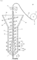
- FIG. 1 is a diagram schematically illustrating a 3D printer head for ejecting a multi-molding melt according to an exemplary embodiment of the present invention
- FIG. 2 is a diagram schematically illustrating a nozzle tip of the 3D printer head for ejecting the multi-molding melt according to the exemplary embodiment of the present invention
- FIG. 3 is a diagram illustrating a cross section of a molding melt ejected from the 3D printer head for ejecting the multi-molding melt according to the exemplary embodiment of the present invention.
- FIG. 4 is a diagram schematically illustrating a modified example of the nozzle tip of the 3D printer head for ejecting the multi-molding melt according to the exemplary embodiment of the present invention.
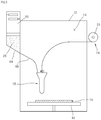
- FIG. 5 is a diagram schematically illustrating a 3D printer including a 3D printer head for ejecting a multi-molding melt according to another exemplary embodiment of the present invention
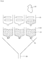
- FIG. 6 is a diagram for describing supplying a molding pellet of the 3D printer including the 3D printer head for ejecting the multi-molding melt according to another exemplary embodiment of the present invention.
- FIGS. 1 to 6 illustrate a printer body 12, an internal space 14, a stage 16, a 3D printer head 18, a 3D object 20, a molding filament 22, a filament supply unit 24, a filament supply reel 25, a molding pellet 26, an idler 27, a pellet supply unit 28, a conveying roll 29, a penetration portion 30, a nozzle pipe 32, a filament supply path 34, a rod body 34, a section enlarging portion 40, a spiral 38, a rotary screw 42, a nozzle tip 44, a nozzle hole 45, a heating unit 46, a first nozzle hole 47, a temperature sensor 48, a molding filament melt 49, a heating portion 50, a molding pellet melt 51, a molding melt 52, a second nozzle hole 53, a hopper portion 54, a mixing screw 56, a 3D waste 58, a crushing unit 60, a pellet storage portion 64, a pellet measuring unit 66, and a supply pipe 68.
- the 3D printer head 18 ejecting the multi-molding melt according to the exemplary embodiment is attached to a conveying mechanism (not illustrated) of the 3D printer to form a 3D object on a stage 16, the 3D printer will be first described with reference to FIGS. 5 and 6 , before the 3D printer head 18 according to the exemplary embodiment is described.
- the 3D printer head 18 ejecting the multi-molding melt includes a printer body 12 in which the internal space 14 is partitioned; a stage 16 dispose in the internal space 14 of the printer body 12; the 3D printer head 18 according to the exemplary embodiment disposed in the internal space 14 of the printer body 12 to eject a molding melt 52 on the stage; and a conveying mechanism (not illustrated) connected with the 3D printer head 18 to set a position of the 3D printer head.
- the printer body 12 forms a body of the 3D printer and may include a plurality of frames installed so as to partition the internal space 14, a transparent panel covering the frames, and the like.
- a conveying mechanism (not illustrated) moving 3-dimensionally the 3D printer head 18 to be described below may be provided, and the 3D printer head 18 is connected to the conveying mechanism.
- the stage 16 is disposed in the internal space 14 of the printer body 12.
- the stage 16 is a place where the molding melt 52 ejected from the 3D printer head 18 is stacked to form the 3D object 20, and may move 2-dimensionallyseparately from the conveying mechanism for moving the 3D printer head 18.
- the 3D printer head 18 is disposed in the internal space 14 of the printer body 12 and ejects the molding melt 52 on the stage 16 to form the 3D object 20.
- the 3D printer head 18 is disposed to face the stage 16 and forms the 3D object 20 while the molding melt 52 ejected from the 3D printer head 18 is stacked on the stage 16.
- the 3D printer head 18 ejects the multi- molding melt 52 by simultaneously supplying and melting the molding filament 22 and the molding pellets 26. This will be described below in detail.
- the pre-molded 3D object may be discarded to cause waste of an expensive molding source.
- the 3D printer head 18 may be configured to recycle the 3D waste 58 generated in the molding process. That is, as illustrated in FIG. 6 , the 3D waste 58 is finely crushed in the form of the molding pellets 26 to be used as a molding source, thereby reducing the waste of the material.
- the 3D printer head 18 ejecting the multi-molding melt according to the exemplary embodiment which ejects the multi-molding melt 52 by receiving the molding filament 22 and the molding pellets 26, includes a filament supply unit 24 supplying the molding filament 22; a pellet supply unit 28 supplying the molding pellets 26; a nozzle pipe 32 in which a penetration portion 30 is provided therein in a longitudinal direction, the molding pellets 26 are supplied from the pellet supply unit 28, and the molding pellets 26 move; a rotary screw 42 which is disposed in the penetration portion 30 of the nozzle pipe 32, advances the molding pellets 26 to one end of the nozzle pipe 32 by rotation; a heating portion 50 which melts the molding pellets 26 and the molding filament 22 by heating the nozzle pipe 32 to form the multi-molding melt 52; and a nozzle tip 44 which is connected to one end of the nozzle pipe 32 and ejects the molding melt 52.
- the molding filament 22 is a thin linear material made of thermoplastic, acrylonitrile butadiene styrene (ABS), polyacetic acid (PLA), etc., and a 3D printer material ejected while melted by heating after supplied to the 3D printer head 18 in the filament form.
- the molding filament 22 is wound on the filament supply reel 26 and then supplied to the 3D printer head 18 in the linear form according to the rotation of the conveying roll 29.
- the molding pellet 26 is a material melted by heat, such as thermoplastic, ABS, PLA, glass, and the like and provided in a granular form.
- the shape of the molding pellet 26 is shown in the granular form, but it is not limited thereto and includes powder-shaped molding pellets 26. Even in the molding filament 22, the molding pellets 26 in the raw material form are extruded and molded to form a wire-shaped molding filament 22.
- the multi-molding melt 52 mixed with different materials may be ejected by varying the material of the molding filament 22 and the material of the molding pellets 26. Accordingly, the multi-molding melt 52 is ejected to mold the 3D object 20.
- the multi-molding melt is formed of different molding materials to fabricate various types of 3D objects 20.
- the filament supply unit 24 may include the filament supply reel 25 wound with the molding filament 22 and the conveying roll 29 supplying the molding filament 22 wound on the filament supply reel 25 to the 3D printer head 18.
- the conveying roll 29 is rotated while the idler 27 is disposed on one outer periphery of the molding filament 22 and the conveying roll 29 is disposed on the other side, the molding filament 22 may be advanced or retreated by the frictional force between the conveying roll 29 and the molding filament 22.
- the pellet supply unit 28 stores the molding pellets 26 in a solid state and then supplies the molding pellets 26 to the nozzle pipe 32.
- the 3D object 20 is formed by melting only the molding filament 22 like the related art, a high-precise molding object may be fabricated by thinning the stacked layer.
- the molding efficiency may be deteriorated, and even in the large 3D object 20, the molding pellets 26 in the raw material form is used as a molding source together with the molding filament 22 to shorten the molding time.
- the pellet supply unit 29 includes a hopper portion 54 which communicates with the nozzle pipe 32 and supplies the molding pellets 26 to the nozzle pipe 32 and a mixing screw 56 which is provided in the hopper portion 54 and mixes the molding pellets 26 according to the rotation.
- a separate mixing screw spiral is attached to the rod body 34 of the rotary screw 42 so that the mixing screw 56 and the rotary screw 42 are simultaneously rotated.
- the mixing screw 56 and the rotary screw 42 may be separately rotated.
- the different molding pellets 26, which are measured by a pellet measuring unit 66 of each pellet storage portion 64 and introduced into the pellet supply unit 28, may be mixed with each other according to the rotation of the mixing screw 56 of the hopper portion 54 and then introduced into the nozzle pipe 32.
- the nozzle pipe 3 has a penetration portion 30 therein in a longitudinal direction and provides a path through which the molding pellets 26 are supplied from the pellet supply unit 28 and then move.
- the penetration portion 30 is formed by penetrating in the longitudinal direction of the nozzle pipe 32 and the solid-stated molding pellets 26 introduced from the pellet supply unit 28 move along the penetration portion 30.
- the rotary screw 42 is provided in the penetration portion 30 of the nozzle pipe 32 for movement of the molding pellets 26 and the molding pellets 26 of the penetration portion 30 are advance to one end or retreated to the other end according to the rotation of the rotary screw 42.
- the rotary screw 42 is disposed in the penetration portion 30 of the nozzle pipe 32 and the molding pellets 26 are advanced or retreated to the end of the nozzle pipe 32 according to the rotation.
- a filament supply path 34 through which the molding filament 22 is supplied is formed in the rotary screw 42 in the longitudinal direction.
- a driving unit such as a motor (not illustrated) is connected to the rotary screw 42 to advance or retreat the molding pellets 26 in the penetration portion 30 of the nozzle pipe 32 according to rotation and reverse rotation. Gaps of the threads of the rotary screw 42 may be determined by considering the size of the molding pellets 26, an ejecting speed of the molding melt 52, and the like.
- a filament supply path 34 through which the molding filament 22 to be described above is supplied is formed in the rotary screw 42.
- the molding filament 22 inserted at the other end of the rotary screw 42 moves to the one end of the rotary screw 42 through the filament supply path 34 and the molding filament 22 moving to one end is melted to be ejected to the nozzle tip 44.
- one filament supply path 34 is formed in the rod by 34 of the rotary screw 42 to supply one molding filament 22
- a plurality of different molding filaments 22 may be supplied by forming a plurality of filament supply paths 34 in the rod body 34.
- the molding pellets 26 move toward the one end of the rotary screw 42 by the rotation of the rotary screw 42, and simultaneously, the molding filament 22 is melted together by the heating portion 50 while moving toward one end of the rotary screw 42 through the filament supply path 34 of the rotary screw 42 to be ejected from the nozzle tip 44.
- the rotary screw 42 includes a linear rod body 34 formed through the filament supply path 34 in the longitudinal direction and a spiral 38 formed on the outer periphery of the linear rod body 34 in the longitudinal direction.
- the section enlarging portion 40 of which the cross section is enlarge toward one end of the rod body 34 is formed at one end of the rod body 34 and a height of the spiral 38 formed at the section enlarging portion 40 may be decreased toward one end of the rod body 34.
- the cross section of the molding pellet melt 51 which is ejected while the concrete mixture moves from one end to the other end of the nozzle pipe 32 is reduced to generate an ejection pressure, thereby ejecting a predetermined amount of molding pellet melt 51 ejected from the 3D printer head 18.
- the heating portion 50 melts the molding pellets 26 and the molding filament 22 by heating the nozzle pipe 32 to form the multi-molding melt 52. As described above, the molding pellets 26 and the molding filament 22 move toward one end of the nozzle pipe 32 through the rotary screw 42 and the heating portion 50 heats and melts the molding pellets 26 and the molding filament 22 in the moving process to form the multi-molding melt 52.
- the heating portion 50 includes a plurality of heating units 46 disposed to be spaced apart from each other in a longitudinal direction of the nozzle pipe 32.
- the heating unit 46 heats and melts the molding pellets 26 and the molding filament 22 in the solid state which move along the inside of the nozzle pipe 32.
- the heating units 46 may be spaced apart from each other in the longitudinal direction of the nozzle pipe 32, and in the exemplary embodiment, as illustrated in FIG. 1 , the heating units 46 are spaced apart from each other at one end of the nozzle pipe 32 adjacent to the nozzle tip 44.
- the molding pellets 26 and the molding filament 22 introduced through the other end of the nozzle pipe 32 are melted before being ejected from the nozzle tip 44 while moving to one end of the nozzle pipe 32 through the rotary screw 42.
- the molding pellets 26 may be uniformly melted while sequentially applying the heat by the plurality of heating units 46 spaced apart from each other.
- a temperature sensor 48 capable of measuring the temperature of the molding melt 52 at the position of each heating unit 46 is attached to each of the plurality of heating units 46 and a controller (not illustrated) measures the temperature of the molding melt 52 in each heating unit 46 to determine an optimum melting temperature.
- the 3D printer head 18 may include a head weight measuring unit (not illustrated) measuring the weight of the 3D printer head 18 described above.
- a head weight measuring unit (not illustrated) measuring the weight of the 3D printer head 18 described above.
- the molding pellets 26 in the solid state is phase-changed into the molding melt 52 in the liquid state by heating of the heating unit 46, the weight is physically changed, and a temperature of the molding melt 52 when a change in weight of the 3D printer head 18 occurs by measuring the weight of the 3D printer head 18 in addition to the temperature of the molding melt 52 in the heating unit 46 may be selected as the optimal melting temperature of the corresponding molding pellets 26.
- the optimum melting temperature of the corresponding molding pellets 26 may be known in advance by means of an experimental reports or the like, but in the case of recycling the 3D waste 58, the accurate melting temperature of the corresponding 3D waste 58 is often unknown. Accordingly, the accurate melting temperature of the corresponding 3D waste 58 may be determined by the plurality of heating units 46, the temperature sensor 48, and the head weight measuring unit (not illustrated) described above.
- the nozzle tip 44 is coupled to one end of the nozzle pipe 32 and ejects the molding filament melt 49 and the molding pellet melt 51 during the movement of the nozzle pipe 32.
- FIG. 2 illustrates the nozzle tip 44 according to the exemplary embodiment and a nozzle hole 45 through which the molding melt 52 is ejected is provided in the nozzle tip 44.
- the molding filament melt 49 ejected through the filament supply path 34 of the rotary screw 42 is ejected from the center of the nozzle hole 45 and the molding pellet melt 51 is ejected through the nozzle hole 45 while covering the molding filament melt 49 at the core. That is, referring to FIGS.
- the molding filament melt 49 is ejected through the center of the rotary screw 42 and the molding pellet melt 51 is ejected while covering the molding filament melt 49 by moving along the outer periphery of the rotary screw 42. Accordingly, as illustrated in FIG. 3 , the molding filament melt 49 is positioned at the core of the molding pellet melt 51 and has the same cross section even after curing.
- the molding filament 22 and the molding pellets 26 are selected so that the rigidity after curing the molding filament melt 49 is greater than the rigidity after curing the molding pellet melt 51.
- the 3D object 20 is made of a material having large rigidity, the cost may increase due to the characteristic of the material, and as a result, the material of the core forming a skeleton is selected as a material having large rigidity and an outer periphery material covering the core is selected as a material having slightly weak rigidity to form the 3D object 20, thereby obtaining a cost reduction effect.
- a plurality of nozzle tips 44 may be provided and each of the plurality of nozzle tips 44 may be interchangeably coupled to one end of the nozzle pipe 32, and in each of the plurality of nozzle tips 44, nozzle holes 45 having different ejection patterns may be formed.
- nozzle tips 44 having nozzle holes 45 having different ejection patterns are prepared and the nozzle tip 44 may be replaced according to the shape and characteristics of the 3D object 20.
- FIG. 4 illustrates various types of nozzle holes 45 including a first nozzle hole 47 through which the molding filament melt 49 is ejected and a second nozzle hole 53 which is formed along the outer periphery of the first nozzle hole 47 and through which the molding pellet melt 51 is ejected.
- the first nozzle hole 47 is formed at a position corresponding to the filament supply path 34 of the rotary screw 42 to eject the molding filament melt 49 and the second nozzle hole 49 is formed at a position corresponding to the outer periphery of the rotary screw 42 to eject the molding pellet melt 51 while covering the molding filament melt 49.
- the nozzle pipe 32 may be made of a metallic material having high thermal conductivity, for example, a material including brass, aluminum, and the like.
- a heating portion 50 for melting the molding filament 22 and the molding pellets 26 in the nozzle pipe 32 is provided outside the nozzle pipe 32, and the heat of the heating portion 50 is made of a material having high thermal conductivity so that the heat of the heating portion 50 is easily transmitted to the molding pellets 26 and the molding filament 22.
- FIG. 6 is a diagram for describing a process of supplying the molding pellets of the 3D printer according to the exemplary embodiment.
- the 3D printer according to the exemplary embodiment includes a plurality of pellet storage portions 64 storing a plurality of different molding pellets 26 and supplying the plurality of molding pellets 26 to the pellet supply portion 28; and a pellet measuring unit 66 connected to each of the plurality of pellet storage portions 64 to measure the molding pellets 26 supplied from the each pellet storage portion 64 to the pellet supply portion 28.
- a molding melt 52 having a new characteristic may be fabricate by mixing a plurality of molding pellets 26 having different characteristics.
- the molding melt 52 having a desired color is formed by mixing the molding pellets 26 having different colors at an appropriate mixing ratio to form a 3D object 20 having various colors.
- the pellet measuring portion 66 capable of adjusting a mixing amount of the molding pellets 26 is provided with each pellet storage unit 64 to determine a mixing amount of the plurality of molding pellets 26 according to a desired characteristic of the user. Accordingly, the molding pellets 26 are measured in the pellet measuring portion 66 of each pellet storage portion 64 and mixed to be supplied to the pellet supply portion 28 through the supply pipe 68.
- the different molding pellets 26, which are measured by the pellet measuring portion 66 of each pellet storage portion 64 and introduced into the pellet supply unit 28, may be mixed with each other according to the rotation of the mixing screw 56 of the hopper portion 54 to be introduced into the nozzle pipe 32.
- the molding pellets 26 to be mixed with each other are melted by the plurality of heating units 46 of the nozzle pipe 32, resulting in a phase change to the molding pellet melt 51.
- the optimum melting temperature is determined through the plurality of heating units 46 and heated to the optimal melting temperature to form a homogeneous molding pellet melt 51.
- the 3D printer may recycle the 3D waste 58.
- the pre-molded 3D object 20 may be discarded to cause waste of an expensive molding source.
- the 3D waste 58 is finely crushed and supplied to the 3D printer head 18 to be recycled.
- the crushing unit 60 finely crushes the introduced 3D waste 58 and the crushed 3D waste is regenerated in the form of molding pellets 26 and supplied to the pellet storage portion 64.
- the regenerated molding pellets 26 supplied to the pellet storage portion 64 are again supplied to the 3D printer head 18 and used as a molding source.
- the crushing unit 60 sequentially crushes the large bulk by configuring the crushing process into a plurality of stages and crushes the molding source into the usable pellet forms to supply the pellet in the pellet storage portion 64.
Landscapes
- Engineering & Computer Science (AREA)
- Chemical & Material Sciences (AREA)
- Materials Engineering (AREA)
- Manufacturing & Machinery (AREA)
- Mechanical Engineering (AREA)
- Physics & Mathematics (AREA)
- Optics & Photonics (AREA)
- Thermal Sciences (AREA)
- Ceramic Engineering (AREA)
- Civil Engineering (AREA)
- Composite Materials (AREA)
- Structural Engineering (AREA)
Claims (11)
- 3D-Druckkopf (18) zum Ausstoßen einer Multiformschmelze (52), wobei der Druckkopf (18) daran angepasst ist, ein Formfilament (22) und Formpellets (26) aufzunehmen, wobei der 3D-Druckkopf (18) umfasst:eine Filamentzuführeinheit (24), die das Formfilament (22) zuführt;eine Pelletzuführeinheit (28), die die Formpellets (26) zuführt;ein Düsenrohr (32), in dem ein Durchdringungsabschnitt (30) darin in einer Längsrichtung vorgesehen ist, wobei die Formpellets (26) von der Pelletzuführeinheit (28) zugeführt werden, und sich die Formpellets bewegen;eine rotierende Schnecke (42), die in dem Durchdringungsabschnitt (30) des Düsenrohrs (32) angeordnet ist, wobei die rotierende Schnecke (42) daran angepasst ist, die Formpellets (26) durch Rotation zu einem Ende des Düsenrohrs (32) voranzubringen, und einen Filamentzuführpfad (34) aufweist, durch welchen das Formfilament (22) zugeführt wird, wobei der Filamentzuführpfad in der rotierenden Schnecke (42) in einer Längsrichtung gebildet ist;einen Erwärmungsabschnitt (50), der daran angepasst ist, durch Erwärmen des Düsenrohrs (32) die Formpellets (26) und das Formfilament (22) zu schmelzen, wodurch die Multiformschmelze (52) gebildet wird; undeine Düsenspitze (44), die mit einem Ende des Düsenrohrs (32) verbunden ist und daran angepasst ist, die Multiformschmelze (52) auszustoßen,wobei der Erwärmungsabschnitt (50) eine Vielzahl von Erwärmungseinheiten (46) umfasst, die in einer Längsrichtung des Düsenrohrs (32) voneinander beabstandet angeordnet sind, undwobei der 3D-Druckkopf (18) ferner eine Kopfgewichtsmesseinheit umfasst, die daran angepasst ist, das Gewicht des 3D-Druckkopfs (18) zu messen.
- 3D-Druckkopf (18) nach Anspruch 1, wobei die Pelletzuführeinheit (28)einen Trichterabschnitt (54), der mit dem Düsenrohr (32) in Verbindung steht und daran angepasst ist, dem Düsenrohr (32) die Formpellets (26) zuzuführen; undeine Mischschnecke (56) umfasst, die in dem Trichterabschnitt (54) vorgesehen ist und daran angepasst ist, die Formpellets (26) gemäß der Rotation zu mischen.
- 3D-Druckkopf (18) nach Anspruch 1, wobei die rotierende Schnecke (42)einen linearen Stangenkörper (34), der durch den Filamentzuführpfad (34) in der Längsrichtung gebildet ist; undeine Spirale (38) umfasst, die auf dem Außenumfang des linearen Stangenkörpers (34) in der Längsrichtung gebildet ist,wobei ein Schnitterweiterungsabschnitt (40), dessen Querschnitt zu einem Ende des Stangenkörpers (34) hin erweitert ist, an einem Ende des Stangenkörpers (34) gebildet ist und eine Höhe der Spirale (38), die an dem Schnitterweiterungsabschnitt (40) gebildet ist, zu einem Ende des Stangenkörpers (34) hin verringert ist.
- 3D-Druckkopf (18) nach Anspruch 1, wobei Düsenlöcher (45), durch welche die Multiformschmelze (52) ausgestoßen wird, in der Düsenspitze (44) vorgesehen sind, und
wobei die Düsenlöcher (45)ein erstes Düsenloch (47), durch welches die Formfilamentschmelze (49) ausgestoßen wird; undein zweites Düsenloch (53) umfassen, welches entlang des Außenumfangs des ersten Düsenlochs (47) gebildet ist und durch welches die Formpelletschmelze (51) ausgestoßen wird. - 3D-Druckkopf (18) nach Anspruch 1, wobei eine Vielzahl von Düsenspitzen (44) vorgesehen ist und jede der Vielzahl von Düsenspitzen (44) austauschbar mit einem Ende des Düsenrohrs (32) gekoppelt ist, und in jedem der Vielzahl von Düsenspitzen (44) Düsenlöcher gebildet sind, die unterschiedliche Ausstoßmuster aufweisen.
- 3D-Druckkopf (18) nach Anspruch 1, wobei an einem Ende des Düsenrohrs (32) angrenzend an die Düsenspitze (44) die Vielzahl von Erwärmungseinheiten (46) voneinander beabstandet sind.
- 3D-Druckkopf (18) nach Anspruch 1, wobei ein Temperatursensor (48), der daran angepasst ist, die Temperatur der Formschmelze (52) zu messen, in jeder der Vielzahl von Erwärmungseinheiten (46) vorgesehen ist.
- 3D-Druckkopf (18) nach Anspruch 1, wobei das Düsenrohr (32) aus einem metallischen Material besteht, das eine hohe thermische Leitfähigkeit aufweist.
- 3D-Drucker zum Ausstoßen einer Multiformschmelze (52), umfassend:einen Druckerkörper (12), in dem ein Innenraum (14) abgeteilt ist;ein Gestell (16), das in dem Innenraum (14) des Druckerkörpers (12) angeordnet ist;den 3D-Druckkopf (18) nach einem der Ansprüche 1 bis 8, der in dem Innenraum (14) des Druckerkörpers (12) angeordnet ist, um eine Formschmelze (52) auf dem Gestell (16) auszustoßen; undeinen Fördermechanismus, der mit dem 3D-Druckkopf (18) verbunden ist, um eine Position des 3D-Druckkopfs (18) einzustellen.
- 3D-Drucker nach Anspruch 9, ferner umfassend:eine Vielzahl von Pelletspeicherabschnitten (64), die daran angepasst sind, eine Vielzahl von unterschiedlichen Formpellets (26) zu speichern und dem Pelletzuführabschnitt (28) die Vielzahl von Formpellets (26) zuzuführen; undeine Pelletmesseinheit (66), die mit jedem der Vielzahl von Pelletspeicherabschnitten (64) verbunden und daran angepasst ist, die von jedem der Pelletspeicherabschnitte (64) dem Pelletzuführabschnitt (28) zugeführten Formpellets (26) zu messen.
- 3D-Drucker nach Anspruch 10, ferner umfassend:
eine Zerkleinerungseinheit (60), die daran angepasst ist, 3D-Abfall fein zu zerkleinern, um Formpellets zu regenerieren, und die regenerierten Formpellets der Vielzahl von Pelletspeicherabschnitten (64) zuzuführen.
Applications Claiming Priority (2)
| Application Number | Priority Date | Filing Date | Title |
|---|---|---|---|
| KR1020160058334A KR101807794B1 (ko) | 2016-05-12 | 2016-05-12 | 다중 조형 용융액을 토출하는 3차원 프린터 헤드 및 이를 포함하는 3차원 프린터 |
| PCT/KR2016/011334 WO2017195947A1 (ko) | 2016-05-12 | 2016-10-11 | 다중 조형 용융액을 토출하는 3차원 프린터 헤드 및 이를 포함하는 3차원 프린터 |
Publications (3)
| Publication Number | Publication Date |
|---|---|
| EP3299151A1 EP3299151A1 (de) | 2018-03-28 |
| EP3299151A4 EP3299151A4 (de) | 2019-01-09 |
| EP3299151B1 true EP3299151B1 (de) | 2020-02-26 |
Family
ID=60266549
Family Applications (1)
| Application Number | Title | Priority Date | Filing Date |
|---|---|---|---|
| EP16901165.7A Active EP3299151B1 (de) | 2016-05-12 | 2016-10-11 | Kopf für einen dreidimensionalen drucker zur ausgabe mehrerer formschmelzlösungen und dreidimensionaler drucker damit |
Country Status (4)
| Country | Link |
|---|---|
| US (1) | US20180126636A1 (de) |
| EP (1) | EP3299151B1 (de) |
| KR (1) | KR101807794B1 (de) |
| WO (1) | WO2017195947A1 (de) |
Families Citing this family (34)
| Publication number | Priority date | Publication date | Assignee | Title |
|---|---|---|---|---|
| US10287218B2 (en) * | 2016-08-09 | 2019-05-14 | Raytheon Company | Solid propellant additive manufacturing method and system |
| US20180224050A1 (en) * | 2017-02-03 | 2018-08-09 | Oleg Tumarkin | Deposition device for well construction |
| PL3600811T3 (pl) * | 2017-08-09 | 2023-08-14 | Sika Technology Ag | Sposób nakładania kompozycji spoiwa mineralnego zawierających włókna |
| US11167486B2 (en) * | 2017-08-29 | 2021-11-09 | Magzero Llc | Three dimensional printer system |
| KR102039491B1 (ko) * | 2017-11-28 | 2019-11-04 | 주식회사 인스턴 | 미용융을 방지한 모듈형 스마트노즐 |
| KR102020359B1 (ko) * | 2017-11-28 | 2019-09-11 | 주식회사 인스턴 | 모듈형 압력 제어 스마트노즐 |
| DE102018100051A1 (de) * | 2018-01-03 | 2019-07-04 | Gabriele Schramm | Verfahren zur Verarbeitung von thermoplastischem Material |
| CN108582760B (zh) * | 2018-05-17 | 2023-06-13 | 东莞职业技术学院 | 一种基于文创产品的纸基3d打印设备 |
| NL2021152B1 (en) * | 2018-06-19 | 2020-01-06 | Cead B V | Device and method for continuous extrusion-based fiber additive manufacturing |
| DE102018118883B3 (de) | 2018-08-03 | 2020-01-16 | Kraussmaffei Technologies Gmbh | Verfahren und Vorrichtung zur Herstellung eines faserverstärkten Plastifikats und Verwendung der Vorrichtung zur additiven Fertigung |
| KR102098192B1 (ko) * | 2018-09-13 | 2020-04-07 | 인하대학교 산학협력단 | 3d 프린터 이종 재료 출력을 위한 노즐 배합 시스템 구조 및 방법 |
| CN109228340A (zh) * | 2018-10-29 | 2019-01-18 | 共享智能铸造产业创新中心有限公司 | 一种应用于fdm打印机的打印头 |
| DE102018130273A1 (de) * | 2018-11-29 | 2020-06-04 | Homag Gmbh | Düse sowie Verfahren zum additiven Ausbilden eines Abschnitts |
| CN109968659A (zh) * | 2019-04-09 | 2019-07-05 | 天津大学 | 一种变深等距螺杆式生物3d打印挤出装置 |
| CN110341162A (zh) * | 2019-07-26 | 2019-10-18 | 金贵建 | 一种新型挤塑模具 |
| US12415229B2 (en) | 2020-07-29 | 2025-09-16 | Blue Origin Manufacturing, LLC | Friction stir welding systems and methods |
| WO2022023603A1 (es) * | 2020-07-29 | 2022-02-03 | Fundacion Tekniker | Cabezal de impresión de fabricación aditiva en plástico y métodos |
| CN112497740A (zh) * | 2020-10-27 | 2021-03-16 | 南京航空航天大学 | 一种光固化-fdm组合材料打印机喷头及其工作方法 |
| KR102290995B1 (ko) * | 2020-11-20 | 2021-08-19 | (주)화암인더스트리 | 폐 플라스틱을 활용한 리사이클링 3d프린터 |
| KR102422177B1 (ko) * | 2021-02-23 | 2022-07-21 | 한국과학기술원 | 동축 섬유 압출 노즐 및 이를 이용한 다중 소재 3d 프린터 |
| WO2022232022A1 (en) * | 2021-04-27 | 2022-11-03 | Essentium Ipco, Llc | Rotatable receiver for a three-dimensional printer head |
| KR20230012195A (ko) * | 2021-07-15 | 2023-01-26 | 현대자동차주식회사 | 3d 프린팅 장치 및 방법 |
| CN113442431A (zh) * | 2021-07-29 | 2021-09-28 | 安徽国防科技职业学院 | 一种3d打印机的混色打印方法 |
| US12583181B2 (en) | 2021-08-27 | 2026-03-24 | Kyoraku Co., Ltd. | Thermal melting three-dimensional printer and method for producing molded object |
| KR102895936B1 (ko) | 2022-04-26 | 2025-12-05 | 한국원자력연구원 | 복합 구조체 제조장치 및 방법 |
| KR102827385B1 (ko) * | 2022-05-02 | 2025-07-01 | 충북대학교 산학협력단 | 3d 프린터용 복합체 전도성 필라멘트 제조 장치 |
| EP4572943A1 (de) | 2022-08-18 | 2025-06-25 | Signify Holding B.V. | Einzeldüsen-pelletextruder mit seitenseitiger fdm-filamentzuführung |
| US12140109B2 (en) | 2023-03-30 | 2024-11-12 | Blue Origin, Llc | Transpiration-cooled systems having permeable and non-permeable portions |
| US12246392B2 (en) | 2023-03-30 | 2025-03-11 | Blue Origin Manufacturing, LLC | Deposition head for friction stir additive manufacturing devices and methods |
| US12172229B2 (en) | 2023-03-30 | 2024-12-24 | Blue Origin, Llc | Friction stir additive manufacturing devices and methods for forming in-situ rivets |
| IT202300010281A1 (it) * | 2023-05-22 | 2024-11-22 | Csp S R L | Apparecchiatura e metodo per stampa tridimensionale di materiale termoplastico muticolore e/o multimateriale |
| US12303994B2 (en) | 2023-08-03 | 2025-05-20 | Blue Origin Manufacturing, LLC | Friction stir additive manufacturing formed parts and structures with integrated passages |
| US12383975B2 (en) | 2023-08-03 | 2025-08-12 | Blue Origin Manufacturing, LLC | Friction stir additive manufacturing formed parts and structures with integrated passages |
| US12589446B2 (en) | 2023-12-12 | 2026-03-31 | Blue Origin Manufacturing, LLC | Wire-feed friction stir additive manufacturing systems, devices, and methods |
Family Cites Families (15)
| Publication number | Priority date | Publication date | Assignee | Title |
|---|---|---|---|---|
| US4955550A (en) * | 1987-11-07 | 1990-09-11 | Toyota Jidosha Kabushiki Kaisha | Quantitative feeding apparatus usable for pulverized and/or granular material and batch type multi-colored automatic feeding apparatus |
| US5764521A (en) * | 1995-11-13 | 1998-06-09 | Stratasys Inc. | Method and apparatus for solid prototyping |
| DE10062590B4 (de) * | 2000-12-15 | 2005-12-29 | Fränkische Rohrwerke Gebr. Kirchner GmbH + Co. KG | Düsenanordnung zur Coextrusion |
| KR100483945B1 (ko) * | 2002-05-16 | 2005-04-20 | 주식회사 신광엔지니어링 | 폐수지 재생용 압출 성형장치 |
| JP2013215919A (ja) * | 2012-04-05 | 2013-10-24 | Kojima Sangyo Kk | 樹脂材再生方法 |
| IL229012A (en) * | 2013-10-21 | 2016-06-30 | Micron 3Dp Ltd | Detachable fiber carrier and nozzle for a 3D printer |
| KR101610897B1 (ko) * | 2014-04-02 | 2016-04-08 | (주) 허브인소프트 | 다양한 색상이 구현되는 3차원 프린터 |
| KR20150126120A (ko) * | 2014-05-02 | 2015-11-11 | 주식회사 스카이블루텍 | 3 d 프린터용 재료공급장치 및 재료공급방법 |
| US20150321419A1 (en) * | 2014-05-06 | 2015-11-12 | Todd Linthicum | Extrusion system for additive manufacturing and 3-d printing |
| KR101769144B1 (ko) * | 2014-05-22 | 2017-08-18 | 바이오메디칼쓰리디프린팅 주식회사 | Fdm용 필라멘트 제조 장치,와이어가 담지된 fdm용 필라멘트 및 이를 이용하는 3차원 프린터 |
| JP6184916B2 (ja) * | 2014-07-31 | 2017-08-23 | 富士フイルム株式会社 | 放射線画像撮影システム |
| KR20160030616A (ko) * | 2014-09-11 | 2016-03-21 | 김진규 | 펠티어소자를 이용한 3d 프린터용 노즐 및 헤드 |
| CN204160774U (zh) * | 2014-09-15 | 2015-02-18 | 余金文 | 一种熔融堆积3d打印机 |
| KR101662501B1 (ko) * | 2014-09-23 | 2016-10-06 | 주식회사 케이씨티 | 3차원 프린터 |
| KR101582609B1 (ko) * | 2015-06-12 | 2016-01-05 | 주식회사 리뉴캔 | 3d 프린터 재료 재활용 장치 |
-
2016
- 2016-05-12 KR KR1020160058334A patent/KR101807794B1/ko active Active
- 2016-10-11 US US15/574,522 patent/US20180126636A1/en not_active Abandoned
- 2016-10-11 EP EP16901165.7A patent/EP3299151B1/de active Active
- 2016-10-11 WO PCT/KR2016/011334 patent/WO2017195947A1/ko not_active Ceased
Non-Patent Citations (1)
| Title |
|---|
| None * |
Also Published As
| Publication number | Publication date |
|---|---|
| KR101807794B1 (ko) | 2017-12-08 |
| EP3299151A4 (de) | 2019-01-09 |
| US20180126636A1 (en) | 2018-05-10 |
| EP3299151A1 (de) | 2018-03-28 |
| KR20170127782A (ko) | 2017-11-22 |
| WO2017195947A1 (ko) | 2017-11-16 |
Similar Documents
| Publication | Publication Date | Title |
|---|---|---|
| EP3299151B1 (de) | Kopf für einen dreidimensionalen drucker zur ausgabe mehrerer formschmelzlösungen und dreidimensionaler drucker damit | |
| US10836090B2 (en) | Three-dimensional fabrication with cavity filling | |
| US10456968B2 (en) | Three-dimensional object printer with multi-nozzle extruders and dispensers for multi-nozzle extruders and printheads | |
| US10625466B2 (en) | Extrusion printheads for three-dimensional object printers | |
| US10335991B2 (en) | System and method for operation of multi-nozzle extrusion printheads in three-dimensional object printers | |
| KR101523692B1 (ko) | 3차원 프린터 | |
| KR101524441B1 (ko) | 다수의 원료공급부가 형성된 3d 프린터의 헤드 | |
| JP5913062B2 (ja) | 射出成形機、射出成形システム、および原料計量装置 | |
| KR20150126120A (ko) | 3 d 프린터용 재료공급장치 및 재료공급방법 | |
| KR101887928B1 (ko) | 3차원 프린터 헤드, 3차원 프린터 및 3차원 프린팅 펜 | |
| KR102088676B1 (ko) | 3d 프린팅 시스템 및 이의 구동 방법 | |
| KR20170122557A (ko) | 고체 조형 펠릿을 이용하는 3차원 프린터 | |
| JP5846998B2 (ja) | 可塑化装置、射出装置、射出成形装置、押出機、及び成形品の製造方法 | |
| CN101896327A (zh) | 注射装置 | |
| KR20160039176A (ko) | 3 d 프린터용 재료공급장치 및 재료공급방법 | |
| CN106671411A (zh) | 一种能够将短切纤维和热塑性树脂复合的快速成型方法 | |
| JP2020044845A (ja) | 成形機および部品成形方法 | |
| EP4100228A1 (de) | Niederdruckgiessanlage | |
| JP2021075019A (ja) | 造形装置および造形方法 | |
| KR20220082038A (ko) | 대리석 무늬 성형 부품의 제조 방법 및 장치, 및 이 장치의 제조 방법 | |
| WO2012037402A2 (en) | System and method for rapid fabrication of arbitrary three-dimensional objects | |
| JP5941727B2 (ja) | スクリュ、可塑化装置、射出装置、射出成形装置、押出機、及び成形品の製造方法 | |
| JP6118619B2 (ja) | 可塑化装置、成形装置、可塑化方法、及び成形品の製造方法 | |
| JP2020168802A (ja) | 可塑化装置の材料供給方法および可塑化装置の材料供給装置 | |
| WO2020131013A1 (en) | Breakable three dimensional (3d) printed molds |
Legal Events
| Date | Code | Title | Description |
|---|---|---|---|
| STAA | Information on the status of an ep patent application or granted ep patent |
Free format text: STATUS: THE INTERNATIONAL PUBLICATION HAS BEEN MADE |
|
| PUAI | Public reference made under article 153(3) epc to a published international application that has entered the european phase |
Free format text: ORIGINAL CODE: 0009012 |
|
| STAA | Information on the status of an ep patent application or granted ep patent |
Free format text: STATUS: REQUEST FOR EXAMINATION WAS MADE |
|
| 17P | Request for examination filed |
Effective date: 20171222 |
|
| AK | Designated contracting states |
Kind code of ref document: A1 Designated state(s): AL AT BE BG CH CY CZ DE DK EE ES FI FR GB GR HR HU IE IS IT LI LT LU LV MC MK MT NL NO PL PT RO RS SE SI SK SM TR |
|
| AX | Request for extension of the european patent |
Extension state: BA ME |
|
| RIC1 | Information provided on ipc code assigned before grant |
Ipc: B33Y 30/00 20150101ALI20181128BHEP Ipc: B29C 64/209 20170101ALI20181128BHEP Ipc: B29C 47/04 20060101ALI20181128BHEP Ipc: B29C 64/336 20170101ALI20181128BHEP Ipc: B29C 64/118 20170101AFI20181128BHEP Ipc: B29C 47/10 20060101ALI20181128BHEP |
|
| A4 | Supplementary search report drawn up and despatched |
Effective date: 20181206 |
|
| DAV | Request for validation of the european patent (deleted) | ||
| DAX | Request for extension of the european patent (deleted) | ||
| REG | Reference to a national code |
Ref country code: DE Ref legal event code: R079 Ref document number: 602016030851 Country of ref document: DE Free format text: PREVIOUS MAIN CLASS: B29C0067000000 Ipc: B29C0064118000 |
|
| GRAP | Despatch of communication of intention to grant a patent |
Free format text: ORIGINAL CODE: EPIDOSNIGR1 |
|
| STAA | Information on the status of an ep patent application or granted ep patent |
Free format text: STATUS: GRANT OF PATENT IS INTENDED |
|
| RIC1 | Information provided on ipc code assigned before grant |
Ipc: B29C 64/209 20170101ALI20191001BHEP Ipc: B29C 64/336 20170101ALI20191001BHEP Ipc: B29C 64/295 20170101ALI20191001BHEP Ipc: B29C 48/80 20190101ALI20191001BHEP Ipc: B29C 64/118 20170101AFI20191001BHEP Ipc: B33Y 30/00 20150101ALI20191001BHEP Ipc: B29C 48/345 20190101ALI20191001BHEP Ipc: B29C 48/30 20190101ALI20191001BHEP Ipc: B29C 48/285 20190101ALI20191001BHEP |
|
| INTG | Intention to grant announced |
Effective date: 20191022 |
|
| GRAS | Grant fee paid |
Free format text: ORIGINAL CODE: EPIDOSNIGR3 |
|
| GRAA | (expected) grant |
Free format text: ORIGINAL CODE: 0009210 |
|
| STAA | Information on the status of an ep patent application or granted ep patent |
Free format text: STATUS: THE PATENT HAS BEEN GRANTED |
|
| AK | Designated contracting states |
Kind code of ref document: B1 Designated state(s): AL AT BE BG CH CY CZ DE DK EE ES FI FR GB GR HR HU IE IS IT LI LT LU LV MC MK MT NL NO PL PT RO RS SE SI SK SM TR |
|
| REG | Reference to a national code |
Ref country code: GB Ref legal event code: FG4D |
|
| REG | Reference to a national code |
Ref country code: CH Ref legal event code: EP |
|
| REG | Reference to a national code |
Ref country code: DE Ref legal event code: R096 Ref document number: 602016030851 Country of ref document: DE |
|
| REG | Reference to a national code |
Ref country code: AT Ref legal event code: REF Ref document number: 1237098 Country of ref document: AT Kind code of ref document: T Effective date: 20200315 |
|
| REG | Reference to a national code |
Ref country code: IE Ref legal event code: FG4D |
|
| PG25 | Lapsed in a contracting state [announced via postgrant information from national office to epo] |
Ref country code: RS Free format text: LAPSE BECAUSE OF FAILURE TO SUBMIT A TRANSLATION OF THE DESCRIPTION OR TO PAY THE FEE WITHIN THE PRESCRIBED TIME-LIMIT Effective date: 20200226 Ref country code: FI Free format text: LAPSE BECAUSE OF FAILURE TO SUBMIT A TRANSLATION OF THE DESCRIPTION OR TO PAY THE FEE WITHIN THE PRESCRIBED TIME-LIMIT Effective date: 20200226 Ref country code: NO Free format text: LAPSE BECAUSE OF FAILURE TO SUBMIT A TRANSLATION OF THE DESCRIPTION OR TO PAY THE FEE WITHIN THE PRESCRIBED TIME-LIMIT Effective date: 20200526 |
|
| REG | Reference to a national code |
Ref country code: NL Ref legal event code: MP Effective date: 20200226 |
|
| REG | Reference to a national code |
Ref country code: LT Ref legal event code: MG4D |
|
| PG25 | Lapsed in a contracting state [announced via postgrant information from national office to epo] |
Ref country code: SE Free format text: LAPSE BECAUSE OF FAILURE TO SUBMIT A TRANSLATION OF THE DESCRIPTION OR TO PAY THE FEE WITHIN THE PRESCRIBED TIME-LIMIT Effective date: 20200226 Ref country code: HR Free format text: LAPSE BECAUSE OF FAILURE TO SUBMIT A TRANSLATION OF THE DESCRIPTION OR TO PAY THE FEE WITHIN THE PRESCRIBED TIME-LIMIT Effective date: 20200226 Ref country code: IS Free format text: LAPSE BECAUSE OF FAILURE TO SUBMIT A TRANSLATION OF THE DESCRIPTION OR TO PAY THE FEE WITHIN THE PRESCRIBED TIME-LIMIT Effective date: 20200626 Ref country code: BG Free format text: LAPSE BECAUSE OF FAILURE TO SUBMIT A TRANSLATION OF THE DESCRIPTION OR TO PAY THE FEE WITHIN THE PRESCRIBED TIME-LIMIT Effective date: 20200526 Ref country code: GR Free format text: LAPSE BECAUSE OF FAILURE TO SUBMIT A TRANSLATION OF THE DESCRIPTION OR TO PAY THE FEE WITHIN THE PRESCRIBED TIME-LIMIT Effective date: 20200527 Ref country code: LV Free format text: LAPSE BECAUSE OF FAILURE TO SUBMIT A TRANSLATION OF THE DESCRIPTION OR TO PAY THE FEE WITHIN THE PRESCRIBED TIME-LIMIT Effective date: 20200226 |
|
| PG25 | Lapsed in a contracting state [announced via postgrant information from national office to epo] |
Ref country code: NL Free format text: LAPSE BECAUSE OF FAILURE TO SUBMIT A TRANSLATION OF THE DESCRIPTION OR TO PAY THE FEE WITHIN THE PRESCRIBED TIME-LIMIT Effective date: 20200226 |
|
| PG25 | Lapsed in a contracting state [announced via postgrant information from national office to epo] |
Ref country code: RO Free format text: LAPSE BECAUSE OF FAILURE TO SUBMIT A TRANSLATION OF THE DESCRIPTION OR TO PAY THE FEE WITHIN THE PRESCRIBED TIME-LIMIT Effective date: 20200226 Ref country code: CZ Free format text: LAPSE BECAUSE OF FAILURE TO SUBMIT A TRANSLATION OF THE DESCRIPTION OR TO PAY THE FEE WITHIN THE PRESCRIBED TIME-LIMIT Effective date: 20200226 Ref country code: SK Free format text: LAPSE BECAUSE OF FAILURE TO SUBMIT A TRANSLATION OF THE DESCRIPTION OR TO PAY THE FEE WITHIN THE PRESCRIBED TIME-LIMIT Effective date: 20200226 Ref country code: EE Free format text: LAPSE BECAUSE OF FAILURE TO SUBMIT A TRANSLATION OF THE DESCRIPTION OR TO PAY THE FEE WITHIN THE PRESCRIBED TIME-LIMIT Effective date: 20200226 Ref country code: SM Free format text: LAPSE BECAUSE OF FAILURE TO SUBMIT A TRANSLATION OF THE DESCRIPTION OR TO PAY THE FEE WITHIN THE PRESCRIBED TIME-LIMIT Effective date: 20200226 Ref country code: DK Free format text: LAPSE BECAUSE OF FAILURE TO SUBMIT A TRANSLATION OF THE DESCRIPTION OR TO PAY THE FEE WITHIN THE PRESCRIBED TIME-LIMIT Effective date: 20200226 Ref country code: PT Free format text: LAPSE BECAUSE OF FAILURE TO SUBMIT A TRANSLATION OF THE DESCRIPTION OR TO PAY THE FEE WITHIN THE PRESCRIBED TIME-LIMIT Effective date: 20200719 Ref country code: LT Free format text: LAPSE BECAUSE OF FAILURE TO SUBMIT A TRANSLATION OF THE DESCRIPTION OR TO PAY THE FEE WITHIN THE PRESCRIBED TIME-LIMIT Effective date: 20200226 Ref country code: ES Free format text: LAPSE BECAUSE OF FAILURE TO SUBMIT A TRANSLATION OF THE DESCRIPTION OR TO PAY THE FEE WITHIN THE PRESCRIBED TIME-LIMIT Effective date: 20200226 |
|
| REG | Reference to a national code |
Ref country code: AT Ref legal event code: MK05 Ref document number: 1237098 Country of ref document: AT Kind code of ref document: T Effective date: 20200226 |
|
| REG | Reference to a national code |
Ref country code: DE Ref legal event code: R097 Ref document number: 602016030851 Country of ref document: DE |
|
| PLBE | No opposition filed within time limit |
Free format text: ORIGINAL CODE: 0009261 |
|
| STAA | Information on the status of an ep patent application or granted ep patent |
Free format text: STATUS: NO OPPOSITION FILED WITHIN TIME LIMIT |
|
| PG25 | Lapsed in a contracting state [announced via postgrant information from national office to epo] |
Ref country code: AT Free format text: LAPSE BECAUSE OF FAILURE TO SUBMIT A TRANSLATION OF THE DESCRIPTION OR TO PAY THE FEE WITHIN THE PRESCRIBED TIME-LIMIT Effective date: 20200226 Ref country code: IT Free format text: LAPSE BECAUSE OF FAILURE TO SUBMIT A TRANSLATION OF THE DESCRIPTION OR TO PAY THE FEE WITHIN THE PRESCRIBED TIME-LIMIT Effective date: 20200226 |
|
| 26N | No opposition filed |
Effective date: 20201127 |
|
| PG25 | Lapsed in a contracting state [announced via postgrant information from national office to epo] |
Ref country code: PL Free format text: LAPSE BECAUSE OF FAILURE TO SUBMIT A TRANSLATION OF THE DESCRIPTION OR TO PAY THE FEE WITHIN THE PRESCRIBED TIME-LIMIT Effective date: 20200226 Ref country code: SI Free format text: LAPSE BECAUSE OF FAILURE TO SUBMIT A TRANSLATION OF THE DESCRIPTION OR TO PAY THE FEE WITHIN THE PRESCRIBED TIME-LIMIT Effective date: 20200226 |
|
| REG | Reference to a national code |
Ref country code: DE Ref legal event code: R119 Ref document number: 602016030851 Country of ref document: DE |
|
| REG | Reference to a national code |
Ref country code: CH Ref legal event code: PL |
|
| PG25 | Lapsed in a contracting state [announced via postgrant information from national office to epo] |
Ref country code: MC Free format text: LAPSE BECAUSE OF FAILURE TO SUBMIT A TRANSLATION OF THE DESCRIPTION OR TO PAY THE FEE WITHIN THE PRESCRIBED TIME-LIMIT Effective date: 20200226 Ref country code: LU Free format text: LAPSE BECAUSE OF NON-PAYMENT OF DUE FEES Effective date: 20201011 |
|
| REG | Reference to a national code |
Ref country code: BE Ref legal event code: MM Effective date: 20201031 |
|
| PG25 | Lapsed in a contracting state [announced via postgrant information from national office to epo] |
Ref country code: DE Free format text: LAPSE BECAUSE OF NON-PAYMENT OF DUE FEES Effective date: 20210501 Ref country code: FR Free format text: LAPSE BECAUSE OF NON-PAYMENT OF DUE FEES Effective date: 20201031 |
|
| PG25 | Lapsed in a contracting state [announced via postgrant information from national office to epo] |
Ref country code: LI Free format text: LAPSE BECAUSE OF NON-PAYMENT OF DUE FEES Effective date: 20201031 Ref country code: BE Free format text: LAPSE BECAUSE OF NON-PAYMENT OF DUE FEES Effective date: 20201031 Ref country code: CH Free format text: LAPSE BECAUSE OF NON-PAYMENT OF DUE FEES Effective date: 20201031 |
|
| PG25 | Lapsed in a contracting state [announced via postgrant information from national office to epo] |
Ref country code: IE Free format text: LAPSE BECAUSE OF NON-PAYMENT OF DUE FEES Effective date: 20201011 |
|
| PG25 | Lapsed in a contracting state [announced via postgrant information from national office to epo] |
Ref country code: TR Free format text: LAPSE BECAUSE OF FAILURE TO SUBMIT A TRANSLATION OF THE DESCRIPTION OR TO PAY THE FEE WITHIN THE PRESCRIBED TIME-LIMIT Effective date: 20200226 Ref country code: MT Free format text: LAPSE BECAUSE OF FAILURE TO SUBMIT A TRANSLATION OF THE DESCRIPTION OR TO PAY THE FEE WITHIN THE PRESCRIBED TIME-LIMIT Effective date: 20200226 Ref country code: CY Free format text: LAPSE BECAUSE OF FAILURE TO SUBMIT A TRANSLATION OF THE DESCRIPTION OR TO PAY THE FEE WITHIN THE PRESCRIBED TIME-LIMIT Effective date: 20200226 |
|
| PG25 | Lapsed in a contracting state [announced via postgrant information from national office to epo] |
Ref country code: MK Free format text: LAPSE BECAUSE OF FAILURE TO SUBMIT A TRANSLATION OF THE DESCRIPTION OR TO PAY THE FEE WITHIN THE PRESCRIBED TIME-LIMIT Effective date: 20200226 Ref country code: AL Free format text: LAPSE BECAUSE OF FAILURE TO SUBMIT A TRANSLATION OF THE DESCRIPTION OR TO PAY THE FEE WITHIN THE PRESCRIBED TIME-LIMIT Effective date: 20200226 |
|
| PGFP | Annual fee paid to national office [announced via postgrant information from national office to epo] |
Ref country code: GB Payment date: 20241007 Year of fee payment: 9 |