EP3299148A1 - Feinzentrierung für vorderkantenklebelippenform - Google Patents
Feinzentrierung für vorderkantenklebelippenform Download PDFInfo
- Publication number
- EP3299148A1 EP3299148A1 EP17190305.7A EP17190305A EP3299148A1 EP 3299148 A1 EP3299148 A1 EP 3299148A1 EP 17190305 A EP17190305 A EP 17190305A EP 3299148 A1 EP3299148 A1 EP 3299148A1
- Authority
- EP
- European Patent Office
- Prior art keywords
- shell
- mold
- rotor blade
- centering piece
- centering
- Prior art date
- Legal status (The legal status is an assumption and is not a legal conclusion. Google has not performed a legal analysis and makes no representation as to the accuracy of the status listed.)
- Withdrawn
Links
- 239000000853 adhesive Substances 0.000 title claims abstract description 65
- 230000001070 adhesive effect Effects 0.000 title claims abstract description 65
- 238000004519 manufacturing process Methods 0.000 claims abstract description 32
- 238000000034 method Methods 0.000 claims description 15
- 239000003292 glue Substances 0.000 claims description 10
- 239000000835 fiber Substances 0.000 description 3
- 238000005304 joining Methods 0.000 description 3
- 238000003475 lamination Methods 0.000 description 3
- 238000001802 infusion Methods 0.000 description 2
- 239000011347 resin Substances 0.000 description 2
- 229920005989 resin Polymers 0.000 description 2
- 238000004026 adhesive bonding Methods 0.000 description 1
- 230000015572 biosynthetic process Effects 0.000 description 1
- 230000000295 complement effect Effects 0.000 description 1
- 238000007373 indentation Methods 0.000 description 1
Images


Classifications
-
- B—PERFORMING OPERATIONS; TRANSPORTING
- B29—WORKING OF PLASTICS; WORKING OF SUBSTANCES IN A PLASTIC STATE IN GENERAL
- B29C—SHAPING OR JOINING OF PLASTICS; SHAPING OF MATERIAL IN A PLASTIC STATE, NOT OTHERWISE PROVIDED FOR; AFTER-TREATMENT OF THE SHAPED PRODUCTS, e.g. REPAIRING
- B29C65/00—Joining or sealing of preformed parts, e.g. welding of plastics materials; Apparatus therefor
- B29C65/48—Joining or sealing of preformed parts, e.g. welding of plastics materials; Apparatus therefor using adhesives, i.e. using supplementary joining material; solvent bonding
-
- B—PERFORMING OPERATIONS; TRANSPORTING
- B29—WORKING OF PLASTICS; WORKING OF SUBSTANCES IN A PLASTIC STATE IN GENERAL
- B29C—SHAPING OR JOINING OF PLASTICS; SHAPING OF MATERIAL IN A PLASTIC STATE, NOT OTHERWISE PROVIDED FOR; AFTER-TREATMENT OF THE SHAPED PRODUCTS, e.g. REPAIRING
- B29C33/00—Moulds or cores; Details thereof or accessories therefor
- B29C33/30—Mounting, exchanging or centering
- B29C33/303—Mounting, exchanging or centering centering mould parts or halves, e.g. during mounting
-
- B—PERFORMING OPERATIONS; TRANSPORTING
- B29—WORKING OF PLASTICS; WORKING OF SUBSTANCES IN A PLASTIC STATE IN GENERAL
- B29C—SHAPING OR JOINING OF PLASTICS; SHAPING OF MATERIAL IN A PLASTIC STATE, NOT OTHERWISE PROVIDED FOR; AFTER-TREATMENT OF THE SHAPED PRODUCTS, e.g. REPAIRING
- B29C65/00—Joining or sealing of preformed parts, e.g. welding of plastics materials; Apparatus therefor
- B29C65/78—Means for handling the parts to be joined, e.g. for making containers or hollow articles, e.g. means for handling sheets, plates, web-like materials, tubular articles, hollow articles or elements to be joined therewith; Means for discharging the joined articles from the joining apparatus
- B29C65/7802—Positioning the parts to be joined, e.g. aligning, indexing or centring
-
- B—PERFORMING OPERATIONS; TRANSPORTING
- B29—WORKING OF PLASTICS; WORKING OF SUBSTANCES IN A PLASTIC STATE IN GENERAL
- B29C—SHAPING OR JOINING OF PLASTICS; SHAPING OF MATERIAL IN A PLASTIC STATE, NOT OTHERWISE PROVIDED FOR; AFTER-TREATMENT OF THE SHAPED PRODUCTS, e.g. REPAIRING
- B29C66/00—General aspects of processes or apparatus for joining preformed parts
- B29C66/01—General aspects dealing with the joint area or with the area to be joined
- B29C66/05—Particular design of joint configurations
- B29C66/10—Particular design of joint configurations particular design of the joint cross-sections
- B29C66/11—Joint cross-sections comprising a single joint-segment, i.e. one of the parts to be joined comprising a single joint-segment in the joint cross-section
- B29C66/116—Single bevelled joints, i.e. one of the parts to be joined being bevelled in the joint area
-
- B—PERFORMING OPERATIONS; TRANSPORTING
- B29—WORKING OF PLASTICS; WORKING OF SUBSTANCES IN A PLASTIC STATE IN GENERAL
- B29C—SHAPING OR JOINING OF PLASTICS; SHAPING OF MATERIAL IN A PLASTIC STATE, NOT OTHERWISE PROVIDED FOR; AFTER-TREATMENT OF THE SHAPED PRODUCTS, e.g. REPAIRING
- B29C66/00—General aspects of processes or apparatus for joining preformed parts
- B29C66/01—General aspects dealing with the joint area or with the area to be joined
- B29C66/05—Particular design of joint configurations
- B29C66/10—Particular design of joint configurations particular design of the joint cross-sections
- B29C66/13—Single flanged joints; Fin-type joints; Single hem joints; Edge joints; Interpenetrating fingered joints; Other specific particular designs of joint cross-sections not provided for in groups B29C66/11 - B29C66/12
- B29C66/131—Single flanged joints, i.e. one of the parts to be joined being rigid and flanged in the joint area
-
- B—PERFORMING OPERATIONS; TRANSPORTING
- B29—WORKING OF PLASTICS; WORKING OF SUBSTANCES IN A PLASTIC STATE IN GENERAL
- B29C—SHAPING OR JOINING OF PLASTICS; SHAPING OF MATERIAL IN A PLASTIC STATE, NOT OTHERWISE PROVIDED FOR; AFTER-TREATMENT OF THE SHAPED PRODUCTS, e.g. REPAIRING
- B29C66/00—General aspects of processes or apparatus for joining preformed parts
- B29C66/01—General aspects dealing with the joint area or with the area to be joined
- B29C66/05—Particular design of joint configurations
- B29C66/10—Particular design of joint configurations particular design of the joint cross-sections
- B29C66/13—Single flanged joints; Fin-type joints; Single hem joints; Edge joints; Interpenetrating fingered joints; Other specific particular designs of joint cross-sections not provided for in groups B29C66/11 - B29C66/12
- B29C66/131—Single flanged joints, i.e. one of the parts to be joined being rigid and flanged in the joint area
- B29C66/1312—Single flange to flange joints, the parts to be joined being rigid
-
- B—PERFORMING OPERATIONS; TRANSPORTING
- B29—WORKING OF PLASTICS; WORKING OF SUBSTANCES IN A PLASTIC STATE IN GENERAL
- B29C—SHAPING OR JOINING OF PLASTICS; SHAPING OF MATERIAL IN A PLASTIC STATE, NOT OTHERWISE PROVIDED FOR; AFTER-TREATMENT OF THE SHAPED PRODUCTS, e.g. REPAIRING
- B29C66/00—General aspects of processes or apparatus for joining preformed parts
- B29C66/50—General aspects of joining tubular articles; General aspects of joining long products, i.e. bars or profiled elements; General aspects of joining single elements to tubular articles, hollow articles or bars; General aspects of joining several hollow-preforms to form hollow or tubular articles
- B29C66/51—Joining tubular articles, profiled elements or bars; Joining single elements to tubular articles, hollow articles or bars; Joining several hollow-preforms to form hollow or tubular articles
- B29C66/54—Joining several hollow-preforms, e.g. half-shells, to form hollow articles, e.g. for making balls, containers; Joining several hollow-preforms, e.g. half-cylinders, to form tubular articles
-
- B—PERFORMING OPERATIONS; TRANSPORTING
- B29—WORKING OF PLASTICS; WORKING OF SUBSTANCES IN A PLASTIC STATE IN GENERAL
- B29C—SHAPING OR JOINING OF PLASTICS; SHAPING OF MATERIAL IN A PLASTIC STATE, NOT OTHERWISE PROVIDED FOR; AFTER-TREATMENT OF THE SHAPED PRODUCTS, e.g. REPAIRING
- B29C66/00—General aspects of processes or apparatus for joining preformed parts
- B29C66/70—General aspects of processes or apparatus for joining preformed parts characterised by the composition, physical properties or the structure of the material of the parts to be joined; Joining with non-plastics material
- B29C66/72—General aspects of processes or apparatus for joining preformed parts characterised by the composition, physical properties or the structure of the material of the parts to be joined; Joining with non-plastics material characterised by the structure of the material of the parts to be joined
- B29C66/721—Fibre-reinforced materials
-
- B—PERFORMING OPERATIONS; TRANSPORTING
- B29—WORKING OF PLASTICS; WORKING OF SUBSTANCES IN A PLASTIC STATE IN GENERAL
- B29C—SHAPING OR JOINING OF PLASTICS; SHAPING OF MATERIAL IN A PLASTIC STATE, NOT OTHERWISE PROVIDED FOR; AFTER-TREATMENT OF THE SHAPED PRODUCTS, e.g. REPAIRING
- B29C66/00—General aspects of processes or apparatus for joining preformed parts
- B29C66/70—General aspects of processes or apparatus for joining preformed parts characterised by the composition, physical properties or the structure of the material of the parts to be joined; Joining with non-plastics material
- B29C66/73—General aspects of processes or apparatus for joining preformed parts characterised by the composition, physical properties or the structure of the material of the parts to be joined; Joining with non-plastics material characterised by the intensive physical properties of the material of the parts to be joined, by the optical properties of the material of the parts to be joined, by the extensive physical properties of the parts to be joined, by the state of the material of the parts to be joined or by the material of the parts to be joined being a thermoplastic or a thermoset
- B29C66/737—General aspects of processes or apparatus for joining preformed parts characterised by the composition, physical properties or the structure of the material of the parts to be joined; Joining with non-plastics material characterised by the intensive physical properties of the material of the parts to be joined, by the optical properties of the material of the parts to be joined, by the extensive physical properties of the parts to be joined, by the state of the material of the parts to be joined or by the material of the parts to be joined being a thermoplastic or a thermoset characterised by the state of the material of the parts to be joined
- B29C66/7375—General aspects of processes or apparatus for joining preformed parts characterised by the composition, physical properties or the structure of the material of the parts to be joined; Joining with non-plastics material characterised by the intensive physical properties of the material of the parts to be joined, by the optical properties of the material of the parts to be joined, by the extensive physical properties of the parts to be joined, by the state of the material of the parts to be joined or by the material of the parts to be joined being a thermoplastic or a thermoset characterised by the state of the material of the parts to be joined uncured, partially cured or fully cured
- B29C66/73755—General aspects of processes or apparatus for joining preformed parts characterised by the composition, physical properties or the structure of the material of the parts to be joined; Joining with non-plastics material characterised by the intensive physical properties of the material of the parts to be joined, by the optical properties of the material of the parts to be joined, by the extensive physical properties of the parts to be joined, by the state of the material of the parts to be joined or by the material of the parts to be joined being a thermoplastic or a thermoset characterised by the state of the material of the parts to be joined uncured, partially cured or fully cured the to-be-joined area of at least one of the parts to be joined being fully cured, i.e. fully cross-linked, fully vulcanized
- B29C66/73756—General aspects of processes or apparatus for joining preformed parts characterised by the composition, physical properties or the structure of the material of the parts to be joined; Joining with non-plastics material characterised by the intensive physical properties of the material of the parts to be joined, by the optical properties of the material of the parts to be joined, by the extensive physical properties of the parts to be joined, by the state of the material of the parts to be joined or by the material of the parts to be joined being a thermoplastic or a thermoset characterised by the state of the material of the parts to be joined uncured, partially cured or fully cured the to-be-joined area of at least one of the parts to be joined being fully cured, i.e. fully cross-linked, fully vulcanized the to-be-joined areas of both parts to be joined being fully cured
-
- B—PERFORMING OPERATIONS; TRANSPORTING
- B29—WORKING OF PLASTICS; WORKING OF SUBSTANCES IN A PLASTIC STATE IN GENERAL
- B29C—SHAPING OR JOINING OF PLASTICS; SHAPING OF MATERIAL IN A PLASTIC STATE, NOT OTHERWISE PROVIDED FOR; AFTER-TREATMENT OF THE SHAPED PRODUCTS, e.g. REPAIRING
- B29C66/00—General aspects of processes or apparatus for joining preformed parts
- B29C66/70—General aspects of processes or apparatus for joining preformed parts characterised by the composition, physical properties or the structure of the material of the parts to be joined; Joining with non-plastics material
- B29C66/73—General aspects of processes or apparatus for joining preformed parts characterised by the composition, physical properties or the structure of the material of the parts to be joined; Joining with non-plastics material characterised by the intensive physical properties of the material of the parts to be joined, by the optical properties of the material of the parts to be joined, by the extensive physical properties of the parts to be joined, by the state of the material of the parts to be joined or by the material of the parts to be joined being a thermoplastic or a thermoset
- B29C66/739—General aspects of processes or apparatus for joining preformed parts characterised by the composition, physical properties or the structure of the material of the parts to be joined; Joining with non-plastics material characterised by the intensive physical properties of the material of the parts to be joined, by the optical properties of the material of the parts to be joined, by the extensive physical properties of the parts to be joined, by the state of the material of the parts to be joined or by the material of the parts to be joined being a thermoplastic or a thermoset characterised by the material of the parts to be joined being a thermoplastic or a thermoset
- B29C66/7394—General aspects of processes or apparatus for joining preformed parts characterised by the composition, physical properties or the structure of the material of the parts to be joined; Joining with non-plastics material characterised by the intensive physical properties of the material of the parts to be joined, by the optical properties of the material of the parts to be joined, by the extensive physical properties of the parts to be joined, by the state of the material of the parts to be joined or by the material of the parts to be joined being a thermoplastic or a thermoset characterised by the material of the parts to be joined being a thermoplastic or a thermoset characterised by the material of at least one of the parts being a thermoset
- B29C66/73941—General aspects of processes or apparatus for joining preformed parts characterised by the composition, physical properties or the structure of the material of the parts to be joined; Joining with non-plastics material characterised by the intensive physical properties of the material of the parts to be joined, by the optical properties of the material of the parts to be joined, by the extensive physical properties of the parts to be joined, by the state of the material of the parts to be joined or by the material of the parts to be joined being a thermoplastic or a thermoset characterised by the material of the parts to be joined being a thermoplastic or a thermoset characterised by the material of at least one of the parts being a thermoset characterised by the materials of both parts being thermosets
-
- B—PERFORMING OPERATIONS; TRANSPORTING
- B29—WORKING OF PLASTICS; WORKING OF SUBSTANCES IN A PLASTIC STATE IN GENERAL
- B29D—PRODUCING PARTICULAR ARTICLES FROM PLASTICS OR FROM SUBSTANCES IN A PLASTIC STATE
- B29D99/00—Subject matter not provided for in other groups of this subclass
- B29D99/0025—Producing blades or the like, e.g. blades for turbines, propellers, or wings
- B29D99/0028—Producing blades or the like, e.g. blades for turbines, propellers, or wings hollow blades
-
- F—MECHANICAL ENGINEERING; LIGHTING; HEATING; WEAPONS; BLASTING
- F03—MACHINES OR ENGINES FOR LIQUIDS; WIND, SPRING, OR WEIGHT MOTORS; PRODUCING MECHANICAL POWER OR A REACTIVE PROPULSIVE THRUST, NOT OTHERWISE PROVIDED FOR
- F03D—WIND MOTORS
- F03D1/00—Wind motors with rotation axis substantially parallel to the air flow entering the rotor
- F03D1/06—Rotors
- F03D1/065—Rotors characterised by their construction elements
- F03D1/0675—Rotors characterised by their construction elements of the blades
-
- B—PERFORMING OPERATIONS; TRANSPORTING
- B29—WORKING OF PLASTICS; WORKING OF SUBSTANCES IN A PLASTIC STATE IN GENERAL
- B29L—INDEXING SCHEME ASSOCIATED WITH SUBCLASS B29C, RELATING TO PARTICULAR ARTICLES
- B29L2031/00—Other particular articles
- B29L2031/08—Blades for rotors, stators, fans, turbines or the like, e.g. screw propellers
- B29L2031/082—Blades, e.g. for helicopters
- B29L2031/085—Wind turbine blades
-
- F—MECHANICAL ENGINEERING; LIGHTING; HEATING; WEAPONS; BLASTING
- F05—INDEXING SCHEMES RELATING TO ENGINES OR PUMPS IN VARIOUS SUBCLASSES OF CLASSES F01-F04
- F05B—INDEXING SCHEME RELATING TO WIND, SPRING, WEIGHT, INERTIA OR LIKE MOTORS, TO MACHINES OR ENGINES FOR LIQUIDS COVERED BY SUBCLASSES F03B, F03D AND F03G
- F05B2230/00—Manufacture
- F05B2230/60—Assembly methods
- F05B2230/604—Assembly methods using positioning or alignment devices for aligning or centering, e.g. pins
-
- F—MECHANICAL ENGINEERING; LIGHTING; HEATING; WEAPONS; BLASTING
- F05—INDEXING SCHEMES RELATING TO ENGINES OR PUMPS IN VARIOUS SUBCLASSES OF CLASSES F01-F04
- F05B—INDEXING SCHEME RELATING TO WIND, SPRING, WEIGHT, INERTIA OR LIKE MOTORS, TO MACHINES OR ENGINES FOR LIQUIDS COVERED BY SUBCLASSES F03B, F03D AND F03G
- F05B2280/00—Materials; Properties thereof
- F05B2280/60—Properties or characteristics given to material by treatment or manufacturing
- F05B2280/6003—Composites; e.g. fibre-reinforced
-
- Y—GENERAL TAGGING OF NEW TECHNOLOGICAL DEVELOPMENTS; GENERAL TAGGING OF CROSS-SECTIONAL TECHNOLOGIES SPANNING OVER SEVERAL SECTIONS OF THE IPC; TECHNICAL SUBJECTS COVERED BY FORMER USPC CROSS-REFERENCE ART COLLECTIONS [XRACs] AND DIGESTS
- Y02—TECHNOLOGIES OR APPLICATIONS FOR MITIGATION OR ADAPTATION AGAINST CLIMATE CHANGE
- Y02E—REDUCTION OF GREENHOUSE GAS [GHG] EMISSIONS, RELATED TO ENERGY GENERATION, TRANSMISSION OR DISTRIBUTION
- Y02E10/00—Energy generation through renewable energy sources
- Y02E10/70—Wind energy
- Y02E10/72—Wind turbines with rotation axis in wind direction
-
- Y—GENERAL TAGGING OF NEW TECHNOLOGICAL DEVELOPMENTS; GENERAL TAGGING OF CROSS-SECTIONAL TECHNOLOGIES SPANNING OVER SEVERAL SECTIONS OF THE IPC; TECHNICAL SUBJECTS COVERED BY FORMER USPC CROSS-REFERENCE ART COLLECTIONS [XRACs] AND DIGESTS
- Y02—TECHNOLOGIES OR APPLICATIONS FOR MITIGATION OR ADAPTATION AGAINST CLIMATE CHANGE
- Y02P—CLIMATE CHANGE MITIGATION TECHNOLOGIES IN THE PRODUCTION OR PROCESSING OF GOODS
- Y02P70/00—Climate change mitigation technologies in the production process for final industrial or consumer products
- Y02P70/50—Manufacturing or production processes characterised by the final manufactured product
Definitions
- the invention relates to a manufacturing form of a rotor blade of a wind turbine.
- the invention also relates to a method for manufacturing a rotor blade of a wind energy plant.
- Rotor blades are produced by joining two rotor half shells together.
- the rotor blade half shells are manufactured separately from each other in half-shells in each case in a process in which the semi-finished fiber products are impregnated and cured by lamination, infusion or by the use of prepregs with resin.
- the half-shells are folded onto one another, whereby the suction-side half-shell mold used for producing the suction-side rotor blade half shell is usually pivoted by means of a pivoting mechanism via the positionally fixed pressure-side half shell form.
- Modern rotor blades have lengths of 70 m and more, the corresponding half-shells therefore also have lengths of well over 70 m.
- the rotor blade half-shells When the two half-shells pivot together, the rotor blade half-shells must be positioned exactly one above the other in order to enable the two rotor blade shells to be glued together.
- centering devices are provided which consist of a male, pin-like centering and a female, pan-centering, which cooperate when aligning the two half-shells form each other and by the weight of the shell molds and possibly additional external forces exact positioning of the ensure both halves form each other.
- the centering devices must of course be set exactly in advance.
- the adhesive lip shape is displaced as far as the trailing edge of the sheet, as it corresponds to the total thickness of the opposite sheet tray at the leading edge, plus the desired adhesive thickness.
- This process leads to large jumps in stiffness at the end of the opposite blade shell and to the fact that there is also a large jump in stiffness on the blade shell with the integrated adhesive lip, when the shell layers all end in the parting plane and the layers for the adhesive lip are inserted as separate layers or to a large deflection and curvature of the fiber layers as the shell layers are extended into the glue lip.
- the object of the invention is therefore to provide a manufacturing form of a rotor blade of a wind turbine and a manufacturing method for a rotor blade, which are or are able to avoid the above-mentioned disadvantages.
- the inventive manufacturing mold has a mold half shell and another mold half shell and at least one centering device with a centering piece and a corresponding centering piece, of which one centering piece on the one mold half shell and the corresponding centering piece on the other mold half shell or vice versa are arranged.
- the manufacturing mold further has a Klebelippenform with another centering, which is temporarily arranged during the manufacture of a rotor blade half shell on the associated mold half shell, wherein the further centering of the adhesive lip shape and the corresponding centering of the other mold half shell cooperate.
- the adhesive lip shape according to the invention thus makes use of the already arranged on the mold half shell and the other mold half shell centering otherwise by one of the two centering pieces is used to mount the adhesive lip shape.
- the arranged on the adhesive lip shape further centering temporarily acts together with the corresponding centering during the manufacture of the rotor blade half shell.
- a rotor blade half shell or half shell is to be understood here as an arrangement which forms part of the rotor blade. It can be exactly one half of a rotor blade; However, it is also conceivable that a smaller or larger part of the rotor blade is made by a mold half shell. It is also conceivable that even only a portion or strip along the rotor blade nose are made by a mold half shell, so that the term "half" is not to be understood as "half”, but may also include larger or smaller parts.
- the adhesive lip shape is arranged at one or the other half-shell form temporarily.
- the adhesive lip mold has a further centering piece or a further corresponding centering piece.
- the adhesive lip shape expediently enlarges another bearing surface of the other mold half-shell in a direction in which the one mold half-shell is arranged when the mold half-shells are folded on one another.
- the adhesive lip shape is selected according to the invention so that it is arranged along an edge of the other half-shell mold and the other formed by the other shell half shell blade half bucket provides a glue lip, which does not form a part of the rotor blade outer skin when joining the rotor blade half shells, but engages behind a rotor blade half shell and thus produces an enlarged adhesive surface between the inner wall of a rotor blade half shell and outer wall of the adhesive lip.
- the adhesive lip shape is characterized in that it has a further centering piece and is arranged on the corresponding centering piece of the mold half shell and interacts with it to position particularly precisely. It is thus possible, the glue lip directly on the other Form half-shell edge in such a way that the adhesive lip is arranged directly on the opposite half shell edge of the opposite Blattraumschale inside, in the Blattraumschale, and thereby results in a very well-defined and uniform adhesive gap.
- the contact surface of the adhesive lip shape which limits the bonding of the leaf shells to the profile leading edge, so is not exactly flush with the bearing surface of the other half-shell form, but a bit far inward offset, the embodiment of the invention the offset directly to the profile leading edge over the state of Technique is reduced to a minimum by offsetting the ends of the shell layers, thus avoiding the disadvantages described above.
- the inventive arrangement of the adhesive lip shape on the centering device it is only possible to enable this very precise formation of the offset along the entire rotor blade nose.
- the adhesive lip shape has at least one magnet for fixing the adhesive lip shape on the edge of the other.
- the known centering devices are characterized in particular by the fact that they allow a centering in the profile depth direction. By inserting the adhesive lip shape by means of a further centering piece in the corresponding centering, and the adhesive lip shape is basically free to move along the vertical. Only the mobility in the profile depth direction is fixed and allows the exact positioning of the adhesive lip shape relative to the other shape half shell edge.
- magnets are provided which are integrally formed with the adhesive lip shape and which can be temporarily fixed to the metallic other form half-shell.
- the centering can be designed differently, preferably the centering is trough-shaped and the corresponding centering stalk or pin-shaped or vice versa, there are other designs of two corresponding centering conceivable that allow positioning of the two components when joining the two centering. Conveniently, it is on the one hand to a conically shaped pan and the other to a corresponding conically tapered pin.
- the inventive method is particularly suitable for implementation with one of the above-mentioned manufacturing forms.
- one and another mold half-shell are provided, a glue lip mold is arranged with a further centering piece on a corresponding centering piece of at least one centering device on the other mold half-shell, and another rotor blade half-shell is produced therein with a glue lip.
- a mold half shell is provided and a rotor blade half cup is made in the mold half shell, the glue lip mold is removed from the other mold half shell and the two mold half shells are joined together and the glue lip of the other rotor blade half shell engages behind a rotor blade half shell internally along the preferably entire rotor blade nose.
- shell layers of both rotor blade half shells are offset at the nose to the parting plane out, so that a kind Schaftung and the rotor blade half shells each with significantly less shell layers end at the parting plane, as it corresponds to their number in a central region in cross-section.
- the rotor blade half shells are first made thinner towards the nose.
- the inventive method is characterized in that the adhesive lip shape engages by means of a further centering piece, which is arranged on the adhesive lip shape, in the already present on the other form half shell corresponding centering of the at least one centering device or cooperates with it.
- the adhesive lip shape serves to form the adhesive lip of the other rotor blade half shell.
- the inventive method is much more precise, since the adhesive lip, by the centering device, which can be manufactured and adjusted with high precision, along the other shape half shell edge is positioned.
- the mold half shell and the other half mold half are joined, and the centering pieces and the corresponding centering pieces of the centering device act together and position the half molds exactly to one another.
- the centering device thus has two functions compared to the prior art: On the one hand to position the adhesive lip shape exactly and on the other hand after removing the adhesive lip shape as before, the two mold half shells to each other exactly position.
- the centering piece is placed as an adjustable, male, substantially pin-shaped part of the centering device in the adhesive lip shape, and the trough-like, non-adjustable, female corresponding centering piece is placed in the edge of the other mold half-shell. Accordingly, the centering piece is placed as a likewise adjustable, male, substantially pin-shaped part, correspondingly in the edge of a mold half-shell.
- the adhesive lip shape is introduced with a pin-like further centering in a trough-shaped centering and additionally attached with magnets on the mold half shell.
- magnets By fixing with the magnets and a fixation is made possible perpendicular to the plane of the mold half shell, which was previously not possible by the known centering.
- Rotor blade shells are manufactured using a preferably multi-part manufacturing mold.
- the manufacturing form comprises a suction-side mold half-shell and a pressure-side Form half-shell.
- the two mold half shells are foldable by means of a hinge device.
- the pressure-side mold half-shell the pressure-side rotor blade half shell and in the suction-side mold half shell, the rotor blade half shell is manufactured in a lamination process by impregnating the semi-finished fiber products by lamination, infusion or by the use of prepregs with resin and cured.
- the prefabricated rotor blade half shells are pivoted over one another by a pivoting movement of one of the half shells, so that the edges of the rotor blade shells are positioned directly on one another.
- the edges are then preferably glued together with an adhesive system.
- Fig. 1 shows a centering device 1 with a pin-like centering piece 2 which is connected to a mold half-shell 3 and a trough-like centering piece 4 which is connected to another mold half-shell 6.
- the pin-like centering piece 2 and the trough-like centering piece 4 together form a centering device 1.
- the centering device 1 makes it possible and ensures that the two half-shells 3, 6 are exactly aligned against each other during folding by a tip 7 of the pin-like centering 2 is introduced into the approximately complementary shaped trough of the trough-like centering 4 and thereby the two centering 2 and Aligns 4 against each other, so that a support surface 3a of the pressure-side mold half-shell 3 and a support surface 6a of the suction-side mold half-shell 6 according to Fig. 1 are aligned exactly flush against each other.
- the half-shells 3, 6 are in Fig. 1 to the right, so the centering device 1 at the two nose portions of the support surfaces 3, a, 6a opposite, widely extended and spaced apart, so that right of the centering 1 complete bearing surfaces 3a, 6a are arranged for the rotor blade shells.
- the two mold half shells 3, 6 have in the folded state according to Fig. 1 a small gap 8 of 1 mm to 3 mm between them, through which the adhesive, which is pressed inside and outside of the rotor blade when folding the two not-marked rotor blade half shells, can escape.
- the mold half shells 3, 6 moreover have channel profiles 9, by means of which a vacuum can be distributed along the mold half shells 3, 6.
- the pin-like centering piece 2 for example, by a series of (not shown) screws in the height, that is adjustable in the direction of the trough-like centering piece 4, but also in the horizontal direction d. H. adjustable parallel to the trough-like centering 4.
- the tip 7 of the centering piece 2 maintains its position relative to the mold half shell 3.
- trough-like centering piece 4 is shown on the suction-side mold half-shell 6 in a perspective view.
- the pan or pan, trough or indentation tapers and is located at a mold half rim edge 6b.
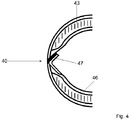
- the problem with bonding the two rotor half shells 43, 46 along the rotor blade nose 40 is that the two edges conventionally provide a relatively small adhesive surface. Therefore, the other rotor blade half shell 46 is provided with a glue lip 47, i. H. the other rotor blade half shell 46 is made longer in the direction of a rotor blade half shell 43 than would be necessary for a frontal superimposition of the edges of the rotor blade half shells 43, 46.
- the adhesive lip 47 of the other rotor blade half shell 46 is pushed past the inside of the one rotor blade half shell 43 when the two half shells 3, 6 are pivoted together, and an outer side of the adhesive lip 47 is glued to an inner side of a rotor blade shell 43.
- the rotor blade nose 40 after gluing has, if possible, no offset along an adhesive line 41 on an outer skin 42, the pressure-side mold half-shell 6, gem.
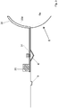
- Fig. 3 During the manufacture of the other rotor blade half shell 46 equipped with a Klebelippenform 30.
- the adhesive lip mold 30 is a component which is arranged only during the production of the other rotor blade half shell 46 on the trough-shaped centering 4 of the centering device 1 of the suction half-shell mold 6 and after the production of the other rotor blade half shell 46 again from the suction-side mold half shell 6 is removed before the two half-shells 3, 6 are folded up.
- the adhesive lip mold 30 continues through its inner support surface 30a, the support surface 6a of the other mold half-shell 6 upwards, ie in a direction that would show in the direction of a mold half-shell 3 in the folded state.
- the adhesive lip mold 30 makes it possible to provide the rotor blade half shell 46 with the lip 47 required for the bonding.
- the adhesive lip mold 30 is positioned exactly on one of the mold half shells 3, 6, preferably on the other mold half shell 6, temporarily by providing the adhesive lip mold 30 itself with a further centering piece 31, preferably a modified, pin-like centering piece also cooperates with the trough-shaped centering 4.
- the centering device 1 can already be used during the manufacture of the rotor blade half shells 43, 46, in order to allow an exact positioning of the lip 47 of the other rotor blade half shell 46.
- the adhesive lip mold 30 additionally has one or more magnets 33 arranged in the longitudinal direction L, which are arranged on the metallically formed inserts of the other mold half-shell 6 and thus additionally hold the adhesive lip mold 30 in position.
- the centering device 1 prevents slippage in the horizontal direction, ie in the plane of the mold half-shell 6, but no slippage in the vertical direction, ie perpendicular to the plane of the other mold half-shell 6.
Landscapes
- Engineering & Computer Science (AREA)
- Mechanical Engineering (AREA)
- Life Sciences & Earth Sciences (AREA)
- Sustainable Development (AREA)
- Sustainable Energy (AREA)
- Chemical & Material Sciences (AREA)
- Combustion & Propulsion (AREA)
- General Engineering & Computer Science (AREA)
- Wind Motors (AREA)
Abstract
Description
- Die Erfindung betrifft eine Fertigungsform eines Rotorblattes einer Windenergieanlage. Die Erfindung betrifft auch ein Verfahren zur Fertigung eines Rotorblattes einer Windenergieanlage.
- Fertigungsformen zur Fertigung von Rotorblättern sind im Stand der Technik natürlich bekannt. Dabei werden Rotorblätter durch Zusammenfügen zweier Rotorblatthalbschalen hergestellt. Die Rotorblatthalbschalen werden separat voneinander in Formhalbschalen jeweils in einem Verfahren gefertigt, in dem die Faserhalbzeuge durch Laminieren, Infusionieren oder durch die Verwendung von Prepregs mit Harz getränkt und ausgehärtet werden. Nach dem Aushärten der Rotorblatthalbschalen werden die Formhalbschalen aufeinandergeklappt, dabei wird üblicherweise die zur Herstellung der saugseitigen Rotorblatthalbschale verwendete saugseitige Halbschalenform über die positionsfest verbleibende druckseitige Halbschalenform mittels eines Schwenkmechanismus verschwenkt.
- Moderne Rotorblätter weisen Längen von 70 m und mehr auf, die entsprechenden Formhalbschalen weisen daher ebenfalls Längen von deutlich über 70 m auf. Beim Aufeinanderschwenken der beiden Formhalbschalen müssen die Rotorblatthalbschalen positionsgenau übereinander positioniert sein, um ein Verkleben der beiden Rotorblatthalbschalen zu ermöglichen. Zur exakten Positionierung der Formschalen zueinander sind sogenannte Zentriereinrichtungen vorgesehen, die aus einem männlichen, stiftartigen Zentrierstück und einem weiblichen, pfannenartigen Zentrierstück bestehen, die beim Ausrichten der beiden Formhalbschalen zueinander zusammenwirken und durch das Eigengewicht der Formschalen und evtl. zusätzliche äußere Kräfte eine exakte Positionierung der beiden Formhalbschalen zueinander gewährleisten. Dazu müssen die Zentriereinrichtungen vorab natürlich genau eingestellt werden.
- Selbst bei einer positionsgenauen Zentrierung der Rotorblatthalbschalen übereinander, hat sich gezeigt, dass eine Verklebung lediglich anhand der frontal aufeinanderliegenden Rotorblatthalbschalenränder eine sehr geringe und teilweise zu geringe Klebfläche zur Verfügung stellt, um eine dauerhafte und feste Verklebung zu gewährleisten.
- Daher ist es ebenfalls bekanntermaßen vorgesehen, an einer der beiden Rotorblatthalbschalen entlang der Nase eine sogenannte Klebelippe bereits während der Herstellung der jeweiligen der Rotorblatthalbschale integral mit der Rotorblatthalbschale auszubilden. Die Klebelippe wird innenseitig an die andere Rotorblatthalbschale angeklebt, wenn die beiden Rotorblatthalbschalen mit Hilfe der Formen, in denen sie sich dann noch befinden, zueinander positioniert und miteinander verklebt werden. Dadurch vergrößert sich die Klebfläche zwischen beiden Rotorblatthalbschalen an der Profilvorderkante erheblich.
- Bei dem durch den Stand der Technik bekannten Verfahren wird die Klebelippenform soweit in Richtung Hinterkante des Blattes verschoben, wie es der Gesamtdicke der gegenüberliegenden Blattschale an der Vorderkante entspricht, plus der gewünschten Klebedicke. Dieses Verfahren führt zu großen Steifigkeitssprüngen am Ende der gegenüberliegenden Blattschale und dazu, dass es an der Blattschale mit der integrierten Klebelippe entweder ebenfalls zu einem großen Steifigkeitssprung kommt, wenn die Schalenlagen alle in der Trennebene enden und die Lagen für die Klebelippe als separate Lagen eingelegt werden oder zu einer großen Umlenkung und Krümmung der Faserlagen, wenn die Schalenlagen in die Klebelippe verlängert werden.
- Aufgabe der Erfindung ist es daher, eine Fertigungsform eines Rotorblattes einer Windenergieanlage sowie ein Fertigungsverfahren für ein Rotorblatt zur Verfügung zu stellen, die bzw. das in der Lage sind, die oben genannten Nachteile zu vermeiden.
- Die Aufgabe wird in ihrem ersten Aspekt durch eine eingangs genannte Fertigungsform mit den Merkmalen des Anspruchs 1 erreicht.
- Die erfindungsgemäße Fertigungsform weist eine Formhalbschale und eine andere Formhalbschale auf und mindestens eine Zentriereinrichtung mit einem Zentrierstück und einem korrespondierendem Zentrierstück auf, von denen das eine Zentrierstück an der einen Formhalbschale und das korrespondierende Zentrierstück an der anderen Formhalbschale oder umgekehrt angeordnet sind. Die Fertigungsform weist darüber hinaus eine Klebelippenform mit einem weiteren Zentrierstück auf, das während der Fertigung einer Rotorblatthalbschale an der zugehörigen Formhalbschale zeitweise angeordnet ist, wobei das weitere Zentrierstück der Klebelippenform und das korrespondierende Zentrierstück der anderen Formhalbschale zusammenwirken.
- Die erfindungsgemäße Klebelippenform macht sich damit die an der Formhalbschale und der anderen Formhalbschale ohnehin angeordnete Zentriereinrichtung anderweitig zu Nutze, indem eines der beiden Zentrierstücke zu Montage der Klebelippenform verwendet wird. Das an der Klebelippenform angeordnete weitere Zentrierstück wirkt zeitweise mit dem korrespondierenden Zentrierstück während der Fertigung der Rotorblatthalbschale zusammen.
- Grundsätzlich ist hier unter einer Rotorblatthalbschale bzw. Formhalbschale eine Anordnung zu verstehen, die einen Teil des Rotorblattes ausbildet. Dabei kann es sich um exakt eine Hälfte eines Rotorblattes handeln; es ist jedoch auch denkbar, dass ein kleinerer oder größerer Teil des Rotorblattes durch eine Formhalbschale gefertigt wird. Es ist auch denkbar, dass sogar lediglich ein Abschnitt oder Streifen entlang der Rotorblattnase durch eine Formhalbschale gefertigt werden, sodass der Begriff "halb" nicht als "hälftig" zu verstehen ist, sondern auch größere oder kleinere Teile umfassen kann.
- Darüber hinaus ist es grundsätzlich offen, ob die Klebelippenform an der einen oder der anderen Formhalbschale zeitweise angeordnet ist. Je nach Anordnung an der Klebelippenform an der einen Formhalbschale oder an der anderen Formhalbschale weist die Klebelippenform ein weiteres Zentrierstück oder ein weiteres korrespondierendes Zentrierstück auf.
- Günstigerweise vergrößert die Klebelippenform eine andere Auflagefläche der anderen Formhalbschale in eine Richtung, in der die eine Formhalbschale bei aufeinandergeklappten Formhalbschalen angeordnet ist. Die Klebelippenform ist erfindungsgemäß so gewählt, dass sie entlang eines Randes der anderen Formhalbschale angeordnet ist und die durch die andere Formhalbschale ausgebildete andere Rotorblatthalbschale mit einer Klebelippe versieht, die beim Zusammenfügen der Rotorblatthalbschalen nicht einen Teil der Rotorblattaußenhaut ausbildet, sondern innen hinter die eine Rotorblatthalbschale greift und damit eine vergrößerte Klebfläche zwischen Innenwandung der einen Rotorblatthalbschale und Außenwandung der Klebelippe erzeugt.
- Gegenüber dem Stand der Technik ist die Klebelippenform jedoch dadurch, dass sie ein weiteres Zentrierstück aufweist und an dem korrespondierenden Zentrierstück der Formhalbschale angeordnet ist und mit ihm zusammenwirkt, besonders exakt zu positionieren. Es ist dadurch möglich, die Klebelippe unmittelbar am anderen Formhalbschalenrand derart auszubilden, dass die Klebelippe unmittelbar am gegenüberliegenden Halbschalenrand der gegenüber liegenden Blatthalbschale nach innen, in die Blatthalbschale hinein, versetzt angeordnet ist und sich dadurch ein sehr gut definierter und gleichmäßiger Klebespalt ergibt. Die Auflagefläche der Klebelippenform, welche die Verklebung der Blattschalen an der Profilvorderkante begrenzt, ist also nicht exakt bündig mit der Auflagefläche der anderen Formhalbschale ausgebildet, sondern ein Stück weit nach innen versetzt, wobei die erfindungsgemäße Ausführung den Versatz unmittelbar an der Profilvorderkante gegenüber dem Stand der Technik durch das Versetzen der Enden der Schalenlagen auf ein Minimum reduziert wird und so die oben beschriebenen Nachteile vermieden werden. Durch die erfindungsgemäße Anordnung der Klebelippenform an der Zentriereinrichtung ist es erst möglich, diese sehr präzise Ausbildung des Versatzes entlang der gesamten Rotorblattnase zu ermöglichen.
- Günstigerweise weist die Klebelippenform wenigstens einen Magneten zur Fixierung der Klebelippenform auf dem Rand der anderen auf. Die bekannten Zentriereinrichtungen zeichnen sich insbesondere dadurch aus, dass sie eine Zentrierung in der Profiltiefenrichtung ermöglichen. Durch das Einsetzen der Klebelippenform mittels eines weiteren Zentrierstückes in das korrespondierende Zentrierstück, bleibt auch die Klebelippenform grundsätzlich entlang der Vertikalen frei beweglich. Lediglich die Beweglichkeit in der Profiltiefenrichtung ist fixiert und ermöglicht die genaue Positionierung der Klebelippenform relativ zum anderen Formhalbschalenrand. Um auch die Beweglichkeit in der Vertikalen zu fixieren, sind Magneten vorgesehen, die integral mit der Klebelippenform ausgebildet sind und die an der metallischen anderen Formhalbschale zeitweise fixiert werden können.
- Die Zentriereinrichtungen können unterschiedlich ausgebildet sein, vorzugsweise ist das Zentrierstück wannenförmig ausgebildet und das korrespondierende Zentrierstück stiel- oder stiftförmig ausgebildet oder umgekehrt, es sind noch andere Ausbildungen zweier korrespondierender Zentrierstücke denkbar, die eine Positionierung der beiden Bauteile beim Ineinanderfügen der beiden Zentrierstücke ermöglichen. Günstigerweise handelt es sich dabei zum einen um eine konisch ausgeformte Pfanne und zum anderen um einen entsprechend konisch spitz zulaufenden Stift.
- Die Aufgabe wird in ihrem zweiten Aspekt durch ein eingangs genanntes Verfahren mit den Merkmalen des Anspruchs 7 erfüllt.
- Das erfindungsgemäße Verfahren eignet sich insbesondere zu Durchführung mit einer der oben genannten Fertigungsformen.
- Erfindungsgemäß werden eine und eine andere Formhalbschale zur Verfügung gestellt, eine Klebelippenform wird mit einem weiteren Zentrierstück an einem korrespondierenden Zentrierstück wenigstens einer Zentriereinrichtung an der anderen Formhalbschale angeordnet und darin eine andere Rotorblatthalbschale mit einer Klebelippe gefertigt. Eine Formhalbschale wird zur Verfügung gestellt und eine Rotorblatthalbschale in der Formhalbschale gefertigt, die Klebelippenform von der anderen Formhalbschale entfernt und die beiden Formhalbschalen werden zusammengefügt, und die Klebelippe der anderen Rotorblatthalbschale hintergreift eine Rotorblatthalbschale innen entlang der vorzugsweise gesamten Rotorblattnase.
- Vorzugsweise werden Schalenlagen beider Rotorblatthalbschalen an der Nase zur Trennebene hin versetzt gelegt, sodass sich eine Art Schäftung ergibt und die Rotorblatthalbschalen mit jeweils deutlich weniger Schalenlagen an der Trennebene enden, als es ihrer Anzahl in einem im Querschnitt mittleren Bereich entspricht. Die Rotorblatthalbschalen werden zur Nase hin zunächst dünner gefertigt.
- Das erfindungsgemäße Verfahren zeichnet sich dadurch aus, dass die Klebelippenform mittels eines weiteren Zentrierstückes, das an der Klebelippenform angeordnet ist, in das an der anderen Formhalbschale ohnehin vorhandene korrespondierende Zentrierstück der wenigstens einen Zentriereinrichtung eingreift oder mit ihm zusammenwirkt.
- Die Klebelippenform dient zur Ausbildung der Klebelippe der anderen Rotorblatthalbschale.
- Gegenüber bekannten Herstellungsverfahren ist das erfindungsgemäße Verfahren deutlich präziser, da die Klebelippe, durch die Zentriervorrichtung, welche hochpräzise gefertigt und eingestellt werden kann, entlang des anderen Formhalbschalenrandes positioniert wird.
- Nach Entfernen der Klebelippenform und dem Fertigen der beiden Rotorblatthalbschalen werden die Formhalbschale und die anderen Formhalbschale zusammengefügt, und dabei wirken die Zentrierstücke und die korrespondierenden Zentrierstücke der Zentriereinrichtung zusammen und positionieren die Formhalbschalen exakt zueinander.
- Die Zentriereinrichtung hat damit gegenüber dem Stand der Technik zwei Funktionen: Zum einen die Klebelippenform exakt zu positionieren und zum anderen nach Entfernen der Klebelippenform nach wie vor die beiden Formhalbschalen zueinander exakt zu positionieren.
- In einer besonders vorteilhaften Ausbildung der erfindungsgemäßen Konfiguration wird das Zentrierstück als einstellbarer, männlicher, im Wesentlichen stiftförmiger Teil der Zentriervorrichtung in der Klebelippenform platziert, und das wannenartige, nicht einstellbare, weibliche korrespondierende Zentrierstück wird im Rand der anderen Formhalbschale platziert. Dementsprechend wird im Rand der einen Formhalbschale das Zentrierstück als ebenfalls einstellbares, männliches, im Wesentlichen stiftförmigen Teil, korrespondierend platziert.
- Vorzugsweise wird die Klebelippenform mit einem stiftartigen weiteren Zentrierstück in ein wannenförmiges Zentrierstück eingebracht und mit Magneten an der Formhalbschale zusätzlich befestigt. Durch die Befestigung mit den Magneten wird auch eine Fixierung senkrecht zur Ebene der Formhalbschale ermöglicht, die durch die bekannten Zentriereinrichtungen bisher nicht möglich war.
- Die Erfindung wird anhand eines Ausführungsbeispiels in vier Figuren beschrieben. Dabei zeigt
- Fig. 1
- eine schematische Schnittansicht einer Zentriereinrichtung,
- Fig. 2
- eine schematische perspektivische Ansicht eines saugschalenseitigen Zentrierstücks der Zentriereinrichtung,
- Fig. 3
- eine schematische Schnittansicht des saugseitigen Zentrierstücks gemäß
Fig. 2 mit der erfindungsgemäßen Klebelippenform, - Fig. 4
- eine Nasenverklebung einer saugseitigen und einer druckseitigen Rotorblatthalbschale.
- Rotorblattschalen werden mithilfe einer vorzugsweise mehrteiligen Fertigungsform gefertigt. Die Fertigungsform umfasst eine saugseitige Formhalbschale und eine druckseitige Formhalbschale. Üblicherweise sind die beiden Formhalbschalen mittels einer Scharniervorrichtung aufeinanderklappbar. In der druckseitigen Formhalbschale wird die druckseitige Rotorblatthalbschale und in der saugseitigen Formhalbschale wird die sauseitige Rotorblatthalbschale in einem Laminierverfahren gefertigt, indem die Faserhalbzeuge durch Laminieren, Infusionieren oder durch die Verwendung von Prepregs mit Harz getränkt und ausgehärtet werden.
- Die vorgefertigten Rotorblatthalbschalen werden durch eine Schwenkbewegung einer der Formhalbschalen übereinandergeschwenkt, sodass die Ränder der Rotorblatthalbschalen direkt aufeinander positioniert sind. Die Ränder werden dann vorzugsweise mit einem Klebstoffsystem zusammengeklebt.
-
Fig. 1 zeigt eine Zentriereinrichtung 1 mit einem stiftartigen Zentrierstück 2, der mit einer Formhalbschale 3 verbunden ist und einem wannenartigen Zentrierstück 4, das mit einer anderen Formhalbschale 6 verbunden ist. Das stiftartige Zentrierstück 2 und das wannenartige Zentrierstück 4 bilden zusammen eine Zentriereinrichtung 1 aus. Die Zentriereinrichtung 1 ermöglicht es und gewährleistet es, dass die beiden Formhalbschalen 3, 6 beim Zusammenklappen positionsgenau gegeneinander ausgerichtet werden, indem eine Spitze 7 des stiftartigen Zentrierstücks 2 in die etwa komplementär geformte Wanne des wannenartigen Zentrierstückes 4 eingeführt wird und dabei die beiden Zentrierstücke 2 und 4 gegeneinander ausrichtet, sodass eine Auflagefläche 3a der druckseitigen Formhalbschale 3 und eine Auflagefläche 6a der saugseitigen Formhalbschale 6 gemäßFig. 1 exakt bündig gegeneinander ausgerichtet sind. - Die Formhalbschalen 3, 6 sind in
Fig. 1 nach rechts, also der Zentriereinrichtung 1 an den beiden Nasenabschnitten der Auflageflächen 3,a, 6a gegenüberliegend, weit ausgedehnt und voneinander beabstandet, sodass rechts der Zentriereinrichtung 1 vollständige Auflageflächen 3a, 6a für die Rotorblatthabschalen angeordnet sind. - Die beiden Formhalbschalen 3, 6 weisen im zusammengeklappten Zustand gemäß
Fig. 1 einen kleinen Spalt 8 von 1 mm bis 3 mm zwischen sich auf, durch den das Klebmittel, das beim Zusammenklappen der beiden nicht eingezeichneten Rotorblatthalbschalen innen- und außenseitig aus dem Rotorblatt herausgedrückt wird, ausweichen kann. - Die Formhalbschalen 3, 6 weisen darüber hinaus Kanalprofile 9 auf, durch die ein Vakuum entlang der Formhalbschalen 3, 6 verteilt werden kann.
- Das stiftartige Zentrierstück 2, ist beispielsweise durch eine Reihe von (nicht dargestellten) Schrauben in der Höhe, also in Richtung des wannenartigen Zentrierstückes 4 einstellbar, aber auch in horizontaler Richtung d. h. parallel zum wannenartigen Zentrierstück 4 einstellbar. Nach dem Einstellen behält die Spitze 7 des Zentrierstücks 2 ihre Position relativ zur Formhalbschale 3 bei. Durch exaktes Einstellen ist eine positionsgenaue Anordnung der beiden Zentrierstücke 2, 4 relativ zueinander zu gewährleisten, damit die beiden Auflageflächen 3a, 6a der zugehörigen Formhalbschale 3, 6 entlang der Rotorblattnase exakt miteinander fluchten.
- In
Fig. 2 ist das wannenartige Zentrierstück 4 an der saugseitigen Formhalbschale 6 in einer perspektivischen Ansicht dargestellt. Die Wanne oder Pfanne, Mulde oder Einbuchtung verjüngt sich und ist bei einem Formhalbschalenrand 6b angeordnet. - Problematisch beim Verkleben der beiden Rotorblatthalbschalen 43, 46 entlang der Rotorblattnase 40 ist, dass die beiden Ränder herkömmlicherweise eine relativ kleine Klebfläche zur Verfügung stellen. Daher wird die andere Rotorblatthalbschale 46 mit einer Klebelippe 47 versehen, d. h. die andere Rotorblatthalbschale 46 wird in Richtung der einen Rotorblatthalbschale 43 länger gefertigt als es für ein frontales Aufeinanderkleben der Ränder der Rotorblatthalbschalen 43, 46 erforderlich wäre.
- Die Klebelippe 47 der anderen Rotorblatthalbschale 46 wird innen an der einen Rotorblatthalbschale 43 beim Aufeinanderschwenken der beiden Formhalbschalen 3, 6 vorbeigeschoben, und eine Außenseite der Klebelippe 47 wird an eine Innenseite der einen Rotorblatthalbschale 43 angeklebt.
- Damit die Rotorblattnase 40 nach dem Verkleben nach Möglichkeit keinen Versatz entlang einer Klebelinie 41 an einer Außenhaut 42 aufweist, ist die druckseitige Formhalbschale 6, gem.
Fig. 3 , während der Fertigung der anderen Rotorblatthalbschale 46 mit einer Klebelippenform 30 bestückt. Die Klebelippenform 30 ist ein Bauteil, das lediglich während der Fertigung der anderen Rotorblatthalbschale 46 auf dem wannenförmigen Zentrierstück 4 der Zentriereinrichtung 1 der saugseitigen Halbschalenform 6 angeordnet wird und nach der Fertigung der anderen Rotorblatthalbschale 46 wieder von der saugseitigen Formhalbschale 6 entfernt wird, bevor die beiden Formhalbschalen 3, 6 aufeinandergeklappt werden. Die Klebelippenform 30 setzt durch ihre innere Auflagefläche 30a die Auflagefläche 6a der anderen Formhalbschale 6 nach oben hin fort, d. h. in eine Richtung, die im zusammengeklappten Zustand in Richtung der einen Formhalbschale 3 zeigen würde. Die Klebelippenform 30 ermöglicht es, die Rotorblatthalbschale 46 mit der zur Verklebung erforderlichen Lippe 47 zu versehen. - Erfindungsgemäß ist es vorgesehen, dass die Klebelippenform 30 exakt auf einer der Formhalbschalen 3, 6, vorzugsweise auf der anderen Formhalbschale 6, zeitweise positioniert wird, indem die Klebelippenform 30 selbst mit einem weiteren Zentrierstück 31, vorzugsweise einem abgewandelten, stiftartigen Zentrierstück versehen wird, das ebenfalls mit dem wannenförmigen Zentrierstück 4 zusammenwirkt.
- Dadurch kann die Zentriereinrichtung 1 bereits während der Fertigung der Rotorblatthalbschalen 43, 46 genutzt werden, um eine genaue Positionierung der Lippe 47 der anderen Rotorblatthalbschale 46 zu ermöglichen.
- Günstigerweise weist die Klebelippenform 30 zusätzlich einen oder mehrere in Längsrichtung L angeordnete Magnete 33 auf, die auf den metallisch ausgebildeten Inserts der anderen Formhalbschale 6 angeordnet werden und damit die Klebelippenform 30 zusätzlich in Position halten. Das ist insbesondere deshalb notwendig, weil die Zentriereinrichtung 1 zwar ein Verrutschen in horizontaler Richtung, d. h. in der Ebene der Formhalbschale 6 verhindert, aber kein Verrutschen in senkrechter Richtung, d. h. senkrecht zur Ebene der anderen Formhalbschale 6. Nach der Fertigung der saugseitigen Rotorblatthalbschale 46 wird die Klebelippenform 30 in
Fig. 3 von rechts nach links durch eine Schwenkbewegung abgezogen und das stiftartige weitere Zentrierstück 31 aus der Pfanne 4 herausgezogen, und durch eine Hebebewegung werden die Magneten 33 von der anderen Formhalbschale 6 gelöst. -
- 1
- Zentriereinrichtung
- 2
- stiftartiges Zentrierstück
- 3
- eine Formhalbschale
- 3a
- Auflagefläche der einen Formhalbschale
- 4
- wannenartiges Zentrierstück
- 6
- andere Formhalbschale
- 6a
- Auflagefläche der anderen Formhalbschale
- 7
- konische Spitze
- 8
- Spalt
- 9
- Kanalprofile
- 30
- Klebelippenform
- 30a
- Auflagefläche
- 31
- weiteres Zentrierstück
- 33
- Magneten
- 40
- Rotorblattnase
- 41
- Klebelinie
- 42
- Außenhaut
- 43
- eine Rotorblatthalbschale
- 46
- andere Rotorblatthalbschale
- 47
- Klebelippe
- L
- Längsrichtung
Claims (11)
- Fertigungsform eines Rotorblattes einer Windenergieanlage
mit einer Formhalbschale (3) und
einer anderen Formhalbschale (6) und
mindestens einer Zentriereinrichtung (1) mit einem Zentrierstück (2) und einem korrespondierenden Zentrierstück (4), von denen das eine Zentrierstück (2) an der einen Formhalbschale (3) und das korrespondierende Zentrierstück (4) an der anderen Formhalbschale (6) oder umgekehrt angeordnet sind, und
einer Klebelippenform (30) mit einem weiteren Zentrierstück (31), das während der Fertigung einer Rotorblatthalbschale (43, 46) an der einen Formhalbschale (3) zeitweise angeordnet ist, und dabei wirken das weitere Zentrierstück (31) und das korrespondierende Zentrierstück (4) zusammen. - Fertigungsform nach Anspruch 1,
dadurch gekennzeichnet, dass die Klebelippenform (30) eine Auflagefläche der einen Formhalbschale (3) in eine Richtung vergrößert, in der die andere Formhalbschale (6) bei aufeinandergeklappten Formhalbschalen (3, 6) angeordnet ist. - Fertigungsform nach Anspruch 1 oder 2,
dadurch gekennzeichnet, dass die Klebelippenform (30) unmittelbar am Formhalbschalenrand (6b) der anderen Formhalbschale (6) nach innen in die andere Formhalbschale (6) hinein versetzt angeordnet ist. - Fertigungsform nach einem der Ansprüche 1, 2 oder 3,
dadurch gekennzeichnet, dass die Klebelippenform (30) an einem dem Formhalbschalenrand (6b) abgewandten Ende wenigstens einen Magneten (33) zur Fixierung an der anderen Formhalbschale (6) aufweist. - Fertigungsform nach einem der Ansprüche 1 bis 4,
dadurch gekennzeichnet, dass die eine Formhalbschale (3) eine druckseitige Formhalbschale und die andere Formhalbschale (6) eine saugseitige Formhalbschale ist. - Fertigungsform nach einem der vorstehenden Ansprüche,
dadurch gekennzeichnet, dass das korrespondierende Zentrierstück (4) wannenförmig ausgebildet ist und das Zentrierstück (2) stiftförmig ausgebildet ist. - Verfahren zur Fertigung eins Rotorblattes einer Windenergieanlage, indem eine Formhalbschale (3) und eine andere Formhalbschale (6) und
mindestens eine Zentriereinrichtung (1) mit einem Zentrierstück (2) und einem korrespondierenden Zentrierstück (4), von denen das eine Zentrierstück (2) an der einen Formhalbschale (3) und das korrespondierende Zentrierstück (4) an der anderen Formhalbschale (6) oder umgekehrt angeordnet sind, zur Verfügung gestellt wird, eine Klebelippenform (30) mit einem weiteren Zentrierstück (31) an dem korrespondierenden Zentrierstück (4) der wenigstens einen Zentriereinrichtung (1) angeordnet wird,
eine andere Rotorblatthalbschale (46) in der anderen Formhalbschale (6) mit einer Klebelippe (47) gefertigt wird,
eine Rotorblatthalbschale (43) in der einen Formhalbschale (3) gefertigt wird und die Klebelippenform (30) entfernt wird und die beiden Formhalbschalen (3, 6) zusammengefügt werden und die Klebelippe (47) der anderen Rotorblatthalbschale (46) innen hinter die eine Rotorblatthalbschale (43) greift. - Verfahren nach Anspruch 7,
dadurch gekennzeichnet, dass entlang einer Nase (40) der anderen Rotorblatthalbschale (46) die Klebelippe (47) gefertigt wird, die am anderen Rotorblatthalbschalenrand nach innen versetzt angeordnet wird und die Nase (40) der Rotorblatthalbschale (43) hintergreift und ein Rotorblatthalbschalenrand der Rotorblatthalbschale (43) und ein Rotorblatthalbschalenrand der anderen Rotorblatthalbschale (46) entlang der Nase (40) unmittelbar nebeneinander angeordnet werden. - Verfahren nach Anspruch 7 oder 8,
dadurch gekennzeichnet, dass Schalenlagen beider Rotorblatthalbschalen (43, 46) an der Nase (40) zu einer Trennebene hin versetzt gelegt werden. - Verfahren nach Anspruch 7 bis 9,
dadurch gekennzeichnet, dass die Klebelippenform (30) mit dem Zentrierstück (2), das stiftartig ausgebildet ist, in das korrespondierende Zentrierstück (4), das wannenförmig ausgebildet ist, eingebracht wird und mit Magneten (33) an der anderen Formhalbschale (6) zusätzlich befestigt wird. - Verfahren nach einem der Ansprüche 7 bis 10,
dadurch gekennzeichnet, dass die eine Formhalbschale (3) und die andere Formhalbschale (6) zusammengefügt werden und dabei die Zentrierstücke (2) und die korrespondierenden Zentrierstücke (4) zusammenwirken und die Formhalbschalen (3, 6) zueinander positionieren.
Applications Claiming Priority (1)
| Application Number | Priority Date | Filing Date | Title |
|---|---|---|---|
| DE102016011450.9A DE102016011450A1 (de) | 2016-09-22 | 2016-09-22 | Feinzentrierung für Vorderkantenklebelippenform |
Publications (1)
| Publication Number | Publication Date |
|---|---|
| EP3299148A1 true EP3299148A1 (de) | 2018-03-28 |
Family
ID=59856395
Family Applications (1)
| Application Number | Title | Priority Date | Filing Date |
|---|---|---|---|
| EP17190305.7A Withdrawn EP3299148A1 (de) | 2016-09-22 | 2017-09-11 | Feinzentrierung für vorderkantenklebelippenform |
Country Status (2)
| Country | Link |
|---|---|
| EP (1) | EP3299148A1 (de) |
| DE (1) | DE102016011450A1 (de) |
Families Citing this family (1)
| Publication number | Priority date | Publication date | Assignee | Title |
|---|---|---|---|---|
| DE102018006165A1 (de) | 2018-08-06 | 2020-02-06 | Senvion Gmbh | Rotorblatt mit Verklebungen mit kontinuierlich veränderlichen Breiten und ein Herstellungsverfahren für ein Rotorblatt |
Citations (3)
| Publication number | Priority date | Publication date | Assignee | Title |
|---|---|---|---|---|
| EP2305998A2 (de) * | 2009-09-29 | 2011-04-06 | Vestas Wind Systems A/S | Form zur Herstellung von Windturbinenschaufeln |
| WO2013001458A2 (en) * | 2011-06-27 | 2013-01-03 | Iq Tec Switzerland Gmbh | Preforming pre-preg |
| WO2014079458A1 (en) * | 2012-11-20 | 2014-05-30 | Vestas Wind Systems A/S | Wind turbine blade with lightning protection |
Family Cites Families (3)
| Publication number | Priority date | Publication date | Assignee | Title |
|---|---|---|---|---|
| DE2421936B2 (de) * | 1974-05-07 | 1976-06-10 | Speidel-Kunststoffwerk Kg, 7404 Ofterdingen | Verfahren zum stoss- an stoss-verbinden der raender von raeumlich gekruemmten schalenelementen aus glasfaserverstaerktem kunststoff und vorrichtung dazu |
| DE102006025666B4 (de) * | 2006-06-01 | 2009-07-16 | Lisa Dräxlmaier GmbH | Kaschierung mit verminderter Klebkraft |
| DE102012003378B4 (de) * | 2012-02-22 | 2015-01-29 | Nordex Energy Gmbh | Verfahren zum Herstellen einer Blindverklebung zwischen zwei Bauteilen eines Windenergieanlagenrotorblatts |
-
2016
- 2016-09-22 DE DE102016011450.9A patent/DE102016011450A1/de not_active Withdrawn
-
2017
- 2017-09-11 EP EP17190305.7A patent/EP3299148A1/de not_active Withdrawn
Patent Citations (3)
| Publication number | Priority date | Publication date | Assignee | Title |
|---|---|---|---|---|
| EP2305998A2 (de) * | 2009-09-29 | 2011-04-06 | Vestas Wind Systems A/S | Form zur Herstellung von Windturbinenschaufeln |
| WO2013001458A2 (en) * | 2011-06-27 | 2013-01-03 | Iq Tec Switzerland Gmbh | Preforming pre-preg |
| WO2014079458A1 (en) * | 2012-11-20 | 2014-05-30 | Vestas Wind Systems A/S | Wind turbine blade with lightning protection |
Also Published As
| Publication number | Publication date |
|---|---|
| DE102016011450A1 (de) | 2018-03-22 |
Similar Documents
| Publication | Publication Date | Title |
|---|---|---|
| DE102011078951B4 (de) | Verfahren zum Herstellen eines Rotorblatts für eine Windenergieanlage, Sandwich-Preform und Rotorblatt für eine Windenergieanlage | |
| EP3018342B2 (de) | Verfahren zum herstellen eines rotorblatts einer windenergieanlage | |
| EP2321105B1 (de) | Verfahren und fertigungsform zur fertigung eines rotorblattes für eine windenergieanlage | |
| EP2261501B1 (de) | Verfahren und Vorrichtung zur Montage eines Rotorblatts für eine Windenergieanlage | |
| EP3114348B1 (de) | Verfahren zum herstellen eines rotorblatts einer windenergieanlage, rotorblatt und windenergieanlage | |
| DE102014001445B4 (de) | Vorrichtung zur Herstellung von Rotorblattschalen | |
| EP2666615B1 (de) | Verfahren zur Herstellung einer Windenergieanlagenrotorblatthalbschale bzw. eines Windenergieanlagenrotorblatts und Herstellungsform zu diesem Zweck | |
| EP3003601B1 (de) | Speisereinsatz, formelement für den speisereinsatz und verfahren zum giessen von metall unter verwendung derselben | |
| DE102007060029A1 (de) | Verfahren und Vorrichtung zur Herstellung röhrenförmiger Strukturbauteile | |
| DE102008021788A1 (de) | Verfahren zum Reparieren einer Flugzeugkomponente | |
| EP2454472A2 (de) | Rotorblatt einer windenergieanlage sowie verfahren zum fertigen eines rotorblattes einer windenergieanlage | |
| DE102012204858A1 (de) | Fertigung eines Faserverbundbauteils für ein Rotorblatt | |
| EP3078587B1 (de) | Flügelkörper | |
| DE102015007289A1 (de) | Rotorblatt, Rotorblattgurt und Verfahren zum Herstellen eines Rotorblattgurts | |
| EP3074183B1 (de) | Stegsetzvorrichtung, steg und fertigungsverfahren für ein rotorblatt einer windenergieanlage | |
| WO2016030459A1 (de) | Verfahren und vorrichtung zur herstellung von formteilen | |
| EP2662204A1 (de) | Verfahren, vorgefertiges Bauelement und Form zur Herstellung eines Windenergieanlagenbauteils | |
| EP3752732B1 (de) | Verfahren zur herstellung eines geteilten rotorblatts und rotorblatt | |
| DE102012003378B4 (de) | Verfahren zum Herstellen einer Blindverklebung zwischen zwei Bauteilen eines Windenergieanlagenrotorblatts | |
| EP3634730A1 (de) | Verfahren zum herstellen eines windenergieanlagen-rotorblattes | |
| DE102016011450A1 (de) | Feinzentrierung für Vorderkantenklebelippenform | |
| WO2014095856A2 (de) | Variable formvorrichtung zur herstellung einer halbschale für ein rotorblatt für eine windenergieanlage | |
| DE102017001402A1 (de) | Zentriereinrichtung an der Hinterkante der Formhalbschalen | |
| DE2002361B2 (de) | Verfahren zur Herstellung eines Kamera-Suchergehäuses aus Kunststoff und Vorrichtung zur Durchführung des Verfahrens | |
| DE2346181B2 (de) | Verfahren zur Herstellung eines Leistens für die Schuhherstellung, sowie Gießform hierfür |
Legal Events
| Date | Code | Title | Description |
|---|---|---|---|
| PUAI | Public reference made under article 153(3) epc to a published international application that has entered the european phase |
Free format text: ORIGINAL CODE: 0009012 |
|
| STAA | Information on the status of an ep patent application or granted ep patent |
Free format text: STATUS: THE APPLICATION HAS BEEN PUBLISHED |
|
| AK | Designated contracting states |
Kind code of ref document: A1 Designated state(s): AL AT BE BG CH CY CZ DE DK EE ES FI FR GB GR HR HU IE IS IT LI LT LU LV MC MK MT NL NO PL PT RO RS SE SI SK SM TR |
|
| AX | Request for extension of the european patent |
Extension state: BA ME |
|
| STAA | Information on the status of an ep patent application or granted ep patent |
Free format text: STATUS: REQUEST FOR EXAMINATION WAS MADE |
|
| 17P | Request for examination filed |
Effective date: 20180912 |
|
| RBV | Designated contracting states (corrected) |
Designated state(s): AL AT BE BG CH CY CZ DE DK EE ES FI FR GB GR HR HU IE IS IT LI LT LU LV MC MK MT NL NO PL PT RO RS SE SI SK SM TR |
|
| GRAP | Despatch of communication of intention to grant a patent |
Free format text: ORIGINAL CODE: EPIDOSNIGR1 |
|
| STAA | Information on the status of an ep patent application or granted ep patent |
Free format text: STATUS: GRANT OF PATENT IS INTENDED |
|
| INTG | Intention to grant announced |
Effective date: 20201104 |
|
| STAA | Information on the status of an ep patent application or granted ep patent |
Free format text: STATUS: THE APPLICATION IS DEEMED TO BE WITHDRAWN |
|
| 18D | Application deemed to be withdrawn |
Effective date: 20210316 |