EP3486476B1 - Steg für ein rotorblatt einer windenergieanlage und verfahren zum herstellen eines stegs - Google Patents
Steg für ein rotorblatt einer windenergieanlage und verfahren zum herstellen eines stegs Download PDFInfo
- Publication number
- EP3486476B1 EP3486476B1 EP18206399.0A EP18206399A EP3486476B1 EP 3486476 B1 EP3486476 B1 EP 3486476B1 EP 18206399 A EP18206399 A EP 18206399A EP 3486476 B1 EP3486476 B1 EP 3486476B1
- Authority
- EP
- European Patent Office
- Prior art keywords
- shear web
- core
- web
- form part
- face
- Prior art date
- Legal status (The legal status is an assumption and is not a legal conclusion. Google has not performed a legal analysis and makes no representation as to the accuracy of the status listed.)
- Active
Links
- 238000004519 manufacturing process Methods 0.000 title claims description 11
- 239000000463 material Substances 0.000 claims description 15
- 239000000835 fiber Substances 0.000 claims description 9
- 239000011162 core material Substances 0.000 description 103
- 239000010410 layer Substances 0.000 description 34
- 239000002657 fibrous material Substances 0.000 description 22
- 230000007704 transition Effects 0.000 description 9
- 239000003365 glass fiber Substances 0.000 description 6
- 239000003822 epoxy resin Substances 0.000 description 4
- 238000000034 method Methods 0.000 description 4
- 229920000647 polyepoxide Polymers 0.000 description 4
- 229920005830 Polyurethane Foam Polymers 0.000 description 3
- 239000011496 polyurethane foam Substances 0.000 description 3
- 239000012790 adhesive layer Substances 0.000 description 2
- 239000007788 liquid Substances 0.000 description 2
- 238000000465 moulding Methods 0.000 description 2
- 230000000284 resting effect Effects 0.000 description 2
- 241000196324 Embryophyta Species 0.000 description 1
- 240000007182 Ochroma pyramidale Species 0.000 description 1
- 239000000853 adhesive Substances 0.000 description 1
- 238000004026 adhesive bonding Methods 0.000 description 1
- 230000001070 adhesive effect Effects 0.000 description 1
- 230000005540 biological transmission Effects 0.000 description 1
- 239000006260 foam Substances 0.000 description 1
- 239000006261 foam material Substances 0.000 description 1
- 238000009434 installation Methods 0.000 description 1
- 239000011344 liquid material Substances 0.000 description 1
- 239000004814 polyurethane Substances 0.000 description 1
- 229920002635 polyurethane Polymers 0.000 description 1
- 229920005989 resin Polymers 0.000 description 1
- 239000011347 resin Substances 0.000 description 1
- 230000000087 stabilizing effect Effects 0.000 description 1
Images


Classifications
-
- F—MECHANICAL ENGINEERING; LIGHTING; HEATING; WEAPONS; BLASTING
- F03—MACHINES OR ENGINES FOR LIQUIDS; WIND, SPRING, OR WEIGHT MOTORS; PRODUCING MECHANICAL POWER OR A REACTIVE PROPULSIVE THRUST, NOT OTHERWISE PROVIDED FOR
- F03D—WIND MOTORS
- F03D1/00—Wind motors with rotation axis substantially parallel to the air flow entering the rotor
- F03D1/06—Rotors
- F03D1/065—Rotors characterised by their construction elements
- F03D1/0675—Rotors characterised by their construction elements of the blades
-
- F—MECHANICAL ENGINEERING; LIGHTING; HEATING; WEAPONS; BLASTING
- F05—INDEXING SCHEMES RELATING TO ENGINES OR PUMPS IN VARIOUS SUBCLASSES OF CLASSES F01-F04
- F05B—INDEXING SCHEME RELATING TO WIND, SPRING, WEIGHT, INERTIA OR LIKE MOTORS, TO MACHINES OR ENGINES FOR LIQUIDS COVERED BY SUBCLASSES F03B, F03D AND F03G
- F05B2230/00—Manufacture
- F05B2230/30—Manufacture with deposition of material
- F05B2230/31—Layer deposition
-
- F—MECHANICAL ENGINEERING; LIGHTING; HEATING; WEAPONS; BLASTING
- F05—INDEXING SCHEMES RELATING TO ENGINES OR PUMPS IN VARIOUS SUBCLASSES OF CLASSES F01-F04
- F05B—INDEXING SCHEME RELATING TO WIND, SPRING, WEIGHT, INERTIA OR LIKE MOTORS, TO MACHINES OR ENGINES FOR LIQUIDS COVERED BY SUBCLASSES F03B, F03D AND F03G
- F05B2240/00—Components
- F05B2240/20—Rotors
- F05B2240/30—Characteristics of rotor blades, i.e. of any element transforming dynamic fluid energy to or from rotational energy and being attached to a rotor
-
- Y—GENERAL TAGGING OF NEW TECHNOLOGICAL DEVELOPMENTS; GENERAL TAGGING OF CROSS-SECTIONAL TECHNOLOGIES SPANNING OVER SEVERAL SECTIONS OF THE IPC; TECHNICAL SUBJECTS COVERED BY FORMER USPC CROSS-REFERENCE ART COLLECTIONS [XRACs] AND DIGESTS
- Y02—TECHNOLOGIES OR APPLICATIONS FOR MITIGATION OR ADAPTATION AGAINST CLIMATE CHANGE
- Y02E—REDUCTION OF GREENHOUSE GAS [GHG] EMISSIONS, RELATED TO ENERGY GENERATION, TRANSMISSION OR DISTRIBUTION
- Y02E10/00—Energy generation through renewable energy sources
- Y02E10/70—Wind energy
- Y02E10/72—Wind turbines with rotation axis in wind direction
-
- Y—GENERAL TAGGING OF NEW TECHNOLOGICAL DEVELOPMENTS; GENERAL TAGGING OF CROSS-SECTIONAL TECHNOLOGIES SPANNING OVER SEVERAL SECTIONS OF THE IPC; TECHNICAL SUBJECTS COVERED BY FORMER USPC CROSS-REFERENCE ART COLLECTIONS [XRACs] AND DIGESTS
- Y02—TECHNOLOGIES OR APPLICATIONS FOR MITIGATION OR ADAPTATION AGAINST CLIMATE CHANGE
- Y02P—CLIMATE CHANGE MITIGATION TECHNOLOGIES IN THE PRODUCTION OR PROCESSING OF GOODS
- Y02P70/00—Climate change mitigation technologies in the production process for final industrial or consumer products
- Y02P70/50—Manufacturing or production processes characterised by the final manufactured product
Definitions
- the invention relates to a web for a rotor blade of a wind power plant and a method for producing such a web.
- a rotor of a wind energy plant usually comprises a plurality of rotor blades which are connected to a hub of the rotor.
- the rotor is rotated by the wind so that, for example, a generator can be driven via a rotor shaft in order to generate electrical energy.
- the rotor blade should be able to withstand the forces which act on the rotor blade during operation of the wind energy installation.
- the weight of the rotor blade should be as low as possible.
- the rotor blade can be constructed as a shell with a shell part on the suction side and a shell part on the pressure side, between which a cavity is enclosed.
- a web is a component that extends in the cavity of the rotor blade and creates a stabilizing connection between the suction-side shell part and the pressure-side shell part.
- the web can be aligned approximately in the longitudinal direction of the rotor blade and can extend over a substantial part of the length of the rotor blade between the rotor blade root and the rotor blade tip.
- the web has the purpose, among other things, of transferring shear forces from the suction-side shell part into the pressure-side shell part and of keeping the suction-side shell part and the pressure-side shell part at the correct distance from one another, i.e. transmitting tensile forces and pressure forces between the two shell parts.
- the web can be connected to the first shell part via a first web foot and to the second shell part via a second web foot.
- a web body can be arranged between the two web feet.
- the web Since a certain contact surface is required for the connection to a shell part, the web usually has a greater width in the region of the web foot than in the region of the web core. Examples such bridges are in DE 10 2011 082 664 A1 and DE 10 2012 223 707 A1 described.
- document EP 2 881 237 A1 describes a method for producing a web from a shear body and a foot flange, the shear body and the foot flange being connected to one another via fiber layers and resin.
- the invention has for its object to provide a web and a manufacturing method so that the web can be manufactured inexpensively and with the required stability.
- the web according to the invention comprises a web body, in the interior of which a web core is arranged, and a web foot, in the interior of which a molded part is arranged.
- the molded part widens from an end face facing the web core to a support surface.
- the invention has recognized that the web can be inexpensively manufactured with such a web core and such a molded part, with a uniform flow of force resulting within the web.
- the end face of the molded part is dimensioned and arranged in such a way that it covers the width of the web core.
- the end face of the molded part is therefore at least as wide as the web core against which the molded part rests.
- the extent of the end face in the width dimension can be somewhat larger than the width of the web core, for example up to 10% larger, preferably up to 5% larger.
- the height dimension of the web is the direction in which the molded part and the web core lie one above the other.
- the width is aligned perpendicular to it.
- the height and the width together form the cross section of the web.
- the longitudinal direction of the web extends perpendicular to the cross section.
- the web core is held by the molded part at a distance from the support surface, the smallest distance between the web core and the contact surface is at least as large as the smallest distance between the end face and the contact surface.
- the end face of the molded part can comprise a section which lies opposite an apex line of the web core.
- the end face of the molding can Cross section considered include a section that intersects the height dimension perpendicular.
- the end face of the molded part can be designed such that it engages around an end section of the web core.
- An end section is a region of the web core which is oriented in the direction of a shell part of the rotor blade when the web is connected to the rotor blade. In this assembled state, the connection between the bridge core of the bridge and the shell part of the rotor blade is established via the bridge foot.
- the molded part engages around an end section of the web core, the molded part follows the contour of the web core in two lateral directions, starting from an apex of the end section, which is the smallest distance from the shell part of the rotor blade.
- the degrees of connection can be set such that the distance between the degrees of connection and the apex of the web core corresponds to at least 10%, preferably at least 20%, further preferably at least 40% of the thickness of the web core.
- the contact surface of the molded part faces the inner surface of the adjacent shell part of the rotor blade when the web is inserted into the rotor blade.
- An adhesive layer can be arranged between the contact surface of the molded part and the inner surface of the rotor blade, through which the web is connected to the shell part.
- the end face of the molded part and / or the end section of the web core can have the shape of a circular segment in cross section.
- One of the bodies can be curved outwards and the other body can be curved inwards so that the inwards curved body can grip around the outwardly curved body.
- the radius of the outwardly curved segment of the circle can be slightly smaller than the radius of the inwardly curved segment of the circle, so that the circular segments fit into one another, taking into account any layers of fiber material arranged in between. If the circular segment of the inwardly curved body extends over an angle of extends less than 180 °, the angular alignment between the web core and the molded part can be adjusted.
- the circle segment of the inwardly curved body can for example extend over an angle between 90 ° and 170 °, preferably between 120 ° and 160 °. An angle of 360 ° would correspond to a complete circle on this scale.
- the web core is curved outwards and the molded part is curved inwards.
- the circular segment can extend over the entire width of the end face of the molded part. It is also possible that the end face of the molded part has a larger width than the circular segment.
- the end face of the molded part can have the shape of a groove which faces the web core.
- a central region of the channel can lie opposite an apex line of the web core.
- the two legs of the channel can grip around the end section of the web core.
- the end section of the web core can correspond in cross section to the shape of a segment of a circle. In one embodiment, the circular segment extends over 180 ° and connects two mutually parallel side surfaces of the web core.
- the web foot can comprise a support surface, the shape of which is predetermined by the support surface of the molded part.
- the support surface of the web foot can only be separated from the support surface of the molded part by one or more layers of a fiber material.
- the bearing surface of the web base can face the inner surface of the shell part of the rotor blade when the web is mounted in the rotor blade.
- a plane parallel to the inner surface of the shell part can be defined with the support surface.
- the molded part can comprise a first flank, which extends between the support surface and the web core. When viewed in cross section of the web, the first flank can form an angle with the contact surface of between 30 ° and 60 °, preferably between 40 ° and 50 °.
- the molded part can have a rounded edge, which forms the transition between the contact surface and the first flank.
- the radius of the edge rounding can be, for example, between 1 mm and 20 mm.
- the width of the contact surface can be, for example, between 30 mm and 300 mm.
- the distance between the contact surface of the molded part and the apex line of the web core adjacent to the molded part can be, for example, between 5 mm and 150 mm.
- the first flank can have a section that is flat.
- the flat section can extend from the transition region to the contact surface to the core-side end of the first flank.
- the first flank when viewed in cross section, comprises a concave section. Concave means that there is a degree of connection between two points on the flank that the molded part does not intersect.
- the first flank of the molded part can end at its core end in a direction that is parallel to the side surface of the web core, that is to say forms an angle of 0 ° with the side surface of the web.
- An angle of 0 ° is advantageous for the transfer of forces between the web core and the molded part, however, inaccurate manufacturing can easily lead to an offset between the core-side end of the first flank and the side surface of the web core. This is undesirable.
- the angle between the core-side end of the first flank and the side surface of the web core is somewhat larger than 0 °, for example larger than 2 °, preferably larger than 5 °. If the angle is too large, the power transmission deteriorates.
- the angle is therefore preferably not greater than 20 °, more preferably not greater than 10 °.
- the molded part can comprise a second flank, which extends between the support surface and the web core.
- the second flank can have one or more features that are disclosed in connection with the first flank.
- the core-side end of the first flank and the core-side end of the second flank can enclose the end section of the web core between them.
- the transition between the second flank and the contact surface is designed differently than the transition between the first flank and the contact surface.
- the molded part can have a non-rounded edge between the second flank and the contact surface.
- the second flank can end with a flat section or with a concave section in the direction of the bearing surface.
- the contact surface and the second flank can enclose an angle of between 10 ° and 60 °, preferably between 20 ° and 50 °, for example in the transition region.
- the web core and the molded part are clad in one or more layers of a fiber material, for example in the form of glass fiber mats.
- the fiber material extends from the first side surface of the web core over the first flank of the molded part and the contact surface of the molded part.
- the transition between the first flank and the contact surface of the molded part is designed in such a way that the fiber material can be guided around without a sharp kink.
- the fiber material can extend beyond the end of the molded part.
- the fiber material can also extend from the second side surface of the web core over the second flank of the molded part. If the fiber material extends beyond the end of the molded part, it can overlap with the end of the fiber material coming from the contact surface.
- the number of layers of fiber material that lies on the side surface of the web core and on the flank of the molded part can be, for example, between 2 and 4. This can apply to the first flank and / or the second flank of the molded part.
- the molding may include one or more layers of fibrous material that extend from the first side surface of the land core around the end portion of the land core to the second side surface of the land core. These layers of the fiber material are therefore in one Intermediate space between the end portion of the web core and the molded part.
- a layer or two Extend layers of the fiber material can end at a distance between 100 mm and 500 mm from the apex line of the bar core.
- the fiber material can be impregnated with a liquid material which, when cured, gives the web stability.
- the curing material can be an epoxy resin, for example.
- the web core can consist of a sandwich core material, the density of which can be, for example, between 40 kg / m 3 and 150 kg / m 3 .
- Foam materials PET, PVC, SAN
- balsa wood for example, have such a low density.
- the sandwich core material can have an elastic modulus between 20 MPa and 200 MPa based on the height dimension of the web.
- the shear strength of the sandwich core material can be, for example, between 0.5 MPa and 2 MPa.
- the molded part can consist of a material whose density and / or whose modulus of elasticity are greater than in the sandwich core material.
- the density of the molded part can be between 150 kg / m 3 and 1200 kg / m 3 , preferably between 150 kg / m 3 and 300 kg / m 3 .
- the modulus of elasticity of the molded part can be between 1000 MPa and 6000 MPa and is therefore of the same order of magnitude as the modulus of elasticity of the adhesive which is used for gluing to the shell part of the rotor blade.
- the molded part consists of high-density polyurethane foam (HD-PU) with a density between 150 kg / m 3 and 300 kg / m 3 .
- the polyurethane foam can be fiber-reinforced. If the molded part consists of pure polyurethane, the density can be of the order of 1000 kg / m 3 .
- the web according to the invention can comprise a first molded part and a second molded part, which are arranged such that they enclose the web core between them.
- the second molded part can have one or more features that are described in connection with the first molded part.
- the molded parts can be aligned such that the first flank of the first molded part is arranged on the same side of the web as the first flank of the second molded part.
- the locations of the fiber material can extend around the entire web and lie flat on the two molded parts or the web core. Apart from overlaps following the first flank of the first molded part and following the first flank of the second molded part, the fiber material can continuously follow the contour of the web.
- the length of the web can be greater than 10 m, preferably greater than 20 m, more preferably greater than 50 m.
- the width of the web core can vary over the length of the web. Width of the web core denotes the dimension oriented perpendicular to the height, the height of the web extending between the two molded parts.
- the width of the ridge may be greater in an area near the leaf root than in an area near the tip of the leaf.
- the web core can be designed in such a way that the width of the web core changes continuously over the length of the web.
- the web core can be designed in such a way that the width of the web core changes suddenly at one or more points. It is then possible to assemble the web core from a plurality of plane-parallel plates of the sandwich core material. In an area in which a plate of reduced thickness abuts a plate of greater thickness, the width of the web core changes abruptly. It is also possible that a compensation ramp is formed in the area of such a transition, which may have a slope between 1: 5 and 1:20, for example.
- the web core can for example comprise plates with a thickness of approx. 10 mm, plates with a thickness of approx. 20 mm and / or plates with a thickness of approx. 30 mm.
- the plate thicknesses used for the web core can be, for example, between 8 mm and 60 mm.
- the molded part preferably extends without interruption over the entire length of the web. If the molded part has a channel for receiving an end section of the web core, the width of the channel can be adapted to the width of the web core. In particular, the width of the trough can taper from an area near the blade root to an area near the blade tip. The The taper can be designed continuously, that is, without sudden changes in the width of the channel. It is also possible that the width of the channel changes abruptly to match the thickness changes in the web core.
- the contact surface of the first molded part can be aligned parallel to the contact surface of the second molded part.
- the contact surfaces can enclose a right angle or an angle deviating from the right angle with the height of the web core. It is also possible that the two contact surfaces are not aligned parallel to one another, but instead form an angle with one another, which can be, for example, between 5 ° and 20 °.
- both contact surfaces form an angle of 90 ° or less with the height of the web core.
- both contact surfaces form an angle of 90 ° or more with the height of the web core.
- the first contact surface forms an angle of less than 90 ° and the second contact surface forms an angle of more than 90 ° with the height of the web core.
- the orientation of the two contact surfaces relative to one another can remain unchanged over the length of the web. It is also possible that the orientation of the two contact surfaces changes relative to one another over the length of the web.
- the distance between the two contact surfaces (based on the height of the web) can decrease with increasing distance from the leaf root.
- the invention also relates to a rotor blade for a wind turbine.
- the rotor blade comprises a shell part on the suction side and a shell part on the pressure side.
- the two shell parts are connected to one another at a front edge of the rotor blade and at a rear edge of the rotor blade and enclose a cavity between them.
- a web according to the invention is arranged in the cavity, wherein a support surface of a first molded part of the web is connected to the suction-side shell part and a support surface of a second molded part of the web is connected to the pressure-side shell part.
- the length of the web can extend over at least 80%, preferably at least 90%, of the length of the rotor blade.
- the rotor blade can comprise a plurality of webs which are aligned essentially parallel to one another.
- the rotor blade can be divided into a plurality of chambers by the webs, each chamber being delimited by two webs and by a section of the suction-side shell part and a section of the pressure-side shell part.
- the contact surface of the first molded part can be glued flat to the suction side shell part.
- the bearing surface of the second molded part can be glued flat to the second shell part.
- the invention also relates to a method for producing a web.
- one or more layers of a fiber material are placed in a mold.
- a first molded part and a second molded part are placed on the layers of the fiber material, so that the end faces of the molded parts face one another and that the contact surfaces of the molded parts face away from one another.
- a web core is inserted into the mold so that the web core is arranged between the two end faces of the molded parts.
- the web core is inserted into the mold in such a way that a first end section of the web core is encompassed by the end face of the first molded part and that a second end section of the web core is encompassed by the end face of the second molded part.
- One or more further layers of the fiber material can be inserted into the mold in such a way that the fiber material extends from the second flank of the first molded part over the web core to the second flank of the second molded part.
- the layers can extend beyond the first molded part and / or the second molded part, so that there is an overlap with the layers inserted first.
- a material in particular an epoxy resin, can be introduced into the mold in liquid form and harden in order to fix the web core, the first molded part, the second molded part and the fiber material relative to one another.
- the shape can be free of an undercut so that the finished bar can be easily removed from the mold.
- a further layer of the fiber material is inserted into the mold, which layer extends between the first molded part and the web core and / or between the second molded part and the web core.
- the method can be further developed with further features which are described in connection with the web according to the invention.
- the web can be further developed with further features that are described in connection with the method according to the invention.
- a wind turbine comprises according to Fig. 1 a gondola 14 which is rotatably mounted on a tower 15.
- the gondola carries one in Fig. 1 Invisible rotor shaft to which a rotor 16 is connected.
- the rotor 16 comprises a plurality of rotor blades 17.
- the rotor 16 is rotated by the wind and drives a generator via the rotor shaft to generate electrical energy.
- Each rotor blade 17 extends between a blade root 18, which is connected to a hub 19 of the rotor 16, and a blade tip 20, see Fig. 2 .
- the rotor blade 17 is composed of a suction-side shell part 21 and a pressure-side shell part 22.
- the two shell parts 21, 22 are connected to one another on a front edge 23 and on a rear edge 24 of the rotor blade 17.
- the shell parts 21, 22 enclose a cavity between them, which forms an interior of the rotor blade 17.
- Each bridge 25, 26 comprises a bridge core 27 and two bridge feet 28, 29.
- the bridge feet 28, 29 are wider than the bridge core 27, so that a stable connection to the inner surfaces of the shell parts 21, 22 can be formed via the bridge feet 28, 29 .
- a corresponding adhesive layer 33 for establishing the connection between the web foot 29 and the inner surface of the shell part 22 is shown in FIG Fig. 4 shown.
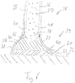
- the bridge foot 29 comprises a molded part 30 which extends between a support surface 31 and an end surface 32 which is shaped as a groove.
- the groove 32 opposite the support surface 31 has the shape of a circular segment in cross section, which extends over an angle of approximately 150 °. With the groove 32, the molded part 30 engages around a lower end section 34 of the web core 27.
- the lower end section 34 of the web core 27 is semicircular in cross section and merges into two flat side surfaces 35, 36 of the web core 27.
- the web core 27 can be pivoted within the groove 32 in order to adjust the orientation of the web core 27 relative to the contact surface 31.
- the radius of the lower end section 34 is somewhat smaller than the radius of the groove 32, so that a fiber layer 42 can be passed between the web core 27 and the groove 32.
- the molded part 30 comprises a first flank 37, which extends between the support surface 31 and the groove 32. Viewed in cross section, the first flank 37 is flat and goes with a rounded edge 38 into the bearing surface 31. The other end of the first flank 37 runs straight towards the web core 27 and forms an angle of approximately 45 ° with the side surface 35 of the web core.
- the opposite second flank 39 of the molded part 37 runs in a corresponding manner towards the second side surface 36 of the web core 27.
- the lower end of the second flank 39 includes a non-rounded edge 40 with the contact surface 31.
- the web core 27 and the molded part 30 are embedded in several layers of a glass fiber material, of which in Fig. 4 only one layer 41 is shown.
- the layer 41 extends from the first side surface 35 over the first flank 37 of the molded part 30, the rounded edge 38 and the contact surface 31 to beyond the lower end of the second flank 39.
- the layer 41 also extends from the second side surface 36 of the web core over the second flank 39 of the molded part 30 to beyond the lower edge of the second flank 39. In the area next to the edge 40, the two projecting ends of the layer 41 overlap.
- a further layer 42 of the glass fiber material extends from the first side surface 35 of the web core 27 through the space between the end section 34 and the groove 32 to the second side surface 36 of the Bridge core 27.
- a web according to the invention is produced in the lying state in a shape as shown in Fig. 5 is shown.
- the shape is adjusted to the desired shape of the web 26 by adjusting moving parts 42 and using inserts 43.
- the required number of layers 41 of the glass fiber material is then inserted into the mold, the layers 41 extending over the entire width of the mold.
- Two molded parts 30 are placed on the layers 41 so that the bearing surfaces 31 point outwards.
- the web core 27 is inserted into the mold, so that the two channels 32 of the molded parts 30 are gripped around the two end sections of the web core 27. This arrangement is covered from above with further layers 41 of the glass fiber material.
- the web core 27 consists of light PET foam with a modulus of elasticity of approximately 20 MPa.
- the two molded parts 30 consist of high-strength and high-density polyurethane foam with a modulus of elasticity in the order of 1000 MPa.
- the first flank 37 and the second flank 39 of the molded part 30 have a concave shape.
- the flanks 37, 39 of the molded part 30 taper toward the side surfaces 35, 36 of the web core 27, the upper ends of the flanks 37, 39 enclosing a small angle with the side surfaces 35, 36.
- this results in an approximately continuous transition between the molded part 30 and the web core 27, which is advantageous for the force flow and the stability of the web 27.
- the lower end of the second flank 39 also ends in a curve.
- the layers 41 resting on the second flank 39 and the layers 41 resting on the support surface 31 can merge into the overlap without a step or kink, which is also advantageous for the force flow and the stability of the web 27.
Description
- Die Erfindung betrifft einen Steg für ein Rotorblatt einer Windenergieanlage und ein Verfahren zum Herstellen eines solchen Stegs.
- Ein Rotor einer Windenergieanlage umfasst regelmäßig eine Mehrzahl von Rotorblättern, die an eine Nabe des Rotors angeschlossen sind. Der Rotor wird durch den Wind in Drehung versetzt, so dass über eine Rotorwelle beispielsweise ein Generator angetrieben werden kann, um elektrische Energie zu erzeugen. Das Rotorblatt soll einerseits den Kräften standhalten können, die im Betrieb der Windenergieanlage auf das Rotorblatt einwirken. Andererseits soll das Gewicht des Rotorblatts möglichst gering sein.
- Das Rotorblatt kann als Schale aufgebaut sein mit einem saugseitigen Schalenteil und einem druckseitigen Schalenteil, zwischen denen ein Hohlraum eingeschlossen ist. Als Steg wird ein Bauelement bezeichnet, das sich in dem Hohlraum des Rotorblatts erstreckt und eine stabilisierende Verbindung zwischen dem saugseitigen Schalenteil und dem druckseitigen Schalenteil herstellt. Der Steg kann ungefähr in Längsrichtung des Rotorblatts ausgerichtet sein und sich über einen wesentlichen Teil der Länge des Rotorblatts zwischen der Rotorblattwurzel und der Rotorblattspitze erstrecken.
- Der Steg hat unter anderem den Zweck, Schubkräfte von dem saugseitigen Schalenteil in das druckseitige Schalenteil zu übertragen sowie das saugseitige Schalenteil und das druckseitige Schalenteil im richtigen Abstand zueinander zu halten, also Zugkräfte und Drucckräfte zwischen den beiden Schalenteilen zu übertragen. Der Steg kann über einen ersten Stegfuß mit der ersten Schalenteil und über einen zweiten Stegfuß mit der zweiten Schalenteil verbunden sein. Zwischen den beiden Stegfüßen kann ein Stegkörper angeordnet sein.
- Da für den Anschluss an ein Schalenteil eine gewisse Auflagefläche erforderlich ist, hat der Steg im Bereich des Stegfußes üblicherweise eine größere Breite als im Bereich des Stegkerns. Beispiele solcher Stege sind in
DE 10 2011 082 664 A1 undDE 10 2012 223 707 A1 beschrieben. DokumentEP 2 881 237 A1 beschreibt ein Verfahren zum Herstellen eines Stegs aus einem Scherkörper und einem Fußflansch, wobei der Scherkörper und der Fußflansch über Faserlagen und Harz miteinander verbunden werden. - Der Erfindung liegt die Aufgabe zugrunde, einen Steg und ein Herstellungsverfahren vorzustellen, so dass der Steg kostengünstig und in der erforderlichen Stabilität hergestellt werden kann. Ausgehend vom genannten Stand der Technik wird die Aufgabe gelöst mit den Merkmalen der unabhängigen Ansprüche. Vorteilhafte Ausführungsformen sind in den Unteransprüchen angegeben.
- Der erfindungsgemäße Steg umfasst einen Stegkörper, in dessen Innerem ein Stegkern angeordnet ist, und einen Stegfuß, in dessen Innerem ein Formteil angeordnet ist. Das Formteil weitet sich von einer dem Stegkern zugewandten Stirnfläche zu einer Auflagefläche auf.
- Die Erfindung hat erkannt, dass der Steg sich mit einem solchen Stegkern und einem solchen Formteil günstig fertigen lässt, wobei sich innerhalb des Stegs ein gleichmäßiger Kraftfluss ergibt.
- Die Stirnfläche des Formteils ist in einer Ausführungsform so dimensioniert und angeordnet, dass sie die Breite des Stegkerns überdeckt. Die Stirnfläche des Formteils ist demnach mindestens so breit wie der Stegkern, an dem das Formteil anliegt. Die Erstreckung der Stirnfläche in der Breitendimension kann etwas größer sein als die Breite des Stegkerns, beispielsweise um bis zu 10% größer, vorzugsweise um bis zu 5% größer. Als Höhendimension des Stegs wird die Richtung bezeichnet, in der das Formteil und der Stegkern übereinander liegen. Die Breite ist senkrecht dazu ausgerichtet. Die Höhe und die Breite bilden gemeinsam den Querschnitt des Stegs. Die Längsrichtung des Stegs erstreckt sich senkrecht zu dem Querschnitt.
- Der Stegkern wird durch das Formteil auf Abstand von der Auflagefläche gehalten, wobei der kleinste Abstand zwischen dem Stegkern und der Auflagefläche wenigstens so groß ist wie der kleinste Abstand zwischen der Stirnfläche und der Auflagefläche. Die Stirnfläche des Formteils kann einen Abschnitt umfassen, der einer Scheitellinie des Stegkerns gegenüberliegt. Die Stirnfläche des Formteils kann im Querschnitt betrachtet einen Abschnitt umfassen, der die Höhendimension senkrecht schneidet.
- Die Stirnfläche des Formteils kann so gestaltet sein, dass sie einen Endabschnitt des Stegkerns umgreift. Als Endabschnitt wird ein Bereich des Stegkerns bezeichnet, der in Richtung eines Schalenteils des Rotorblatts ausgerichtet ist, wenn der Steg mit dem Rotorblatt verbunden ist. Über den Stegfuß wird in diesem zusammengesetzten Zustand die Verbindung zwischen dem Stegkern des Stegs und dem Schalenteil des Rotorblatts hergestellt.
- Wenn ein Formteil einen Endabschnitt des Stegkerns umgreift, so folgt das Formteil ausgehend von einem Scheitelpunkt des Endabschnitts, der den geringsten Abstand zu dem Schalenteil des Rotorblatts hat, in zwei seitlichen Richtungen der Kontur des Stegkerns. Mit anderen Worten gibt es eine Verbindungsgrade zwischen zwei Punkten des Formteils, die den Endabschnitt des Stegkerns schneidet und insbesondere eine Mittelebene des Stegkerns schneidet. In einer Ausführungsform kann die Verbindungsgrade so gelegt werden, dass der Abstand zwischen der Verbindungsgrade und dem Scheitelpunkt des Stegkerns mindestens 10%, vorzugsweise mindestens 20%, weiter vorzugsweise mindestens 40% der Dicke des Stegkerns entspricht. Die Auflagefläche des Formteils ist der Innenfläche des angrenzenden Schalenteils des Rotorblatts zugewandt, wenn der Steg in das Rotorblatt eingesetzt ist. Zwischen der Auflagefläche des Formteils und der Innenfläche des Rotorblatts kann eine Klebeschicht angeordnet sein, durch die der Steg mit dem Schalenteil verbunden wird.
- Die Stirnfläche des Formteils und/oder der Endabschnitt der Stegkerns können im Querschnitt die Form eines Kreissegments haben. Einer der Körper kann nach außen gewölbt sein und der andere Körper nach innen gewölbt sein, so dass der nach innen gewölbte Körper den nach außen gewölbten Körper umgreifen kann. Der Radius des nach außen gewölbten Kreissegments kann geringfügig kleiner sein als der Radius des nach innen gewölbten Kreissegments, so dass die Kreissegmente unter Berücksichtigung eventueller dazwischen angeordneter Lagen eines Fasermaterials gerade ineinander passen. Wenn das Kreissegment des nach innen gewölbten Körpers sich über einen Winkel von weniger als 180° erstreckt, kann die Winkelausrichtung zwischen dem Stegkern und dem Formteil angepasst werden. Das Kreissegment des nach innen gewölbten Körpers kann sich beispielsweise über einen Winkel zwischen 90° und 170°, vorzugsweise zwischen 120° und 160° erstrecken. Ein Winkel von 360° würde auf dieser Skala einem vollständigen Kreis entsprechen.
- In einer Ausführungsform ist der Stegkern nach außen gewölbt und das Formteil nach innen gewölbt. Das Kreissegment kann sich über die gesamte Breite der Stirnfläche des Formteils erstrecken. Möglich ist auch, dass die Stirnfläche des Formteils eine größere Breite hat als das Kreissegment.
- Die Stirnfläche des Formteils kann die Form einer Rinne aufweisen, die dem Stegkern zugewandt ist. Ein mittlerer Bereich der Rinne kann einer Scheitellinie des Stegkerns gegenüber liegen. Die beiden Schenkel der Rinne können den Endabschnitt des Stegkerns umgreifen. Der Endabschnitt des Stegkerns kann im Querschnitt der Form eines Kreissegments entsprechen. In einer Ausführungsform erstreckt das Kreissegment sich über 180° und verbindet zwei zueinander parallele Seitenflächen des Stegkerns.
- Der Stegfuß kann eine Auflagefläche umfassen, deren Form durch die Auflagefläche des Formteils vorgegeben ist. Die Auflagefläche des Stegfußes kann von der Auflagefläche des Formteils nur durch eine oder mehrere Lagen eines Fasermaterials getrennt ist. Die Auflagefläche des Stegfußes kann der Innenfläche des Schalenteils des Rotorblatts zugewandt sein, wenn der Steg in dem Rotorblatt montiert ist. Mit der Auflagefläche kann eine zu der Innenfläche des Schalenteils parallele Ebene definiert werden.
- Das Formteil kann eine erste Flanke umfassen, die sich zwischen der Auflagefläche und dem Stegkern erstreckt. Die erste Flanke kann im Querschnitt des Stegs betrachtet mit der Auflagefläche einen Winkel zwischen 30° und 60°, vorzugsweise zwischen 40° und 50° einschließen. Das Formteil kann eine abgerundete Kante aufweisen, die den Übergang zwischen der Auflagefläche und der ersten Flanke bildet. Der Radius der Kantenrundung kann beispielsweise zwischen 1 mm und 20 mm liegen. Die Breite der Auflagefläche kann beispielsweise zwischen 30 mm und 300 mm liegen. Der Abstand zwischen der Auflagefläche des Formteils und der an das Formteil angrenzenden Scheitellinie des Stegkerns kann beispielsweise zwischen 5 mm und 150 mm liegen.
- Die erste Flanke kann im Querschnitt betrachtet einen Abschnitt aufweisen, der eben ist. Der ebene Abschnitt kann sich von dem Übergangsbereich zu der Auflagefläche bis zum kernseitigen Ende der ersten Flanke erstrecken. In einer alternativen Ausführungsform umfasst die erste Flanke im Querschnitt betrachtet einen konkaven Abschnitt. Konkav bedeutet, dass es eine Verbindungsgrade zwischen zwei Punkten der Flanke gibt, die das Formteil nicht schneidet.
- Die erste Flanke des Formteils kann an ihrem kernseitigen Ende in einer Richtung auslaufen, die parallel zu der Seitenfläche des Stegkerns ist, also einen Winkel von 0° mit der Seitenfläche des Stegs einschließt. Für die Überleitung von Kräften zwischen dem Stegkern und dem Formteil ist ein Winkel von 0° vorteilhaft, allerdings kann es bei ungenauer Fertigung leicht zu einem Versatz zwischen dem kernseitigen Ende der ersten Flanke und der Seitenfläche des Stegkerns kommen. Dies ist unerwünscht. Für eine größere Toleranz gegenüber Fertigungsungenauigkeiten kann es deswegen von Vorteil sein, wenn der Winkel zwischen dem kernseitigen Ende der ersten Flanke und der Seitenfläche des Stegkerns etwas größer ist als 0°, beispielsweise größer ist als 2°, vorzugsweise größer ist als 5°. Bei einem zu großen Winkel wiederum verschlechtert sich die Kraftübertragung. Der Winkel ist deswegen vorzugsweise nicht größer als 20°, weiter vorzugsweise nicht größer als 10°.
- Das Formteil kann eine zweite Flanke umfassen, die sich zwischen der Auflagefläche und dem Stegkern erstreckt. Betreffend die Form, die Ausrichtung und den Übergangsbereich zu der Seitenfläche des Stegkerns kann die zweite Flanke eines oder mehrere Merkmale aufweisen, die im Zusammenhang der ersten Flanke offenbart sind. Das kernseitige Ende der ersten Flanke und das kernseitige Ende der zweiten Flanke können den Endabschnitt des Stegkerns zwischen sich einschließen.
- Der Übergang zwischen der zweiten Flanke und der Auflagefläche ist in einer Ausführungsform des Formteils anders gestaltet als der Übergang zwischen der ersten Flanke und der Auflagefläche. Insbesondere kann das Formteil zwischen der zweiten Flanke und der Auflagefläche eine nicht-abgerundete Kante aufweisen. Die zweite Flanke kann mit einem ebenen Abschnitt oder mit einem konkaven Abschnitt in Richtung der Auflagefläche auslaufen. Die Auflagefläche und die zweite Flanke können in dem Übergangsbereich beispielsweise einen Winkel zwischen 10° und 60°, vorzugsweise zwischen 20° und 50° miteinander einschließen.
- Der Stegkern und das Formteil sind erfindungsgemäß in eine oder mehrere Lagen aus einem Fasermaterial eingekleidet, zum Beispiel in Form von Glasfasermatten. Das Fasermaterial erstreckt sich von der ersten Seitenfläche des Stegkerns über die erste Flanke des Formteils und die Auflagefläche des Formteils. Hierfür ist es von Vorteil, wenn der Übergang zwischen der ersten Flanke und der Auflagefläche des Formteils so gestaltet ist, dass das Fasermaterial ohne scharfen Knick herumgeführt werden kann. Am gegenüberliegenden Ende der Auflagefläche kann das Fasermaterial sich über das Ende des Formteils hinaus erstrecken.
- Das Fasermaterial kann sich außerdem von der zweiten Seitenfläche des Stegkerns über die zweite Flanke des Formteils erstrecken. Wenn das Fasermaterial sich über das Ende des Formteils hinaus erstreckt, kann es mit dem Ende des von der Auflagefläche kommenden Fasermaterial überlappen.
- Die Anzahl der Lagen von Fasermaterial, die auf der Seitenfläche des Stegkerns und auf der Flanke des Formteils aufliegt kann beispielsweise zwischen 2 und 4 liegen. Dies kann für die erste Flanke und/oder die zweite Flanke des Formteils gelten.
Das Formteil kann eine oder mehrere Lagen von Fasermaterial umfassen, die sich von der ersten Seitenfläche des Stegkerns um den Endabschnitt des Stegkerns herum zu der zweiten Seitenfläche des Stegkerns erstrecken. Diese Lagen des Fasermaterials sind also in einem Zwischenraum zwischen dem Endabschnitt des Stegkerns und dem Formteil angeordnet. Hier können sich beispielsweise eine Lage oder zwei Lagen des Fasermaterials erstrecken. Die um den Stegkern herumgeführten Lagen können in einem Abstand zwischen 100 mm und 500 mm von der Scheitellinie des Stegkerns enden. - Bei der Herstellung des Stegs kann das Fasermaterial mit einem flüssigen Material getränkt werden, das dem Steg im ausgehärteten Zustand Stabilität verleiht. Das aushärtende Material kann beispielsweise ein Epoxidharz sein.
- Der Stegkern kann aus einem Sandwich-Kernmaterial bestehen, dessen Dichte beispielsweise zwischen 40 kg/m3 und 150 kg/m3 liegen kann. Eine derart geringe Dichte haben beispielsweise Schaummaterialien (PET, PVC, SAN) oder Balsaholz. Das Sandwich-Kernmaterial kann einen Elastizitätsmodul zwischen 20 MPa und 200 MPa bezogen auf die Höhendimension des Stegs aufweisen. Die Schubfestigkeit des Sandwich-Kernmaterials kann beispielsweise zwischen 0,5 MPa und 2 MPa liegen.
- Das Formteil kann aus einem Material bestehen, dessen Dichte und/oder dessen Elastizitätsmodul größer sind als bei dem Sandwich-Kernmaterial. Beispielweise kann die Dichte des Formteils zwischen 150 kg/m3 und 1200 kg/m3, vorzugsweise zwischen 150 kg/m3 und 300 kg/m3 liegen. Der Elastizitätsmodul des Formteils kann zwischen 1000 MPa und 6000 MPa sein und damit in der gleichen Größenordnung liegen wie der Elastizitätsmodul des Klebers, der zum Verkleben mit dem Schalenteil des Rotorblatts verwendet wird. In einer Ausführungsform besteht das Formteil aus hochdichtem Polyurethanschaum (HD-PU) mit einer Dichte zwischen 150 kg/m3 und 300 kg/m3. Der Polyurethanschaum kann faserverstärkt sein. Besteht das Formteil aus reinem Polyurethan, so kann die Dichte in der Größenordnung von 1000 kg/m3 liegen.
- Der erfindungsgemäße Steg kann ein erstes Formteil und ein zweites Formteil umfassen, die so angeordnet sind, dass sie den Stegkern zwischen sich einschließen. Das zweite Formteil kann eines oder mehrere Merkmale aufweisen, die im Zusammenhang des ersten Formteils beschrieben sind. Die Formteile können so ausgerichtet sein, dass die erste Flanke des ersten Formteils auf derselben Seite des Stegs angeordnet ist wie die erste Flanke des zweiten Formteils. Die Lagen des Fasermaterials können sich um den gesamten Steg herum erstrecken und dabei flächig auf den beiden Formteilen bzw. dem Stegkern aufliegen. Abgesehen von Überlappungen im Anschluss an die erste Flanke des ersten Formteils sowie im Anschluss an die erste Flanke des zweiten Formteils kann das Fasermaterial der Kontur des Stegs kontinuierlich folgen.
- Die Länge des Stegs kann größer sein als 10 m, vorzugsweise größer sein als 20 m, weiter vorzugsweise größer sein als 50 m. Die Breite des Stegkerns kann über die Länge des Stegs variieren. Breite des Stegkerns bezeichnet die senkrecht zur Höhe ausgerichtete Dimension, wobei die Höhe des Stegs sich zwischen den beiden Formteilen erstreckt. Die Breite des Stegs kann in einem Bereich nahe der Blattwurzel größer sein als in einem Bereich nahe der Blattspitze. Der Stegkern kann so gestaltet sein, dass die Breite des Stegkerns sich über die Länge des Stegs kontinuierlich ändert.
- Um die Fertigungskosten zu vermindern, kann der Stegkern so gestaltet sein, dass die Breite des Stegkerns sich an einer oder mehreren Stellen sprunghaft ändert. Es ist dann möglich, den Stegkern aus einer Mehrzahl von planparallelen Platten des Sandwich-Kernmaterials zusammenzusetzen. In einem Bereich, in dem eine Platte von geringerer Dicke an eine Platte von größerer Dicke stößt, ändert die Breite des Stegkerns sich sprunghaft. Möglich ist auch, dass im Bereich eines solchen Übergangs eine Ausgleichsrampe ausgebildet ist, die beispielsweise eine Steigung zwischen 1:5 und 1:20 haben kann. Der Stegkern kann beispielsweise Platten mit einer Dicke von ca. 10 mm, Platten mit einer Dicke von ca. 20 mm und/oder Platten mit einer Dicke von ca. 30 mm umfassen. Die für den Stegkern verwendeten Plattendicken können beispielsweise zwischen 8 mm und 60 mm liegen.
- Das Formteil erstreckt sich vorzugsweise ohne Unterbrechung über die gesamte Länge des Stegs. Wenn das Formteil eine Rinne zur Aufnahme eines Endabschnitts des Stegkerns aufweist, so kann die Breite der Rinne an die Breite des Stegkerns angepasst sein. Insbesondere kann die Breite der Rinne sich ausgehend von einem Bereich nahe der Blattwurzel hin zu einem Bereich nahe der Blattspitze verjüngen. Die Verjüngung kann kontinuierlich ausgestaltet sein, also ohne sprunghafte Änderungen in der Breite der Rinne. Möglich ist auch, dass die Breite der Rinne sich passend zu den Dickensprüngen des Stegkerns sprunghaft ändert.
- Im Querschnitt des Stegs betrachtet kann die Auflagefläche des ersten Formteils parallel zu der Auflagefläche des zweiten Formteils ausgerichtet sein. Die Auflageflächen können mit der Höhe des Stegkerns einen rechten Winkel oder einen vom rechten Winkel abweichenden Winkel einschließen. Möglich ist auch, dass die beiden Auflageflächen nicht parallel zueinander ausgerichtet sind, sondern einen Winkel miteinander einschließen, der beispielsweise zwischen 5° und 20° liegen kann. In einer ersten Ausführungsform schließen beide Auflageflächen einen Winkel 90° oder weniger mit der Höhe des Stegkerns. In einer zweiten Ausführungsform schließen beide Auflageflächen einen Winkel von 90° oder mehr mit der Höhe des Stegkerns ein. In einer dritten Ausführungsform schließt die erste Auflagefläche einen Winkel von weniger als 90° und die zweite Auflagefläche einen Winkel von mehr als 90° mit der Höhe des Stegkerns ein.
- Die Ausrichtung der beiden Auflageflächen relativ zueinander kann über die Länge des Stegs unverändert bleiben. Möglich ist auch, dass die Ausrichtung der beiden Auflageflächen sich über die Länge des Stegs relativ zueinander ändert. Der Abstand zwischen den beiden Auflageflächen (bezogen auf die Höhe des Stegs) kann sich mit zunehmendem Abstand von der Blattwurzel vermindert.
- Die Erfindung betrifft außerdem ein Rotorblatt für eine Windenergieanlage. Das Rotorblatt umfasst ein saugseitiges Schalenteil und ein druckseitiges Schalenteil. Die beiden Schalenteile sind an einer Vorderkante des Rotorblatts und an einer Hinterkante des Rotorblatts miteinander verbunden und schließen einen Hohlraum zwischen sich ein. In dem Hohlraum ist ein erfindungsgemäßer Steg angeordnet, wobei eine Auflagefläche eines ersten Formteils des Stegs mit dem saugseitigen Schalenteil und eine Auflagefläche eines zweiten Formteil des Stegs mit dem druckseitigen Schalenteil verbunden ist.
- Die Länge des Stegs kann sich über wenigstens 80%, vorzugweise wenigstens 90% der Länge des Rotorblatts erstrecken. Das Rotorblatt kann eine Mehrzahl von Stegen umfassen, die im Wesentlichen parallel zueinander ausgerichtet sind. Das Rotorblatt kann durch die Stege in einer Mehrzahl von Kammern unterteilt werden, wobei jede Kammer durch zwei Stege sowie durch einen Abschnitt des saugseitigen Schalenteils und einen Abschnitt des druckseitigen Schalenteils begrenzt ist. Die Auflagefläche des ersten Formteils kann flächig mit dem Saugseiten Schalenteil verklebt sein. Die Auflagefläche des zweiten Formteils kann flächig mit dem zweiten Schalenteil verklebt sein.
- Die Erfindung betrifft außerdem ein Verfahren zum Herstellen eines Stegs. Bei dem Verfahren werden eine oder mehrere Lagen eines Fasermaterials in eine Form eingelegt. Ein erstes Formteil und ein zweites Formteil werden auf die Lagen des Fasermaterials aufgelegt, so dass die Stirnflächen der Formteile einander zugewandt sind und dass die Auflageflächen der Formteile voneinander abgewandt sind. Ein Stegkern wird in die Form eingelegt, so dass der Stegkern zwischen den beiden Stirnflächen der Formteile angeordnet ist.
- In einer Ausführungsform wird der Stegkern so in die Form eingelegt, dass ein erster Endabschnitt des Stegkerns von der Stirnfläche des ersten Formteils umgriffen wird und dass ein zweiter Endabschnitt des Stegkerns von der Stirnfläche des zweiten Formteils umgriffen wird.
- Eine oder mehrere weitere Lagen des Fasermaterials können so in die Form eingelegt werden, dass das Fasermaterial sich von der zweiten Flanke des ersten Formteils über den Stegkern bis zu der zweiten Flanke des zweiten Formteils erstreckt. Die Lagen können sich über das erste Formteil und/oder das zweite Formteil hinaus erstrecken, so dass es zu einer Überlappung mit den zuerst eingelegten Lagen kommt. Ein Material, insbesondere ein Epoxidharz, kann in flüssiger Form in die Form eingebracht werden und aushärten, um den Stegkern, das erste Formteil, das zweite Formteil und das Fasermaterial relativ zueinander zu fixieren. Die Form kann frei von einer Hinterschneidung sein, so dass der fertige Steg leicht entformt werden kann.
- In einer Ausführungsform des Verfahrens wird vor dem Einlegen des Stegkerns eine weitere Lage des Fasermaterials in die Form eingelegt, die sich zwischen dem ersten Formteil und dem Stegkern und/oder zwischen dem zweiten Formteil und dem Stegkern erstreckt.
- Das Verfahren kann mit weiteren Merkmalen fortgebildet werden, die im Zusammenhang des erfindungsgemäßen Stegs beschrieben sind. Der Steg kann mit weiteren Merkmalen fortgebildet werden, die im Zusammenhang des erfindungsgemäßen Verfahrens beschrieben sind.
- Die Erfindung wird nachfolgend unter Bezugnahme auf die beigefügten Zeichnungen anhand vorteilhafter Ausführungsformen beispielhaft beschrieben. Es zeigen:
- Fig. 1:
- eine Seitenansicht einer Windenergieanlage mit einem erfindungsgemäßen Rotorblatt;
- Fig. 2:
- eine schematische Darstellung eines erfindungsgemäßen Rotorblatts;
- Fig. 3:
- einen Schnitt entlang Linie A-Ain
Fig. 2 (vergrößert); - Fig. 4:
- einen erfindungsgemäßen Steg in Querschnittsdarstellung;
- Fig. 5:
- einen Schritt bei der Fertigung eines erfindungsgemäßen Stegs;
- Fig. 6:
- die Ansicht gemäß
Fig. 4 bei einer anderen Ausführungsform der Erfindung. - Eine Windenergieanlage umfasst gemäß
Fig. 1 eine Gondel 14, die drehbar auf einem Turm 15 gelagert ist. Die Gondel trägt eine inFig. 1 nicht sichtbare Rotorwelle, an die ein Rotor 16 angeschlossen ist. Der Rotor 16 umfasst eine Mehrzahl von Rotorblättern 17. Durch Drehen der Gondel 14 relativ zu dem Turm 15 wird der Rotor 16 in Windrichtung ausgerichtet. Der Rotor 16 wird durch den Wind in Drehung versetzt und treibt über die Rotorwelle einen Generator an, um elektrische Energie zu erzeugen. - Jedes Rotorblatt 17 erstreckt sich zwischen einer Blattwurzel 18, die an eine Nabe 19 des Rotor 16 angeschlossen ist, und einer Blattspitze 20, siehe
Fig. 2 . Wie die Schnittdarstellung inFig. 3 zeigt, ist das Rotorblatt 17 aus einem saugseitigen Schalenteil 21 und einem druckseitigen Schalenteil 22 zusammengesetzt. Die beiden Schalenteile 21, 22 sind an einer Vorderkante 23 sowie an einer Hinterkante 24 des Rotorblatts 17 miteinander verbunden. Die Schalenteile 21, 22 schließen zwischen sich einen Hohlraum ein, der einen Innenraum des Rotorblatts 17 bildet. - In dem Hohlraum sind zwei Stege 25, 26 angeordnet, die sich über nahezu die gesamte Länge des Rotorblatts 17 von der Blattwurzel 18 bis zur Blattspitze 20 erstrecken. Jeder Steg 25, 26 umfasst einen Stegkern 27 sowie zwei Stegfüße 28, 29. Die Stegfüße 28, 29 sind breiter als der Stegkern 27, so dass über die Stegfüße 28, 29 eine stabile Verbindung zu den Innenflächen der Schalenteile 21, 22 gebildet werden kann. Eine entsprechende Klebstoffschicht 33 zum Herstellen der Verbindung zwischen dem Stegfuß 29 und der Innenfläche des Schalenteils 22 ist in
Fig. 4 dargestellt. - In der vergrößerten Schnittdarstellung gemäß
Fig. 4 ist nur der untere Fuß 29 des Stegs 26 gezeigt. Der Stegfuß 29 umfasst ein Formteil 30, das sich zwischen einer Auflagefläche 31 und einer Stirnfläche 32 erstreckt, die als Rinne geformt ist. Die der Auflagefläche 31 gegenüberliegende Rinne 32 hat im Querschnitt die Form eines Kreissegments, das sich über einen Winkel von etwa 150° erstreckt. Mit der Rinne 32 umgreift das Formteil 30 einen unteren Endabschnitt 34 des Stegkerns 27. - Der untere Endabschnitt 34 des Stegkerns 27 ist im Querschnitt halbkreisförmig und geht über in zwei ebene Seitenflächen 35, 36 des Stegkerns 27. Der Stegkern 27 kann innerhalb der Rinne 32 geschwenkt werden, um die Ausrichtung des Stegkerns 27 relativ zu der Auflagefläche 31 anzupassen. Der Radius des unteren Endabschnitts 34 ist etwas kleiner als der Radius der Rinne 32, so dass eine Faserschicht 42 zwischen dem Stegkern 27 und der Rinne 32 hindurchgeführt werden kann.
- Das Formteil 30 umfasst eine erste Flanke 37, die sich zwischen der Auflagefläche 31 und der Rinne 32 erstreckt. Die erste Flanke 37 ist im Querschnitt betrachtet eben und geht mit einer abgerundeten Kante 38 in die Auflagefläche 31 über. Das andere Ende der ersten Flanke 37 läuft gerade auf den Stegkern 27 zu und schließt mit der Seitenfläche 35 des Stegkerns einen Winkel von etwa 45° ein.
- Die gegenüberliegende zweite Flanke 39 des Formteils 37 läuft in entsprechender Weise auf die zweite Seitenfläche 36 des Stegkerns 27 zu. Das untere Ende der zweiten Flanke 39 schließt mit der Auflagefläche 31 eine nicht abgerundete Kante 40 ein.
- Der Stegkern 27 und das Formteil 30 sind eingebettet in mehrere Lagen eines Glasfasermaterials, von denen in
Fig. 4 nur eine Lage 41 dargestellt ist. Die Lage 41 erstreckt sich von der ersten Seitenfläche 35 über die erste Flanke 37 des Formteils 30, die abgerundete Kante 38 und die Auflagefläche 31 bis über das untere Ende der zweiten Flanke 39 hinaus. Auf der anderen Seite des Stegs 26 erstreckt die Lage 41 sich von der zweiten Seitenfläche 36 des Stegkerns über die zweite Flanke 39 des Formteils 30 ebenfalls bis über die untere Kante der zweiten Flanke 39 hinaus. Im Bereich neben der Kante 40 überlappen die beiden überstehenden Enden der Lage 41. Eine weitere Lage 42 des Glasfasermaterials erstreckt sich von der ersten Seitenfläche 35 des Stegkerns 27 durch den Zwischenraum zwischen dem Endabschnitt 34 und der Rinne 32 hindurch bis zu der zweiten Seitenfläche 36 des Stegkerns 27. - Hergestellt wird ein erfindungsgemäßer Steg im liegenden Zustand in einer Form, wie sie in
Fig. 5 dargestellt ist. Die Form wird durch Einstellen von beweglichen Teilen 42 und unter Verwendung von Einsatzstücken 43 an die gewünschte Gestalt des Stegs 26 angepasst. In die Form wird dann die erforderliche Anzahl von Lagen 41 des Glasfasermaterials eingelegt, wobei die Lagen 41 sich über die gesamte Breite der Form erstrecken. Auf die Lagen 41 werden zwei Formteile 30 aufgelegt, so dass die Auflageflächen 31 nach außen weisen. Nach dem Einbringen einer weiteren Lage 41, die die Rinnen 32 der beiden Formteile 30 abdeckt, wird der Stegkern 27 in die Form eingeführt, so dass die beiden Endabschnitte des Stegkerns 27 von den beiden Rinnen 32 der Formteile 30 umgriffen werden. Diese Anordnung wird von oben mit weiteren Lagen 41 des Glasfasermaterials abgedeckt. Am oberen Ende der beiden Formteile 30 überlappen die zuerst eingelegten Lagen 41 mit den zuletzt eingelegten Lagen 41. Das Ganze wird mit einem Epoxidharz in flüssiger Form getränkt. Nach dem Aushärten des Epoxidharzes sind die Teile relativ zueinander stabilisiert und bilden einen stabilen Steg 26. - Der Stegkern 27 besteht in dem Ausführungsbeispiel aus leichtem PET-Schaum mit einem Elastizitätsmodul von etwa 20 MPa. Die beiden Formteile 30 bestehen aus hochfestem und hochdichtem Polyurethanschaum mit einem Elastizitätsmodul in der Größenordnung von 1000 MPa.
- Bei der alternativen Ausführungsform eines Stegs 29 in
Fig. 6 haben die erste Flanke 37 und die zweite Flanke 39 des Formteils 30 eine konkave Form. Die Flanken 37, 39 des Formteils 30 laufen mit einer Rundung auf die Seitenflächen 35, 36 des Stegkerns 27 zu, wobei die oberen Enden der Flanken 37, 39 einen kleinen Winkel mit den Seitenflächen 35, 36 einschließen. Für die Lagen 41 des Glasfasermaterials ergibt sich damit ein annähernd kontinuierlicher Übergang zwischen dem Formteil 30 und dem Stegkern 27, was für den Kraftfluss und die Stabilität des Stegs 27 von Vorteil ist. - Das untere Ende der zweiten Flanke 39 läuft ebenfalls in einer Rundung aus. Die auf der zweiten Flanke 39 und die auf der Auflagefläche 31 aufliegenden Lagen 41 können ohne Absatz oder Knick in die Überlappung übergehen, was ebenfalls für den Kraftfluss und die Stabilität des Stegs 27 von Vorteil ist.
Claims (15)
- Steg für ein Rotorblatt (17) einer Windenergieanlage, mit einem Stegkörper, in dessen Innerem ein Stegkern (27) angeordnet ist, und mit einem Stegfuß (29), in dessen Innerem ein Formteil (30) angeordnet ist, wobei sich das Formteil (30) von einer dem Stegkern (27) zugewandten Stirnfläche (32) zu einer Auflagefläche (31) aufweitet, wobei der Stegkern (27) und das Formteil (30) in eine oder mehrere Lagen aus einem Fasermaterial (41) eingekleidet sind, dadurch gekennzeichnet, dass das Fasermaterial (41) sich von einer ersten Seitenfläche (35) des Stegkerns (27) über eine erste Flanke (37) des Formteils (30) und die Auflagefläche (31) des Formteils (30) erstreckt.
- Steg nach Anspruch 1, dadurch gekennzeichnet, dass die Stirnfläche (32) des Formteils (30) die Breite des Stegkerns überdeckt.
- Steg nach Anspruch 1 oder 2, dadurch gekennzeichnet, dass die Stirnfläche (32) des Formteils (30) einen Endabschnitt (34) des Stegkerns (27) umgreift.
- Steg nach einem der Ansprüche 1 bis 3, dadurch gekennzeichnet, dass die Stirnfläche (32) des Formteils (30) und der Endabschnitt (34) des Stegkerns (27) im Querschnitt betrachtet eine Kontur in Form eines Kreissegments haben, wobei eines der Kreissegmente nach außen gewölbt und das andere Kreissegment nach innen gewölbt ist.
- Steg nach Anspruch 4, dadurch gekennzeichnet, dass das nach innen gewölbte Kreissegment sich über einen Winkel zwischen 90° und 180°, vorzugsweise über einen Winkel zwischen 120° und 160° erstreckt.
- Steg nach Anspruch 4 oder 5, dadurch gekennzeichnet, dass der Radius des nach außen gewölbten Kreissegments etwas kleiner ist als der Radius des nach innen gewölbten Kreissegments, so dass beide Kreissegmente zusammenpassen, wenn eine oder mehrere Lagen eines Fasermaterials zwischen den Kreissegmenten angeordnet sind.
- Steg nach einem der Ansprüche 1 bis 6, dadurch gekennzeichnet, dass die Stirnfläche (32) des Formteils als eine dem Stegkern (27) zugewandte Rinne ausgebildet ist.
- Steg nach einem der Ansprüche 1 bis 7, gekennzeichnet durch eine abgerundete Kante (38) zwischen einer ersten Flanke (37) und der Auflagefläche (31) des Formteils (30).
- Steg nach einem der Ansprüche 1 bis 8, gekennzeichnet durch eine nicht-abgerundete Kante (40) zwischen einer zweiten Flanke (39) und der Auflagefläche (31) des Formteils (30).
- Steg nach einem der Ansprüche 1 bis 9, dadurch gekennzeichnet, dass die erste Flanke (37) und/oder die zweite Flanke (39) des Formteils (30) im Querschnitt betrachtet einen konkaven Abschnitt umfasst.
- Steg nach einem der Ansprüche 1 bis 10, dadurch gekennzeichnet, dass eine auf der Auflagefläche (31) des Formteils (30) aufliegende Lage des Fasermaterials (41) in eine Überlappung geführt ist mit einer auf der zweiten Flanke (39) des Formteils (30) aufliegenden Lage des Fasermaterials (41).
- Steg nach einem der Ansprüche 1 bis 11, dadurch gekennzeichnet, dass in Längsrichtung des Stegs betrachtet der Stegkern (27) eine sprunghafte Änderung der Breite aufweist und dass die Rinne (32) des Formteils (30) keine sprunghafte Änderung des Durchmessers aufweist.
- Steg nach einem der Ansprüche 1 bis 12, dadurch gekennzeichnet, dass der Stegkern (27) zwischen einem ersten Formteil (30) und einem zweiten Formteil (30) angeordnet ist.
- Rotorblatt für eine Windenergieanlage, umfassend ein saugseitiges Schalenteil (21) und ein druckseitiges Schalenteil (22), wobei die Schalenteile (21, 22) an einer Vorderkante (23) und an einer Hinterkante (24) des Rotorblatts miteinander verbunden sind und einen Hohlraum zwischen sich einschließen, und mit einem Steg nach einem der Ansprüche 1 bis 13, wobei eine erste Auflagefläche des Stegs mit dem saugseitigen Schalenteil (21) und eine zweite Auflagefläche des Stegs mit dem druckseitigen Schalenteil (22) verbunden ist.
- Verfahren zum Herstellen eines Stegs gemäß eines der Ansprüche 1-13, bei dem eine oder mehrere Lagen (41) eines Fasermaterials in eine Form eingelegt werden, bei dem ein erstes Formteil (30) und ein zweites Formteil (30) auf die Lagen (41) des Fasermaterials aufgelegt werden, so dass die Stirnflächen (32) der Formteile (30) einander zugewandt sind und dass die Auflageflächen (31) der Formteile (30) voneinander abgewandt sind, und bei dem ein Stegkern (27) in die Form eingelegt wird, so dass der Stegkern (27) zwischen den Stirnflächen (32) der Formteile (30) angeordnet ist.
Applications Claiming Priority (1)
| Application Number | Priority Date | Filing Date | Title |
|---|---|---|---|
| DE102017010651.7A DE102017010651A1 (de) | 2017-11-17 | 2017-11-17 | Steg für ein Rotorblatt einer Windenergieanlage und Verfahren zum Herstellen eines Stegs |
Publications (2)
| Publication Number | Publication Date |
|---|---|
| EP3486476A1 EP3486476A1 (de) | 2019-05-22 |
| EP3486476B1 true EP3486476B1 (de) | 2020-08-05 |
Family
ID=64331718
Family Applications (1)
| Application Number | Title | Priority Date | Filing Date |
|---|---|---|---|
| EP18206399.0A Active EP3486476B1 (de) | 2017-11-17 | 2018-11-15 | Steg für ein rotorblatt einer windenergieanlage und verfahren zum herstellen eines stegs |
Country Status (3)
| Country | Link |
|---|---|
| EP (1) | EP3486476B1 (de) |
| DE (1) | DE102017010651A1 (de) |
| ES (1) | ES2821848T3 (de) |
Families Citing this family (3)
| Publication number | Priority date | Publication date | Assignee | Title |
|---|---|---|---|---|
| EP3885573B1 (de) | 2020-03-27 | 2022-10-12 | Nordex Energy SE & Co. KG | Steg zur versteifung eines windenergieanlagenrotorblatts |
| EP3892849B1 (de) | 2020-04-06 | 2023-11-08 | Nordex Energy Spain, S.A.U. | Windturbinenrotorblatt mit einem schersteg |
| WO2021228338A1 (en) * | 2020-05-12 | 2021-11-18 | Vestas Wind Systems A/S | Wind turbine blade |
Citations (5)
| Publication number | Priority date | Publication date | Assignee | Title |
|---|---|---|---|---|
| US4331723A (en) | 1980-11-05 | 1982-05-25 | The Boeing Company | Advanced composite |
| US20110229333A1 (en) | 2010-03-22 | 2011-09-22 | Repower Systems Ag | Shear web connection |
| EP2881237A1 (de) | 2013-12-03 | 2015-06-10 | LM WP Patent Holding A/S | Verfahren zur Herstellung eines Schernetzes mit einem vorgeformten Bahnfußflansch |
| US20170058867A1 (en) | 2015-09-01 | 2017-03-02 | General Electric Company | Pultruded components for a shear web of a wind turbine rotor blade |
| WO2019020152A1 (en) | 2017-07-27 | 2019-01-31 | Vestas Wind Systems A/S | FOOT OF SOUL FOR A SOUEL OF SHEAR |
Family Cites Families (6)
| Publication number | Priority date | Publication date | Assignee | Title |
|---|---|---|---|---|
| DE102005034621B3 (de) * | 2005-07-19 | 2007-01-11 | Deutsches Zentrum für Luft- und Raumfahrt e.V. | Verbundstruktur und Verfahren zur Herstellung einer Verbundstruktur |
| US8262362B2 (en) * | 2011-06-08 | 2012-09-11 | General Electric Company | Wind turbine blade shear web with spring flanges |
| DE102011082664C5 (de) | 2011-09-14 | 2017-08-10 | Senvion Gmbh | Form zur Herstellung eines Steges und Steg für ein Rotorblatt einer Windenergieanlage |
| US9458823B2 (en) * | 2011-12-12 | 2016-10-04 | General Electric Company | Wind turbine blade shear web connection assembly |
| DE102012223707A1 (de) | 2012-12-19 | 2014-06-26 | Sgl Carbon Se | Variable Formvorrichtung zur Herstellung eines T-Stegs für ein Rotorblatt einer Windenergieanlage und ein Verfahren zu deren Herstellung |
| WO2015165967A1 (en) * | 2014-05-01 | 2015-11-05 | Lm Wp Patent Holding A/S | A system and method of manufacturing a wind turbine blade |
-
2017
- 2017-11-17 DE DE102017010651.7A patent/DE102017010651A1/de active Pending
-
2018
- 2018-11-15 EP EP18206399.0A patent/EP3486476B1/de active Active
- 2018-11-15 ES ES18206399T patent/ES2821848T3/es active Active
Patent Citations (5)
| Publication number | Priority date | Publication date | Assignee | Title |
|---|---|---|---|---|
| US4331723A (en) | 1980-11-05 | 1982-05-25 | The Boeing Company | Advanced composite |
| US20110229333A1 (en) | 2010-03-22 | 2011-09-22 | Repower Systems Ag | Shear web connection |
| EP2881237A1 (de) | 2013-12-03 | 2015-06-10 | LM WP Patent Holding A/S | Verfahren zur Herstellung eines Schernetzes mit einem vorgeformten Bahnfußflansch |
| US20170058867A1 (en) | 2015-09-01 | 2017-03-02 | General Electric Company | Pultruded components for a shear web of a wind turbine rotor blade |
| WO2019020152A1 (en) | 2017-07-27 | 2019-01-31 | Vestas Wind Systems A/S | FOOT OF SOUL FOR A SOUEL OF SHEAR |
Also Published As
| Publication number | Publication date |
|---|---|
| EP3486476A1 (de) | 2019-05-22 |
| ES2821848T3 (es) | 2021-04-27 |
| DE102017010651A1 (de) | 2019-05-23 |
Similar Documents
| Publication | Publication Date | Title |
|---|---|---|
| EP2755815B1 (de) | Form und verfahren zur herstellung eines steges und steg für ein rotorblatt einer windenergieanlage | |
| DE102011078951C5 (de) | Verfahren zum Herstellen eines Rotorblatts für eine Windenergieanlage | |
| EP2363599B2 (de) | Rotorblatt für eine Windenergieanlage, Windenergieanlage und Verfahren zum Herstellen eines Rotorblatts | |
| EP2666615B1 (de) | Verfahren zur Herstellung einer Windenergieanlagenrotorblatthalbschale bzw. eines Windenergieanlagenrotorblatts und Herstellungsform zu diesem Zweck | |
| EP2383092B1 (de) | Vorrichtung und Teilform für die Herstellung von Rotorblättern für Windenergieanlagen und Herstellungsverfahren | |
| EP3486476B1 (de) | Steg für ein rotorblatt einer windenergieanlage und verfahren zum herstellen eines stegs | |
| EP3018342B1 (de) | Verfahren zum herstellen eines rotorblatts einer windenergieanlage | |
| EP2273103A2 (de) | Rotorblatt für eine Windenergieanlage und Verfahren zu dessen Herstellung | |
| EP3496936A1 (de) | Gurt aus vorgefertigten elementen mit gelege und ein verfahren zu seiner fertigung | |
| WO2011101437A1 (de) | Verfahren zum herstellen von windenergieanlagen-rotorblättern und windenergieanlagen-rotorblatt | |
| EP2532883A2 (de) | Windenergieanlagenbauteil mit einer in ein Laminat eingebetteten elektrischen Leitung | |
| DE102015007289A1 (de) | Rotorblatt, Rotorblattgurt und Verfahren zum Herstellen eines Rotorblattgurts | |
| EP3299613B1 (de) | Rotorblatt mit abschlusssteg | |
| EP2454474A2 (de) | Rotorblatt einer windenergieanlage, verfahren zum fertigen eines rotorblattes sowie gurtpaar für ein rotorblatt | |
| EP3551438B1 (de) | Hinterkantengurt eines rotorblatts einer windenergieanlage, rotorblatt und verfahren zum herstellen eines hinterkantengurts | |
| EP3482918B1 (de) | Verfahren zur herstellung eines stegs für ein windenergieanlagenrotorblatt | |
| EP3604797B1 (de) | Verjüngter pultrudatgurt und ein verfahren zu seiner herstellung | |
| EP3015702B1 (de) | Rotorblatt für eine windkraftanlage und verfahren zum herstellen eines rotorblatts | |
| WO2020109220A1 (de) | Verfahren zum einbringen eines rotorblattgurts in eine rotorblattschale, gurtform, rotorblatt sowie windenergieanlage | |
| DE102017126276A1 (de) | Verfahren zur Herstellung einer Steg-Gurt-Baugruppe für ein Windenergieanlagenrotorblatt und Steg-Gurt-Baugruppe | |
| DE102022115553A1 (de) | Verfahren zur Herstellung eines Faserverbundbauteils und Faserverbund-Hohlbauteils sowie Windkraftanlage hierzu | |
| EP3653872A1 (de) | Verfahren zum herstellen zweier rotorblattsegmente, rotorblattsegment sowie geteiltes rotorblatt | |
| DE102017126273A1 (de) | Windenergieanlagenrotorblatt mit Steg-Gurt-Verbindung |
Legal Events
| Date | Code | Title | Description |
|---|---|---|---|
| PUAI | Public reference made under article 153(3) epc to a published international application that has entered the european phase |
Free format text: ORIGINAL CODE: 0009012 |
|
| STAA | Information on the status of an ep patent application or granted ep patent |
Free format text: STATUS: THE APPLICATION HAS BEEN PUBLISHED |
|
| AK | Designated contracting states |
Kind code of ref document: A1 Designated state(s): AL AT BE BG CH CY CZ DE DK EE ES FI FR GB GR HR HU IE IS IT LI LT LU LV MC MK MT NL NO PL PT RO RS SE SI SK SM TR |
|
| AX | Request for extension of the european patent |
Extension state: BA ME |
|
| STAA | Information on the status of an ep patent application or granted ep patent |
Free format text: STATUS: REQUEST FOR EXAMINATION WAS MADE |
|
| 17P | Request for examination filed |
Effective date: 20191120 |
|
| RBV | Designated contracting states (corrected) |
Designated state(s): AL AT BE BG CH CY CZ DE DK EE ES FI FR GB GR HR HU IE IS IT LI LT LU LV MC MK MT NL NO PL PT RO RS SE SI SK SM TR |
|
| GRAP | Despatch of communication of intention to grant a patent |
Free format text: ORIGINAL CODE: EPIDOSNIGR1 |
|
| STAA | Information on the status of an ep patent application or granted ep patent |
Free format text: STATUS: GRANT OF PATENT IS INTENDED |
|
| INTG | Intention to grant announced |
Effective date: 20200225 |
|
| GRAS | Grant fee paid |
Free format text: ORIGINAL CODE: EPIDOSNIGR3 |
|
| GRAA | (expected) grant |
Free format text: ORIGINAL CODE: 0009210 |
|
| STAA | Information on the status of an ep patent application or granted ep patent |
Free format text: STATUS: THE PATENT HAS BEEN GRANTED |
|
| AK | Designated contracting states |
Kind code of ref document: B1 Designated state(s): AL AT BE BG CH CY CZ DE DK EE ES FI FR GB GR HR HU IE IS IT LI LT LU LV MC MK MT NL NO PL PT RO RS SE SI SK SM TR |
|
| REG | Reference to a national code |
Ref country code: GB Ref legal event code: FG4D Free format text: NOT ENGLISH |
|
| REG | Reference to a national code |
Ref country code: CH Ref legal event code: EP |
|
| REG | Reference to a national code |
Ref country code: AT Ref legal event code: REF Ref document number: 1299054 Country of ref document: AT Kind code of ref document: T Effective date: 20200815 |
|
| REG | Reference to a national code |
Ref country code: DE Ref legal event code: R096 Ref document number: 502018002109 Country of ref document: DE |
|
| REG | Reference to a national code |
Ref country code: IE Ref legal event code: FG4D Free format text: LANGUAGE OF EP DOCUMENT: GERMAN |
|
| REG | Reference to a national code |
Ref country code: DK Ref legal event code: T3 Effective date: 20201002 |
|
| REG | Reference to a national code |
Ref country code: LT Ref legal event code: MG4D |
|
| REG | Reference to a national code |
Ref country code: NL Ref legal event code: MP Effective date: 20200805 |
|
| PG25 | Lapsed in a contracting state [announced via postgrant information from national office to epo] |
Ref country code: LT Free format text: LAPSE BECAUSE OF FAILURE TO SUBMIT A TRANSLATION OF THE DESCRIPTION OR TO PAY THE FEE WITHIN THE PRESCRIBED TIME-LIMIT Effective date: 20200805 Ref country code: HR Free format text: LAPSE BECAUSE OF FAILURE TO SUBMIT A TRANSLATION OF THE DESCRIPTION OR TO PAY THE FEE WITHIN THE PRESCRIBED TIME-LIMIT Effective date: 20200805 Ref country code: BG Free format text: LAPSE BECAUSE OF FAILURE TO SUBMIT A TRANSLATION OF THE DESCRIPTION OR TO PAY THE FEE WITHIN THE PRESCRIBED TIME-LIMIT Effective date: 20201105 Ref country code: PT Free format text: LAPSE BECAUSE OF FAILURE TO SUBMIT A TRANSLATION OF THE DESCRIPTION OR TO PAY THE FEE WITHIN THE PRESCRIBED TIME-LIMIT Effective date: 20201207 Ref country code: GR Free format text: LAPSE BECAUSE OF FAILURE TO SUBMIT A TRANSLATION OF THE DESCRIPTION OR TO PAY THE FEE WITHIN THE PRESCRIBED TIME-LIMIT Effective date: 20201106 Ref country code: NO Free format text: LAPSE BECAUSE OF FAILURE TO SUBMIT A TRANSLATION OF THE DESCRIPTION OR TO PAY THE FEE WITHIN THE PRESCRIBED TIME-LIMIT Effective date: 20201105 Ref country code: FI Free format text: LAPSE BECAUSE OF FAILURE TO SUBMIT A TRANSLATION OF THE DESCRIPTION OR TO PAY THE FEE WITHIN THE PRESCRIBED TIME-LIMIT Effective date: 20200805 Ref country code: SE Free format text: LAPSE BECAUSE OF FAILURE TO SUBMIT A TRANSLATION OF THE DESCRIPTION OR TO PAY THE FEE WITHIN THE PRESCRIBED TIME-LIMIT Effective date: 20200805 |
|
| PG25 | Lapsed in a contracting state [announced via postgrant information from national office to epo] |
Ref country code: RS Free format text: LAPSE BECAUSE OF FAILURE TO SUBMIT A TRANSLATION OF THE DESCRIPTION OR TO PAY THE FEE WITHIN THE PRESCRIBED TIME-LIMIT Effective date: 20200805 Ref country code: PL Free format text: LAPSE BECAUSE OF FAILURE TO SUBMIT A TRANSLATION OF THE DESCRIPTION OR TO PAY THE FEE WITHIN THE PRESCRIBED TIME-LIMIT Effective date: 20200805 Ref country code: LV Free format text: LAPSE BECAUSE OF FAILURE TO SUBMIT A TRANSLATION OF THE DESCRIPTION OR TO PAY THE FEE WITHIN THE PRESCRIBED TIME-LIMIT Effective date: 20200805 Ref country code: NL Free format text: LAPSE BECAUSE OF FAILURE TO SUBMIT A TRANSLATION OF THE DESCRIPTION OR TO PAY THE FEE WITHIN THE PRESCRIBED TIME-LIMIT Effective date: 20200805 Ref country code: IS Free format text: LAPSE BECAUSE OF FAILURE TO SUBMIT A TRANSLATION OF THE DESCRIPTION OR TO PAY THE FEE WITHIN THE PRESCRIBED TIME-LIMIT Effective date: 20201205 |
|
| REG | Reference to a national code |
Ref country code: ES Ref legal event code: FG2A Ref document number: 2821848 Country of ref document: ES Kind code of ref document: T3 Effective date: 20210427 |
|
| PG25 | Lapsed in a contracting state [announced via postgrant information from national office to epo] |
Ref country code: EE Free format text: LAPSE BECAUSE OF FAILURE TO SUBMIT A TRANSLATION OF THE DESCRIPTION OR TO PAY THE FEE WITHIN THE PRESCRIBED TIME-LIMIT Effective date: 20200805 Ref country code: CZ Free format text: LAPSE BECAUSE OF FAILURE TO SUBMIT A TRANSLATION OF THE DESCRIPTION OR TO PAY THE FEE WITHIN THE PRESCRIBED TIME-LIMIT Effective date: 20200805 Ref country code: RO Free format text: LAPSE BECAUSE OF FAILURE TO SUBMIT A TRANSLATION OF THE DESCRIPTION OR TO PAY THE FEE WITHIN THE PRESCRIBED TIME-LIMIT Effective date: 20200805 Ref country code: SM Free format text: LAPSE BECAUSE OF FAILURE TO SUBMIT A TRANSLATION OF THE DESCRIPTION OR TO PAY THE FEE WITHIN THE PRESCRIBED TIME-LIMIT Effective date: 20200805 |
|
| REG | Reference to a national code |
Ref country code: DE Ref legal event code: R026 Ref document number: 502018002109 Country of ref document: DE |
|
| PLBI | Opposition filed |
Free format text: ORIGINAL CODE: 0009260 |
|
| PLAX | Notice of opposition and request to file observation + time limit sent |
Free format text: ORIGINAL CODE: EPIDOSNOBS2 |
|
| PG25 | Lapsed in a contracting state [announced via postgrant information from national office to epo] |
Ref country code: AL Free format text: LAPSE BECAUSE OF FAILURE TO SUBMIT A TRANSLATION OF THE DESCRIPTION OR TO PAY THE FEE WITHIN THE PRESCRIBED TIME-LIMIT Effective date: 20200805 |
|
| 26 | Opposition filed |
Opponent name: VESTAS WIND SYSTEMS A/S Effective date: 20210505 |
|
| PG25 | Lapsed in a contracting state [announced via postgrant information from national office to epo] |
Ref country code: MC Free format text: LAPSE BECAUSE OF FAILURE TO SUBMIT A TRANSLATION OF THE DESCRIPTION OR TO PAY THE FEE WITHIN THE PRESCRIBED TIME-LIMIT Effective date: 20200805 Ref country code: SK Free format text: LAPSE BECAUSE OF FAILURE TO SUBMIT A TRANSLATION OF THE DESCRIPTION OR TO PAY THE FEE WITHIN THE PRESCRIBED TIME-LIMIT Effective date: 20200805 |
|
| PG25 | Lapsed in a contracting state [announced via postgrant information from national office to epo] |
Ref country code: LU Free format text: LAPSE BECAUSE OF NON-PAYMENT OF DUE FEES Effective date: 20201115 Ref country code: IT Free format text: LAPSE BECAUSE OF FAILURE TO SUBMIT A TRANSLATION OF THE DESCRIPTION OR TO PAY THE FEE WITHIN THE PRESCRIBED TIME-LIMIT Effective date: 20200805 |
|
| RAP2 | Party data changed (patent owner data changed or rights of a patent transferred) |
Owner name: SIEMENS GAMESA RENEWABLE ENERGY SERVICE GMBH |
|
| REG | Reference to a national code |
Ref country code: BE Ref legal event code: MM Effective date: 20201130 |
|
| PG25 | Lapsed in a contracting state [announced via postgrant information from national office to epo] |
Ref country code: SI Free format text: LAPSE BECAUSE OF FAILURE TO SUBMIT A TRANSLATION OF THE DESCRIPTION OR TO PAY THE FEE WITHIN THE PRESCRIBED TIME-LIMIT Effective date: 20200805 |
|
| PLBB | Reply of patent proprietor to notice(s) of opposition received |
Free format text: ORIGINAL CODE: EPIDOSNOBS3 |
|
| PG25 | Lapsed in a contracting state [announced via postgrant information from national office to epo] |
Ref country code: IE Free format text: LAPSE BECAUSE OF NON-PAYMENT OF DUE FEES Effective date: 20201115 |
|
| RAP4 | Party data changed (patent owner data changed or rights of a patent transferred) |
Owner name: SIEMENS GAMESA RENEWABLE ENERGY SERVICE GMBH |
|
| PG25 | Lapsed in a contracting state [announced via postgrant information from national office to epo] |
Ref country code: TR Free format text: LAPSE BECAUSE OF FAILURE TO SUBMIT A TRANSLATION OF THE DESCRIPTION OR TO PAY THE FEE WITHIN THE PRESCRIBED TIME-LIMIT Effective date: 20200805 Ref country code: MT Free format text: LAPSE BECAUSE OF FAILURE TO SUBMIT A TRANSLATION OF THE DESCRIPTION OR TO PAY THE FEE WITHIN THE PRESCRIBED TIME-LIMIT Effective date: 20200805 Ref country code: CY Free format text: LAPSE BECAUSE OF FAILURE TO SUBMIT A TRANSLATION OF THE DESCRIPTION OR TO PAY THE FEE WITHIN THE PRESCRIBED TIME-LIMIT Effective date: 20200805 |
|
| REG | Reference to a national code |
Ref country code: DE Ref legal event code: R081 Ref document number: 502018002109 Country of ref document: DE Owner name: SIEMENS GAMESA RENEWABLE ENERGY SERVICE GMBH, DE Free format text: FORMER OWNER: SENVION GMBH, 22297 HAMBURG, DE |
|
| PG25 | Lapsed in a contracting state [announced via postgrant information from national office to epo] |
Ref country code: MK Free format text: LAPSE BECAUSE OF FAILURE TO SUBMIT A TRANSLATION OF THE DESCRIPTION OR TO PAY THE FEE WITHIN THE PRESCRIBED TIME-LIMIT Effective date: 20200805 |
|
| REG | Reference to a national code |
Ref country code: CH Ref legal event code: PL |
|
| PG25 | Lapsed in a contracting state [announced via postgrant information from national office to epo] |
Ref country code: BE Free format text: LAPSE BECAUSE OF NON-PAYMENT OF DUE FEES Effective date: 20201130 |
|
| PG25 | Lapsed in a contracting state [announced via postgrant information from national office to epo] |
Ref country code: LI Free format text: LAPSE BECAUSE OF NON-PAYMENT OF DUE FEES Effective date: 20211130 Ref country code: CH Free format text: LAPSE BECAUSE OF NON-PAYMENT OF DUE FEES Effective date: 20211130 |
|
| PLCK | Communication despatched that opposition was rejected |
Free format text: ORIGINAL CODE: EPIDOSNREJ1 |
|
| APAH | Appeal reference modified |
Free format text: ORIGINAL CODE: EPIDOSCREFNO |
|
| APBM | Appeal reference recorded |
Free format text: ORIGINAL CODE: EPIDOSNREFNO |
|
| APBP | Date of receipt of notice of appeal recorded |
Free format text: ORIGINAL CODE: EPIDOSNNOA2O |
|
| APBQ | Date of receipt of statement of grounds of appeal recorded |
Free format text: ORIGINAL CODE: EPIDOSNNOA3O |
|
| P01 | Opt-out of the competence of the unified patent court (upc) registered |
Effective date: 20230530 |
|
| REG | Reference to a national code |
Ref country code: GB Ref legal event code: 732E Free format text: REGISTERED BETWEEN 20230727 AND 20230802 |
|
| PGFP | Annual fee paid to national office [announced via postgrant information from national office to epo] |
Ref country code: GB Payment date: 20231123 Year of fee payment: 6 |
|
| PGFP | Annual fee paid to national office [announced via postgrant information from national office to epo] |
Ref country code: ES Payment date: 20231215 Year of fee payment: 6 |
|
| PGFP | Annual fee paid to national office [announced via postgrant information from national office to epo] |
Ref country code: FR Payment date: 20231122 Year of fee payment: 6 Ref country code: DK Payment date: 20231122 Year of fee payment: 6 Ref country code: DE Payment date: 20231120 Year of fee payment: 6 |