EP3299613B1 - Rotorblatt mit abschlusssteg - Google Patents
Rotorblatt mit abschlusssteg Download PDFInfo
- Publication number
- EP3299613B1 EP3299613B1 EP17190853.6A EP17190853A EP3299613B1 EP 3299613 B1 EP3299613 B1 EP 3299613B1 EP 17190853 A EP17190853 A EP 17190853A EP 3299613 B1 EP3299613 B1 EP 3299613B1
- Authority
- EP
- European Patent Office
- Prior art keywords
- rotor blade
- shell
- trailing edge
- core material
- specific density
- Prior art date
- Legal status (The legal status is an assumption and is not a legal conclusion. Google has not performed a legal analysis and makes no representation as to the accuracy of the status listed.)
- Active
Links
- 239000011162 core material Substances 0.000 claims description 83
- 239000006260 foam Substances 0.000 claims description 58
- 230000007704 transition Effects 0.000 claims description 26
- 238000000034 method Methods 0.000 claims description 23
- 239000011265 semifinished product Substances 0.000 claims description 15
- 238000010276 construction Methods 0.000 claims description 14
- 239000003822 epoxy resin Substances 0.000 claims description 7
- 229920000647 polyepoxide Polymers 0.000 claims description 7
- 238000003475 lamination Methods 0.000 claims description 6
- 238000004519 manufacturing process Methods 0.000 claims description 5
- 229920005749 polyurethane resin Polymers 0.000 claims description 2
- 229920001187 thermosetting polymer Polymers 0.000 claims description 2
- 239000000088 plastic resin Substances 0.000 claims 1
- 229920005989 resin Polymers 0.000 description 20
- 239000011347 resin Substances 0.000 description 20
- 239000000835 fiber Substances 0.000 description 8
- 238000001802 infusion Methods 0.000 description 7
- 239000004744 fabric Substances 0.000 description 6
- 240000007182 Ochroma pyramidale Species 0.000 description 5
- 235000015110 jellies Nutrition 0.000 description 4
- 239000008274 jelly Substances 0.000 description 4
- 229920000049 Carbon (fiber) Polymers 0.000 description 3
- 239000000853 adhesive Substances 0.000 description 3
- 230000001070 adhesive effect Effects 0.000 description 3
- 239000004917 carbon fiber Substances 0.000 description 3
- 238000013461 design Methods 0.000 description 3
- 239000000499 gel Substances 0.000 description 3
- 239000003365 glass fiber Substances 0.000 description 3
- 238000005452 bending Methods 0.000 description 2
- 238000006243 chemical reaction Methods 0.000 description 2
- 230000005484 gravity Effects 0.000 description 2
- 239000004619 high density foam Substances 0.000 description 2
- 239000000463 material Substances 0.000 description 2
- 239000011159 matrix material Substances 0.000 description 2
- 238000013517 stratification Methods 0.000 description 2
- 239000004793 Polystyrene Substances 0.000 description 1
- 229920005830 Polyurethane Foam Polymers 0.000 description 1
- 239000002131 composite material Substances 0.000 description 1
- 238000011161 development Methods 0.000 description 1
- 230000018109 developmental process Effects 0.000 description 1
- LNEPOXFFQSENCJ-UHFFFAOYSA-N haloperidol Chemical compound C1CC(O)(C=2C=CC(Cl)=CC=2)CCN1CCCC(=O)C1=CC=C(F)C=C1 LNEPOXFFQSENCJ-UHFFFAOYSA-N 0.000 description 1
- 238000001746 injection moulding Methods 0.000 description 1
- 238000009434 installation Methods 0.000 description 1
- 239000007788 liquid Substances 0.000 description 1
- 229920001225 polyester resin Polymers 0.000 description 1
- 239000004645 polyester resin Substances 0.000 description 1
- 229920002223 polystyrene Polymers 0.000 description 1
- 239000011496 polyurethane foam Substances 0.000 description 1
- 238000009745 resin transfer moulding Methods 0.000 description 1
- 239000000126 substance Substances 0.000 description 1
- 238000001721 transfer moulding Methods 0.000 description 1
- 238000009755 vacuum infusion Methods 0.000 description 1
- 229920001567 vinyl ester resin Polymers 0.000 description 1
Images
Classifications
-
- F—MECHANICAL ENGINEERING; LIGHTING; HEATING; WEAPONS; BLASTING
- F03—MACHINES OR ENGINES FOR LIQUIDS; WIND, SPRING, OR WEIGHT MOTORS; PRODUCING MECHANICAL POWER OR A REACTIVE PROPULSIVE THRUST, NOT OTHERWISE PROVIDED FOR
- F03D—WIND MOTORS
- F03D1/00—Wind motors with rotation axis substantially parallel to the air flow entering the rotor
- F03D1/06—Rotors
- F03D1/065—Rotors characterised by their construction elements
- F03D1/0675—Rotors characterised by their construction elements of the blades
-
- F—MECHANICAL ENGINEERING; LIGHTING; HEATING; WEAPONS; BLASTING
- F05—INDEXING SCHEMES RELATING TO ENGINES OR PUMPS IN VARIOUS SUBCLASSES OF CLASSES F01-F04
- F05B—INDEXING SCHEME RELATING TO WIND, SPRING, WEIGHT, INERTIA OR LIKE MOTORS, TO MACHINES OR ENGINES FOR LIQUIDS COVERED BY SUBCLASSES F03B, F03D AND F03G
- F05B2230/00—Manufacture
- F05B2230/60—Assembly methods
-
- F—MECHANICAL ENGINEERING; LIGHTING; HEATING; WEAPONS; BLASTING
- F05—INDEXING SCHEMES RELATING TO ENGINES OR PUMPS IN VARIOUS SUBCLASSES OF CLASSES F01-F04
- F05B—INDEXING SCHEME RELATING TO WIND, SPRING, WEIGHT, INERTIA OR LIKE MOTORS, TO MACHINES OR ENGINES FOR LIQUIDS COVERED BY SUBCLASSES F03B, F03D AND F03G
- F05B2280/00—Materials; Properties thereof
- F05B2280/50—Intrinsic material properties or characteristics
-
- F—MECHANICAL ENGINEERING; LIGHTING; HEATING; WEAPONS; BLASTING
- F05—INDEXING SCHEMES RELATING TO ENGINES OR PUMPS IN VARIOUS SUBCLASSES OF CLASSES F01-F04
- F05B—INDEXING SCHEME RELATING TO WIND, SPRING, WEIGHT, INERTIA OR LIKE MOTORS, TO MACHINES OR ENGINES FOR LIQUIDS COVERED BY SUBCLASSES F03B, F03D AND F03G
- F05B2280/00—Materials; Properties thereof
- F05B2280/60—Properties or characteristics given to material by treatment or manufacturing
- F05B2280/6012—Foam
-
- Y—GENERAL TAGGING OF NEW TECHNOLOGICAL DEVELOPMENTS; GENERAL TAGGING OF CROSS-SECTIONAL TECHNOLOGIES SPANNING OVER SEVERAL SECTIONS OF THE IPC; TECHNICAL SUBJECTS COVERED BY FORMER USPC CROSS-REFERENCE ART COLLECTIONS [XRACs] AND DIGESTS
- Y02—TECHNOLOGIES OR APPLICATIONS FOR MITIGATION OR ADAPTATION AGAINST CLIMATE CHANGE
- Y02E—REDUCTION OF GREENHOUSE GAS [GHG] EMISSIONS, RELATED TO ENERGY GENERATION, TRANSMISSION OR DISTRIBUTION
- Y02E10/00—Energy generation through renewable energy sources
- Y02E10/70—Wind energy
- Y02E10/72—Wind turbines with rotation axis in wind direction
-
- Y—GENERAL TAGGING OF NEW TECHNOLOGICAL DEVELOPMENTS; GENERAL TAGGING OF CROSS-SECTIONAL TECHNOLOGIES SPANNING OVER SEVERAL SECTIONS OF THE IPC; TECHNICAL SUBJECTS COVERED BY FORMER USPC CROSS-REFERENCE ART COLLECTIONS [XRACs] AND DIGESTS
- Y02—TECHNOLOGIES OR APPLICATIONS FOR MITIGATION OR ADAPTATION AGAINST CLIMATE CHANGE
- Y02P—CLIMATE CHANGE MITIGATION TECHNOLOGIES IN THE PRODUCTION OR PROCESSING OF GOODS
- Y02P70/00—Climate change mitigation technologies in the production process for final industrial or consumer products
- Y02P70/50—Manufacturing or production processes characterised by the final manufactured product
Definitions
- the invention relates to a rotor blade for a wind turbine with a trailing edge end web, which is arranged between a suction-side and a pressure-side rotor blade half-shell.
- the invention also relates to a method for producing a rotor blade with a trailing edge end web of a wind turbine.
- Rotor blades with trailing edge webs are, for example, from the DE 10 2014 203 936 A1 known in the art.
- the rear edge end webs have the function of increasing the strength of rotor blades in the area of the rear edge.
- Trailing edge end webs are provided in particular in the area of the rotor blade near the root. In particular, the area of the aerodynamic section of the rotor blade close to the root is exposed to high loads, and thus the transitions between the trailing edge end web and the rotor blade half-shells are also subjected to high loads.
- the rotor blade according to the invention is characterized in that the trailing edge end web is designed as a laminate component in a sandwich construction, with a first core material that has a first specific density, and a second core material that is arranged along a transition region between the end web and the rotor blade half-shell, the second specific density and the second specific gravity is greater than the first specific gravity.
- the specification of the specific density relates here and also below to the core material before the lamination, ie before a resin system has been fed to the core material.
- the first and second core materials are, in particular, first and second foams which absorb resin systems during the lamination process, for example by vacuum infusion. As a result, the density of the composite of resin system and foam naturally becomes greater than the specific density of the foamed foam alone.
- the invention makes use of the idea of maintaining the sandwich construction for the trailing edge end web.
- an inner and an outer skin are provided, which can have one or more fabric and / or jelly layers.
- the core material preferably consisting of z.
- the core material varies along the height of the end web and that different core materials are used.
- the core material varies in terms of its specific density along the height of the end web, in that the second specific density of a second foam, which is provided along the transition region between the trailing edge end web and the rotor blade half shell, is selected to be greater than the first specific density of a first foam.
- the second core material is preferably provided along the entire transition area in the longitudinal direction of the rotor blade between the trailing edge end web and the rotor blade half shell.
- the second core material is also part of the core material of the trailing edge end web, it therefore touches the first core material in the sandwich, and it touches the rotor blade half-shell, in particular a core material, non-woven layers or a trailing edge belt of the rotor blade half-shell.
- the rotor blade half-shell is to be understood here as the suction-side and / or the pressure-side rotor blade half-shell of a rotor blade. It is not necessary for the two rotor blade half-shells to be produced either with or without part of the trailing edge end web in a separate lamination process. It is also conceivable that the rotor blade shell is produced in one piece in a cross section perpendicular to the longitudinal direction, at least in sections in the longitudinal direction, and that there is no longitudinal adhesive line along the nose of the rotor blade shell.
- the rotor blade half-shells with parts of the end web are first produced individually in separate lamination processes and then glued together.
- the second specific density preferably has a value of greater than 200 kg / m 3 , particularly preferably it has a value of greater than 300 kg / m 3 .
- the first specific density is advantageously 60 kg / m 3 when using PVC foam, and around 100 kg / m 3 when using PET foam, with tolerances of ⁇ 20 kg / m in both cases 3 or even larger tolerances are included.
- the rotor blade Due to the large difference in specific densities, the rotor blade can still be manufactured relatively inexpensively, since foams with a low specific density are generally cheaper to buy than foams with a high specific density. Nevertheless, the strength is increased, since the more stable foam with the second specific density is provided in the heavily used transition area.
- the first and / or the second core material preferably consist of foams, since foams can be processed easily and simply as the core material of a sandwich construction.
- the thickness of the trailing edge end web preferably increases continuously from a central region in which the first core material is located to a transition region in which the second core material is located. Due to the thicker design of the rear edge end web in the transition area, further strength is achieved.
- an inner strip with a third core material with a third specific density is provided on an inner side of the rotor blade along the transition region between the rotor blade half shell and the trailing edge end web, which inner core is made with the rotor blade half shell and the rear edge end web is laminated together.
- the inner strip is attached in particular in the region of the rear edge end web in which the angle between the rear edge end web and the rotor blade half-shell is between 130 ° and 90 °.
- the strength of the transition area is increased again, in particular if the inner strip consists of a third core material with a third specific density, which has an equal or preferably higher value than the second specific density.
- the core material of the inner strip can also be a foam with a particularly high specific density, but it can also be an essentially hardened or pre-hardened epoxy resin strip that is inserted inside the rotor blade half shell before the lamination process.
- an outer strip with a fourth specific density on an outer side of the rotor blade along the transition region, preferably directly on a contact line between the rotor blade half-shell and the trailing edge end web, the fourth specific density preferably being higher than the first, second and third specific density.
- the outer strip can consist of a hardened or pre-hardened epoxy resin strip, which is adapted into a recess which is triangular in cross-section to the longitudinal direction when the core material and the rotor blade outer skin meet.
- the inner and / or outer strips are covered together with the core material of the trailing edge end web and the core material of the rotor blade half-shell with a common inner or outer skin.
- the second aspect of the invention is achieved by a method having the features of claim 9, in that a second core material with a second specific density is arranged in a transition region between the trailing edge end web and the rotor blade half shell, which extends along a trailing edge of the rotor blade half shell and on one of the second core material along the second core material Rotor blade half shell opposite side a first core material with a first specific density is arranged and the second specific density is chosen larger than the first specific density and the first and second core material are infused with a resin system.
- the complete rear edge end web is not necessarily manufactured in one piece, but a part of the rear edge end web can be manufactured on each of the two half rotor blade shells.
- the rotor blade half-shells are preferably manufactured separately and a suction-side and a pressure-side rotor blade half-shell with a trailing edge end web are connected to one another.
- the rotor blade shell it is also conceivable for the rotor blade shell to be produced in one piece or at least in sections in the longitudinal direction, in one piece or as a nose-side half-shell and rear-edge side half-shell.
- the first and second core material of the trailing edge end web and the inner strip are first placed in a half-shell mold.
- the transition area is stabilized by a continuous inner and outer skin.
- the trailing edge end web is advantageously made in a sandwich construction.
- the rotor blade half shell can be manufactured in a sandwich construction, wherein the core material of the rotor blade half shell can also consist of one foam or several foams.
- the rotor blade half-shell it is also conceivable for the rotor blade half-shell to be made entirely of fabric and / or jelly layers along its thickness.
- a rear edge belt runs along the rear edge of the rotor blade half shell, which has a higher strength, in particular tensile strength in the longitudinal direction, and thereby increases the bending stiffness and also the buckling stiffness of the rotor blade.
- the trailing edge belt can be prefabricated as a separate component and then inserted into the half-shell of the rotor blade, but it is also conceivable to place the semi-finished products that make up the trailing-edge belt, together with the semi-finished products that make up the half-blade rotor shell and the trailing-edge end web, into the half-shell insert and soak in a common infusion process with the resin matrix. It is also possible to design the rotor blade half-shell and / or the trailing edge end web in whole or in part as a preform and to insert it into the half-shell together with the other semi-finished products.
- a preform consists of dry fiber layers and optionally additional core material, the fiber layers and the core material being releasably connected to one another by an adhesive, a subsequent infusion of the resin matrix being possible.
- a third core material is arranged along the rotor blade half-shell rear edge and directly on the second core material and directly on the rotor blade half-shell rear edge, the specific density of which preferably has a higher value than that of the first and second specific density.
- the third core material is preferably arranged on the inside on the direct contact line between the trailing edge end web and the rotor blade half shell; the third core material is integrated into the laminate of the rotor blade and is covered on the inside by the inner skin of the rotor blade and increases the strength in the transition area between the rotor blade half shell and the trailing edge end web due to its arrangement.
- a fourth core material can additionally or instead also be arranged outside along the rear edge of the rotor blade and directly on the second core material and on the rear edge of the half-shell rotor blade.
- the specific density of the fourth core material preferably has an even higher value than that of the first, second and also third specific density.
- the fourth core material consists of an epoxy resin strip, which is fitted into a triangular recess between the second core material and the rear edge of the rotor blade.
- the third and fourth core material can extend over the entire longitudinal extent of the transition area between the rotor blade half shell and the trailing edge end web.
- the fourth core material is preferably arranged along a rear edge belt, and the fourth core material is advantageously arranged in contact with the rear edge belt along its extent.
- the rotor blades according to the invention are preferably essentially composed of two rotor blade half-shells that are prefabricated separately.
- additional components such as main belts and main webs or the like can also be installed in the interior of the rotor blade. These can also be made available as separate components.
- the suction or pressure side rotor blade half shell 1 is prefabricated in one piece together with a section of a trailing edge end web 2.
- rotor blades can not only have a narrow tapering trailing edge, but in other embodiments of rotor blades can also be cut off, as it were, by a trailing edge end web 2.
- the trailing edge end web 2 begins in the longitudinal direction L of the rotor blade, preferably at the root end of the rotor blade, but it can also start at a distance from it and preferably extends into the range between 30% and 50% of the rotor blade length.
- the trailing edge end web 2 preferably completely closes an interior of the rotor blade toward the trailing edge.
- a height of the trailing edge end web 2 is variable over the length of the rotor blade.
- the separate components are manufactured in individual manufacturing forms. First, several layers, for example fiber-containing fabric layers, fiber-containing gel layers, foams, balsa, etc., are placed one on top of the other and / or next to one another in the production mold. The layers arranged in this way form a preferably dry semi-finished product.
- the semi-finished product is infused with a resin system in processes such as resin injection molding (RIM process) or resin transfer molding (RTM process).
- RIM process resin injection molding
- RTM process resin transfer molding
- the semi-finished products for the construction of the rotor blade half-shell are positioned in the specified stratification on the inside of half-shells and, after the complete stratification, sealed with a vacuum film at the edges of the half-shell.
- the vacuum film and / or mold half-shell has several inlets and outlets through which the liquid resin system can be sucked into the semi-finished product.
- the resin system is preferably a thermosetting resin system such as epoxy resins, polyester resins, vinyl ester resins or polyurethane resins.
- the components are usually manufactured and made available as laminate components in a sandwich construction.
- a sandwich construction is understood here to mean a construction of a component that has an inner laminate and an outer laminate in a cross section, which form the inner skin or the outer skin after curing.
- the inner and outer laminates are usually fabric and / or gel layers of glass fibers, carbon fibers or other fibers impregnated with a resin system.
- a sandwich core is provided between the inner and outer skin, which consists of a synthetic foam or balsa wood and here in a preferred embodiment one has synthetic foam.
- a sandwich core can comprise different types of foam and can be formed in certain areas from different types of foam.
- the foams can be PVC, SAN or polyurethane foams, which may contain balsa wood. However, it can also be foams such as polystyrene, for example Compaxx 90 from Dow Chemical.
- second foam 4 used in the trailing edge end web 2 has a higher density in the region of the transition to the rotor blade half shell 1 than first foam 3 in a central region of the trailing edge end web 2 seen along a height H.
- the second foam 4 extends along the Contact area between the trailing edge end web 2 and the rotor blade half shell 1.
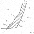
- Fig. 1 shows core materials 3, 4, 6 in cross section of the trailing edge end web 2.
- a first core material 3 has a first specific density in the range of 60 kg / m 3 when using PVC foam and of approx. 100 kg when using PET foam / m 3 , each with a fluctuation range of ⁇ 20 kg / m 3 . Only a part of the first core material 3 is shown. The entire central area, which is determined by the first foam 3, can be in Fig.1 continue upwards and extend to a second foam 4, which borders on the other rotor blade half shell, not shown.
- the specification of the specific density is the specific weight of the foam per cubic meter, i.e. the weight of the foam per cubic meter after it has been foamed, but before the laminate component and thus the foamed first foam 3 have been soaked with resin in the infusion process.
- a strip of the second foam 4 is provided between the rotor blade half-shell 1 and the first foam 3 and has a significantly higher specific density, namely greater than 200 kg / m 3 , preferably greater than 300 kg / m 3 .
- the rear edge end web 2 has a first thickness D in the region of the first foam 3.
- a thickness D of the trailing edge end web 2 preferably initially increases conically, in order then to have a constant second thickness D in the direction of the rotor blade half shell 1, which is preferably greater, however, than the first thickness D.
- the inner bar 5 has a core material made of a third foam 6.
- the third foam 6 is even denser than the first and the second foam 3, 4.
- the inner bar 5 can also consist of a pure epoxy resin bar.
- the inner bar 5 is arranged precisely on the inside of the second foam 4. It extends along the entire longitudinal extent of the trailing edge end web 2, preferably in the area in which the angle between the rotor blade half-shell 1 and the trailing edge end web 2 becomes significantly smaller than 180 °.
- the layers of an inner skin 7 are applied on the inside to the first foam 3, the second foam 4, the inner strip 5 and the semifinished product of the rotor blade half shell 1.
- the inner skin 7 can be fabric and / or jelly layers that contain glass fibers, carbon fibers or other fibers.
- the layers of an outer skin 8 are applied beforehand to the mold half-shell; this can also be tissue and / or gel layers containing glass fibers, carbon fibers or other fibers.
- the rotor blade half-shell 1 is glued together with an associated part of the rear edge end web 2 with a corresponding rotor blade half-shell with an associated part of the rear edge end web 2 to form the rotor blade with the rear edge end web.
- the trailing edge end web 2 has a transition area in the region of the second core material, for example the second foam 4, in which the thickness D of the second core material, for example the second foam 4, differs from the thickness D of the first core material, for example the first foam 3 , increases to the desired, preferably larger thickness D of the second core material.
- the second core material has a region in which the thickness D of the second core material remains essentially constant. The thickness D of the second core material is preferably greater than that of the first core material.
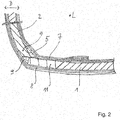
- FIG. 2 Another embodiment of the area between the rotor blade half shell 1 and the trailing edge end web 2 is shown.
- a rear edge belt 11 is arranged directly on the rear edge of the rotor blade and runs in the longitudinal direction L of the rotor blade.
- the rear edge belt 11 is constructed from fabric and / or jelly layers arranged over the entire thickness D of the rotor blade half-shell, which are layered as semi-finished products and soaked in an infusion process with the resin system.
- the rear edge belt preferably has a main fiber direction along the longitudinal direction L of the rotor blade.
- the rear edge belt 11 is significantly more stable than the rest of the sandwich area of the rotor blade half shell 1 in relation to tensile loads in the longitudinal direction L.
- the rear edge end web 2 is then laminated directly onto the rear edge belt 11 as part of the rotor blade half shell 1.
- the trailing edge end web 2 initially has a core material of a standard density in the area spaced apart from the rotor blade half shell 1, while a core material with a higher density is used in an area which adjoins the rotor blade half shell 1. In both cases, they are preferably foams.
- the standard foam has a density of about 60 kg / m 3 ⁇ 20 kg / m 3 when using PVC foam, the high density foam has a density of 200 - 300 kg / m3, preferably even higher densities.
- the rear edge belt 11 can have a somewhat arcuate shape in a cross section perpendicular to the longitudinal direction L and essentially represents a rectangular cross section.
- the rotor blade has, on the one hand, the above-mentioned triangular inner bar 5 from a material with a third specific density, the third specific density preferably being higher than the first and second specific density.
- An outer strip 9 with a triangular cross section is arranged along the outside of the contact line between the trailing edge end web 2 and the rotor blade half shell 1.
- the outer bar 9 has a fourth specific density.
- the rotor blade hub 1 closes at the rear with the rear edge belt 11.
- the outer bar 9 can also be a bar made of a hardened epoxy resin.
- the inner and outer strips 5, 9 are embedded in the semi-finished product of the rotor blade half-shell 1 and the trailing edge end web 2 and coated with the inner skin 7 and the outer skin 8.
- the semi-finished product with the core material of the trailing edge end web 2 and the inner and outer strips 5, 9 is glued to one another to form a laminate and cured.
- the transition point between the trailing edge end web 2 and the rotor blade half-shell 1 is, on the one hand, due to the increasing thickness D of the trailing edge end web 2 at the contact point, on the one hand due to the possibly greater thickness D of the core material of the trailing edge end web 2, and on the other hand also due to the introduction of the inner bar 5 and the outer bar 9 on the other hand, the adhesive connection becomes more stable because the core material has a higher average density than in areas which are further away from the contact point between the trailing edge end web 2 and the rotor blade half shell 1.
Description
- Die Erfindung betrifft ein Rotorblatt für eine Windenergieanlage mit einem Hinterkantenabschlusssteg, der zwischen einer saugseitigen und einer druckseitigen Rotorblatthalbschale angeordnet ist. Die Erfindung betrifft auch ein Verfahren zur Herstellung eines Rotorblattes mit einem Hinterkantenabschlusssteg einer Windenergieanlage.
- Rotorblätter mit Hinterkantenabschlussstegen sind beispielsweise aus der
DE 10 2014 203 936 A1 im Stand der Technik bekannt. Grundsätzlich haben die Hinterkantenabschlussstege die Funktion, die Festigkeit von Rotorblättern im Bereich der Hinterkante zu erhöhen. Hinterkantenabschlussstege werden insbesondere im wurzelnahen Bereich des Rotorblattes vorgesehen. Insbesondere der wurzelnahe Bereich des aerodynamischen Abschnitts des Rotorblattes ist hohen Belastungen ausgesetzt, und damit sind auch die Übergänge zwischen Hinterkantenabschlusssteg und den Rotorblatthalbschalen hohen Belastungen ausgesetzt. - Es ist daher Aufgabe der vorliegenden Erfindung, ein Rotorblatt mit einem Hinterkantenabschlusssteg zur Verfügung zu stellen, das eine höhere Festigkeit im Bereich des Übergangs vom Hinterkantenabschlusssteg zur Rotorblatthalbschale aufweist, und es ist in einem zweiten Aspekt die Aufgabe der Erfindung, ein Verfahren zur Herstellung eines solchen Rotorblattes zur Verfügung zu stellen.
- Die Aufgabe wird in ihrem ersten Aspekt durch ein Rotorblatt mit den Merkmalen des Anspruchs 1 gelöst, bevorzugte Weiterbildungen sind Gegenstand der Unteransprüche.
- Das erfindungsgemäße Rotorblatt zeichnet sich dadurch aus, dass der Hinterkantenabschlusssteg als Laminatbauteil in einer Sandwichbauweise ausgebildet ist, mit einem ersten Kernmaterial, das eine erste spezifische Dichte aufweist, und einem sich entlang eines Übergangsbereiches zwischen Abschlusssteg und Rotorblatthalbschale angeordneten zweiten Kernmaterial, das eine zweite spezifische Dichte aufweist, und die zweite spezifische Dichte ist größer als die erste spezifische Dichte.
- Die Angabe der spezifischen Dichte bezieht sich hier und auch im Folgenden auf das Kernmaterial vor der Laminierung, d. h. bevor dem Kernmaterial ein Harzsystem zugeführt wurde.
- Bei dem ersten und zweiten Kernmaterial handelt es sich insbesondere um erste und zweite Schäume, die während des Laminierverfahrens durch beispielsweise Vakuuminfusion Harzsysteme aufnehmen. Dadurch wird die Dichte des Verbundes aus Harzsystem und Schaum natürlich größer als die spezifische Dichte des aufgeschäumten Schaumes allein.
- Die Erfindung macht von der Idee Gebrauch, die Sandwichbauweise für den Hinterkantenabschlusssteg beizubehalten. Bei der Sandwichbauweise sind eine Innen- und eine Außenhaut vorgesehen, die eine oder mehrere Gewebe- und/oder Gelegelagen aufweisen können. Zwischen der Innen- und der Außenhaut ist das Kernmaterial, aufweisend vorzugsweise bestehend aus z. B. synthetischen Schäumen, Balsaholz oder wabenförmigen Material, angeordnet, das als ein sich über die gesamte Dicke zwischen der Innen- und Außenhaut des Hinterkantenabschlussstegs erstreckender, homogener Schaum ausgebildet sein kann. Es ist jedoch auch denkbar, dass das Kernmaterial entlang der Höhe des Abschlusssteges variiert und unterschiedliche Kernmaterialien verwendet werden.
- Erfindungsgemäß variiert das Kernmaterial hinsichtlich seiner spezifischen Dichte entlang der Höhe des Abschlussstegs, indem die zweite spezifische Dichte eines zweiten Schaumes, der entlang des Übergangsbereiches zwischen Hinterkantenabschlusssteg und Rotorblatthalbschale vorgesehen ist, größer gewählt ist als die erste spezifische Dichte eines ersten Schaumes. Vorzugsweise ist entlang des gesamten Übergangsbereiches in Längsrichtung des Rotorblattes zwischen Hinterkantenabschlusssteg und Rotorblatthalbschale das zweite Kernmaterial vorgesehen. Auch das zweite Kernmaterial ist Bestandteil des Kernmaterials des Hinterkantenabschlussstegs, es berührt daher im Sandwich das erste Kernmaterial, und es berührt die Rotorblatthalbschale, insbesondere ein Kernmaterial, Gelegelagen oder einen Hinterkantengurt der Rotorblatthalbschale.
- Unter Rotorblatthalbschale ist hier die saugseitige und/oder die druckseitige Rotorblatthalbschale eines Rotorblattes zu verstehen. Dabei ist es nicht notwendig, dass die beiden Rotorblatthalbschalen entweder mit oder ohne einen Teil des Hinterkantenabschlussstegs in jeweils einem separaten Laminierverfahren hergestellt werden. Es ist auch denkbar, dass die Rotorblattschale in einem Querschnitt senkrecht zur Längsrichtung, zumindest in Längsrichtung abschnittsweise einstückig hergestellt wird und entlang der Nase der Rotorblattschale keine in Längsrichtung verlaufende Klebelinie vorhanden ist.
- Es ist jedoch bevorzugt vorgesehen, dass die Rotorblatthalbschalen mit Teilen des Abschlusssteges in jeweils separaten Laminierverfahren zunächst einzeln hergestellt werden und anschließend zusammengeklebt werden.
- Die Verwendung von Kernmaterialien unterschiedlicher spezifischer Dichte entlang der Höhe des Hinterkantenabschlussstegs erhöht die Festigkeit des Rotorblattes im Übergangsbereich zwischen Hinterkantenabschlusssteg und Rotorblatthalbschale beträchtlich.
- Vorzugsweise hat die zweite spezifische Dichte einen Wert von größer als 200 kg/m3, besonders bevorzugt hat sie einen Wert von größer als 300 kg/m3.
- Die erste spezifische Dichte liegt bei der Verwendung von PVC-Schaum günstigerweise bei einem Wert von 60 kg/m3, bei der Verwendung von PET-Schaum bei ca. 100 kg/m3, wobei in beiden Fällen Toleranzen von ± 20 kg/m3 oder auch noch größere Toleranzen mitumfasst sind.
- Durch den großen Unterschied in den spezifischen Dichten bleibt das Rotorblatt zum einen noch relativ kostengünstig herstellbar, da Schäume mit geringer spezifischer Dichte grundsätzlich billiger in der Anschaffung sind als Schäume mit hoher spezifischer Dichte. Dennoch ist die Festigkeit erhöht, da gerade in dem stark beanspruchten Übergangsbereich der stabilere Schaum mit der zweiten spezifischen Dichte vorgesehen ist.
- Vorzugsweise bestehen das erste und/oder das zweite Kernmaterial aus Schäumen, da Schäume leicht und einfach als Kernmaterial einer Sandwichbauweise verarbeitet werden können.
- Vorzugsweise ist zusätzlich vorgesehen, dass die Dicke des Hinterkantenabschlussstegs von einem mittleren Bereich, in dem sich das erste Kernmaterial befindet, in einen Übergangsbereich, in dem sich das zweite Kernmaterial befindet, vorzugsweise stetig zunimmt. Durch die dickere Ausführung des Hinterkantenabschlussstegs im Übergangsbereich wird weitere Festigkeit erzielt.
- In einer besonders bevorzugten Ausführungsform der Erfindung ist an einer Innenseite des Rotorblattes entlang des Übergangsbereiches zwischen Rotorblatthalbschale und Hinterkantenabschlusssteg mindestens bereichsweise eine Innenleiste mit einem dritten Kernmaterial mit einer dritten spezifischen Dichte vorgesehen, die mit der Rotorblatthalbschale und dem Hinterkantenabschlusssteg zusammenlaminiert ist. Die Innenleiste wird insbesondere in dem Bereich des Hinterkantenabschlussstegs angebracht, in dem der Winkel zwischen dem Hinterkantenabschlusssteg und der Rotorblatthalbschale zwischen 130° und 90° liegt. Es hat sich gezeigt, dass durch Aufbringung einer im Querschnitt vorzugsweise in etwa dreieckförmigen, leistenartigen Schicht direkt an der Kontaktlinie zwischen Rotorblatthalbschale und Hinterkantenabschlusssteg die Festigkeit des Übergangsbereiches noch einmal erhöht wird, insbesondere wenn die Innenleiste aus einem dritten Kernmaterial mit einer dritten spezifischen Dichte besteht, die einen gleichen oder vorzugsweise höheren Wert als die zweite spezifische Dichte aufweist. Das Kernmaterial der Innenleiste kann ebenfalls ein Schaum mit einer besonders hohen spezifischen Dichte sein, es kann sich jedoch auch um eine bereits im Wesentlichen ausgehärtete oder vorgehärtete Epoxidharzleiste handeln, die vor dem Laminiervorgang innen in die Rotorblatthalbschale eingelegt wird.
- Es ist zweckmäßigerweise vorgesehen, zusätzlich oder anstatt der Innenleiste an einer Außenseite des Rotorblattes entlang des Übergangsbereiches, vorzugsweise direkt an einer Kontaktlinie zwischen Rotorblatthalbschale und Hinterkantenabschlusssteg, eine Außenleiste mit einer vierten spezifischen Dichte anzuordnen, wobei die vierte spezifische Dichte vorzugsweise höher als die erste, zweite und dritte spezifische Dichte ist. Insbesondere die Außenleiste kann aus einer ausgehärteten oder vorgehärteten Epoxidharzleiste bestehen, die in eine sich beim Aufeinandertreffen des Kernmaterials und der Rotorblattaußenhaut ausbildende, im Querschnitt zur Längsrichtung dreiecksförmige Aussparung angepasst ist.
- Die Innen- und/oder Außenleisten werden zusammen mit dem Kernmaterial des Hinterkantenabschlussstegs und dem Kernmaterial der Rotorblatthalbschale mit einer gemeinsamen Innen- bzw. Außenhaut überzogen.
- Insbesondere der zusätzliche Einbau von Innen- und Außenleisten erzeugt eine nochmals erhöhte Festigkeit des Rotorblattes.
- Die Erfindung wird in ihrem zweiten Aspekt durch ein Verfahren mit den Merkmalen des Anspruchs 9 gelöst, indem in einem sich vorzugsweise entlang einer Rotorblatthalbschalenhinterkante erstreckenden Übergangsbereich zwischen Hinterkantenabschlusssteg und Rotorblatthalbschale ein zweites Kernmaterial mit einer zweiten spezifischen Dichte angeordnet wird und entlang des zweiten Kernmaterials auf einer der Rotorblatthalbschale gegenüberliegenden Seite ein erstes Kernmaterial mit einer ersten spezifischen Dichte angeordnet wird und die zweite spezifische Dichte größer als die erste spezifische Dichte gewählt wird und das erste und das zweite Kernmaterial mit einem Harzsystem infundiert werden.
- In dem Verfahren wird nicht notwendigerweise der komplette Hinterkantenabschlusssteg in einem Stück gefertigt, sondern es kann ein Teil des Hinterkantenabschlussstegs an jeder der beiden Rotorblatthalbschalen gefertigt werden.
- Vorzugsweise werden die Rotorblatthalbschalen separat gefertigt und eine saug- und eine druckseitige Rotorblatthalbschale mit Hinterkantenabschlusssteg miteinander verbunden. Es ist jedoch auch denkbar, dass die Rotorblattschale einstückig oder zumindest in Längsrichtung gesehen abschnittsweise einstückig oder als nasenseitige Halbschale und hinterkantenseitige Halbschale gefertigt wird.
- Vorzugsweise werden separat gefertigte saug- und druckseitige Rotorblatthalbschalen mit einem Hinterkantenabschlusssteg miteinander verbunden.
- Zweckmäßigerweise werden zunächst in eine Formhalbschale Außenlagen und Innenlagen, das erste und zweite Kernmaterial des Hinterkantenabschlussstegs sowie die Innenleiste gelegt. Dadurch wird insbesondere der Übergangsbereich durch eine durchgehende Innen- und Außenhaut stabilisiert.
- Der Hinterkantenabschlusssteg wird günstigerweise in einer Sandwichbauweise gefertigt. Ebenso kann die Rotorblatthalbschale in einer Sandwichbauweise gefertigt sein, wobei das Kernmaterial der Rotorblatthalbschale ebenfalls aus einem Schaum oder mehreren Schäumen bestehen kann. Es ist jedoch auch denkbar, dass die Rotorblatthalbschale entlang ihrer Dicke vollständig aus Gewebe- und/oder Gelegelagen aufgebaut ist. Vorzugsweise ist jedoch vorgesehen, dass entlang der Hinterkante der Rotorblatthalbschale ein Hinterkantengurt verläuft, der eine höhere Festigkeit, insbesondere Zugfestigkeit in Längsrichtung aufweist und die Biegesteifigkeit und auch die Beulsteifigkeit des Rotorblattes dadurch erhöht werden.
- Der Hinterkantengurt kann als separates Bauteil vorgefertigt und dann in die Rotorblatthalbschale eingefügt werden, es ist jedoch auch denkbar, die Halbzeuge, aus denen der Hinterkantengurt besteht, zusammen mit den Halbzeugen, aus denen die Rotorblatthalbschale und der Hinterkantenabschlusssteg bestehen, in die Formhalbschale einzulegen und in einem gemeinsamen Infusionsprozess mit der Harzmatrix zu tränken. Es ist ebenfalls möglich, die Rotorblatthalbschale und/oder den Hinterkantenabschlusssteg ganz oder bereichsweise als Preform auszuführen und zusammen mit den übrigen Halbzeugen in die Formhalbschale einzulegen.
- Eine Preform besteht aus trockenen Faserlagen und optional zusätzlichem Kernmaterial, wobei die Faserlagen und das Kernmaterial miteinander durch einen Klebstoff lösbar miteinander verbunden sind, wobei eine anschließende Infusion der Harzmatrix möglich ist.
- In einer besonders bevorzugten Ausführungsform des erfindungsgemäßen Verfahrens wird entlang der Rotorblatthalbschalenhinterkante und unmittelbar auf das zweite Kernmaterial und unmittelbar auf die Rotorblatthalbschalenhinterkante ein drittes Kernmaterial angeordnet, dessen spezifische Dichte vorzugsweise einen höheren Wert hat als den der ersten und zweiten spezifischen Dichte. Um den Übergang zwischen Rotorblatthalbschale und Hinterkantenabschlusssteg zusätzlich zu stabilisieren, wird vorzugsweise innen auf die direkte Kontaktlinie zwischen Hinterkantenabschlusssteg und Rotorblatthalbschale das dritte Kernmaterial angeordnet; das dritte Kernmaterial ist in das Laminat des Rotorblattes integriert und wird innenseitig von der Innenhaut des Rotorblattes mitüberzogen und erhöht durch seine Anordnung die Festigkeit im Übergangsbereich zwischen Rotorblatthalbschale und Hinterkantenabschlusssteg.
- In entsprechender Weise kann in einer weiteren bevorzugten Ausführungsform des erfindungsgemäßen Verfahrens zusätzlich oder stattdessen auch außen entlang der Rotorblatthinterkante und unmittelbar auf das zweite Kernmaterial und auf die Rotorblatthalbschalenhinterkante ein viertes Kernmaterial angeordnet werden. Die spezifische Dichte des vierten Kernmaterials hat vorzugsweise einen noch höheren Wert als den der ersten, zweiten und auch dritten spezifischen Dichte.
- Insbesondere an der Außenseite des Übergangsbereiches wirken hohe Belastungen auf die Rotorblattschale, sodass durch die Verwendung einer besonders hohen Dichte eine besondere Festigkeit erzielt wird. Es ist vorzugsweise vorgesehen, dass das vierte Kernmaterial aus einer Epoxidharzleiste besteht, die passgenau in eine dreieckige Aussparung zwischen zweitem Kernmaterial und Rotorblatthinterkante eingepasst wird.
- Das dritte und das vierte Kernmaterial können sich über die gesamte Längsausdehnung des Übergangsbereichs zwischen Rotorblatthalbschale und Hinterkantenabschlusssteg erstrecken.
- Vorzugsweise wird das vierte Kernmaterial entlang eines Hinterkantengurtes angeordnet und günstigerweise wird das vierte Kernmaterial entlang seiner Erstreckung den Hinterkantengurt berührend angeordnet.
- Die Erfindung wird anhand von zwei Ausführungsbeispielen in zwei Figuren beschrieben. Dabei zeigen:
- Fig. 1
- Schnittansicht eines Bereichs einer Rotorblattschale im Bereich zwischen einer Rotorblatthalbschale und einem Hinterkantenabschlusssteg in einer ersten Ausführungsform,
- Fig. 2
- Schnittansicht eines Bereichs der Rotorblattschale im Bereich zwischen der Rotorblatthalbschale und dem Hinterkantenabschlusssteg in einer zweiten Ausführungsform.
- Die erfindungsgemäßen Rotorblätter werden vorzugsweise im Wesentlichen aus zwei Rotorblatthalbschalen, die separat vorgefertigt werden, zusammengesetzt. Allerdings können auch zusätzliche Bauteile, wie Hauptgurte und Hauptstege oder ähnliche zusätzlich in den Innenraum des Rotorblattes eingebaut werden. Auch diese können als separate Bauteile zur Verfügung gestellt werden.
- Erfindungsgemäß wird die saug- bzw. druckseitige Rotorblatthalbschale 1 jeweils zusammen mit einem Abschnitt eines Hinterkantenabschlussstegs 2 jeweils einteilig vorgefertigt.
- Rotorblätter können in einem Querschnitt senkrecht zu ihrer Längsrichtung L nicht nur eine schmal zulaufende Hinterkante aufweisen, sondern in anderen Ausführungsformen von Rotorblättern auch durch einen Hinterkantenabschlusssteg 2 gleichsam abgeschnitten sein. Der Hinterkantenabschlusssteg 2 beginnt dabei in Längsrichtung L des Rotorblattes vorzugsweise am wurzelseitigen Ende des Rotorblattes, er kann aber auch in einem Abstand dazu beginnen und erstreckt sich vorzugsweise bis in den Bereich zwischen 30 % und 50 % der Rotorblattlänge.
- Der Hinterkantenabschlusssteg 2 schließt einen Innenraum des Rotorblattes zur Hinterkante hin vorzugsweise vollständig ab.
- Eine Höhe des Hinterkantenabschlussstegs 2 ist über die Länge des Rotorblattes variabel. Die separaten Bauteile werden in für sie individuell bestimmten Herstellungsformen gefertigt. In die Herstellungsform werden zunächst mehrere Schichten, beispielsweise faserhaltige Gewebelagen, faserhaltige Gelegelagen, Schäume, Balsa usw., übereinander- und/oder nebeneinandergelegt. Die so angeordneten Schichten bilden ein vorzugsweise trockenes Halbzeug aus. Das Halbzeug wird in Verfahren, wie beispielsweise Resin Injection Moulding (RIM-Verfahren) oder Resin Transfer Moulding (RTM-Verfahren), mit einem Harzsystem infundiert. Das Harzsystem härtet in einer zunächst exothermen chemischen Reaktion und anschließender Wärmezufuhr innerhalb des Halbzeugs aus. Dem harzgetränkten Halbzeug wird, nachdem es in der exothermen Reaktion einen sogenannten exothermen Peak durchschritten hat, extern Wärme zugeführt, um es auf einer geeigneten Prozesstemperatur zu halten. Auf der Prozesstemperatur härtet das Harzsystem dann vollständig aus und vernetzt.
- Üblicherweise werden die Halbzeuge zum Bau der Rotorblatthalbschale in der vorgegebenen Schichtung auf den Innenseiten von Formhalbschalen positioniert und nach der vollständigen Schichtung mit einer Vakuumfolie an Rändern der Formhalbschale abgedichtet. Die Vakuumfolie und/oder Formhalbschale weist mehrere Zuführungen und Abführungen auf, durch die das flüssige Harzsystem in das Halbzeug hineingesogen werden kann. Bei dem Harzsystem handelt es sich vorzugsweise um ein Duroplast-Harzsystem wie Epoxidharze, Polyesterharze, Vinylesterharze oder Polyurethanharze.
- Üblicherweise werden die Bauteile als Laminatbauteile in einer Sandwichbauweise gefertigt und zur Verfügung gestellt. Unter einer Sandwichbauweise wird hier eine Bauweise eines Bauteils verstanden, das in einem Querschnitt ein Innenlaminat und ein Außenlaminat aufweist, die die Innenhaut bzw. die Außenhaut nach der Aushärtung ausbilden. Bei dem Innen- und Außenlaminat handelt es sich üblicherweise um mit einem Harzsystem getränkte Gewebe- und/oder Gelegelagen aus Glasfasern, Kohlenstofffasern oder anderen Fasern.
- Zwischen der Innen- und Außenhaut ist ein Sandwichkern vorgesehen, der aus einem synthetischen Schaum oder Balsaholz besteht und hier in einer bevorzugten Ausführung einen synthetischen Schaum aufweist. Dabei kann ein Sandwichkern unterschiedliche Schaumarten umfassen und bereichsweise aus unterschiedlichen Schaumarten ausgebildet sein. Bei den Schäumen kann es sich um PVC-, SAN- oder Polyurethan-Schäume, die Anteile von Balsaholz aufweisen können, handeln. Es kann sich aber auch um Schäume wie Polystyrol, beispielsweise Compaxx 90 der Firma Dow Chemical handeln.
- Erfindungswesentlich ist an der Konstruktion, dass im Hinterkantenabschlusssteg 2 verwendeter zweiter Schaum 4 im Bereich des Überganges zur Rotorblatthalbschale 1 eine höhere Dichte aufweist als erster Schaum 3 in einem entlang einer Höhe H gesehen mittleren Bereich des Hinterkantenabschlussstegs 2. Der zweite Schaum 4 zieht sich entlang des Kontaktbereichs zwischen Hinterkantenabschlusssteg 2 und Rotorblatthalbschale 1.
-
Fig. 1 zeigt Kernmaterialien 3, 4, 6 im Querschnitt des Hinterkantenabschlussstegs 2. ein erstes Kernmaterial 3 weist bei der Verwendung von PVC-Schaum eine erste spezifische Dichte im Bereich von 60 kg/m3 und bei der Verwendung von PET-Schaum von ca. 100 kg/m3, jeweils mit einer Schwankungsbreite von ± 20 kg/m3, auf. Von dem ersten Kernmaterial 3 ist nur ein Teil dargestellt. Der gesamte mittlere Bereich, der durch den ersten Schaum 3 bestimmt ist, kann sich inFig.1 nach oben hin weiter fortsetzen und sich bis zu einem zweiten Schaum 4, der an die andere, nicht dargestellte Rotorblatthalbschale grenzt, erstrecken. - Bei der Angabe der spezifischen Dichte handelt es sich um das spezifische Gewicht des Schaumes pro Kubikmeter, also das Gewicht des Schaumes pro Kubikmeter nach dessen Aufschäumen, aber bevor das Laminatbauteil und damit der aufgeschäumte erste Schaum 3 im Infusionsverfahren mit Harz getränkt wurden.
- Zwischen der Rotorblatthalbschale 1 und dem ersten Schaum 3 ist ein Streifen des zweiten Schaums 4 vorgesehen, der eine deutlich höhere spezifische Dichte, nämlich von größer als 200 kg/m3, vorzugsweise größer als 300 kg/m3 aufweist. Auch hier bezieht sich die Angabe der spezifischen Dichte auf den aufgeschäumten Schaum vor der Harzinfusion. Der Hinterkantenabschlusssteg 2 weist im Bereich des ersten Schaumes 3 eine erste Dicke D auf. In Richtung der Rotorblatthalbschale 1, d. h. in
Fig. 1 in Richtung des unteren Endes derFig. 1 , nimmt eine Dicke D des Hinterkantenabschlussstegs 2 vorzugsweise zunächst konisch zu, um dann ein Stück weit in Richtung der Rotorblatthalbschale 1 eine gleichbleibende zweite Dicke D aufzuweisen, die vorzugsweise aber größer als die erste Dicke D ist. - In einem Streifen entlang des zweiten hochdichten Schaums 4 ist eine im Querschnitt dreiecksförmige Innenleiste 5, den zweiten Schaum 4 mit der Rotorblatthalbschale 1 verbindend, vorgesehen. Die Innenleiste 5 weist ein Kernmaterial aus einem dritten Schaum 6 auf. Der dritte Schaum 6 ist noch dichter als der erste und der zweite Schaum 3, 4. Die Innenleiste 5 kann aber auch aus einer reinen Epoxidharzleiste bestehen. Die Innenleiste 5 ist passgenau auf die Innenseite des zweiten Schaumes 4 angeordnet. Sie erstreckt sich entlang der gesamten Längsausdehnung des Hinterkantenabschlussstegs 2 vorzugsweise in dem Bereich, in dem der Winkel zwischen der Rotorblatthalbschale 1 und dem Hinterkantenabschlusssteg 2 deutlich kleiner als 180° wird.
- Innenseitig auf den ersten Schaum 3, den zweiten Schaum 4, die Innenleiste 5 sowie das Halbzeug der Rotorblatthalbschale 1 sind die Lagen einer Innenhaut 7 aufgebracht. Bei der Innenhaut 7 kann es sich um Gewebe- und/oder Gelegelagen, die Glasfasern, Kohlenstoffasern oder andere Fasern enthalten, handeln. Vorab werden auf die Formhalbschale die Lagen einer Außenhaut 8 aufgebracht; auch dabei kann es sich um Gewebe- und/oder Gelegelagen, die Glasfasern, Kohlenstoffasern oder andere Fasern enthalten, handeln. Nach Anordnung des Halbzeugs einschließlich Außen- und Innenhaut 8, 7 auf der Innenseite der Formhalbschale, wird die Anordnung innenseitig mit einer Vakuumfolie abgedichtet und mit einem Harzsystem, wie eingangs genannt, infundiert. Nach Aushärten des Bauteils wird die Rotorblatthalbschale 1 mit einem ihr zugeordneten Teil des Hinterkantenabschlussstegs 2 mit einer korrespondierenden Rotorblatthalbschale mit einem ihr zugeordneten korrespondierenden Teil des Hinterkantenabschlussstegs 2 zum Rotorblatt mit dem Hinterkantenabschlusssteg zusammengeklebt.
- Zum einen weist der Hinterkantenabschlusssteg 2 im Bereich des zweiten Kernmaterials, beispielsweise des zweiten Schaums 4, einen Übergangsbereich auf, in dem die Dicke D des zweiten Kernmaterials, beispielsweise des zweiten Schaums 4, von der Dicke D des ersten Kernmaterials, beispielsweise des ersten Schaumes 3, auf die gewünschte, vorzugsweise größere Dicke D des zweiten Kernmaterials ansteigt. Das zweite Kernmaterial weist einen Bereich auf, in dem die Dicke D des zweiten Kernmaterials im Wesentlichen konstant bleibt. Die Dicke D des zweiten Kernmaterials ist vorzugsweise höher als diejenige des ersten Kernmaterials.
- Durch die zur Rotorblatthalbschale 1 hin zunehmende Dicke D des Hinterkantenabschlussstegs 2 können die an den Übergangsstellen zwischen Rotorblatthalbschale 1 und Hinterkantenabschlusssteg 2 auftretenden sehr hohen Belastungen besser aufgenommen werden, und es kann eine Konstruktion mit besonders hoher Festigkeit, insbesondere gegenüber Biegebelastungen, zur Verfügung gestellt werden. Diesem Ziel dient auch der Einsatz des hochdichten Kernmaterials in diesem Bereich.
- In
Fig. 2 ist eine andere Ausführungsform des Bereichs zwischen Rotorblatthalbschale 1 und Hinterkantenabschlusssteg 2 dargestellt. Dabei ist auch der Aufbau der Rotorblatthalbschale 1 dargestellt, die in einer Sandwichbauweise hergestellt ist, wobei der Sandwichkern aus einem Kernmaterial mit einem synthetischen Schaum besteht, der bei der Verwendung von PVC-Schaum günstigerweise ebenfalls eine Dichte von etwa 60 kg/m3 ± 20 kg/m3 aufweist, bzw. aus Balsaholz. - Direkt an der Rotorblatthinterkante ist ein Hinterkantengurt 11 in Längsrichtung L des Rotorblattes verlaufend angeordnet. Der Hinterkantengurt 11 ist aus über die gesamte Dicke D der Rotorblatthalbschale angeordneten Gewebe- und/oder Gelegelagen konstruiert, die als Halbzeug übereinandergeschichtet werden und in einem Infusionsverfahren mit dem Harzsystem getränkt werden. Der Hinterkantengurt weist vorzugsweise eine Hauptfaserrichtung entlang der Längsrichtung L des Rotorblattes auf. Der Hinterkantengurt 11 ist gegenüber Zugbelastungen in Längsrichtung L deutlich stabiler als der übrige Sandwichbereich der Rotorblatthalbschale 1. Direkt am Hinterkantengurt 11 als Teil der Rotorblatthalbschale 1 anschließend ist der Hinterkantenabschlusssteg 2 anlaminiert. Der Hinterkantenabschlusssteg 2 weist, wie in der erstgenannten Ausführungsform, zunächst im Bereich beabstandet von der Rotorblatthalbschale 1, ein Kernmaterial einer Standarddichte auf, während in einem Bereich, der sich der Rotorblatthalbschale 1 anschließt, ein Kernmaterial mit einer höheren Dichte verwendet wird. In beiden Fällen handelt es sich vorzugsweise um Schäume. Der Standardschaum weist bei der Verwendung von PVC-Schaum eine Dichte von etwa 60 kg/m3 ± 20 kg/m3 auf, der hochdichte Schaum eine Dichte von 200 - 300 kg/m3, vorzugweise sogar höhere Dichten auf.
- Der Hinterkantengurt 11 kann in einem Querschnitt senkrecht zur Längsrichtung L etwas bogenförmig nach außen ausgeformt sein und stellt im Wesentlichen einen rechteckigen Querschnitt dar.
- An dem Kontaktbereich zwischen Hinterkantenabschlusssteg 2 und Rotorblatthalbschale 1 weist das Rotorblatt zum einen die oben genannte im Querschnitt dreiecksförmige Innenleiste 5 aus einem Material mit einer dritten spezifischen Dichte auf, wobei die dritte spezifische Dichte vorzugsweise höher als die erste und zweite spezifische Dichte ist.
- Eine im Querschnitt dreiecksförmige Außenleiste 9 ist entlang der Außenseite der Kontaktlinie zwischen Hinterkantenabschlusssteg 2 und Rotorblatthalbschale 1 angeordnet. Die Außenleiste 9 weist eine vierte spezifische Dichte auf. Die Rotorblatthabschale 1 schließt hinten mit dem Hinterkantengurt 11 ab. Bei der Außenleiste 9 kann es sich ebenfalls um eine Leiste aus einem ausgehärteten Epoxidharz handeln. Die Innen- und Außenleiste 5, 9 werden vor dem Infusionsvorgang formschlüssig in das Halbzeug der Rotorblatthalbschale 1 und des Hinterkantenabschlussstegs 2 eingebettet und mit der Innenhaut 7 und der Außenhaut 8 beschichtet. Durch das Infusionsverfahren wird das Halbzeug mit dem Kernmaterial des Hinterkantenabschlussstegs 2 und den Innen- und Außenleisten 5, 9 miteinander zu einem Laminat verklebt und ausgehärtet. Die Übergangsstelle zwischen Hinterkantenabschlusssteg 2 und Rotorblatthalbschale 1 ist zum einen durch die an der Kontaktstelle größer werdende Dicke D des Hinterkantenabschlussstegs 2 aufgrund der zum einen möglicherweise größeren Dicke D des Kernmaterials des Hinterkantenabschlussstegs 2, zum anderen auch aufgrund des Einbringens der Innenleiste 5 und der Außenleiste 9 stabiler, zum anderen wird die Klebverbindung stabiler, weil das Kernmaterial eine höhere durchschnittliche Dichte aufweist, als in Bereichen, die von der Kontaktstelle zwischen Hinterkantenabschlusssteg 2 und Rotorblatthalbschale 1 weiter entfernt sind.
-
- 1
- Rotorblatthalbschale
- 2
- Hinterkantenabschlusssteg
- 3
- erster Schaum
- 4
- zweiter Schaum
- 5
- Innenleiste
- 6
- dritter Schaum
- 7
- Innenhaut
- 8
- Außenhaut
- 9
- Außenleiste
- 11
- Hinterkantengurt
- L
- Längsrichtung
- D
- Dicke
- H
- Höhe
Claims (15)
- Rotorblatt für eine Windenergieanlage mit einem Hinterkantenabschlusssteg (2) der zwischen einer saugseitigen und einer druckseitigen Rotorblatthalbschale (1) angeordnet ist,
dadurch gekennzeichnet, dass der Hinterkantenabschlusssteg (2) als Laminatbauteil in einer Sandwichbauweise ausgebildet ist mit einem ersten Kernmaterial (3), das eine erste spezifischen Dichte aufweist und einem sich entlang eines Übergangsbereichs zwischen dem Hinterkantenabschlusssteg (2) und der Rotorblatthalbschale (1) angeordneten zweiten Kernmaterial (4), das eine zweite spezifische Dichte aufweist, und die zweite spezifische Dichte ist größer als die erste spezifische Dichte. - Rotorblatt nach Anspruch 1,
dadurch gekennzeichnet, dass die zweite spezifische Dichte einen Wert größer als 200 kg/m3 hat. - Rotorblatt nach Anspruch 2,
dadurch gekennzeichnet, dass die zweite spezifische Dichte einen Wert von größer als 300 kg/m3 hat. - Rotorblatt nach Anspruch 1, 2 oder 3,
dadurch gekennzeichnet, dass die erste spezifische Dichte einen Wert von 60 kg/m3 ±20kg/m3 hat, wenn ein PET-Schaum eingesetzt wird, und wenn ein PVC Schaum eingesetzt wird, einen Wert von 100 kg/m3 ±20kg/m3. - Rotorblatt nach einem der vorstehenden Ansprüche,
dadurch gekennzeichnet, dass an einer Innenseite des Rotorblattes entlang des Übergangsbereiches zwischen der Rotorblatthalbschale (1) und dem Hinterkantenabschlusssteg (2) eine Innenleiste (5) mit einem dritten Kernmaterial (6) mit einer dritten spezifischen Dichte verläuft, die mit der Rotorblatthalbschale (1) und dem Hinterkantenabschlusssteg (2) zusammenlaminiert ist. - Rotorblatt nach Anspruch 5,
dadurch gekennzeichnet, dass die dritte spezifische Dichte vor der Laminierung einen gleichen oder höheren Wert als die zweite spezifische Dichte aufweist. - Rotorblatt nach einem der vorstehenden Ansprüche,
dadurch gekennzeichnet, dass an einer Außenseite des Rotorblattes entlang des Übergangsbereiches eine Außenleiste (9) mit einer vierten spezifischen Dichte angeordnet ist, die höher als die erste, zweite und dritte spezifische Dichte ist. - Rotorblatt nach Anspruch 7,
dadurch gekennzeichnet, dass entlang der Hinterkanten beider Rotorblatthalbschalen (1) ein Hinterkantengurt (11) verläuft und das zweite Kernmaterial (4) und /oder das dritte Kernmaterial (6) unmittelbaren Kontakt mit dem Hinterkantengurt (11) aufweisen. - Verfahren zur Herstellung eines Rotorblattes mit einem Hinterkantenabschlusssteg (2) einer Windenergieanlage, indem
in einem sich entlang einer Rotorblatthalbschalenhinterkante erstreckenden Übergangsbereich zwischen dem Hinterkantenabschlusssteg (2) und einer Rotorblatthalbschale (1) ein zweites Kernmaterial (4) mit einer zweiten spezifischen Dichte angeordnet wird,
entlang des zweiten Kernmaterials (4) auf einer der Rotorblatthalbschale (1) gegenüberliegenden Seite ein erstes Kernmaterial (3) mit einer ersten spezifischen Dichte angeordnet wird und die zweite spezifische Dichte größer als die erste spezifische Dichte gewählt wird. - Verfahren nach Anspruch 9,
dadurch gekennzeichnet, dass die gesamte Anordnung der Halbzeuge in der Rotorblatthalbschale (1) und dem Hinterkantenabschlusssteg (2) inklusive des ersten und zweiten Kernmaterials (3, 4) und einer Innenleiste (5) und einer Außenleiste (9) mit einem Duroplast-Harzsystem infundiert wird. - Verfahren nach Anspruch 9 oder 10,
dadurch gekennzeichnet, dass eine saug- und eine druckseitige Rotorblatthalbschale (1) mit dem Hinterkantenabschlusssteg (2) miteinander verbunden werden. - Verfahren nach Anspruch 10,
dadurch gekennzeichnet, dass in eine Formhalbschale Außenlagen und Innenlagen, das erste und zweite Kernmaterial (3, 4) des Hinterkantenabschlussstegs (2) und die Innenleiste (5) und die Außenleiste (9) gelegt werden. - Verfahren nach einem der Ansprüche 9 bis 12,
dadurch gekennzeichnet, dass innen entlang der Rotorblatthalbschalenhinterkante und unmittelbar auf das zweite Kernmaterial (4) und auf die Rotorblatthalbschalenhinterkante ein drittes Kernmaterial (6) angeordnet wird, dessen spezifische Dichte einen höheren Wert hat als den der ersten und einen gleichen oder höheren Wert hat als den der zweiten spezifischen Dichte. - Verfahren nach den Ansprüchen 10 und 13,
dadurch gekennzeichnet, dass außen entlang der Rotorblatthalbschalenhinterkante und unmittelbar auf das zweite Kernmaterial (4) und auf die Rotorblatthalbschalenhinterkante die Außenleiste (9) angeordnet wird, deren spezifische Dichte einen höheren Wert hat als den der ersten, zweiten und dritten spezifischen Dichte. - Verfahren nach Anspruch 14,
dadurch gekennzeichnet, dass ein viertes Kernmaterial der Außenleiste (9) aus einem Epoxidharz oder einem Polyurethanharz besteht.
Applications Claiming Priority (1)
| Application Number | Priority Date | Filing Date | Title |
|---|---|---|---|
| DE102016011757.5A DE102016011757A1 (de) | 2016-09-22 | 2016-09-22 | Rotorblatt mit Abschlusssteg |
Publications (2)
| Publication Number | Publication Date |
|---|---|
| EP3299613A1 EP3299613A1 (de) | 2018-03-28 |
| EP3299613B1 true EP3299613B1 (de) | 2020-01-08 |
Family
ID=59858647
Family Applications (1)
| Application Number | Title | Priority Date | Filing Date |
|---|---|---|---|
| EP17190853.6A Active EP3299613B1 (de) | 2016-09-22 | 2017-09-13 | Rotorblatt mit abschlusssteg |
Country Status (4)
| Country | Link |
|---|---|
| EP (1) | EP3299613B1 (de) |
| DE (1) | DE102016011757A1 (de) |
| DK (1) | DK3299613T3 (de) |
| ES (1) | ES2781948T3 (de) |
Families Citing this family (4)
| Publication number | Priority date | Publication date | Assignee | Title |
|---|---|---|---|---|
| WO2018015250A1 (en) * | 2016-07-19 | 2018-01-25 | Lm Wind Power International Technology Ii Aps | Wind turbine blade with flatback segment and related method |
| DE102017004058A1 (de) * | 2017-04-27 | 2018-10-31 | Senvion Gmbh | Rotorblatt einer windenergieanlage und verfahren zum herstellen eines solchen, abschlusssteg eines rotorblatts und verwendung eines solchen |
| DE102018005030A1 (de) | 2018-06-26 | 2020-01-02 | Senvion Gmbh | Rotorblatt mit Steg in Wabensandwichbauweise |
| DK3736436T3 (da) * | 2019-05-09 | 2023-01-30 | Siemens Gamesa Renewable Energy As | Rotorvinge til en vindmølle |
Family Cites Families (7)
| Publication number | Priority date | Publication date | Assignee | Title |
|---|---|---|---|---|
| DE3014347C2 (de) * | 1980-04-15 | 1983-05-26 | Messerschmitt-Bölkow-Blohm GmbH, 8000 München | Verfahren zur Herstellung von schaumkerngestützen, faserverstärkten Kunststoff-Formkörpern wie Flügel, Rotorblätter etc. großer Längen-und Breitenausdehnung |
| DE102010038408B4 (de) * | 2010-07-26 | 2020-11-19 | Airbus Operations Gmbh | Strukturelement für ein Luft- und Raumfahrzeug und Verfahren zum Herstellen eines derartigen Strukturelementes |
| DE102011077609B4 (de) * | 2011-06-16 | 2015-01-22 | Senvion Se | Fertigung einer Rotorblattschale |
| DE102011082664C5 (de) * | 2011-09-14 | 2017-08-10 | Senvion Gmbh | Form zur Herstellung eines Steges und Steg für ein Rotorblatt einer Windenergieanlage |
| EP2662204A1 (de) * | 2012-05-07 | 2013-11-13 | Nordex Energy GmbH | Verfahren, vorgefertiges Bauelement und Form zur Herstellung eines Windenergieanlagenbauteils |
| DE102014203936B4 (de) | 2014-03-04 | 2016-03-24 | Senvion Gmbh | Verfahren zum Herstellen eines Rotorblatts einer Windenergieanlage, Rotorblatt und Windenergieanlage |
| CN104696167B (zh) * | 2014-12-24 | 2017-06-20 | 中国科学院工程热物理研究所 | 一种钝尾缘风力涡轮机叶片及其实施装置与方法 |
-
2016
- 2016-09-22 DE DE102016011757.5A patent/DE102016011757A1/de not_active Withdrawn
-
2017
- 2017-09-13 ES ES17190853T patent/ES2781948T3/es active Active
- 2017-09-13 EP EP17190853.6A patent/EP3299613B1/de active Active
- 2017-09-13 DK DK17190853.6T patent/DK3299613T3/da active
Non-Patent Citations (1)
| Title |
|---|
| None * |
Also Published As
| Publication number | Publication date |
|---|---|
| EP3299613A1 (de) | 2018-03-28 |
| ES2781948T3 (es) | 2020-09-09 |
| DK3299613T3 (da) | 2020-04-14 |
| DE102016011757A1 (de) | 2018-03-22 |
Similar Documents
| Publication | Publication Date | Title |
|---|---|---|
| EP2904262B1 (de) | Faserverbundbauteil für das rotorblatt einer windturbine | |
| EP3299613B1 (de) | Rotorblatt mit abschlusssteg | |
| DE102011078951B4 (de) | Verfahren zum Herstellen eines Rotorblatts für eine Windenergieanlage, Sandwich-Preform und Rotorblatt für eine Windenergieanlage | |
| EP3496936B1 (de) | Gurt aus vorgefertigten elementen mit gelege und ein verfahren zu seiner fertigung | |
| EP2567807B1 (de) | Verfahren zur Herstellung eines Windenergieanlagenrotorblattbauteils mit einem vorgefertigten Hauptgurt | |
| EP2363599B1 (de) | Rotorblatt für eine Windenergieanlage, Windenergieanlage und Verfahren zum Herstellen eines Rotorblatts | |
| EP2666615B1 (de) | Verfahren zur Herstellung einer Windenergieanlagenrotorblatthalbschale bzw. eines Windenergieanlagenrotorblatts und Herstellungsform zu diesem Zweck | |
| DE102009039534A1 (de) | Composite-Körper | |
| WO2005011964A1 (de) | Tragstruktur | |
| CH666410A5 (de) | Ski. | |
| EP3018342B1 (de) | Verfahren zum herstellen eines rotorblatts einer windenergieanlage | |
| EP2561977B1 (de) | Verfahren zur Herstellung eines Windenergieanlagenrotorblattteils mit einem kohlenstofffaserverstärkten Hauptgurt | |
| EP2670581B1 (de) | Verfahren, halbzeug für die herstellung eines faserverstärkten bauteils einer windenergieanlage und verwendung des halbzeuges | |
| DE102015007289A1 (de) | Rotorblatt, Rotorblattgurt und Verfahren zum Herstellen eines Rotorblattgurts | |
| EP3260697A1 (de) | Hinterkantengurt mit rechteckquerschnitt | |
| DE102005030939A1 (de) | Verfahren zur Herstellung eines im Wesentlichen schalenförmigen Bauteils | |
| EP3535115B1 (de) | Rotorblatt mit gekrümmten pultrudaten und verfahren zur herstellung des selben | |
| EP2890552B1 (de) | Verfahren zur fertigung eines rotorblattes und ein rotorblatt einer windenergieanlage | |
| EP3486476B1 (de) | Steg für ein rotorblatt einer windenergieanlage und verfahren zum herstellen eines stegs | |
| EP3551438B1 (de) | Hinterkantengurt eines rotorblatts einer windenergieanlage, rotorblatt und verfahren zum herstellen eines hinterkantengurts | |
| EP3482918A1 (de) | Verfahren zur herstellung eines stegs für ein windenergieanlagenrotorblatt | |
| DE102021105792A1 (de) | Sandwichbauteil, Turbinen-Strahltriebwerk und Verfahren zu dessen Herstellung | |
| EP3015702A1 (de) | Rotorblatt für eine windkraftanlage und verfahren zum herstellen eines rotorblatts | |
| EP3587801A1 (de) | Rotorblatt mit steg in wabensandwichbauweise | |
| DE102022115553A1 (de) | Verfahren zur Herstellung eines Faserverbundbauteils und Faserverbund-Hohlbauteils sowie Windkraftanlage hierzu |
Legal Events
| Date | Code | Title | Description |
|---|---|---|---|
| PUAI | Public reference made under article 153(3) epc to a published international application that has entered the european phase |
Free format text: ORIGINAL CODE: 0009012 |
|
| STAA | Information on the status of an ep patent application or granted ep patent |
Free format text: STATUS: THE APPLICATION HAS BEEN PUBLISHED |
|
| AK | Designated contracting states |
Kind code of ref document: A1 Designated state(s): AL AT BE BG CH CY CZ DE DK EE ES FI FR GB GR HR HU IE IS IT LI LT LU LV MC MK MT NL NO PL PT RO RS SE SI SK SM TR |
|
| AX | Request for extension of the european patent |
Extension state: BA ME |
|
| STAA | Information on the status of an ep patent application or granted ep patent |
Free format text: STATUS: REQUEST FOR EXAMINATION WAS MADE |
|
| 17P | Request for examination filed |
Effective date: 20180827 |
|
| RBV | Designated contracting states (corrected) |
Designated state(s): AL AT BE BG CH CY CZ DE DK EE ES FI FR GB GR HR HU IE IS IT LI LT LU LV MC MK MT NL NO PL PT RO RS SE SI SK SM TR |
|
| GRAP | Despatch of communication of intention to grant a patent |
Free format text: ORIGINAL CODE: EPIDOSNIGR1 |
|
| STAA | Information on the status of an ep patent application or granted ep patent |
Free format text: STATUS: GRANT OF PATENT IS INTENDED |
|
| INTG | Intention to grant announced |
Effective date: 20190212 |
|
| GRAS | Grant fee paid |
Free format text: ORIGINAL CODE: EPIDOSNIGR3 |
|
| GRAJ | Information related to disapproval of communication of intention to grant by the applicant or resumption of examination proceedings by the epo deleted |
Free format text: ORIGINAL CODE: EPIDOSDIGR1 |
|
| GRAL | Information related to payment of fee for publishing/printing deleted |
Free format text: ORIGINAL CODE: EPIDOSDIGR3 |
|
| STAA | Information on the status of an ep patent application or granted ep patent |
Free format text: STATUS: REQUEST FOR EXAMINATION WAS MADE |
|
| GRAP | Despatch of communication of intention to grant a patent |
Free format text: ORIGINAL CODE: EPIDOSNIGR1 |
|
| STAA | Information on the status of an ep patent application or granted ep patent |
Free format text: STATUS: GRANT OF PATENT IS INTENDED |
|
| INTC | Intention to grant announced (deleted) | ||
| INTG | Intention to grant announced |
Effective date: 20190717 |
|
| GRAA | (expected) grant |
Free format text: ORIGINAL CODE: 0009210 |
|
| STAA | Information on the status of an ep patent application or granted ep patent |
Free format text: STATUS: THE PATENT HAS BEEN GRANTED |
|
| AK | Designated contracting states |
Kind code of ref document: B1 Designated state(s): AL AT BE BG CH CY CZ DE DK EE ES FI FR GB GR HR HU IE IS IT LI LT LU LV MC MK MT NL NO PL PT RO RS SE SI SK SM TR |
|
| REG | Reference to a national code |
Ref country code: GB Ref legal event code: FG4D Free format text: NOT ENGLISH |
|
| REG | Reference to a national code |
Ref country code: CH Ref legal event code: EP |
|
| REG | Reference to a national code |
Ref country code: DE Ref legal event code: R096 Ref document number: 502017003427 Country of ref document: DE |
|
| REG | Reference to a national code |
Ref country code: IE Ref legal event code: FG4D Free format text: LANGUAGE OF EP DOCUMENT: GERMAN |
|
| REG | Reference to a national code |
Ref country code: AT Ref legal event code: REF Ref document number: 1223041 Country of ref document: AT Kind code of ref document: T Effective date: 20200215 |
|
| REG | Reference to a national code |
Ref country code: DK Ref legal event code: T3 Effective date: 20200408 |
|
| REG | Reference to a national code |
Ref country code: NL Ref legal event code: MP Effective date: 20200108 |
|
| REG | Reference to a national code |
Ref country code: LT Ref legal event code: MG4D |
|
| PG25 | Lapsed in a contracting state [announced via postgrant information from national office to epo] |
Ref country code: LT Free format text: LAPSE BECAUSE OF FAILURE TO SUBMIT A TRANSLATION OF THE DESCRIPTION OR TO PAY THE FEE WITHIN THE PRESCRIBED TIME-LIMIT Effective date: 20200108 Ref country code: NO Free format text: LAPSE BECAUSE OF FAILURE TO SUBMIT A TRANSLATION OF THE DESCRIPTION OR TO PAY THE FEE WITHIN THE PRESCRIBED TIME-LIMIT Effective date: 20200408 Ref country code: NL Free format text: LAPSE BECAUSE OF FAILURE TO SUBMIT A TRANSLATION OF THE DESCRIPTION OR TO PAY THE FEE WITHIN THE PRESCRIBED TIME-LIMIT Effective date: 20200108 Ref country code: FI Free format text: LAPSE BECAUSE OF FAILURE TO SUBMIT A TRANSLATION OF THE DESCRIPTION OR TO PAY THE FEE WITHIN THE PRESCRIBED TIME-LIMIT Effective date: 20200108 Ref country code: RS Free format text: LAPSE BECAUSE OF FAILURE TO SUBMIT A TRANSLATION OF THE DESCRIPTION OR TO PAY THE FEE WITHIN THE PRESCRIBED TIME-LIMIT Effective date: 20200108 Ref country code: PT Free format text: LAPSE BECAUSE OF FAILURE TO SUBMIT A TRANSLATION OF THE DESCRIPTION OR TO PAY THE FEE WITHIN THE PRESCRIBED TIME-LIMIT Effective date: 20200531 |
|
| PG25 | Lapsed in a contracting state [announced via postgrant information from national office to epo] |
Ref country code: HR Free format text: LAPSE BECAUSE OF FAILURE TO SUBMIT A TRANSLATION OF THE DESCRIPTION OR TO PAY THE FEE WITHIN THE PRESCRIBED TIME-LIMIT Effective date: 20200108 Ref country code: LV Free format text: LAPSE BECAUSE OF FAILURE TO SUBMIT A TRANSLATION OF THE DESCRIPTION OR TO PAY THE FEE WITHIN THE PRESCRIBED TIME-LIMIT Effective date: 20200108 Ref country code: SE Free format text: LAPSE BECAUSE OF FAILURE TO SUBMIT A TRANSLATION OF THE DESCRIPTION OR TO PAY THE FEE WITHIN THE PRESCRIBED TIME-LIMIT Effective date: 20200108 Ref country code: GR Free format text: LAPSE BECAUSE OF FAILURE TO SUBMIT A TRANSLATION OF THE DESCRIPTION OR TO PAY THE FEE WITHIN THE PRESCRIBED TIME-LIMIT Effective date: 20200409 Ref country code: IS Free format text: LAPSE BECAUSE OF FAILURE TO SUBMIT A TRANSLATION OF THE DESCRIPTION OR TO PAY THE FEE WITHIN THE PRESCRIBED TIME-LIMIT Effective date: 20200508 Ref country code: BG Free format text: LAPSE BECAUSE OF FAILURE TO SUBMIT A TRANSLATION OF THE DESCRIPTION OR TO PAY THE FEE WITHIN THE PRESCRIBED TIME-LIMIT Effective date: 20200408 |
|
| REG | Reference to a national code |
Ref country code: ES Ref legal event code: FG2A Ref document number: 2781948 Country of ref document: ES Kind code of ref document: T3 Effective date: 20200909 |
|
| REG | Reference to a national code |
Ref country code: DE Ref legal event code: R097 Ref document number: 502017003427 Country of ref document: DE |
|
| PG25 | Lapsed in a contracting state [announced via postgrant information from national office to epo] |
Ref country code: CZ Free format text: LAPSE BECAUSE OF FAILURE TO SUBMIT A TRANSLATION OF THE DESCRIPTION OR TO PAY THE FEE WITHIN THE PRESCRIBED TIME-LIMIT Effective date: 20200108 Ref country code: RO Free format text: LAPSE BECAUSE OF FAILURE TO SUBMIT A TRANSLATION OF THE DESCRIPTION OR TO PAY THE FEE WITHIN THE PRESCRIBED TIME-LIMIT Effective date: 20200108 Ref country code: EE Free format text: LAPSE BECAUSE OF FAILURE TO SUBMIT A TRANSLATION OF THE DESCRIPTION OR TO PAY THE FEE WITHIN THE PRESCRIBED TIME-LIMIT Effective date: 20200108 Ref country code: SM Free format text: LAPSE BECAUSE OF FAILURE TO SUBMIT A TRANSLATION OF THE DESCRIPTION OR TO PAY THE FEE WITHIN THE PRESCRIBED TIME-LIMIT Effective date: 20200108 Ref country code: SK Free format text: LAPSE BECAUSE OF FAILURE TO SUBMIT A TRANSLATION OF THE DESCRIPTION OR TO PAY THE FEE WITHIN THE PRESCRIBED TIME-LIMIT Effective date: 20200108 |
|
| PLBE | No opposition filed within time limit |
Free format text: ORIGINAL CODE: 0009261 |
|
| STAA | Information on the status of an ep patent application or granted ep patent |
Free format text: STATUS: NO OPPOSITION FILED WITHIN TIME LIMIT |
|
| 26N | No opposition filed |
Effective date: 20201009 |
|
| PG25 | Lapsed in a contracting state [announced via postgrant information from national office to epo] |
Ref country code: IT Free format text: LAPSE BECAUSE OF FAILURE TO SUBMIT A TRANSLATION OF THE DESCRIPTION OR TO PAY THE FEE WITHIN THE PRESCRIBED TIME-LIMIT Effective date: 20200108 |
|
| PG25 | Lapsed in a contracting state [announced via postgrant information from national office to epo] |
Ref country code: SI Free format text: LAPSE BECAUSE OF FAILURE TO SUBMIT A TRANSLATION OF THE DESCRIPTION OR TO PAY THE FEE WITHIN THE PRESCRIBED TIME-LIMIT Effective date: 20200108 Ref country code: PL Free format text: LAPSE BECAUSE OF FAILURE TO SUBMIT A TRANSLATION OF THE DESCRIPTION OR TO PAY THE FEE WITHIN THE PRESCRIBED TIME-LIMIT Effective date: 20200108 |
|
| REG | Reference to a national code |
Ref country code: CH Ref legal event code: PL |
|
| REG | Reference to a national code |
Ref country code: BE Ref legal event code: MM Effective date: 20200930 |
|
| PG25 | Lapsed in a contracting state [announced via postgrant information from national office to epo] |
Ref country code: LU Free format text: LAPSE BECAUSE OF NON-PAYMENT OF DUE FEES Effective date: 20200913 |
|
| PG25 | Lapsed in a contracting state [announced via postgrant information from national office to epo] |
Ref country code: BE Free format text: LAPSE BECAUSE OF NON-PAYMENT OF DUE FEES Effective date: 20200930 Ref country code: CH Free format text: LAPSE BECAUSE OF NON-PAYMENT OF DUE FEES Effective date: 20200930 Ref country code: LI Free format text: LAPSE BECAUSE OF NON-PAYMENT OF DUE FEES Effective date: 20200930 Ref country code: IE Free format text: LAPSE BECAUSE OF NON-PAYMENT OF DUE FEES Effective date: 20200913 |
|
| PG25 | Lapsed in a contracting state [announced via postgrant information from national office to epo] |
Ref country code: TR Free format text: LAPSE BECAUSE OF FAILURE TO SUBMIT A TRANSLATION OF THE DESCRIPTION OR TO PAY THE FEE WITHIN THE PRESCRIBED TIME-LIMIT Effective date: 20200108 Ref country code: MT Free format text: LAPSE BECAUSE OF FAILURE TO SUBMIT A TRANSLATION OF THE DESCRIPTION OR TO PAY THE FEE WITHIN THE PRESCRIBED TIME-LIMIT Effective date: 20200108 Ref country code: CY Free format text: LAPSE BECAUSE OF FAILURE TO SUBMIT A TRANSLATION OF THE DESCRIPTION OR TO PAY THE FEE WITHIN THE PRESCRIBED TIME-LIMIT Effective date: 20200108 |
|
| REG | Reference to a national code |
Ref country code: DE Ref legal event code: R081 Ref document number: 502017003427 Country of ref document: DE Owner name: SIEMENS GAMESA RENEWABLE ENERGY SERVICE GMBH, DE Free format text: FORMER OWNER: SENVION GMBH, 22297 HAMBURG, DE |
|
| PG25 | Lapsed in a contracting state [announced via postgrant information from national office to epo] |
Ref country code: MK Free format text: LAPSE BECAUSE OF FAILURE TO SUBMIT A TRANSLATION OF THE DESCRIPTION OR TO PAY THE FEE WITHIN THE PRESCRIBED TIME-LIMIT Effective date: 20200108 Ref country code: MC Free format text: LAPSE BECAUSE OF FAILURE TO SUBMIT A TRANSLATION OF THE DESCRIPTION OR TO PAY THE FEE WITHIN THE PRESCRIBED TIME-LIMIT Effective date: 20200108 Ref country code: AL Free format text: LAPSE BECAUSE OF FAILURE TO SUBMIT A TRANSLATION OF THE DESCRIPTION OR TO PAY THE FEE WITHIN THE PRESCRIBED TIME-LIMIT Effective date: 20200108 |
|
| REG | Reference to a national code |
Ref country code: GB Ref legal event code: 732E Free format text: REGISTERED BETWEEN 20230727 AND 20230802 |
|
| PGFP | Annual fee paid to national office [announced via postgrant information from national office to epo] |
Ref country code: GB Payment date: 20230921 Year of fee payment: 7 |
|
| REG | Reference to a national code |
Ref country code: AT Ref legal event code: MM01 Ref document number: 1223041 Country of ref document: AT Kind code of ref document: T Effective date: 20220913 |
|
| PGFP | Annual fee paid to national office [announced via postgrant information from national office to epo] |
Ref country code: FR Payment date: 20230918 Year of fee payment: 7 Ref country code: DK Payment date: 20230921 Year of fee payment: 7 Ref country code: DE Payment date: 20230919 Year of fee payment: 7 |
|
| PGFP | Annual fee paid to national office [announced via postgrant information from national office to epo] |
Ref country code: ES Payment date: 20231019 Year of fee payment: 7 |
|
| PG25 | Lapsed in a contracting state [announced via postgrant information from national office to epo] |
Ref country code: AT Free format text: LAPSE BECAUSE OF NON-PAYMENT OF DUE FEES Effective date: 20220913 |