EP3299613B1 - Pale de rotor ayant un élément de liaison d'extrémité - Google Patents
Pale de rotor ayant un élément de liaison d'extrémité Download PDFInfo
- Publication number
- EP3299613B1 EP3299613B1 EP17190853.6A EP17190853A EP3299613B1 EP 3299613 B1 EP3299613 B1 EP 3299613B1 EP 17190853 A EP17190853 A EP 17190853A EP 3299613 B1 EP3299613 B1 EP 3299613B1
- Authority
- EP
- European Patent Office
- Prior art keywords
- rotor blade
- shell
- trailing edge
- core material
- specific density
- Prior art date
- Legal status (The legal status is an assumption and is not a legal conclusion. Google has not performed a legal analysis and makes no representation as to the accuracy of the status listed.)
- Active
Links
- 239000011162 core material Substances 0.000 claims description 83
- 239000006260 foam Substances 0.000 claims description 58
- 230000007704 transition Effects 0.000 claims description 26
- 238000000034 method Methods 0.000 claims description 23
- 239000011265 semifinished product Substances 0.000 claims description 15
- 238000010276 construction Methods 0.000 claims description 14
- 239000003822 epoxy resin Substances 0.000 claims description 7
- 229920000647 polyepoxide Polymers 0.000 claims description 7
- 238000003475 lamination Methods 0.000 claims description 6
- 238000004519 manufacturing process Methods 0.000 claims description 5
- 229920005749 polyurethane resin Polymers 0.000 claims description 2
- 229920001187 thermosetting polymer Polymers 0.000 claims description 2
- 239000000088 plastic resin Substances 0.000 claims 1
- 229920005989 resin Polymers 0.000 description 20
- 239000011347 resin Substances 0.000 description 20
- 239000000835 fiber Substances 0.000 description 8
- 238000001802 infusion Methods 0.000 description 7
- 239000004744 fabric Substances 0.000 description 6
- 240000007182 Ochroma pyramidale Species 0.000 description 5
- 235000015110 jellies Nutrition 0.000 description 4
- 239000008274 jelly Substances 0.000 description 4
- 229920000049 Carbon (fiber) Polymers 0.000 description 3
- 239000000853 adhesive Substances 0.000 description 3
- 230000001070 adhesive effect Effects 0.000 description 3
- 239000004917 carbon fiber Substances 0.000 description 3
- 238000013461 design Methods 0.000 description 3
- 239000000499 gel Substances 0.000 description 3
- 239000003365 glass fiber Substances 0.000 description 3
- 238000005452 bending Methods 0.000 description 2
- 238000006243 chemical reaction Methods 0.000 description 2
- 230000005484 gravity Effects 0.000 description 2
- 239000004619 high density foam Substances 0.000 description 2
- 239000000463 material Substances 0.000 description 2
- 239000011159 matrix material Substances 0.000 description 2
- 238000013517 stratification Methods 0.000 description 2
- 239000004793 Polystyrene Substances 0.000 description 1
- 229920005830 Polyurethane Foam Polymers 0.000 description 1
- 239000002131 composite material Substances 0.000 description 1
- 238000011161 development Methods 0.000 description 1
- 230000018109 developmental process Effects 0.000 description 1
- LNEPOXFFQSENCJ-UHFFFAOYSA-N haloperidol Chemical compound C1CC(O)(C=2C=CC(Cl)=CC=2)CCN1CCCC(=O)C1=CC=C(F)C=C1 LNEPOXFFQSENCJ-UHFFFAOYSA-N 0.000 description 1
- 238000001746 injection moulding Methods 0.000 description 1
- 238000009434 installation Methods 0.000 description 1
- 239000007788 liquid Substances 0.000 description 1
- 229920001225 polyester resin Polymers 0.000 description 1
- 239000004645 polyester resin Substances 0.000 description 1
- 229920002223 polystyrene Polymers 0.000 description 1
- 239000011496 polyurethane foam Substances 0.000 description 1
- 238000009745 resin transfer moulding Methods 0.000 description 1
- 239000000126 substance Substances 0.000 description 1
- 238000001721 transfer moulding Methods 0.000 description 1
- 238000009755 vacuum infusion Methods 0.000 description 1
- 229920001567 vinyl ester resin Polymers 0.000 description 1
Images
Classifications
-
- F—MECHANICAL ENGINEERING; LIGHTING; HEATING; WEAPONS; BLASTING
- F03—MACHINES OR ENGINES FOR LIQUIDS; WIND, SPRING, OR WEIGHT MOTORS; PRODUCING MECHANICAL POWER OR A REACTIVE PROPULSIVE THRUST, NOT OTHERWISE PROVIDED FOR
- F03D—WIND MOTORS
- F03D1/00—Wind motors with rotation axis substantially parallel to the air flow entering the rotor
- F03D1/06—Rotors
- F03D1/065—Rotors characterised by their construction elements
- F03D1/0675—Rotors characterised by their construction elements of the blades
-
- F—MECHANICAL ENGINEERING; LIGHTING; HEATING; WEAPONS; BLASTING
- F05—INDEXING SCHEMES RELATING TO ENGINES OR PUMPS IN VARIOUS SUBCLASSES OF CLASSES F01-F04
- F05B—INDEXING SCHEME RELATING TO WIND, SPRING, WEIGHT, INERTIA OR LIKE MOTORS, TO MACHINES OR ENGINES FOR LIQUIDS COVERED BY SUBCLASSES F03B, F03D AND F03G
- F05B2230/00—Manufacture
- F05B2230/60—Assembly methods
-
- F—MECHANICAL ENGINEERING; LIGHTING; HEATING; WEAPONS; BLASTING
- F05—INDEXING SCHEMES RELATING TO ENGINES OR PUMPS IN VARIOUS SUBCLASSES OF CLASSES F01-F04
- F05B—INDEXING SCHEME RELATING TO WIND, SPRING, WEIGHT, INERTIA OR LIKE MOTORS, TO MACHINES OR ENGINES FOR LIQUIDS COVERED BY SUBCLASSES F03B, F03D AND F03G
- F05B2280/00—Materials; Properties thereof
- F05B2280/50—Intrinsic material properties or characteristics
-
- F—MECHANICAL ENGINEERING; LIGHTING; HEATING; WEAPONS; BLASTING
- F05—INDEXING SCHEMES RELATING TO ENGINES OR PUMPS IN VARIOUS SUBCLASSES OF CLASSES F01-F04
- F05B—INDEXING SCHEME RELATING TO WIND, SPRING, WEIGHT, INERTIA OR LIKE MOTORS, TO MACHINES OR ENGINES FOR LIQUIDS COVERED BY SUBCLASSES F03B, F03D AND F03G
- F05B2280/00—Materials; Properties thereof
- F05B2280/60—Properties or characteristics given to material by treatment or manufacturing
- F05B2280/6012—Foam
-
- Y—GENERAL TAGGING OF NEW TECHNOLOGICAL DEVELOPMENTS; GENERAL TAGGING OF CROSS-SECTIONAL TECHNOLOGIES SPANNING OVER SEVERAL SECTIONS OF THE IPC; TECHNICAL SUBJECTS COVERED BY FORMER USPC CROSS-REFERENCE ART COLLECTIONS [XRACs] AND DIGESTS
- Y02—TECHNOLOGIES OR APPLICATIONS FOR MITIGATION OR ADAPTATION AGAINST CLIMATE CHANGE
- Y02E—REDUCTION OF GREENHOUSE GAS [GHG] EMISSIONS, RELATED TO ENERGY GENERATION, TRANSMISSION OR DISTRIBUTION
- Y02E10/00—Energy generation through renewable energy sources
- Y02E10/70—Wind energy
- Y02E10/72—Wind turbines with rotation axis in wind direction
-
- Y—GENERAL TAGGING OF NEW TECHNOLOGICAL DEVELOPMENTS; GENERAL TAGGING OF CROSS-SECTIONAL TECHNOLOGIES SPANNING OVER SEVERAL SECTIONS OF THE IPC; TECHNICAL SUBJECTS COVERED BY FORMER USPC CROSS-REFERENCE ART COLLECTIONS [XRACs] AND DIGESTS
- Y02—TECHNOLOGIES OR APPLICATIONS FOR MITIGATION OR ADAPTATION AGAINST CLIMATE CHANGE
- Y02P—CLIMATE CHANGE MITIGATION TECHNOLOGIES IN THE PRODUCTION OR PROCESSING OF GOODS
- Y02P70/00—Climate change mitigation technologies in the production process for final industrial or consumer products
- Y02P70/50—Manufacturing or production processes characterised by the final manufactured product
Definitions
- the invention relates to a rotor blade for a wind turbine with a trailing edge end web, which is arranged between a suction-side and a pressure-side rotor blade half-shell.
- the invention also relates to a method for producing a rotor blade with a trailing edge end web of a wind turbine.
- Rotor blades with trailing edge webs are, for example, from the DE 10 2014 203 936 A1 known in the art.
- the rear edge end webs have the function of increasing the strength of rotor blades in the area of the rear edge.
- Trailing edge end webs are provided in particular in the area of the rotor blade near the root. In particular, the area of the aerodynamic section of the rotor blade close to the root is exposed to high loads, and thus the transitions between the trailing edge end web and the rotor blade half-shells are also subjected to high loads.
- the rotor blade according to the invention is characterized in that the trailing edge end web is designed as a laminate component in a sandwich construction, with a first core material that has a first specific density, and a second core material that is arranged along a transition region between the end web and the rotor blade half-shell, the second specific density and the second specific gravity is greater than the first specific gravity.
- the specification of the specific density relates here and also below to the core material before the lamination, ie before a resin system has been fed to the core material.
- the first and second core materials are, in particular, first and second foams which absorb resin systems during the lamination process, for example by vacuum infusion. As a result, the density of the composite of resin system and foam naturally becomes greater than the specific density of the foamed foam alone.
- the invention makes use of the idea of maintaining the sandwich construction for the trailing edge end web.
- an inner and an outer skin are provided, which can have one or more fabric and / or jelly layers.
- the core material preferably consisting of z.
- the core material varies along the height of the end web and that different core materials are used.
- the core material varies in terms of its specific density along the height of the end web, in that the second specific density of a second foam, which is provided along the transition region between the trailing edge end web and the rotor blade half shell, is selected to be greater than the first specific density of a first foam.
- the second core material is preferably provided along the entire transition area in the longitudinal direction of the rotor blade between the trailing edge end web and the rotor blade half shell.
- the second core material is also part of the core material of the trailing edge end web, it therefore touches the first core material in the sandwich, and it touches the rotor blade half-shell, in particular a core material, non-woven layers or a trailing edge belt of the rotor blade half-shell.
- the rotor blade half-shell is to be understood here as the suction-side and / or the pressure-side rotor blade half-shell of a rotor blade. It is not necessary for the two rotor blade half-shells to be produced either with or without part of the trailing edge end web in a separate lamination process. It is also conceivable that the rotor blade shell is produced in one piece in a cross section perpendicular to the longitudinal direction, at least in sections in the longitudinal direction, and that there is no longitudinal adhesive line along the nose of the rotor blade shell.
- the rotor blade half-shells with parts of the end web are first produced individually in separate lamination processes and then glued together.
- the second specific density preferably has a value of greater than 200 kg / m 3 , particularly preferably it has a value of greater than 300 kg / m 3 .
- the first specific density is advantageously 60 kg / m 3 when using PVC foam, and around 100 kg / m 3 when using PET foam, with tolerances of ⁇ 20 kg / m in both cases 3 or even larger tolerances are included.
- the rotor blade Due to the large difference in specific densities, the rotor blade can still be manufactured relatively inexpensively, since foams with a low specific density are generally cheaper to buy than foams with a high specific density. Nevertheless, the strength is increased, since the more stable foam with the second specific density is provided in the heavily used transition area.
- the first and / or the second core material preferably consist of foams, since foams can be processed easily and simply as the core material of a sandwich construction.
- the thickness of the trailing edge end web preferably increases continuously from a central region in which the first core material is located to a transition region in which the second core material is located. Due to the thicker design of the rear edge end web in the transition area, further strength is achieved.
- an inner strip with a third core material with a third specific density is provided on an inner side of the rotor blade along the transition region between the rotor blade half shell and the trailing edge end web, which inner core is made with the rotor blade half shell and the rear edge end web is laminated together.
- the inner strip is attached in particular in the region of the rear edge end web in which the angle between the rear edge end web and the rotor blade half-shell is between 130 ° and 90 °.
- the strength of the transition area is increased again, in particular if the inner strip consists of a third core material with a third specific density, which has an equal or preferably higher value than the second specific density.
- the core material of the inner strip can also be a foam with a particularly high specific density, but it can also be an essentially hardened or pre-hardened epoxy resin strip that is inserted inside the rotor blade half shell before the lamination process.
- an outer strip with a fourth specific density on an outer side of the rotor blade along the transition region, preferably directly on a contact line between the rotor blade half-shell and the trailing edge end web, the fourth specific density preferably being higher than the first, second and third specific density.
- the outer strip can consist of a hardened or pre-hardened epoxy resin strip, which is adapted into a recess which is triangular in cross-section to the longitudinal direction when the core material and the rotor blade outer skin meet.
- the inner and / or outer strips are covered together with the core material of the trailing edge end web and the core material of the rotor blade half-shell with a common inner or outer skin.
- the second aspect of the invention is achieved by a method having the features of claim 9, in that a second core material with a second specific density is arranged in a transition region between the trailing edge end web and the rotor blade half shell, which extends along a trailing edge of the rotor blade half shell and on one of the second core material along the second core material Rotor blade half shell opposite side a first core material with a first specific density is arranged and the second specific density is chosen larger than the first specific density and the first and second core material are infused with a resin system.
- the complete rear edge end web is not necessarily manufactured in one piece, but a part of the rear edge end web can be manufactured on each of the two half rotor blade shells.
- the rotor blade half-shells are preferably manufactured separately and a suction-side and a pressure-side rotor blade half-shell with a trailing edge end web are connected to one another.
- the rotor blade shell it is also conceivable for the rotor blade shell to be produced in one piece or at least in sections in the longitudinal direction, in one piece or as a nose-side half-shell and rear-edge side half-shell.
- the first and second core material of the trailing edge end web and the inner strip are first placed in a half-shell mold.
- the transition area is stabilized by a continuous inner and outer skin.
- the trailing edge end web is advantageously made in a sandwich construction.
- the rotor blade half shell can be manufactured in a sandwich construction, wherein the core material of the rotor blade half shell can also consist of one foam or several foams.
- the rotor blade half-shell it is also conceivable for the rotor blade half-shell to be made entirely of fabric and / or jelly layers along its thickness.
- a rear edge belt runs along the rear edge of the rotor blade half shell, which has a higher strength, in particular tensile strength in the longitudinal direction, and thereby increases the bending stiffness and also the buckling stiffness of the rotor blade.
- the trailing edge belt can be prefabricated as a separate component and then inserted into the half-shell of the rotor blade, but it is also conceivable to place the semi-finished products that make up the trailing-edge belt, together with the semi-finished products that make up the half-blade rotor shell and the trailing-edge end web, into the half-shell insert and soak in a common infusion process with the resin matrix. It is also possible to design the rotor blade half-shell and / or the trailing edge end web in whole or in part as a preform and to insert it into the half-shell together with the other semi-finished products.
- a preform consists of dry fiber layers and optionally additional core material, the fiber layers and the core material being releasably connected to one another by an adhesive, a subsequent infusion of the resin matrix being possible.
- a third core material is arranged along the rotor blade half-shell rear edge and directly on the second core material and directly on the rotor blade half-shell rear edge, the specific density of which preferably has a higher value than that of the first and second specific density.
- the third core material is preferably arranged on the inside on the direct contact line between the trailing edge end web and the rotor blade half shell; the third core material is integrated into the laminate of the rotor blade and is covered on the inside by the inner skin of the rotor blade and increases the strength in the transition area between the rotor blade half shell and the trailing edge end web due to its arrangement.
- a fourth core material can additionally or instead also be arranged outside along the rear edge of the rotor blade and directly on the second core material and on the rear edge of the half-shell rotor blade.
- the specific density of the fourth core material preferably has an even higher value than that of the first, second and also third specific density.
- the fourth core material consists of an epoxy resin strip, which is fitted into a triangular recess between the second core material and the rear edge of the rotor blade.
- the third and fourth core material can extend over the entire longitudinal extent of the transition area between the rotor blade half shell and the trailing edge end web.
- the fourth core material is preferably arranged along a rear edge belt, and the fourth core material is advantageously arranged in contact with the rear edge belt along its extent.
- the rotor blades according to the invention are preferably essentially composed of two rotor blade half-shells that are prefabricated separately.
- additional components such as main belts and main webs or the like can also be installed in the interior of the rotor blade. These can also be made available as separate components.
- the suction or pressure side rotor blade half shell 1 is prefabricated in one piece together with a section of a trailing edge end web 2.
- rotor blades can not only have a narrow tapering trailing edge, but in other embodiments of rotor blades can also be cut off, as it were, by a trailing edge end web 2.
- the trailing edge end web 2 begins in the longitudinal direction L of the rotor blade, preferably at the root end of the rotor blade, but it can also start at a distance from it and preferably extends into the range between 30% and 50% of the rotor blade length.
- the trailing edge end web 2 preferably completely closes an interior of the rotor blade toward the trailing edge.
- a height of the trailing edge end web 2 is variable over the length of the rotor blade.
- the separate components are manufactured in individual manufacturing forms. First, several layers, for example fiber-containing fabric layers, fiber-containing gel layers, foams, balsa, etc., are placed one on top of the other and / or next to one another in the production mold. The layers arranged in this way form a preferably dry semi-finished product.
- the semi-finished product is infused with a resin system in processes such as resin injection molding (RIM process) or resin transfer molding (RTM process).
- RIM process resin injection molding
- RTM process resin transfer molding
- the semi-finished products for the construction of the rotor blade half-shell are positioned in the specified stratification on the inside of half-shells and, after the complete stratification, sealed with a vacuum film at the edges of the half-shell.
- the vacuum film and / or mold half-shell has several inlets and outlets through which the liquid resin system can be sucked into the semi-finished product.
- the resin system is preferably a thermosetting resin system such as epoxy resins, polyester resins, vinyl ester resins or polyurethane resins.
- the components are usually manufactured and made available as laminate components in a sandwich construction.
- a sandwich construction is understood here to mean a construction of a component that has an inner laminate and an outer laminate in a cross section, which form the inner skin or the outer skin after curing.
- the inner and outer laminates are usually fabric and / or gel layers of glass fibers, carbon fibers or other fibers impregnated with a resin system.
- a sandwich core is provided between the inner and outer skin, which consists of a synthetic foam or balsa wood and here in a preferred embodiment one has synthetic foam.
- a sandwich core can comprise different types of foam and can be formed in certain areas from different types of foam.
- the foams can be PVC, SAN or polyurethane foams, which may contain balsa wood. However, it can also be foams such as polystyrene, for example Compaxx 90 from Dow Chemical.
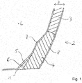
- second foam 4 used in the trailing edge end web 2 has a higher density in the region of the transition to the rotor blade half shell 1 than first foam 3 in a central region of the trailing edge end web 2 seen along a height H.
- the second foam 4 extends along the Contact area between the trailing edge end web 2 and the rotor blade half shell 1.
- Fig. 1 shows core materials 3, 4, 6 in cross section of the trailing edge end web 2.
- a first core material 3 has a first specific density in the range of 60 kg / m 3 when using PVC foam and of approx. 100 kg when using PET foam / m 3 , each with a fluctuation range of ⁇ 20 kg / m 3 . Only a part of the first core material 3 is shown. The entire central area, which is determined by the first foam 3, can be in Fig.1 continue upwards and extend to a second foam 4, which borders on the other rotor blade half shell, not shown.
- the specification of the specific density is the specific weight of the foam per cubic meter, i.e. the weight of the foam per cubic meter after it has been foamed, but before the laminate component and thus the foamed first foam 3 have been soaked with resin in the infusion process.
- a strip of the second foam 4 is provided between the rotor blade half-shell 1 and the first foam 3 and has a significantly higher specific density, namely greater than 200 kg / m 3 , preferably greater than 300 kg / m 3 .
- the rear edge end web 2 has a first thickness D in the region of the first foam 3.
- a thickness D of the trailing edge end web 2 preferably initially increases conically, in order then to have a constant second thickness D in the direction of the rotor blade half shell 1, which is preferably greater, however, than the first thickness D.
- the inner bar 5 has a core material made of a third foam 6.
- the third foam 6 is even denser than the first and the second foam 3, 4.
- the inner bar 5 can also consist of a pure epoxy resin bar.
- the inner bar 5 is arranged precisely on the inside of the second foam 4. It extends along the entire longitudinal extent of the trailing edge end web 2, preferably in the area in which the angle between the rotor blade half-shell 1 and the trailing edge end web 2 becomes significantly smaller than 180 °.
- the layers of an inner skin 7 are applied on the inside to the first foam 3, the second foam 4, the inner strip 5 and the semifinished product of the rotor blade half shell 1.
- the inner skin 7 can be fabric and / or jelly layers that contain glass fibers, carbon fibers or other fibers.
- the layers of an outer skin 8 are applied beforehand to the mold half-shell; this can also be tissue and / or gel layers containing glass fibers, carbon fibers or other fibers.
- the rotor blade half-shell 1 is glued together with an associated part of the rear edge end web 2 with a corresponding rotor blade half-shell with an associated part of the rear edge end web 2 to form the rotor blade with the rear edge end web.
- the trailing edge end web 2 has a transition area in the region of the second core material, for example the second foam 4, in which the thickness D of the second core material, for example the second foam 4, differs from the thickness D of the first core material, for example the first foam 3 , increases to the desired, preferably larger thickness D of the second core material.
- the second core material has a region in which the thickness D of the second core material remains essentially constant. The thickness D of the second core material is preferably greater than that of the first core material.
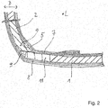
- FIG. 2 Another embodiment of the area between the rotor blade half shell 1 and the trailing edge end web 2 is shown.
- a rear edge belt 11 is arranged directly on the rear edge of the rotor blade and runs in the longitudinal direction L of the rotor blade.
- the rear edge belt 11 is constructed from fabric and / or jelly layers arranged over the entire thickness D of the rotor blade half-shell, which are layered as semi-finished products and soaked in an infusion process with the resin system.
- the rear edge belt preferably has a main fiber direction along the longitudinal direction L of the rotor blade.
- the rear edge belt 11 is significantly more stable than the rest of the sandwich area of the rotor blade half shell 1 in relation to tensile loads in the longitudinal direction L.
- the rear edge end web 2 is then laminated directly onto the rear edge belt 11 as part of the rotor blade half shell 1.
- the trailing edge end web 2 initially has a core material of a standard density in the area spaced apart from the rotor blade half shell 1, while a core material with a higher density is used in an area which adjoins the rotor blade half shell 1. In both cases, they are preferably foams.
- the standard foam has a density of about 60 kg / m 3 ⁇ 20 kg / m 3 when using PVC foam, the high density foam has a density of 200 - 300 kg / m3, preferably even higher densities.
- the rear edge belt 11 can have a somewhat arcuate shape in a cross section perpendicular to the longitudinal direction L and essentially represents a rectangular cross section.
- the rotor blade has, on the one hand, the above-mentioned triangular inner bar 5 from a material with a third specific density, the third specific density preferably being higher than the first and second specific density.
- An outer strip 9 with a triangular cross section is arranged along the outside of the contact line between the trailing edge end web 2 and the rotor blade half shell 1.
- the outer bar 9 has a fourth specific density.
- the rotor blade hub 1 closes at the rear with the rear edge belt 11.
- the outer bar 9 can also be a bar made of a hardened epoxy resin.
- the inner and outer strips 5, 9 are embedded in the semi-finished product of the rotor blade half-shell 1 and the trailing edge end web 2 and coated with the inner skin 7 and the outer skin 8.
- the semi-finished product with the core material of the trailing edge end web 2 and the inner and outer strips 5, 9 is glued to one another to form a laminate and cured.
- the transition point between the trailing edge end web 2 and the rotor blade half-shell 1 is, on the one hand, due to the increasing thickness D of the trailing edge end web 2 at the contact point, on the one hand due to the possibly greater thickness D of the core material of the trailing edge end web 2, and on the other hand also due to the introduction of the inner bar 5 and the outer bar 9 on the other hand, the adhesive connection becomes more stable because the core material has a higher average density than in areas which are further away from the contact point between the trailing edge end web 2 and the rotor blade half shell 1.
Claims (15)
- Pale de rotor pour une éolienne avec une entretoise de fermeture de bord arrière (2) qui est placée entre une demie coque de pale de rotor (1) côté aspiration et côté pression,
caractérisée en ce que l'entretoise de fermeture de bord arrière (2) est configurée comme un composant stratifié en construction en sandwich, avec un premier matériau de noyau (3) qui présente une première densité spécifique et un second matériau de noyau (4) placé le long d'une zone de transition entre l'entretoise de fermeture de bord arrière (2) et la demie coque de pale de rotor (1) qui présente une seconde densité spécifique et la seconde densité spécifique est plus grande que la première densité spécifique. - Pale de rotor selon la revendication 1, caractérisée en ce que la seconde densité spécifique a une valeur supérieure à 200 kg/m3.
- Pale de rotor selon la revendication 2, caractérisée en ce que la seconde densité spécifique a une valeur supérieure à 300 kg/m3.
- Pale de rotor selon la revendication 1, 2 ou 3, caractérisée en ce que la première densité spécifique a une valeur de 60 kg/m3 ± 20kg/m3 si une mousse de PET est utilisée et une valeur de 100 kg/m3 ± 20kg/m3 si une mousse de PVC est utilisée.
- Pale de rotor selon l'une des revendications précédentes, caractérisée en ce qu'une baguette intérieure (5) avec un troisième matériau de noyau 6) avec une troisième densité spécifique se trouve sur un côté intérieur de la pale de rotor le long de la zone de transition entre la demie coque de pale de rotor (1) et l'entretoise de fermeture de bord arrière (2), baguette intérieure qui est stratifiée avec la demie coque de pale de rotor (1) et l'entretoise de fermeture de bord arrière (2).
- Pale de rotor selon la revendication 5, caractérisée en ce que la troisième densité spécifique présente, avant la stratification, une valeur égale ou supérieure à la seconde densité spécifique.
- Pale de rotor selon l'une des revendications précédentes, caractérisée en ce qu'une baguette extérieure (9) avec une quatrième densité spécifique qui est supérieure à la première, à la seconde et à la troisième densité spécifique est placée sur le côté extérieur de la pale de rotor le long de la zone de transition.
- Pale de rotor selon la revendication 7, caractérisée en ce qu'une sangle de bord arrière (11) s'étend le long des bords arrière des deux demies coques de pale de rotor (1) et que le second matériau de noyau (4) et/ou le troisième matériau de noyau (6) présentent un contact direct avec la sangle de bord arrière (11).
- Procédé pour la fabrication d'une pale de rotor avec une entretoise de fermeture de bord arrière (2) d'une éolienne, un second matériau de noyau (4) avec une seconde densité spécifique étant placé dans une zone de transition qui s'étend le long d'un bord arrière de demie coque de pale de rotor entre l'entretoise de fermeture de bord arrière (2) et une demie coque de pale de rotor (1), un premier matériau de noyau (3) avec une première densité spécifique étant placé le long du second matériau de noyau (4) sur un côté opposé à la demie pale de rotor (1) et la seconde densité spécifique étant sélectionnée supérieure à la première densité spécifique.
- Procédé selon la revendication 9, caractérisé en ce que l'ensemble de l'arrangement des produits semi-finis dans la demie coque de pale de rotor (1) et l'entretoise de fermeture de bord arrière (2), y compris du premier et du second matériau de noyau (3, 4) et d'une baguette intérieure (5) et d'une baguette extérieure (9), est traité par infusion avec un système de résine thermodurcissable.
- Procédé selon la revendication 9 ou 10, caractérisé en ce qu'une demie coque de pale de rotor côté aspiration et une demie coque de pale de rotor côté pression (1) sont reliées l'une à l'autre avec l'entretoise de fermeture de bord arrière (2).
- Procédé selon l'une des revendications 9 à 11, caractérisé en ce que des couches extérieures et des couches intérieures, le premier et le second matériau de noyau (3, 4) de l'entretoise de fermeture de bord arrière (2) et la baguette intérieure (5) et la baguette extérieure (9) sont insérées dans une demie coque moulée.
- Procédé selon l'une des revendications 9 à 12, caractérisé en ce qu'un troisième matériau de noyau (6) est placé à l'intérieur le long du bord arrière de la demie coque de pale de rotor et directement sur le second matériau de noyau (4) et sur le bord arrière de la demie pale de rotor, troisième matériau dont la densité spécifique a une valeur supérieure à celle de la première densité spécifique et une valeur égale ou supérieure à celle de la seconde densité spécifique.
- Procédé selon l'une des revendications 9 à 13, caractérisé en ce que la baguette extérieure (9) est placée à l'extérieur le long du bord arrière de la demie coque de pale de rotor et directement sur le second matériau de noyau (4) et sur le bord arrière de la demie coque de pale de rotor, baguette extérieure dont la densité spécifique a une valeur supérieure à celle de la première, de la seconde et de la troisième densité spécifique.
- Procédé selon la revendication 14, caractérisé en ce qu'un quatrième matériau de noyau de la baguette extérieure (9) est en une résine époxy ou une résine polyuréthane.
Applications Claiming Priority (1)
| Application Number | Priority Date | Filing Date | Title |
|---|---|---|---|
| DE102016011757.5A DE102016011757A1 (de) | 2016-09-22 | 2016-09-22 | Rotorblatt mit Abschlusssteg |
Publications (2)
| Publication Number | Publication Date |
|---|---|
| EP3299613A1 EP3299613A1 (fr) | 2018-03-28 |
| EP3299613B1 true EP3299613B1 (fr) | 2020-01-08 |
Family
ID=59858647
Family Applications (1)
| Application Number | Title | Priority Date | Filing Date |
|---|---|---|---|
| EP17190853.6A Active EP3299613B1 (fr) | 2016-09-22 | 2017-09-13 | Pale de rotor ayant un élément de liaison d'extrémité |
Country Status (4)
| Country | Link |
|---|---|
| EP (1) | EP3299613B1 (fr) |
| DE (1) | DE102016011757A1 (fr) |
| DK (1) | DK3299613T3 (fr) |
| ES (1) | ES2781948T3 (fr) |
Families Citing this family (4)
| Publication number | Priority date | Publication date | Assignee | Title |
|---|---|---|---|---|
| US11486348B2 (en) * | 2016-07-19 | 2022-11-01 | Lm Wind Power Us Technology Aps | Wind turbine blade with flatback segment and related method |
| DE102017004058A1 (de) * | 2017-04-27 | 2018-10-31 | Senvion Gmbh | Rotorblatt einer windenergieanlage und verfahren zum herstellen eines solchen, abschlusssteg eines rotorblatts und verwendung eines solchen |
| DE102018005030A1 (de) | 2018-06-26 | 2020-01-02 | Senvion Gmbh | Rotorblatt mit Steg in Wabensandwichbauweise |
| EP3736436B1 (fr) * | 2019-05-09 | 2022-12-28 | Siemens Gamesa Renewable Energy A/S | Pale de rotor pour éolienne |
Family Cites Families (7)
| Publication number | Priority date | Publication date | Assignee | Title |
|---|---|---|---|---|
| DE3014347C2 (de) * | 1980-04-15 | 1983-05-26 | Messerschmitt-Bölkow-Blohm GmbH, 8000 München | Verfahren zur Herstellung von schaumkerngestützen, faserverstärkten Kunststoff-Formkörpern wie Flügel, Rotorblätter etc. großer Längen-und Breitenausdehnung |
| DE102010038408B4 (de) * | 2010-07-26 | 2020-11-19 | Airbus Operations Gmbh | Strukturelement für ein Luft- und Raumfahrzeug und Verfahren zum Herstellen eines derartigen Strukturelementes |
| DE102011077609B4 (de) * | 2011-06-16 | 2015-01-22 | Senvion Se | Fertigung einer Rotorblattschale |
| DE102011082664C5 (de) * | 2011-09-14 | 2017-08-10 | Senvion Gmbh | Form zur Herstellung eines Steges und Steg für ein Rotorblatt einer Windenergieanlage |
| EP2662204A1 (fr) * | 2012-05-07 | 2013-11-13 | Nordex Energy GmbH | Procédé, composant préfabriqué et moule de fabrication d'une pièce d'éolienne |
| DE102014203936B4 (de) | 2014-03-04 | 2016-03-24 | Senvion Gmbh | Verfahren zum Herstellen eines Rotorblatts einer Windenergieanlage, Rotorblatt und Windenergieanlage |
| CN104696167B (zh) * | 2014-12-24 | 2017-06-20 | 中国科学院工程热物理研究所 | 一种钝尾缘风力涡轮机叶片及其实施装置与方法 |
-
2016
- 2016-09-22 DE DE102016011757.5A patent/DE102016011757A1/de not_active Withdrawn
-
2017
- 2017-09-13 DK DK17190853.6T patent/DK3299613T3/da active
- 2017-09-13 EP EP17190853.6A patent/EP3299613B1/fr active Active
- 2017-09-13 ES ES17190853T patent/ES2781948T3/es active Active
Non-Patent Citations (1)
| Title |
|---|
| None * |
Also Published As
| Publication number | Publication date |
|---|---|
| ES2781948T3 (es) | 2020-09-09 |
| DE102016011757A1 (de) | 2018-03-22 |
| DK3299613T3 (da) | 2020-04-14 |
| EP3299613A1 (fr) | 2018-03-28 |
Similar Documents
| Publication | Publication Date | Title |
|---|---|---|
| EP2904262B1 (fr) | Composant composite pour la pale de rotor d'une éolienne | |
| EP3299613B1 (fr) | Pale de rotor ayant un élément de liaison d'extrémité | |
| EP2363599B2 (fr) | Pale de rotor pour une éolienne, éolienne et procédé de fabrication d'une pale de rotor | |
| DE102011078951B4 (de) | Verfahren zum Herstellen eines Rotorblatts für eine Windenergieanlage, Sandwich-Preform und Rotorblatt für eine Windenergieanlage | |
| EP2567807B1 (fr) | Procédé de fabrication d'un composant de pale de rotor d'éolienne doté d'une courroie principale préfabriquée | |
| EP3496936B1 (fr) | Semelle de longeron en éléments préfabriqués et tissu non-tissé et son procédé de production | |
| EP2666615B1 (fr) | Procédé de fabrication d'une demi-coque pour pale de rotor d'éolienne ou d'une pale de rotor d'éolienne et moule de fabrication à cette fin | |
| DE102009039534A1 (de) | Composite-Körper | |
| WO2005011964A1 (fr) | Structure de support | |
| CH666410A5 (de) | Ski. | |
| EP3018342B1 (fr) | Procede de fabrication d'une pale de rotor d'eolienne | |
| EP2561977B1 (fr) | Procédé de fabrication d'un élément d'âme de rotor d'éolienne doté d'une structure principale renforcée de fibres de carbone | |
| EP2670581B1 (fr) | Procédé, semi-produit pour la production d'un composant renforcé par des fibres d'une éolienne et utilisation du semi-produit | |
| DE102015007289A1 (de) | Rotorblatt, Rotorblattgurt und Verfahren zum Herstellen eines Rotorblattgurts | |
| EP3260697A1 (fr) | Sangle de bord arrière comprenant une fente à section transversale | |
| DE102005030939A1 (de) | Verfahren zur Herstellung eines im Wesentlichen schalenförmigen Bauteils | |
| EP3535115B1 (fr) | Pale de rotor courbe comportant des produits pultrudés, et procédé de fabrication de ladite pale | |
| EP2890552B1 (fr) | Procédé de réalisation d'une pale de rotor et pale de rotor d'éolienne | |
| EP3486476B1 (fr) | Entretoise pour une pale de rotor d'une éolienne et procédé de fabrication d'une entretoise | |
| EP3551438B1 (fr) | Membrure de bord de fuite d'une pale de rotor d'une installation éolienne, pale de rotor et procédé de fabrication d'une membrure de bord de fuite | |
| EP3482918A1 (fr) | Procédé de fabrication d'une entretoise d'une pale de rotor d'une éolienne | |
| DE102021105792A1 (de) | Sandwichbauteil, Turbinen-Strahltriebwerk und Verfahren zu dessen Herstellung | |
| EP3015702B1 (fr) | Pale de rotor pour une eolienne et procede de fabrication d'une pale de rotor | |
| EP3587801A1 (fr) | Pale de rotor pourvue d'élément de liaison de construction en sandwich nid d'abeilles |
Legal Events
| Date | Code | Title | Description |
|---|---|---|---|
| PUAI | Public reference made under article 153(3) epc to a published international application that has entered the european phase |
Free format text: ORIGINAL CODE: 0009012 |
|
| STAA | Information on the status of an ep patent application or granted ep patent |
Free format text: STATUS: THE APPLICATION HAS BEEN PUBLISHED |
|
| AK | Designated contracting states |
Kind code of ref document: A1 Designated state(s): AL AT BE BG CH CY CZ DE DK EE ES FI FR GB GR HR HU IE IS IT LI LT LU LV MC MK MT NL NO PL PT RO RS SE SI SK SM TR |
|
| AX | Request for extension of the european patent |
Extension state: BA ME |
|
| STAA | Information on the status of an ep patent application or granted ep patent |
Free format text: STATUS: REQUEST FOR EXAMINATION WAS MADE |
|
| 17P | Request for examination filed |
Effective date: 20180827 |
|
| RBV | Designated contracting states (corrected) |
Designated state(s): AL AT BE BG CH CY CZ DE DK EE ES FI FR GB GR HR HU IE IS IT LI LT LU LV MC MK MT NL NO PL PT RO RS SE SI SK SM TR |
|
| GRAP | Despatch of communication of intention to grant a patent |
Free format text: ORIGINAL CODE: EPIDOSNIGR1 |
|
| STAA | Information on the status of an ep patent application or granted ep patent |
Free format text: STATUS: GRANT OF PATENT IS INTENDED |
|
| INTG | Intention to grant announced |
Effective date: 20190212 |
|
| GRAS | Grant fee paid |
Free format text: ORIGINAL CODE: EPIDOSNIGR3 |
|
| GRAJ | Information related to disapproval of communication of intention to grant by the applicant or resumption of examination proceedings by the epo deleted |
Free format text: ORIGINAL CODE: EPIDOSDIGR1 |
|
| GRAL | Information related to payment of fee for publishing/printing deleted |
Free format text: ORIGINAL CODE: EPIDOSDIGR3 |
|
| STAA | Information on the status of an ep patent application or granted ep patent |
Free format text: STATUS: REQUEST FOR EXAMINATION WAS MADE |
|
| GRAP | Despatch of communication of intention to grant a patent |
Free format text: ORIGINAL CODE: EPIDOSNIGR1 |
|
| STAA | Information on the status of an ep patent application or granted ep patent |
Free format text: STATUS: GRANT OF PATENT IS INTENDED |
|
| INTC | Intention to grant announced (deleted) | ||
| INTG | Intention to grant announced |
Effective date: 20190717 |
|
| GRAA | (expected) grant |
Free format text: ORIGINAL CODE: 0009210 |
|
| STAA | Information on the status of an ep patent application or granted ep patent |
Free format text: STATUS: THE PATENT HAS BEEN GRANTED |
|
| AK | Designated contracting states |
Kind code of ref document: B1 Designated state(s): AL AT BE BG CH CY CZ DE DK EE ES FI FR GB GR HR HU IE IS IT LI LT LU LV MC MK MT NL NO PL PT RO RS SE SI SK SM TR |
|
| REG | Reference to a national code |
Ref country code: GB Ref legal event code: FG4D Free format text: NOT ENGLISH |
|
| REG | Reference to a national code |
Ref country code: CH Ref legal event code: EP |
|
| REG | Reference to a national code |
Ref country code: DE Ref legal event code: R096 Ref document number: 502017003427 Country of ref document: DE |
|
| REG | Reference to a national code |
Ref country code: IE Ref legal event code: FG4D Free format text: LANGUAGE OF EP DOCUMENT: GERMAN |
|
| REG | Reference to a national code |
Ref country code: AT Ref legal event code: REF Ref document number: 1223041 Country of ref document: AT Kind code of ref document: T Effective date: 20200215 |
|
| REG | Reference to a national code |
Ref country code: DK Ref legal event code: T3 Effective date: 20200408 |
|
| REG | Reference to a national code |
Ref country code: NL Ref legal event code: MP Effective date: 20200108 |
|
| REG | Reference to a national code |
Ref country code: LT Ref legal event code: MG4D |
|
| PG25 | Lapsed in a contracting state [announced via postgrant information from national office to epo] |
Ref country code: LT Free format text: LAPSE BECAUSE OF FAILURE TO SUBMIT A TRANSLATION OF THE DESCRIPTION OR TO PAY THE FEE WITHIN THE PRESCRIBED TIME-LIMIT Effective date: 20200108 Ref country code: NO Free format text: LAPSE BECAUSE OF FAILURE TO SUBMIT A TRANSLATION OF THE DESCRIPTION OR TO PAY THE FEE WITHIN THE PRESCRIBED TIME-LIMIT Effective date: 20200408 Ref country code: NL Free format text: LAPSE BECAUSE OF FAILURE TO SUBMIT A TRANSLATION OF THE DESCRIPTION OR TO PAY THE FEE WITHIN THE PRESCRIBED TIME-LIMIT Effective date: 20200108 Ref country code: FI Free format text: LAPSE BECAUSE OF FAILURE TO SUBMIT A TRANSLATION OF THE DESCRIPTION OR TO PAY THE FEE WITHIN THE PRESCRIBED TIME-LIMIT Effective date: 20200108 Ref country code: RS Free format text: LAPSE BECAUSE OF FAILURE TO SUBMIT A TRANSLATION OF THE DESCRIPTION OR TO PAY THE FEE WITHIN THE PRESCRIBED TIME-LIMIT Effective date: 20200108 Ref country code: PT Free format text: LAPSE BECAUSE OF FAILURE TO SUBMIT A TRANSLATION OF THE DESCRIPTION OR TO PAY THE FEE WITHIN THE PRESCRIBED TIME-LIMIT Effective date: 20200531 |
|
| PG25 | Lapsed in a contracting state [announced via postgrant information from national office to epo] |
Ref country code: HR Free format text: LAPSE BECAUSE OF FAILURE TO SUBMIT A TRANSLATION OF THE DESCRIPTION OR TO PAY THE FEE WITHIN THE PRESCRIBED TIME-LIMIT Effective date: 20200108 Ref country code: LV Free format text: LAPSE BECAUSE OF FAILURE TO SUBMIT A TRANSLATION OF THE DESCRIPTION OR TO PAY THE FEE WITHIN THE PRESCRIBED TIME-LIMIT Effective date: 20200108 Ref country code: SE Free format text: LAPSE BECAUSE OF FAILURE TO SUBMIT A TRANSLATION OF THE DESCRIPTION OR TO PAY THE FEE WITHIN THE PRESCRIBED TIME-LIMIT Effective date: 20200108 Ref country code: GR Free format text: LAPSE BECAUSE OF FAILURE TO SUBMIT A TRANSLATION OF THE DESCRIPTION OR TO PAY THE FEE WITHIN THE PRESCRIBED TIME-LIMIT Effective date: 20200409 Ref country code: IS Free format text: LAPSE BECAUSE OF FAILURE TO SUBMIT A TRANSLATION OF THE DESCRIPTION OR TO PAY THE FEE WITHIN THE PRESCRIBED TIME-LIMIT Effective date: 20200508 Ref country code: BG Free format text: LAPSE BECAUSE OF FAILURE TO SUBMIT A TRANSLATION OF THE DESCRIPTION OR TO PAY THE FEE WITHIN THE PRESCRIBED TIME-LIMIT Effective date: 20200408 |
|
| REG | Reference to a national code |
Ref country code: ES Ref legal event code: FG2A Ref document number: 2781948 Country of ref document: ES Kind code of ref document: T3 Effective date: 20200909 |
|
| REG | Reference to a national code |
Ref country code: DE Ref legal event code: R097 Ref document number: 502017003427 Country of ref document: DE |
|
| PG25 | Lapsed in a contracting state [announced via postgrant information from national office to epo] |
Ref country code: CZ Free format text: LAPSE BECAUSE OF FAILURE TO SUBMIT A TRANSLATION OF THE DESCRIPTION OR TO PAY THE FEE WITHIN THE PRESCRIBED TIME-LIMIT Effective date: 20200108 Ref country code: RO Free format text: LAPSE BECAUSE OF FAILURE TO SUBMIT A TRANSLATION OF THE DESCRIPTION OR TO PAY THE FEE WITHIN THE PRESCRIBED TIME-LIMIT Effective date: 20200108 Ref country code: EE Free format text: LAPSE BECAUSE OF FAILURE TO SUBMIT A TRANSLATION OF THE DESCRIPTION OR TO PAY THE FEE WITHIN THE PRESCRIBED TIME-LIMIT Effective date: 20200108 Ref country code: SM Free format text: LAPSE BECAUSE OF FAILURE TO SUBMIT A TRANSLATION OF THE DESCRIPTION OR TO PAY THE FEE WITHIN THE PRESCRIBED TIME-LIMIT Effective date: 20200108 Ref country code: SK Free format text: LAPSE BECAUSE OF FAILURE TO SUBMIT A TRANSLATION OF THE DESCRIPTION OR TO PAY THE FEE WITHIN THE PRESCRIBED TIME-LIMIT Effective date: 20200108 |
|
| PLBE | No opposition filed within time limit |
Free format text: ORIGINAL CODE: 0009261 |
|
| STAA | Information on the status of an ep patent application or granted ep patent |
Free format text: STATUS: NO OPPOSITION FILED WITHIN TIME LIMIT |
|
| 26N | No opposition filed |
Effective date: 20201009 |
|
| PG25 | Lapsed in a contracting state [announced via postgrant information from national office to epo] |
Ref country code: IT Free format text: LAPSE BECAUSE OF FAILURE TO SUBMIT A TRANSLATION OF THE DESCRIPTION OR TO PAY THE FEE WITHIN THE PRESCRIBED TIME-LIMIT Effective date: 20200108 |
|
| PG25 | Lapsed in a contracting state [announced via postgrant information from national office to epo] |
Ref country code: SI Free format text: LAPSE BECAUSE OF FAILURE TO SUBMIT A TRANSLATION OF THE DESCRIPTION OR TO PAY THE FEE WITHIN THE PRESCRIBED TIME-LIMIT Effective date: 20200108 Ref country code: PL Free format text: LAPSE BECAUSE OF FAILURE TO SUBMIT A TRANSLATION OF THE DESCRIPTION OR TO PAY THE FEE WITHIN THE PRESCRIBED TIME-LIMIT Effective date: 20200108 |
|
| REG | Reference to a national code |
Ref country code: CH Ref legal event code: PL |
|
| REG | Reference to a national code |
Ref country code: BE Ref legal event code: MM Effective date: 20200930 |
|
| PG25 | Lapsed in a contracting state [announced via postgrant information from national office to epo] |
Ref country code: LU Free format text: LAPSE BECAUSE OF NON-PAYMENT OF DUE FEES Effective date: 20200913 |
|
| PG25 | Lapsed in a contracting state [announced via postgrant information from national office to epo] |
Ref country code: BE Free format text: LAPSE BECAUSE OF NON-PAYMENT OF DUE FEES Effective date: 20200930 Ref country code: CH Free format text: LAPSE BECAUSE OF NON-PAYMENT OF DUE FEES Effective date: 20200930 Ref country code: LI Free format text: LAPSE BECAUSE OF NON-PAYMENT OF DUE FEES Effective date: 20200930 Ref country code: IE Free format text: LAPSE BECAUSE OF NON-PAYMENT OF DUE FEES Effective date: 20200913 |
|
| PG25 | Lapsed in a contracting state [announced via postgrant information from national office to epo] |
Ref country code: TR Free format text: LAPSE BECAUSE OF FAILURE TO SUBMIT A TRANSLATION OF THE DESCRIPTION OR TO PAY THE FEE WITHIN THE PRESCRIBED TIME-LIMIT Effective date: 20200108 Ref country code: MT Free format text: LAPSE BECAUSE OF FAILURE TO SUBMIT A TRANSLATION OF THE DESCRIPTION OR TO PAY THE FEE WITHIN THE PRESCRIBED TIME-LIMIT Effective date: 20200108 Ref country code: CY Free format text: LAPSE BECAUSE OF FAILURE TO SUBMIT A TRANSLATION OF THE DESCRIPTION OR TO PAY THE FEE WITHIN THE PRESCRIBED TIME-LIMIT Effective date: 20200108 |
|
| REG | Reference to a national code |
Ref country code: DE Ref legal event code: R081 Ref document number: 502017003427 Country of ref document: DE Owner name: SIEMENS GAMESA RENEWABLE ENERGY SERVICE GMBH, DE Free format text: FORMER OWNER: SENVION GMBH, 22297 HAMBURG, DE |
|
| PG25 | Lapsed in a contracting state [announced via postgrant information from national office to epo] |
Ref country code: MK Free format text: LAPSE BECAUSE OF FAILURE TO SUBMIT A TRANSLATION OF THE DESCRIPTION OR TO PAY THE FEE WITHIN THE PRESCRIBED TIME-LIMIT Effective date: 20200108 Ref country code: MC Free format text: LAPSE BECAUSE OF FAILURE TO SUBMIT A TRANSLATION OF THE DESCRIPTION OR TO PAY THE FEE WITHIN THE PRESCRIBED TIME-LIMIT Effective date: 20200108 Ref country code: AL Free format text: LAPSE BECAUSE OF FAILURE TO SUBMIT A TRANSLATION OF THE DESCRIPTION OR TO PAY THE FEE WITHIN THE PRESCRIBED TIME-LIMIT Effective date: 20200108 |
|
| REG | Reference to a national code |
Ref country code: GB Ref legal event code: 732E Free format text: REGISTERED BETWEEN 20230727 AND 20230802 |
|
| PGFP | Annual fee paid to national office [announced via postgrant information from national office to epo] |
Ref country code: GB Payment date: 20230921 Year of fee payment: 7 |
|
| REG | Reference to a national code |
Ref country code: AT Ref legal event code: MM01 Ref document number: 1223041 Country of ref document: AT Kind code of ref document: T Effective date: 20220913 |
|
| PGFP | Annual fee paid to national office [announced via postgrant information from national office to epo] |
Ref country code: FR Payment date: 20230918 Year of fee payment: 7 Ref country code: DK Payment date: 20230921 Year of fee payment: 7 Ref country code: DE Payment date: 20230919 Year of fee payment: 7 |
|
| PGFP | Annual fee paid to national office [announced via postgrant information from national office to epo] |
Ref country code: ES Payment date: 20231019 Year of fee payment: 7 |
|
| PG25 | Lapsed in a contracting state [announced via postgrant information from national office to epo] |
Ref country code: AT Free format text: LAPSE BECAUSE OF NON-PAYMENT OF DUE FEES Effective date: 20220913 |