EP2321105B1 - Verfahren und fertigungsform zur fertigung eines rotorblattes für eine windenergieanlage - Google Patents
Verfahren und fertigungsform zur fertigung eines rotorblattes für eine windenergieanlage Download PDFInfo
- Publication number
- EP2321105B1 EP2321105B1 EP09768954A EP09768954A EP2321105B1 EP 2321105 B1 EP2321105 B1 EP 2321105B1 EP 09768954 A EP09768954 A EP 09768954A EP 09768954 A EP09768954 A EP 09768954A EP 2321105 B1 EP2321105 B1 EP 2321105B1
- Authority
- EP
- European Patent Office
- Prior art keywords
- manufacturing mould
- manufacturing
- rotor blade
- portions
- mould
- Prior art date
- Legal status (The legal status is an assumption and is not a legal conclusion. Google has not performed a legal analysis and makes no representation as to the accuracy of the status listed.)
- Not-in-force
Links
- 238000004519 manufacturing process Methods 0.000 title claims description 127
- 238000000034 method Methods 0.000 title claims description 11
- 238000005516 engineering process Methods 0.000 claims description 8
- 239000011347 resin Substances 0.000 claims description 6
- 229920005989 resin Polymers 0.000 claims description 6
- 238000001802 infusion Methods 0.000 claims description 4
- 239000004033 plastic Substances 0.000 claims description 4
- 229920003023 plastic Polymers 0.000 claims description 4
- 239000000835 fiber Substances 0.000 claims description 2
- 239000003365 glass fiber Substances 0.000 claims description 2
- 238000001721 transfer moulding Methods 0.000 claims description 2
- OKTJSMMVPCPJKN-UHFFFAOYSA-N Carbon Chemical compound [C] OKTJSMMVPCPJKN-UHFFFAOYSA-N 0.000 claims 1
- 229910052799 carbon Inorganic materials 0.000 claims 1
- 238000009434 installation Methods 0.000 claims 1
- 238000010030 laminating Methods 0.000 claims 1
- 238000000465 moulding Methods 0.000 description 16
- 238000000926 separation method Methods 0.000 description 7
- 230000018109 developmental process Effects 0.000 description 6
- 239000000463 material Substances 0.000 description 5
- 239000000853 adhesive Substances 0.000 description 2
- 230000001070 adhesive effect Effects 0.000 description 2
- 229920000049 Carbon (fiber) Polymers 0.000 description 1
- 238000007792 addition Methods 0.000 description 1
- 230000015572 biosynthetic process Effects 0.000 description 1
- 239000004917 carbon fiber Substances 0.000 description 1
- 238000003475 lamination Methods 0.000 description 1
- 230000011218 segmentation Effects 0.000 description 1
- 239000013589 supplement Substances 0.000 description 1
- 238000009755 vacuum infusion Methods 0.000 description 1
Images


Classifications
-
- F—MECHANICAL ENGINEERING; LIGHTING; HEATING; WEAPONS; BLASTING
- F03—MACHINES OR ENGINES FOR LIQUIDS; WIND, SPRING, OR WEIGHT MOTORS; PRODUCING MECHANICAL POWER OR A REACTIVE PROPULSIVE THRUST, NOT OTHERWISE PROVIDED FOR
- F03D—WIND MOTORS
- F03D1/00—Wind motors with rotation axis substantially parallel to the air flow entering the rotor
- F03D1/06—Rotors
- F03D1/065—Rotors characterised by their construction elements
-
- B—PERFORMING OPERATIONS; TRANSPORTING
- B29—WORKING OF PLASTICS; WORKING OF SUBSTANCES IN A PLASTIC STATE IN GENERAL
- B29C—SHAPING OR JOINING OF PLASTICS; SHAPING OF MATERIAL IN A PLASTIC STATE, NOT OTHERWISE PROVIDED FOR; AFTER-TREATMENT OF THE SHAPED PRODUCTS, e.g. REPAIRING
- B29C33/00—Moulds or cores; Details thereof or accessories therefor
- B29C33/30—Mounting, exchanging or centering
-
- B—PERFORMING OPERATIONS; TRANSPORTING
- B29—WORKING OF PLASTICS; WORKING OF SUBSTANCES IN A PLASTIC STATE IN GENERAL
- B29C—SHAPING OR JOINING OF PLASTICS; SHAPING OF MATERIAL IN A PLASTIC STATE, NOT OTHERWISE PROVIDED FOR; AFTER-TREATMENT OF THE SHAPED PRODUCTS, e.g. REPAIRING
- B29C33/00—Moulds or cores; Details thereof or accessories therefor
- B29C33/34—Moulds or cores; Details thereof or accessories therefor movable, e.g. to or from the moulding station
-
- B—PERFORMING OPERATIONS; TRANSPORTING
- B29—WORKING OF PLASTICS; WORKING OF SUBSTANCES IN A PLASTIC STATE IN GENERAL
- B29C—SHAPING OR JOINING OF PLASTICS; SHAPING OF MATERIAL IN A PLASTIC STATE, NOT OTHERWISE PROVIDED FOR; AFTER-TREATMENT OF THE SHAPED PRODUCTS, e.g. REPAIRING
- B29C65/00—Joining or sealing of preformed parts, e.g. welding of plastics materials; Apparatus therefor
- B29C65/48—Joining or sealing of preformed parts, e.g. welding of plastics materials; Apparatus therefor using adhesives, i.e. using supplementary joining material; solvent bonding
- B29C65/50—Joining or sealing of preformed parts, e.g. welding of plastics materials; Apparatus therefor using adhesives, i.e. using supplementary joining material; solvent bonding using adhesive tape, e.g. thermoplastic tape; using threads or the like
- B29C65/5042—Joining or sealing of preformed parts, e.g. welding of plastics materials; Apparatus therefor using adhesives, i.e. using supplementary joining material; solvent bonding using adhesive tape, e.g. thermoplastic tape; using threads or the like covering both elements to be joined
-
- B—PERFORMING OPERATIONS; TRANSPORTING
- B29—WORKING OF PLASTICS; WORKING OF SUBSTANCES IN A PLASTIC STATE IN GENERAL
- B29C—SHAPING OR JOINING OF PLASTICS; SHAPING OF MATERIAL IN A PLASTIC STATE, NOT OTHERWISE PROVIDED FOR; AFTER-TREATMENT OF THE SHAPED PRODUCTS, e.g. REPAIRING
- B29C66/00—General aspects of processes or apparatus for joining preformed parts
- B29C66/50—General aspects of joining tubular articles; General aspects of joining long products, i.e. bars or profiled elements; General aspects of joining single elements to tubular articles, hollow articles or bars; General aspects of joining several hollow-preforms to form hollow or tubular articles
- B29C66/51—Joining tubular articles, profiled elements or bars; Joining single elements to tubular articles, hollow articles or bars; Joining several hollow-preforms to form hollow or tubular articles
- B29C66/54—Joining several hollow-preforms, e.g. half-shells, to form hollow articles, e.g. for making balls, containers; Joining several hollow-preforms, e.g. half-cylinders, to form tubular articles
- B29C66/543—Joining several hollow-preforms, e.g. half-shells, to form hollow articles, e.g. for making balls, containers; Joining several hollow-preforms, e.g. half-cylinders, to form tubular articles joining more than two hollow-preforms to form said hollow articles
-
- B—PERFORMING OPERATIONS; TRANSPORTING
- B29—WORKING OF PLASTICS; WORKING OF SUBSTANCES IN A PLASTIC STATE IN GENERAL
- B29C—SHAPING OR JOINING OF PLASTICS; SHAPING OF MATERIAL IN A PLASTIC STATE, NOT OTHERWISE PROVIDED FOR; AFTER-TREATMENT OF THE SHAPED PRODUCTS, e.g. REPAIRING
- B29C66/00—General aspects of processes or apparatus for joining preformed parts
- B29C66/50—General aspects of joining tubular articles; General aspects of joining long products, i.e. bars or profiled elements; General aspects of joining single elements to tubular articles, hollow articles or bars; General aspects of joining several hollow-preforms to form hollow or tubular articles
- B29C66/61—Joining from or joining on the inside
-
- B—PERFORMING OPERATIONS; TRANSPORTING
- B29—WORKING OF PLASTICS; WORKING OF SUBSTANCES IN A PLASTIC STATE IN GENERAL
- B29C—SHAPING OR JOINING OF PLASTICS; SHAPING OF MATERIAL IN A PLASTIC STATE, NOT OTHERWISE PROVIDED FOR; AFTER-TREATMENT OF THE SHAPED PRODUCTS, e.g. REPAIRING
- B29C66/00—General aspects of processes or apparatus for joining preformed parts
- B29C66/50—General aspects of joining tubular articles; General aspects of joining long products, i.e. bars or profiled elements; General aspects of joining single elements to tubular articles, hollow articles or bars; General aspects of joining several hollow-preforms to form hollow or tubular articles
- B29C66/63—Internally supporting the article during joining
- B29C66/636—Internally supporting the article during joining using a support which remains in the joined object
-
- B—PERFORMING OPERATIONS; TRANSPORTING
- B29—WORKING OF PLASTICS; WORKING OF SUBSTANCES IN A PLASTIC STATE IN GENERAL
- B29C—SHAPING OR JOINING OF PLASTICS; SHAPING OF MATERIAL IN A PLASTIC STATE, NOT OTHERWISE PROVIDED FOR; AFTER-TREATMENT OF THE SHAPED PRODUCTS, e.g. REPAIRING
- B29C66/00—General aspects of processes or apparatus for joining preformed parts
- B29C66/70—General aspects of processes or apparatus for joining preformed parts characterised by the composition, physical properties or the structure of the material of the parts to be joined; Joining with non-plastics material
- B29C66/72—General aspects of processes or apparatus for joining preformed parts characterised by the composition, physical properties or the structure of the material of the parts to be joined; Joining with non-plastics material characterised by the structure of the material of the parts to be joined
- B29C66/721—Fibre-reinforced materials
- B29C66/7214—Fibre-reinforced materials characterised by the length of the fibres
- B29C66/72141—Fibres of continuous length
-
- B—PERFORMING OPERATIONS; TRANSPORTING
- B29—WORKING OF PLASTICS; WORKING OF SUBSTANCES IN A PLASTIC STATE IN GENERAL
- B29C—SHAPING OR JOINING OF PLASTICS; SHAPING OF MATERIAL IN A PLASTIC STATE, NOT OTHERWISE PROVIDED FOR; AFTER-TREATMENT OF THE SHAPED PRODUCTS, e.g. REPAIRING
- B29C69/00—Combinations of shaping techniques not provided for in a single one of main groups B29C39/00 - B29C67/00, e.g. associations of moulding and joining techniques; Apparatus therefore
- B29C69/004—Combinations of shaping techniques not provided for in a single one of main groups B29C39/00 - B29C67/00, e.g. associations of moulding and joining techniques; Apparatus therefore making articles by joining parts moulded in separate cavities, said parts being in said separate cavities during said joining
-
- B—PERFORMING OPERATIONS; TRANSPORTING
- B29—WORKING OF PLASTICS; WORKING OF SUBSTANCES IN A PLASTIC STATE IN GENERAL
- B29D—PRODUCING PARTICULAR ARTICLES FROM PLASTICS OR FROM SUBSTANCES IN A PLASTIC STATE
- B29D99/00—Subject matter not provided for in other groups of this subclass
- B29D99/0025—Producing blades or the like, e.g. blades for turbines, propellers, or wings
-
- B—PERFORMING OPERATIONS; TRANSPORTING
- B29—WORKING OF PLASTICS; WORKING OF SUBSTANCES IN A PLASTIC STATE IN GENERAL
- B29C—SHAPING OR JOINING OF PLASTICS; SHAPING OF MATERIAL IN A PLASTIC STATE, NOT OTHERWISE PROVIDED FOR; AFTER-TREATMENT OF THE SHAPED PRODUCTS, e.g. REPAIRING
- B29C65/00—Joining or sealing of preformed parts, e.g. welding of plastics materials; Apparatus therefor
- B29C65/48—Joining or sealing of preformed parts, e.g. welding of plastics materials; Apparatus therefor using adhesives, i.e. using supplementary joining material; solvent bonding
- B29C65/4805—Joining or sealing of preformed parts, e.g. welding of plastics materials; Apparatus therefor using adhesives, i.e. using supplementary joining material; solvent bonding characterised by the type of adhesives
- B29C65/483—Reactive adhesives, e.g. chemically curing adhesives
-
- B—PERFORMING OPERATIONS; TRANSPORTING
- B29—WORKING OF PLASTICS; WORKING OF SUBSTANCES IN A PLASTIC STATE IN GENERAL
- B29C—SHAPING OR JOINING OF PLASTICS; SHAPING OF MATERIAL IN A PLASTIC STATE, NOT OTHERWISE PROVIDED FOR; AFTER-TREATMENT OF THE SHAPED PRODUCTS, e.g. REPAIRING
- B29C66/00—General aspects of processes or apparatus for joining preformed parts
- B29C66/70—General aspects of processes or apparatus for joining preformed parts characterised by the composition, physical properties or the structure of the material of the parts to be joined; Joining with non-plastics material
- B29C66/72—General aspects of processes or apparatus for joining preformed parts characterised by the composition, physical properties or the structure of the material of the parts to be joined; Joining with non-plastics material characterised by the structure of the material of the parts to be joined
- B29C66/721—Fibre-reinforced materials
- B29C66/7212—Fibre-reinforced materials characterised by the composition of the fibres
-
- B—PERFORMING OPERATIONS; TRANSPORTING
- B29—WORKING OF PLASTICS; WORKING OF SUBSTANCES IN A PLASTIC STATE IN GENERAL
- B29C—SHAPING OR JOINING OF PLASTICS; SHAPING OF MATERIAL IN A PLASTIC STATE, NOT OTHERWISE PROVIDED FOR; AFTER-TREATMENT OF THE SHAPED PRODUCTS, e.g. REPAIRING
- B29C70/00—Shaping composites, i.e. plastics material comprising reinforcements, fillers or preformed parts, e.g. inserts
- B29C70/04—Shaping composites, i.e. plastics material comprising reinforcements, fillers or preformed parts, e.g. inserts comprising reinforcements only, e.g. self-reinforcing plastics
- B29C70/28—Shaping operations therefor
- B29C70/40—Shaping or impregnating by compression not applied
- B29C70/42—Shaping or impregnating by compression not applied for producing articles of definite length, i.e. discrete articles
- B29C70/44—Shaping or impregnating by compression not applied for producing articles of definite length, i.e. discrete articles using isostatic pressure, e.g. pressure difference-moulding, vacuum bag-moulding, autoclave-moulding or expanding rubber-moulding
- B29C70/443—Shaping or impregnating by compression not applied for producing articles of definite length, i.e. discrete articles using isostatic pressure, e.g. pressure difference-moulding, vacuum bag-moulding, autoclave-moulding or expanding rubber-moulding and impregnating by vacuum or injection
-
- B—PERFORMING OPERATIONS; TRANSPORTING
- B29—WORKING OF PLASTICS; WORKING OF SUBSTANCES IN A PLASTIC STATE IN GENERAL
- B29C—SHAPING OR JOINING OF PLASTICS; SHAPING OF MATERIAL IN A PLASTIC STATE, NOT OTHERWISE PROVIDED FOR; AFTER-TREATMENT OF THE SHAPED PRODUCTS, e.g. REPAIRING
- B29C70/00—Shaping composites, i.e. plastics material comprising reinforcements, fillers or preformed parts, e.g. inserts
- B29C70/04—Shaping composites, i.e. plastics material comprising reinforcements, fillers or preformed parts, e.g. inserts comprising reinforcements only, e.g. self-reinforcing plastics
- B29C70/28—Shaping operations therefor
- B29C70/40—Shaping or impregnating by compression not applied
- B29C70/42—Shaping or impregnating by compression not applied for producing articles of definite length, i.e. discrete articles
- B29C70/46—Shaping or impregnating by compression not applied for producing articles of definite length, i.e. discrete articles using matched moulds, e.g. for deforming sheet moulding compounds [SMC] or prepregs
- B29C70/48—Shaping or impregnating by compression not applied for producing articles of definite length, i.e. discrete articles using matched moulds, e.g. for deforming sheet moulding compounds [SMC] or prepregs and impregnating the reinforcements in the closed mould, e.g. resin transfer moulding [RTM], e.g. by vacuum
-
- B—PERFORMING OPERATIONS; TRANSPORTING
- B29—WORKING OF PLASTICS; WORKING OF SUBSTANCES IN A PLASTIC STATE IN GENERAL
- B29L—INDEXING SCHEME ASSOCIATED WITH SUBCLASS B29C, RELATING TO PARTICULAR ARTICLES
- B29L2031/00—Other particular articles
- B29L2031/08—Blades for rotors, stators, fans, turbines or the like, e.g. screw propellers
- B29L2031/082—Blades, e.g. for helicopters
- B29L2031/085—Wind turbine blades
-
- Y—GENERAL TAGGING OF NEW TECHNOLOGICAL DEVELOPMENTS; GENERAL TAGGING OF CROSS-SECTIONAL TECHNOLOGIES SPANNING OVER SEVERAL SECTIONS OF THE IPC; TECHNICAL SUBJECTS COVERED BY FORMER USPC CROSS-REFERENCE ART COLLECTIONS [XRACs] AND DIGESTS
- Y02—TECHNOLOGIES OR APPLICATIONS FOR MITIGATION OR ADAPTATION AGAINST CLIMATE CHANGE
- Y02E—REDUCTION OF GREENHOUSE GAS [GHG] EMISSIONS, RELATED TO ENERGY GENERATION, TRANSMISSION OR DISTRIBUTION
- Y02E10/00—Energy generation through renewable energy sources
- Y02E10/70—Wind energy
- Y02E10/72—Wind turbines with rotation axis in wind direction
-
- Y—GENERAL TAGGING OF NEW TECHNOLOGICAL DEVELOPMENTS; GENERAL TAGGING OF CROSS-SECTIONAL TECHNOLOGIES SPANNING OVER SEVERAL SECTIONS OF THE IPC; TECHNICAL SUBJECTS COVERED BY FORMER USPC CROSS-REFERENCE ART COLLECTIONS [XRACs] AND DIGESTS
- Y02—TECHNOLOGIES OR APPLICATIONS FOR MITIGATION OR ADAPTATION AGAINST CLIMATE CHANGE
- Y02P—CLIMATE CHANGE MITIGATION TECHNOLOGIES IN THE PRODUCTION OR PROCESSING OF GOODS
- Y02P70/00—Climate change mitigation technologies in the production process for final industrial or consumer products
- Y02P70/50—Manufacturing or production processes characterised by the final manufactured product
Definitions
- the invention relates to a manufacturing mold for manufacturing a rotor blade for a wind turbine, wherein the finished rotor blade has at least in a region of its longitudinal extent, between a rotor blade root and a rotor blade tip, an aerodynamic cross-sectional profile having a profile leading edge (nose) and a trailing edge profile, over a Suction side and a pressure side of the cross-sectional profile are interconnected.
- the invention relates to a method for manufacturing a rotor blade for a wind energy plant.
- a generic manufacturing form is for example from the WO2004 / 043679 known.
- WO2007 / 054088 A1 discloses a manufacturing mold for rotor blades of a wind turbine, which consists of two moldings according to the preamble of claim 1.
- the invention is based on the object of a split production a rotor blade to improve such that the handling of the manufacturing form is facilitated and the finished rotor blade of this relief in its quality remains unaffected.
- This object is achieved in that the manufacturing form along at least one separating surface which extends in the longitudinal direction of the rotor blade and between the leading edge profile and trailing edge with simultaneous division of the suction side and the pressure side, in a production molding for the production of a profile leading edge rotor blade part and in a manufacturing mold part for producing a profile trailing edge comprehensive rotor blade profile part is divisible.
- the division of the production form is substantially orthogonal to the extension of the known production form mentioned above. This results in advantages in the separation process of the manufacturing moldings and the merge, wherein the finished rotor blade may also have advantages, because in each case the profile trailing edge and the leading edge profile can be made as a whole.
- the separation surface is approximately vertically oriented, so that the profile remains in a flat orientation.
- the production moldings can advantageously be disassembled and brought together again on the same level. It would also be conceivable to manufacture the profile so that the finished profile is oriented rather edgewise, wherein the manufacturing mold parts could be lifted and / or pivoted to their separation from each other.
- Under perpendicular is understood in particular vertical. About perpendicular means in particular up to ⁇ 15 ° from the vertical, preferably in the vertical.
- a development of the invention is characterized in that at least one of the manufacturing moldings in turn is divisible.
- a separation surface for dividing the divisible production molding is oriented approximately orthogonally to the separation surface for dividing the production moldings.
- a division as in the cited, known manufacturing form could be provided.
- the second separating surface could thus also extend substantially in the longitudinal direction of the rotor blade. But it would also be a transverse division of the manufacturing form and the rotor blade conceivable.
- a preferred embodiment of the manufacturing form according to the invention provides that the manufacturing mold is divisible into two production moldings, both of which in turn are each again divisible so that the rotor blade profile to be produced in them appears to be quartered approximately.
- At least two mutually divisible manufacturing moldings can remain connected to each other via a kind of joint to facilitate the closing of the mold.
- Another development of the invention is characterized in that one of the molded parts, despite division of the manufacturing form, at least largely formed and provided for forming an undivided profile leading edge.
- This advantageously avoids a problem with known production forms in that the production mold may not be closed precisely enough in the profile edge areas, the profile segments are not flush connected in these areas, and problems of aerodynamics or durability of the finished rotor blade in these areas occur ,
- a further development of the production form provides that at least one of the production mold parts has a mold assembly which can be mounted in a divided manufacturing mold and demounted prior to merging the production mold, so that profile regions can be produced seamlessly over the actual region of the production molding without this closing hinders the production form after production.
- the invention provides for a development that the manufacturing form is divisible to manufacture rotor blade parts in the manufacturing mold parts, and the manufacturing moldings, preferably to the complete manufacturing form, are merge again to connect rotor blade parts together, so that the rotor blade joined together in the manufacturing mold and can be made up.
- dowel pins or the like may be provided.
- Manufacturing moldings can be connected to each other, in particular lockable be.
- a further development of the invention advantageously provides that a work platform can be introduced between separate molded parts, which in particular facilitates the filling of the mold with material for the rotor blade to be manufactured.
- a working platform movable up and down is provided in the, preferably vertical separation area of two production mold parts.
- the work platform is preferably, at least temporarily, part of the manufacturing form.
- a method for manufacturing a rotor blade with a manufacturing mold preferably using a manufacturing method according to the invention, which is characterized in an independent solution of the task by dividing the manufacturing form, rotor blade parts are manufactured in parts of the manufacturing form and the manufacturing mold is closed again to connect the rotor blade parts together, preferably to stick together also independent protection is claimed.
- the rotor blade parts are manufactured with a plastic technology, preferably at least one resin and at least one fiber layer, in particular of glass fibers and / or carbon fibers, is used in the plastics technology.
- RTM Resin Transfer Molding
- RIM Resin Infusion Molding
- VAR vacuum assisted resin infusion
- At least one prefabricated belt is introduced into at least one part of the production mold or that parts of a split belt are introduced into at least two parts of the production mold.
- At least one web could be introduced into at least one part of the manufacturing mold, wherein at least one receptacle for the web can be provided for the form-fitting arrangement of the web on a rotor blade part, in particular the receptacle could be substantially in the form of a U-shape. profile-shaped rail are formed.
- a bridge a simple, prefabricated and inexpensive plate element to be installed.
- a parting surface is understood in particular to mean a parting plane and / or an abutment surface which may be curved and / or straight.
- the interface can also be partially curved and partially straight.
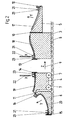
- Fig. 1 shows a cross section of an embodiment of a fully open, still empty, inventive manufacturing mold.
- the manufacturing mold is divided along two, mutually orthogonal parting surfaces 1, 2, each extending in the longitudinal direction of the manufacturing form in the drawing sheet in and out of this, in its cross section in four production mold parts 3 to 6.
- the manufacturing mold parts 3, 4 are by means of wheels 7 on the manufacturing mold part 4 on the ground 8 to their in Fig. 1 shown separation movable apart and in the direction of an arrow 9 again movable together.
- the further manufacturing mold parts 5 and 6 are each hinged over joints 10, 11 are arranged.
- These manufacturing moldings 5, 6 are in Fig. 1 shown in its open position and in its closed position, in which the cross-sectional profile of a rotor blade to be produced is recognizable, indicated by dashed lines 5 ', 6'.
- 3 to 6 attachable and removable before closing the manufacturing mold form additions 12 to 16 are arranged on the mold parts.
- the mold supplement 16 serves to be able to form a seamless, complete profile leading edge region of the rotor blade.
- Fig. 2 shows the cross section of the manufacturing form Fig. 1 with already some material for a rotor blade. Same components are, as well as in Fig. 3 , denoted by the same reference numerals.
- shell parts 17 to 20 of a rotor blade are already formed. These may preferably have been formed and shaped by means of vacuum infusion using fibrous webs and resin in the molded parts 3 to 6.
- the introduction of fibrous layers and the formation of vacuum chambers is facilitated by the inventive division of the manufacturing mold into manageable production moldings 3 to 6, as well as the handling of the rotor blade shell parts 17 to 20, especially in a possible committee only in one of the manufacturing mold parts 3 to 6.
- U-shaped receptacles 21 are arranged or integrally formed for webs 22, easily inserted into the webs 22 before closing the manufacturing mold and, for example, can be glued. These receptacles 21 are preferably located on belt parts 23, which were inserted into the manufacturing mold parts 17 to 20.
- Letters X, Y, Z symbolize the chronological order in which the first webs 22 are used, then the manufacturing mold parts 5, 6 are closed and finally the molded parts 3, 4 are moved together.
- Fig. 3 shows the closed manufacturing mold, in which a profile cross-section of a rotor blade can be seen. It is (exaggerated) indicated that the shell parts 18, 20 and 17, 19 are glued to each other via bonding lines 24 and the shell parts 17, 18 are glued together to form a profile trailing edge with adhesive 25 and the shell parts 19, 20 in the region of a molded Profile leading edge glued to each other with adhesive 26.
Description
- Die Erfindung betrifft eine Fertigungsform zur Fertigung eines Rotorblattes für eine Windenergieanlage, wobei das fertige Rotorblatt wenigstens in einem Bereich seiner Längserstreckung, zwischen einer Rotorblattwurzel und einer Rotorblattspitze, ein aerodynamisches Querschnittsprofil aufweist, das eine Profilvorderkante (Nase) und eine Profilhinterkante aufweist, die über eine Saugseite und eine Druckseite des Querschnittprofils miteinander verbunden sind.
- Des Weiteren betrifft die Erfindung ein Verfahren zur Fertigung eines Rotorblatts für eine Windenergieanlage.
- Eine gattungsgemäße Fertigungsform ist zum Beispiel aus der
WO2004/043679 bekannt. -
WO2007/054088 A1 offenbart eine Fertigungsform für Rotorblätter einer Windenergieanlage, die aus zwei Formteilen besteht gemäß dem Oberbegriff des Anspruchs 1. - Der Erfindung liegt die Aufgabe zugrunde, eine geteilte Fertigung eines Rotorblatts derart zu verbessern, dass die Handhabung der Fertigungsform erleichtert wird und das fertige Rotorblatt von dieser Erleichterung in seiner Qualität unbeeinträchtigt bleibt.
- Diese Aufgabe wird erfindungsgemäß dadurch gelöst, dass die Fertigungsform entlang wenigstens einer Trennfläche, die sich in Längsrichtung des Rotorblattes und zwischen der Profilvorderkante und der Profilhinterkante unter gleichzeitiger Teilung der Saugseite und der Druckseite erstreckt, in einen Fertigungsformteil zur Fertigung eines die Profilvorderkante umfassenden Rotorblattteiles und in einen Fertigungsformteil zur Fertigung eines die Profilhinterkante umfassenden Rotorblattprofilteils teilbar ist.
- Erfindungsgemäß erfolgt die Teilung der Fertigungsform im Wesentlichen orthogonal zu der TeiJung der weiter oben genannten bekannten Fertigungsform. Hierdurch ergeben sich Vorteile bei dem Trennungsvorgang der Fertigungsformteile und der Zusammenführung, wobei das fertige Rotorblatt ebenfalls Vorteile aufweisen kann, weil jeweils die Profilhinterkante und die Profilvorderkante im Ganzen gefertigt werden können.
- Vorzugsweise ist dabei die Trennfläche etwa lotrecht orientiert, so dass das Profil in einer flachen Orientierung verbleibt. Dadurch können die Fertigungsformteile mit Vorteil auf derselben Ebene auseinander- und wieder zusammengerückt werden. Es wäre aber auch denkbar, das Profil so zu fertigen, dass das fertige Profil eher hochkant orientiert ist, wobei die Fertigungsformteile zu ihrer Trennung voneinander abgehoben und/oder verschwenkt werden könnten. Unter lotrecht wird insbesondere vertikal verstanden. Etwa lotrecht bedeutet insbesondere bis zu ± 15° von der Vertikalen, bevorzugt in der Vertikalen.
- Eine Weiterbildung der Erfindung zeichnet sich dadurch aus, dass wenigstens einer der Fertigungsformteile seinerseits teilbar ist.
- Dies erleichtert mit Vorteil weiter die Handhabbarkeit der Formen und die Fertigung des Rotorblatts durch Segmentierung, wiederum ohne Qualitätseinbuße beim fertigen Rotorblatt.
- Nach einer nächsten Weiterbildung der Erfindung ist vorgesehen, dass eine Trennfläche zur Teilung des teilbaren Fertigungsformteils etwa orthogonal zur Trennfläche zur Teilung der Fertigungsformteile orientiert ist. Dadurch könnte insbesondere zusätzlich ganz oder abschnittweise eine Teilung wie bei der zitierten, bekannten Fertigungsform vorgesehen sein. Auch die zweite Trennfläche könnte sich somit im Wesentlichen in Längsrichtung des Rotorblattes erstrecken. Es wäre aber auch eine Querteilung der Fertigungsform und des Rotorblattes denkbar. Eine bevorzugte Ausführungsform der erfindungsgemäßen Fertigungsform sieht vor, dass die Fertigungsform in zwei Fertigungsformteile teilbar ist, die beide ihrerseits jeweils derart noch einmal teilbar sind, dass das in ihnen zu fertigende Rotorblattprofil etwa geviertelt erscheint.
- Wenigstens zwei voneinander teilbare Fertigungsformteile können über eine Art Gelenk miteinander verbunden bleiben, um das Schließen der Form zu erleichtern.
- Eine andere Weiterbildung der Erfindung zeichnet sich dadurch aus, dass einer der Fertigungsformteile, trotz Teilung der Fertigungsform, wenigstens weitgehend zur Ausformung einer ungeteilten Profilvorderkante ausgebildet und vorgesehen ist. Damit wird mit Vorteil ein Problem bekannter Fertigungsformen vermieden, dass die Fertigungsform eventuell in den Profilkantenbereichen nicht präzise genug bündig geschlossen wird, die Profilsegmente dadurch in diesen Bereichen nicht bündig miteinander verbunden werden und so Probleme der Aerodynamik oder der Haltbarkeit beim fertigen Rotorblatt in diesen Bereichen auftreten.
- Eine Weiterbildung der Fertigungsform sieht vor, dass wenigstens einer der Fertigungsformteile zu seiner Fertigungsformfortsetzung eine bei geteilter Fertigungsform montierbare und vor einer Zusammenführung der Fertigungsform demontierbare Formergänzung aufweist, so dass Profilbereiche nahtlos über den eigentlichen Bereich des Fertigungsformteils hinaus gefertigt werden können, ohne dass dies das Schließen der Fertigungsform nach der Fertigung hindert.
- Die Erfindung sieht nach einer Weiterbildung vor, dass die Fertigungsform teilbar ist, um Rotorblattteile in den Fertigungsformteilen zu fertigen, und die Fertigungsformteile, vorzugsweise zu der vollständigen Fertigungsform, wieder zusammenführbar sind, um Rotorblattteile miteinander zu verbinden, so dass das Rotorblatt in der Fertigungsform zusammengefügt und konfektioniert werden kann.
- Zum passgenauen Anschluss von Fertigungsformteilen aneinander oder zueinander können Führungselemente, insbesondere Passstifte oder dergleichen, vorgesehen sein. Fertigungsformteile können miteinander verbindbar, insbesondere verriegelbar, sein.
- Eine weitere Weiterbildung der Erfindung sieht mit Vorteil vor, dass zwischen voneinander getrennten Fertigungsformteilen eine Arbeitsplattform einbringbar ist, die insbesondere das Befüllen der Form mit Werkstoff für das zu fertigende Rotorblatt erleichtert. Vorzugsweise kann vorgesehen sein, dass eine auf und ab bewegbare Arbeitsplattform im, vorzugsweise lotrechten Trennungsbereich zweier Fertigungsformteile vorgesehen ist. Die Arbeitsplattform ist vorzugsweise, zumindest temporär, Bestandteil der Fertigungsform.
- Für ein Verfahren zur Fertigung eines Rotorblatts mit einer Fertigungsform, vorzugsweise unter Verwendung einer erfindungsgemäßen Fertigungsform, das sich in selbstständiger Lösung der gestellten Aufgabe dadurch auszeichnet, dass die Fertigungsform geteilt wird, Rotorblattteile in Teilen der Fertigungsform gefertigt werden und die Fertigungsform wieder geschlossen wird, um die Rotorblattteile miteinander zu verbinden, vorzugsweise miteinander zu verkleben, wird auch selbstständiger Schutz beansprucht.
- Bevorzugt werden die Rotorblattteile mit einer Kunststofftechnik gefertigt, vorzugsweise wird bei der Kunststofftechnik wenigstens ein Harz und wenigstens eine Faserlage, insbesondere aus Glasfasern und/oder Kohlefasern, verwendet.
- Insbesondere könnten für die Fertigung des Rotorblatts eine Spritzpresstechnik (Resin Transfer Moulding; RTM), eine Infusionstechnik (Resin Infusion Moulding; RIM) verwendet wird, insbesondere eine durch Vakuum unterstütze Infusionstechnik (Vacuum Assisted Resin Infusion; VAR) und/oder eine Laminiertechnik verwendet werden.
- Erfindungsgemäß kann vorgesehen sein, dass wenigstens ein vorgefertigter Gurt in wenigstens einen Teil der Fertigungsform eingebracht wird oder dass Teile eines geteilten Gurtes in wenigstens zwei Teile der Fertigungsform eingebracht werden.
- Vor dem Schließen der Fertigungsform könnte wenigstens ein Steg in wenigstens einen Teil der Fertigungsform eingebracht werden, wobei vorzugsweise zum formschlüssigen Anordnen des Steges an einem Rotorblattteil wenigstens eine Aufnahme für den Steg vorgesehen werden kann, insbesondere könnte die Aufnahme im Wesentlichen etwa in Form einer U-profilförmigen Schiene ausgebildet werden. Vorteilhaft kann als Steg ein einfaches, vorgefertigtes und kostengünstiges Plattenelement eingebaut werden.
- Im Rahmen der Erfindung ist unter einer Trennfläche insbesondere auch eine Trennebene und/oder eine Stoßfläche zu verstehen, die gekrümmt und/oder gerade sein kann. Hierbei kann die Trennfläche auch teilweise gekrümmt und teilweise gerade sein.
- Ein Ausführungsbeispiel der Erfindung, aus dem sich auch weitere erfinderische Merkmale ergeben können, auf die die Erfindung in ihrem Umfang aber nicht beschränkt ist, ist in der Zeichnung dargestellt. Es zeigen:
- Fig. 1
- einen Querschnitt eines Ausführungsbeispiels einer vollständig geöffneten, noch leeren, erfindungsgemäßen Fertigungsform,
- Fig. 2
- den Querschnitt gemäß
Fig. 1 bei teilweise mit Werkstoff bzw. Material für das zu fertigende Rotorblatt gefüllter Fertigungsform und - Fig. 3
- den Querschnitt bei geschlossener Fertigungsform mit einem Profilquerschnitt eines Rotorblattes in ihrem Inneren.
-
Fig. 1 zeigt einen Querschnitt eines Ausführungsbeispiels einer vollständig geöffneten, noch leeren, erfindungsgemäßen Fertigungsform. - Die Fertigungsform ist entlang zweier, zueinander orthogonaler Trennflächen 1, 2, die sich jeweils in Längsrichtung der Fertigungsform in das Zeichnungsblatt hinein und aus diesem heraus erstrecken, in ihrem Querschnitt in vier Fertigungsformteile 3 bis 6 geteilt.
- Die Fertigungsformteile 3, 4 sind mit Hilfe von Rädern 7 an dem Fertigungsformteil 4 auf dem Erdboden 8 zu ihrer in
Fig. 1 gezeigten Trennung auseinander fahrbar und in Richtung eines Pfeils 9 wieder zusammenfahrbar. An den Fertigungsformteilen 3, 4 sind die weiteren Fertigungsformteile 5 bzw. 6 jeweils abklappbar über Gelenke 10, 11 angeordnet. Diese Fertigungsformteile 5, 6 sind inFig. 1 in ihrer Öffnungsstellung gezeigt und in ihrer Schließstellung, in der das Querschnittsprofil eines zu fertigenden Rotorblatts erkennbar wird, mit gestrichelten Linien 5', 6' angedeutet. - Zusätzlich sind an den Fertigungsformteilen 3 bis 6 ansetzbare und vor dem Verschließen der Fertigungsform wieder abnehmbare Formergänzungen 12 bis 16 angeordnet. Insbesondere die Formergänzung 16 dient dazu, einen nahtlosen, vollständigen Profilvorderkantenbereich des Rotorblatts ausformen zu können.
-
Fig. 2 zeigt den Querschnitt der Fertigungsform ausFig. 1 mit bereits einigem Material für ein Rotorblatt. Gleiche Bauelemente sind, wie auch inFig. 3 , mit den gleichen Bezugszahlen bezeichnet. - In den Fertigungsformteilen 3 bis 6 sind insbesondere Schalenteile 17 bis 20 eines Rotorblattes bereits ausgeformt. Diese können bevorzugt mittels einer Vakuuminfusion unter Verwendung von Fasergelegen und Harz in den Fertigungsformteilen 3 bis 6 ausgebildet und geformt worden sein. Die Einbringung von Fasergelegen und die Ausbildung von Vakuumkammern wird durch die erfindungsgemäße Teilung der Fertigungsform in handlichere Fertigungsformteile 3 bis 6 erleichtert, ebenso wie die Handhabung der Rotorblattschalenteile 17 bis 20, insbesondere bei einem eventuellen Ausschuss nur in einem der Fertigungsformteile 3 bis 6. Die Verwendung von vorgeformten oder vorausgebildeten Teilen, insbesondere sogenannter Prepregs, in der erfindungsgemäßen Fertigungsform und bei dem erfindungsgemäßen Verfahren ist natürlich nicht ausgeschlossen.
- Zudem sind in den Schalenteilen 17 bis 20 U-förmige Aufnahmen 21 für Stege 22 angeordnet oder angeformt, in die Stege 22 vor dem Verschließen der Fertigungsform einfach eingesteckt und zum Beispiel verklebt werden können. Diese Aufnahmen 21 befinden sich vorzugsweise an Gurtteilen 23, die in die Fertigungsformteile 17 bis 20 eingelegt wurden.
- Buchstaben X, Y, Z symbolisieren die zeitliche Reihenfolge, in der zunächst die Stege 22 eingesetzt werden., dann die Fertigungsformteile 5, 6 zugeklappt und schließlich die Fertigungsformteile 3, 4 zusammengefahren werden.
-
Fig. 3 zeigt die geschlossene Fertigungsform, in der ein Profilquerschnitt eines Rotorblatts zu erkennen ist. Es ist (übertrieben) angedeutet, dass die Schalenteile 18, 20 und 17, 19 jeweils über Verklebungslinien 24 miteinander verklebt sind und die Schalenteile 17, 18 zur Ausbildung einer Profilhinterkante mit Kleber 25 miteinander verklebt sind und die Schalenteile 19, 20 im Bereich einer ausgeformten Profilvorderkante mit Kleber 26 miteinander verklebt sind.
Claims (14)
- Fertigungsform zur Fertigung eines Rotorblattes für eine Windenergieanlage, wobei das fertige Rotorblatt wenigstens in einem Bereich seiner Längserstreckung, zwischen einer Rotorblattwurzel und einer Rotorblattspitze, ein aerodynamisches Querschnittsprofil aufweist, das eine Profilvorderkante und eine Profilhinterkante aufweist, die über eine Saugseite und eine Druckseite des Querschnittprofils miteinander verbunden sind, dadurch gekennzeichnet, dass die Fertigungsform entlang wenigstens einer Trennfläche (1, 2), die sich in Längsrichtung des Rotorblattes und zwischen der Profilvorderkante und der Profilhinterkante unter gleichzeitiger Teilung der Saugseite und der Druckseite erstreckt, in einen Fertigungsformteil (4, 6) zur Fertigung eines die Profilvorderkante umfassenden Rotorblattteiles und in einen Fertigungsformteil (3, 5) zur Fertigung eines die Profilhinterkante umfassenden Rotorblattprofilteils teilbar ist.
- Fertigungsform nach Anspruch 1, dadurch gekennzeichnet, dass die Trennfläche (1) etwa lotrecht orientiert ist.
- Fertigungsform nach Anspruch 1 oder 2, dadurch gekennzeichnet, dass wenigstens eines der Fertigungsformteile (3-6) seinerseits teilbar ist.
- Fertigungsform nach Anspruch 3, dadurch gekennzeichnet, dass eine Trennfläche (2) zur Teilung des teilbaren Fertigungsformteils (3-6) etwa orthogonal zur Trennfläche (1) zur Teilung der Fertigungsformteile (3-6) orientiert ist.
- Fertigungsform nach Anspruch 3 und 4, dadurch gekennzeichnet, dass die Fertigungsform in zwei Fertigungsformteile (3-6) teilbar ist, die beide ihrerseits jeweils derart noch einmal teilbar sind, dass das in ihnen zu fertigende Rotorblattprofil etwa geviertelt erscheint.
- Fertigungsform nach einem der vorhergehenden Ansprüche, dadurch gekennzeichnet, dass wenigstens zwei voneinander teilbare Fertigungsformteile (3-6) über ein Gelenk (10, 11) miteinander verbunden bleiben, wobei insbesondere eines der Fertigungsformteile (3-6), trotz Teilung der Fertigungsform, wenigstens weitgehend zur Ausformung einer ungeteilten Profilvorderkante ausgebildet und vorgesehen ist, wobei insbesondere wenigstens einer der Fertigungsformteile (3-6) zu seiner Fertigungsformfortsetzung eine bei geteilter Fertigungsform montierbare und vor einer Zusammenführung der Fertigungsform demontierbare Formergänzung (12-16) aufweist.
- Fertigungsform nach einem der vorhergehenden Ansprüche, dadurch gekennzeichnet, dass die Fertigungsform teilbar ist, um Rotorblatteile in den Fertigungsformteilen (3-6) zu fertigen, und die Fertigungsformteile (3-6), vorzugsweise zu der vollständigen Fertigungsform, wieder zusammenführbar sind, um Rotorblattteile miteinander zu verbinden, wobei insbesondere zum passgenauen Anschluss von Fertigungsformteilen (3-6) aneinander oder zueinander Führungselemente, insbesondere Passstifte oder dergleichen, vorgesehen sind, wobei insbesondere Fertigungsformteile (3-6) miteinander verbindbar, insbesondere verriegelbar, sind.
- Fertigungsform nach einem der vorhergehenden Ansprüche, dadurch gekennzeichnet, dass zwischen voneinander getrennten Fertigungsformteilen (3-6) eine Arbeitsplattform einbringbar ist, wobei insbesondere eine auf und ab bewegbare Arbeitsplattform im Trennungsbereich zweier Fertigungsformteile (3-6) vorgesehen ist.
- Verfahren zur Fertigung eines Rotorblatts unter Verwendung einer Fertigungsform nach einem oder mehreren der vorhergehenden Ansprüche, dadurch gekennzeichnet, dass die Fertigungsform geteilt wird, Rotorblattteile (17-20) in Teilen (3-6) der Fertigungsform gefertigt werden und die Fertigungsform wieder geschlossen wird, um die Rotorblattteile (17-20) miteinander zu verbinden, vorzugsweise miteinander zu verkleben.
- Verfahren nach Anspruch 9, dadurch gekennzeichnet, dass die Rotorblattteile (17-20) mit einer Kunststofftechnik gefertigt werden, wobei insbesondere bei der Kunststofftechnik wenigstens ein Harz und wenigstens eine Faserlage, insbesondere aus Glasfasern und/oder Kohlefasern, verwendet wird, wobei insbesondere eine Spritzpresstechnik verwendet wird oder eine Infusionstechnik verwendet wird, insbesondere eine durch Vakuum unterstütze Infusionstechnik.
- Verfahren nach Anspruch 10, dadurch gekennzeichnet, dass eine Laminiertechnik verwendet wird.
- Verfahren nach einem der Ansprüche 9 bis 11, dadurch gekennzeichnet, dass wenigstens ein vorgefertigter Gurt (23) in wenigstens einen Teil der Fertigungsform eingebracht wird, wobei insbesondere Teile eines geteilten Gurtes (23) in wenigstens zwei Teile der Fertigungsform eingebracht werden.
- Verfahren nach einem der Ansprüche 9 bis 12, dadurch gekennzeichnet, dass vor dem Schließen der Fertigungsform wenigstens ein Steg (22) in wenigstens einen Teil der Fertigungsform eingebracht wird, wobei insbesondere zum formschlüssigen Anordnen des Steges (22) an einem Rotorblattteil (17-20) wenigstens eine Aufnahme (21) für den Steg (22) vorgesehen wird, wobei insbesondere die Aufnahme (21) im Wesentlichen etwa in Form einer U-profilförmigen Schiene ausgebildet wird.
- Verfahren nach Anspruch 12, dadurch gekennzeichnet, dass als Steg (22) ein einfaches, vorgefertigtes Plattenelement eingebaut wird.
Applications Claiming Priority (4)
| Application Number | Priority Date | Filing Date | Title |
|---|---|---|---|
| DE102008030132 | 2008-06-27 | ||
| DE102008035588 | 2008-07-31 | ||
| DE102008038620A DE102008038620A1 (de) | 2008-06-27 | 2008-08-12 | Verfahren und Fertigungsform zur Fertigung eines Rotorblattes für eine Windenergieanlage |
| PCT/EP2009/004478 WO2009156105A2 (de) | 2008-06-27 | 2009-06-22 | Verfahren und fertigungsform zur fertigung eines rotorblattes für eine windenergieanlage |
Publications (2)
| Publication Number | Publication Date |
|---|---|
| EP2321105A2 EP2321105A2 (de) | 2011-05-18 |
| EP2321105B1 true EP2321105B1 (de) | 2012-11-07 |
Family
ID=41360774
Family Applications (2)
| Application Number | Title | Priority Date | Filing Date |
|---|---|---|---|
| EP09768913A Revoked EP2288488B1 (de) | 2008-06-27 | 2009-06-11 | Verfahren zur fertigung eines rotorblattes für eine windenergieanlage |
| EP09768954A Not-in-force EP2321105B1 (de) | 2008-06-27 | 2009-06-22 | Verfahren und fertigungsform zur fertigung eines rotorblattes für eine windenergieanlage |
Family Applications Before (1)
| Application Number | Title | Priority Date | Filing Date |
|---|---|---|---|
| EP09768913A Revoked EP2288488B1 (de) | 2008-06-27 | 2009-06-11 | Verfahren zur fertigung eines rotorblattes für eine windenergieanlage |
Country Status (7)
| Country | Link |
|---|---|
| US (2) | US20110100533A1 (de) |
| EP (2) | EP2288488B1 (de) |
| CN (2) | CN102076484A (de) |
| DE (2) | DE102008038620A1 (de) |
| DK (2) | DK2288488T3 (de) |
| ES (2) | ES2392928T3 (de) |
| WO (2) | WO2009156064A2 (de) |
Cited By (1)
| Publication number | Priority date | Publication date | Assignee | Title |
|---|---|---|---|---|
| CN105283666A (zh) * | 2013-06-20 | 2016-01-27 | Lmwp专利控股有限公司 | 三重混合风力涡轮机叶片 |
Families Citing this family (44)
| Publication number | Priority date | Publication date | Assignee | Title |
|---|---|---|---|---|
| DE102009031947A1 (de) | 2009-07-07 | 2011-01-13 | Nordex Energy Gmbh | Rotorblatt für eine Windenergieanlage und Verfahren zu dessen Herstellung |
| DE102009033164A1 (de) | 2009-07-13 | 2011-01-27 | Repower Systems Ag | Rotorblatt einer Windenergieanlage sowie Verfahren zum Fertigen eines Rotorblattes einer Windenergieanlage |
| DE102009033165A1 (de) * | 2009-07-13 | 2011-01-27 | Repower Systems Ag | Rotorblatt einer Windenergieanlage, Verfahren zum Fertigen eines Rotorblattes sowie Gurtpaar für ein Rotorblatt |
| ES2659720T3 (es) * | 2009-07-17 | 2018-03-19 | Vestas Wind Systems A/S | Fabricación de pala de generador de turbina eólica que tiene un larguero |
| DK2316629T3 (da) * | 2009-10-27 | 2012-08-27 | Lm Glasfiber As | Modulært formsystem til fremstilling af et skallegeme |
| WO2011085730A1 (en) | 2010-01-12 | 2011-07-21 | Vestas Wind Systems A/S | Joining method of composite parts having a thermoset matrix, and wind turbine blade manufactured using this said method |
| DE102010003296B4 (de) | 2010-03-25 | 2013-11-07 | Repower Systems Se | Vorrichtung und Teilform für die Herstellung von Rotorblättern für Windenergieanlagen und Herstellungsverfahren |
| DE102010014961B4 (de) * | 2010-04-09 | 2014-09-11 | Universität Bremen | Flexibel einsetzbares und adaptives, insbesondere einseitiges, Formwerkzeug und System und Verfahren zur Herstellung von Bauteilen bzw. Bauteilkomponenten aus Faser-Kunststoff-Verbunden |
| FR2960471B1 (fr) * | 2010-05-25 | 2014-03-21 | Airbus Operations Sas | Moule adapte a recevoir une preforme d'une piece en composite et procede de moulage correspondant |
| CN101865091B (zh) * | 2010-06-10 | 2012-03-21 | 内蒙古航天亿久科技发展有限责任公司 | 风力发电机叶片及其成型方法 |
| WO2012019610A1 (en) | 2010-08-11 | 2012-02-16 | Vestas Wind Systems A/S | Apparatus for fabricating a wind turbine blade and related method |
| DE102010049502A1 (de) * | 2010-10-27 | 2012-05-03 | Hawart Sondermaschinenbau Gmbh | Formwerkzeuganordnung zur Rotorblattherstellung |
| CN102011711B (zh) * | 2010-12-06 | 2013-01-16 | 济南轨道交通装备有限责任公司 | 一种分段组装式风机叶片及其制造方法 |
| ES2388865B1 (es) * | 2010-12-23 | 2013-09-06 | Gamesa Innovation & Tech Sl | Molde de conchas partido para palas de aerogenerador, metodo de fabricacion de dicho molde y metodo de fabricacion de pala empleando dicho molde. |
| DE102010055874B3 (de) * | 2010-12-24 | 2012-04-05 | Aerodyn Engineering Gmbh | Verfahren zur Herstellung eines Rotorblatts einer Windenergieanlage |
| DE102011078804A1 (de) * | 2011-07-07 | 2013-01-10 | Sgl Carbon Se | Verklebeeinrichtung zum Bau von segmentierten Rotorblättern |
| DE102011078951C5 (de) * | 2011-07-11 | 2017-09-07 | Senvion Gmbh | Verfahren zum Herstellen eines Rotorblatts für eine Windenergieanlage |
| US8794947B2 (en) * | 2011-07-18 | 2014-08-05 | Spirit Aerosystems, Inc. | Translating forming dies |
| CN104080597B (zh) * | 2012-02-02 | 2018-03-09 | Lm Wp 专利控股有限公司 | 模制后站点以及制造风轮机叶片的相关方法 |
| CA2863290C (en) | 2012-02-02 | 2020-09-22 | Lm Wp Patent Holding A/S | A system and method for manufacturing a wind turbine blade |
| DE202012100794U1 (de) | 2012-03-06 | 2012-05-15 | Repower Systems Se | Fertigungsvorrichtung für ein Laminatbauteil eines Rotorblattes einer Windenergieanlage |
| DE102012103668A1 (de) | 2012-04-26 | 2013-10-31 | Hedrich Gmbh | Vorratsbehälter für Gießharz sowie Verfahren und Vorrichtung zum Vergießen von Gießharz |
| US9597821B2 (en) | 2012-09-27 | 2017-03-21 | General Electric Company | Frame assembly, mold, and method for forming rotor blade |
| US9492973B2 (en) * | 2012-11-01 | 2016-11-15 | General Electric Company | Rotor blade mold assembly and method for forming rotor blade |
| US9932968B2 (en) * | 2012-11-20 | 2018-04-03 | Vestas Wind Systems A/S | Wind turbine blade with lightning protection |
| DE102012223707A1 (de) * | 2012-12-19 | 2014-06-26 | Sgl Carbon Se | Variable Formvorrichtung zur Herstellung eines T-Stegs für ein Rotorblatt einer Windenergieanlage und ein Verfahren zu deren Herstellung |
| DE102013201068A1 (de) * | 2013-01-23 | 2014-07-24 | Sgl Carbon Se | Verfahren und Vorrichtung zur Herstellung eines Trägers für eine Kranbrücke |
| US9297357B2 (en) | 2013-04-04 | 2016-03-29 | General Electric Company | Blade insert for a wind turbine rotor blade |
| DE102013206493A1 (de) * | 2013-04-11 | 2014-10-16 | Wobben Properties Gmbh | Rotorblatt einer Windenergieanlage |
| US9506452B2 (en) | 2013-08-28 | 2016-11-29 | General Electric Company | Method for installing a shear web insert within a segmented rotor blade assembly |
| CN104669650A (zh) * | 2013-12-02 | 2015-06-03 | 昌河飞机工业(集团)有限责任公司 | 一种多束数、多定位大梁带的分块铺贴成型模具及方法 |
| ES2872401T3 (es) * | 2014-03-10 | 2021-11-02 | Siemens Gamesa Renewable Energy As | Un método para fabricar una pala de rotor para una turbina eólica |
| BR112017001494A2 (pt) * | 2014-07-25 | 2017-12-05 | Suzhou Red Maple Wind Blade Mould Co Ltd | molde, e, métodos para montar um molde para moldar uma pá de turbina eólica ou uma parte estrutural alongada da mesma e para moldar uma pá de turbina eólica ou uma parte estrutural alongada da mesma. |
| CN105128353B (zh) * | 2015-07-09 | 2017-04-19 | 中国航空工业集团公司沈阳发动机设计研究所 | 一种整体固化式复材静子叶片的成型模具及尾缘包覆方法 |
| CN105089942B (zh) * | 2015-07-13 | 2019-01-29 | 江苏金风科技有限公司 | 叶片、风力发电机及叶片制造方法 |
| CN105822510A (zh) * | 2016-04-12 | 2016-08-03 | 南京航空航天大学 | 一种叶尖系列化分段叶片及其设计方法 |
| EP3279470B1 (de) * | 2016-08-06 | 2021-11-03 | Nidec SSB Wind Systems GmbH | Verfahren zur pitch-winkelmessung und/oder zum aufbau eines messsystems zur pitch-winkelmessung |
| GB2561851A (en) * | 2017-04-25 | 2018-10-31 | Airbus Operations Ltd | Fibre reinforced composite aerofoil structures |
| DE102017119797A1 (de) * | 2017-08-29 | 2019-02-28 | Deutsches Zentrum für Luft- und Raumfahrt e.V. | Verfahren und Formwerkzeug zur Herstellung eines Faserverbund-Hohlkörpers |
| DE102018112860A1 (de) * | 2018-05-29 | 2019-12-05 | Airbus Operations Gmbh | Formwerkzeugmodul zur Herstellung eines Propellerrotorblatts, System und Verfahren zur Herstellung eines Propellers und Propeller |
| CN111037938B (zh) * | 2018-10-15 | 2021-08-31 | 中国航发商用航空发动机有限责任公司 | 混合结构叶片、制造方法 |
| EP3930990B1 (de) * | 2019-02-28 | 2023-04-19 | LM Wind Power A/S | Flexible vorformform zur herstellung einer vorform für eine windturbinenschaufel |
| PT3744494T (pt) | 2019-05-28 | 2023-06-29 | Siemens Gamesa Renewable Energy As | Molde para fabricar uma pá de turbina eólica e método para fabricar uma pá de turbina eólica |
| CN110253793A (zh) * | 2019-06-11 | 2019-09-20 | 昌河飞机工业(集团)有限责任公司 | 一种柔性梁的成型工装及成型方法 |
Family Cites Families (23)
| Publication number | Priority date | Publication date | Assignee | Title |
|---|---|---|---|---|
| US3217807A (en) * | 1964-08-28 | 1965-11-16 | Bell Aerospace Corp | Rotor blade |
| DE3113079C2 (de) * | 1981-04-01 | 1985-11-21 | Messerschmitt-Bölkow-Blohm GmbH, 8000 München | Aerodynamischer Groß-Flügel und Verfahren zu dessen Herstellung |
| US4976587A (en) * | 1988-07-20 | 1990-12-11 | Dwr Wind Technologies Inc. | Composite wind turbine rotor blade and method for making same |
| NL1001200C2 (nl) * | 1995-09-15 | 1997-03-20 | Aerpac Special Products B V | Molenwiek. |
| FR2760681B1 (fr) * | 1997-03-12 | 1999-05-14 | Alternatives En | Procede de fabrication d'une piece de grandes dimensions en materiau composite et pale d'helice, en particulier d'eolienne, fabriquee selon ce procede |
| DE19833869C5 (de) * | 1998-07-22 | 2004-07-01 | EUROS Entwicklungsgesellschaft für Windkraftanlagen | Vorrichtung zur Herstellung von Rotorblättern |
| ES2178903B1 (es) * | 1999-05-31 | 2004-03-16 | Torres Martinez M | Pala para aerogenerador. |
| DE19962454A1 (de) * | 1999-12-22 | 2001-07-05 | Aerodyn Eng Gmbh | Rotorblatt für Windenergieanlagen |
| LV12775B (lv) * | 2001-01-05 | 2002-02-20 | Leon�ds NIKITINS | Rotortipa vēja dzinējs |
| CN1539059A (zh) * | 2001-05-30 | 2004-10-20 | 瓦尔蒙特工业股份有限公司 | 塔上安装风力涡轮机的方法和装置 |
| EP3219981B1 (de) * | 2001-07-19 | 2021-09-01 | Vestas Wind Systems A/S | Windturbinenschaufel |
| DK1429025T3 (en) * | 2001-12-28 | 2014-02-17 | Mitsubishi Heavy Ind Ltd | Wind of precursor type and method of operation thereof |
| DE10235496B4 (de) * | 2002-08-02 | 2015-07-30 | General Electric Co. | Verfahren zum Herstellen eines Rotorblattes, Rotorblatt und Windenergieanlage |
| US7206665B2 (en) * | 2002-09-12 | 2007-04-17 | Composite Systems, Inc. | Precision feed end-effector composite fabric tape-laying apparatus and method |
| DK200201743A (da) * | 2002-11-12 | 2004-05-13 | Lm Glasfiber As | Formindretning med lukkemekanisme |
| US7553435B2 (en) * | 2004-01-23 | 2009-06-30 | Vec Industries, L.L.C. | Method and apparatus for molding composite articles |
| CN1977108B (zh) * | 2004-06-30 | 2011-09-14 | 维斯塔斯风力系统有限公司 | 由两个分离的部分制成的风轮机叶片以及装配方法 |
| AU2004326123B2 (en) * | 2004-12-29 | 2009-04-23 | Vestas Wind Systems A/S | Method of manufacturing a wind turbine blade shell member with a fastening member and a wind turbine blade with a fastening member |
| DK200501539A (da) * | 2005-11-08 | 2007-05-09 | Lm Glasfiber As | Formindretning med hængselmekanisme og fremgangsmåde til lukning af en formindretning |
| US7798780B2 (en) * | 2005-12-19 | 2010-09-21 | General Electric Company | Modularly constructed rotorblade and method for construction |
| ES2342638B1 (es) * | 2007-02-28 | 2011-05-13 | GAMESA INNOVATION & TECHNOLOGY, S.L. | Una pala de aerogenerador multi-panel. |
| EP2033769A1 (de) * | 2007-09-04 | 2009-03-11 | Lm Glasfiber A/S | Verfahren zur Herstellung einer Verbundstruktur über Zwischenprodukte und mit diesem Verfahren gewinnbare Verbundstruktur |
| US20090070977A1 (en) * | 2007-09-13 | 2009-03-19 | General Electric Company | Jig And Fixture For Wind Turbine Blade |
-
2008
- 2008-08-12 DE DE102008038620A patent/DE102008038620A1/de not_active Ceased
- 2008-09-03 DE DE102008045578A patent/DE102008045578A1/de not_active Withdrawn
-
2009
- 2009-06-11 EP EP09768913A patent/EP2288488B1/de not_active Revoked
- 2009-06-11 DK DK09768913.7T patent/DK2288488T3/da active
- 2009-06-11 US US13/000,535 patent/US20110100533A1/en not_active Abandoned
- 2009-06-11 WO PCT/EP2009/004210 patent/WO2009156064A2/de active Application Filing
- 2009-06-11 ES ES09768913T patent/ES2392928T3/es active Active
- 2009-06-11 CN CN2009801242880A patent/CN102076484A/zh active Pending
- 2009-06-22 US US13/000,142 patent/US20110100542A1/en not_active Abandoned
- 2009-06-22 WO PCT/EP2009/004478 patent/WO2009156105A2/de active Application Filing
- 2009-06-22 DK DK09768954.1T patent/DK2321105T3/da active
- 2009-06-22 CN CN2009801242819A patent/CN102076473A/zh active Pending
- 2009-06-22 EP EP09768954A patent/EP2321105B1/de not_active Not-in-force
- 2009-06-22 ES ES09768954T patent/ES2397513T3/es active Active
Cited By (2)
| Publication number | Priority date | Publication date | Assignee | Title |
|---|---|---|---|---|
| CN105283666A (zh) * | 2013-06-20 | 2016-01-27 | Lmwp专利控股有限公司 | 三重混合风力涡轮机叶片 |
| CN105283666B (zh) * | 2013-06-20 | 2018-11-30 | Lm Wp 专利控股有限公司 | 三重混合风力涡轮机叶片 |
Also Published As
| Publication number | Publication date |
|---|---|
| EP2321105A2 (de) | 2011-05-18 |
| DE102008038620A1 (de) | 2009-12-31 |
| ES2392928T8 (es) | 2014-02-27 |
| WO2009156105A4 (de) | 2010-07-08 |
| WO2009156064A2 (de) | 2009-12-30 |
| EP2288488B1 (de) | 2012-09-05 |
| WO2009156105A3 (de) | 2010-04-29 |
| EP2288488A2 (de) | 2011-03-02 |
| WO2009156064A3 (de) | 2010-05-14 |
| ES2392928T3 (es) | 2012-12-17 |
| US20110100542A1 (en) | 2011-05-05 |
| WO2009156105A2 (de) | 2009-12-30 |
| DK2288488T3 (da) | 2012-12-10 |
| ES2397513T3 (es) | 2013-03-07 |
| DE102008045578A1 (de) | 2009-12-31 |
| CN102076484A (zh) | 2011-05-25 |
| DK2321105T3 (da) | 2013-02-11 |
| CN102076473A (zh) | 2011-05-25 |
| WO2009156064A4 (de) | 2010-07-01 |
| US20110100533A1 (en) | 2011-05-05 |
Similar Documents
| Publication | Publication Date | Title |
|---|---|---|
| EP2321105B1 (de) | Verfahren und fertigungsform zur fertigung eines rotorblattes für eine windenergieanlage | |
| EP2454472B1 (de) | Rotorblatt einer windenergieanlage sowie verfahren zum fertigen eines rotorblattes einer windenergieanlage | |
| DE102011078951B4 (de) | Verfahren zum Herstellen eines Rotorblatts für eine Windenergieanlage, Sandwich-Preform und Rotorblatt für eine Windenergieanlage | |
| EP2904262B1 (de) | Faserverbundbauteil für das rotorblatt einer windturbine | |
| EP2181834B1 (de) | Verfahren zur Herstellung eines Rotorblattgurts | |
| EP2363599B2 (de) | Rotorblatt für eine Windenergieanlage, Windenergieanlage und Verfahren zum Herstellen eines Rotorblatts | |
| EP3114348B1 (de) | Verfahren zum herstellen eines rotorblatts einer windenergieanlage, rotorblatt und windenergieanlage | |
| EP2454474B1 (de) | Rotorblatt einer windenergieanlage, verfahren zum fertigen eines rotorblattes sowie gurtpaar für ein rotorblatt | |
| EP2383092B1 (de) | Vorrichtung und Teilform für die Herstellung von Rotorblättern für Windenergieanlagen und Herstellungsverfahren | |
| EP2567807B1 (de) | Verfahren zur Herstellung eines Windenergieanlagenrotorblattbauteils mit einem vorgefertigten Hauptgurt | |
| EP3018342B2 (de) | Verfahren zum herstellen eines rotorblatts einer windenergieanlage | |
| DE102012109231B4 (de) | Integrale Verstärkungselemente | |
| DE102015007289A1 (de) | Rotorblatt, Rotorblattgurt und Verfahren zum Herstellen eines Rotorblattgurts | |
| EP3551438B1 (de) | Hinterkantengurt eines rotorblatts einer windenergieanlage, rotorblatt und verfahren zum herstellen eines hinterkantengurts | |
| DE102012003378B4 (de) | Verfahren zum Herstellen einer Blindverklebung zwischen zwei Bauteilen eines Windenergieanlagenrotorblatts | |
| WO2014095856A2 (de) | Variable formvorrichtung zur herstellung einer halbschale für ein rotorblatt für eine windenergieanlage | |
| DE102010062870B4 (de) | Verfahren und Vorrichtung zur Herstellung eines Faserverbundbauteils in Integralbauweise | |
| DE102011077609B4 (de) | Fertigung einer Rotorblattschale | |
| EP3653872A1 (de) | Verfahren zum herstellen zweier rotorblattsegmente, rotorblattsegment sowie geteiltes rotorblatt |
Legal Events
| Date | Code | Title | Description |
|---|---|---|---|
| PUAI | Public reference made under article 153(3) epc to a published international application that has entered the european phase |
Free format text: ORIGINAL CODE: 0009012 |
|
| 17P | Request for examination filed |
Effective date: 20101124 |
|
| AK | Designated contracting states |
Kind code of ref document: A2 Designated state(s): AT BE BG CH CY CZ DE DK EE ES FI FR GB GR HR HU IE IS IT LI LT LU LV MC MK MT NL NO PL PT RO SE SI SK TR |
|
| AX | Request for extension of the european patent |
Extension state: AL BA RS |
|
| DAX | Request for extension of the european patent (deleted) | ||
| 17Q | First examination report despatched |
Effective date: 20110909 |
|
| GRAP | Despatch of communication of intention to grant a patent |
Free format text: ORIGINAL CODE: EPIDOSNIGR1 |
|
| RAP1 | Party data changed (applicant data changed or rights of an application transferred) |
Owner name: REPOWER SYSTEMS SE Owner name: POWERBLADES GMBH |
|
| GRAS | Grant fee paid |
Free format text: ORIGINAL CODE: EPIDOSNIGR3 |
|
| GRAA | (expected) grant |
Free format text: ORIGINAL CODE: 0009210 |
|
| AK | Designated contracting states |
Kind code of ref document: B1 Designated state(s): AT BE BG CH CY CZ DE DK EE ES FI FR GB GR HR HU IE IS IT LI LT LU LV MC MK MT NL NO PL PT RO SE SI SK TR |
|
| REG | Reference to a national code |
Ref country code: GB Ref legal event code: FG4D Free format text: NOT ENGLISH |
|
| REG | Reference to a national code |
Ref country code: CH Ref legal event code: EP Ref country code: AT Ref legal event code: REF Ref document number: 582796 Country of ref document: AT Kind code of ref document: T Effective date: 20121115 |
|
| REG | Reference to a national code |
Ref country code: IE Ref legal event code: FG4D Free format text: LANGUAGE OF EP DOCUMENT: GERMAN |
|
| REG | Reference to a national code |
Ref country code: DE Ref legal event code: R096 Ref document number: 502009005328 Country of ref document: DE Effective date: 20130103 |
|
| REG | Reference to a national code |
Ref country code: DK Ref legal event code: T3 |
|
| REG | Reference to a national code |
Ref country code: ES Ref legal event code: FG2A Ref document number: 2397513 Country of ref document: ES Kind code of ref document: T3 Effective date: 20130307 |
|
| REG | Reference to a national code |
Ref country code: NL Ref legal event code: VDEP Effective date: 20121107 |
|
| REG | Reference to a national code |
Ref country code: LT Ref legal event code: MG4D |
|
| PG25 | Lapsed in a contracting state [announced via postgrant information from national office to epo] |
Ref country code: HR Free format text: LAPSE BECAUSE OF FAILURE TO SUBMIT A TRANSLATION OF THE DESCRIPTION OR TO PAY THE FEE WITHIN THE PRESCRIBED TIME-LIMIT Effective date: 20121107 Ref country code: FI Free format text: LAPSE BECAUSE OF FAILURE TO SUBMIT A TRANSLATION OF THE DESCRIPTION OR TO PAY THE FEE WITHIN THE PRESCRIBED TIME-LIMIT Effective date: 20121107 Ref country code: IS Free format text: LAPSE BECAUSE OF FAILURE TO SUBMIT A TRANSLATION OF THE DESCRIPTION OR TO PAY THE FEE WITHIN THE PRESCRIBED TIME-LIMIT Effective date: 20130307 Ref country code: NO Free format text: LAPSE BECAUSE OF FAILURE TO SUBMIT A TRANSLATION OF THE DESCRIPTION OR TO PAY THE FEE WITHIN THE PRESCRIBED TIME-LIMIT Effective date: 20130207 Ref country code: SE Free format text: LAPSE BECAUSE OF FAILURE TO SUBMIT A TRANSLATION OF THE DESCRIPTION OR TO PAY THE FEE WITHIN THE PRESCRIBED TIME-LIMIT Effective date: 20121107 Ref country code: LT Free format text: LAPSE BECAUSE OF FAILURE TO SUBMIT A TRANSLATION OF THE DESCRIPTION OR TO PAY THE FEE WITHIN THE PRESCRIBED TIME-LIMIT Effective date: 20121107 Ref country code: NL Free format text: LAPSE BECAUSE OF FAILURE TO SUBMIT A TRANSLATION OF THE DESCRIPTION OR TO PAY THE FEE WITHIN THE PRESCRIBED TIME-LIMIT Effective date: 20121107 |
|
| PG25 | Lapsed in a contracting state [announced via postgrant information from national office to epo] |
Ref country code: PT Free format text: LAPSE BECAUSE OF FAILURE TO SUBMIT A TRANSLATION OF THE DESCRIPTION OR TO PAY THE FEE WITHIN THE PRESCRIBED TIME-LIMIT Effective date: 20130307 Ref country code: LV Free format text: LAPSE BECAUSE OF FAILURE TO SUBMIT A TRANSLATION OF THE DESCRIPTION OR TO PAY THE FEE WITHIN THE PRESCRIBED TIME-LIMIT Effective date: 20121107 Ref country code: PL Free format text: LAPSE BECAUSE OF FAILURE TO SUBMIT A TRANSLATION OF THE DESCRIPTION OR TO PAY THE FEE WITHIN THE PRESCRIBED TIME-LIMIT Effective date: 20121107 Ref country code: GR Free format text: LAPSE BECAUSE OF FAILURE TO SUBMIT A TRANSLATION OF THE DESCRIPTION OR TO PAY THE FEE WITHIN THE PRESCRIBED TIME-LIMIT Effective date: 20130208 Ref country code: SI Free format text: LAPSE BECAUSE OF FAILURE TO SUBMIT A TRANSLATION OF THE DESCRIPTION OR TO PAY THE FEE WITHIN THE PRESCRIBED TIME-LIMIT Effective date: 20121107 |
|
| PG25 | Lapsed in a contracting state [announced via postgrant information from national office to epo] |
Ref country code: SK Free format text: LAPSE BECAUSE OF FAILURE TO SUBMIT A TRANSLATION OF THE DESCRIPTION OR TO PAY THE FEE WITHIN THE PRESCRIBED TIME-LIMIT Effective date: 20121107 Ref country code: CZ Free format text: LAPSE BECAUSE OF FAILURE TO SUBMIT A TRANSLATION OF THE DESCRIPTION OR TO PAY THE FEE WITHIN THE PRESCRIBED TIME-LIMIT Effective date: 20121107 Ref country code: EE Free format text: LAPSE BECAUSE OF FAILURE TO SUBMIT A TRANSLATION OF THE DESCRIPTION OR TO PAY THE FEE WITHIN THE PRESCRIBED TIME-LIMIT Effective date: 20121107 Ref country code: BG Free format text: LAPSE BECAUSE OF FAILURE TO SUBMIT A TRANSLATION OF THE DESCRIPTION OR TO PAY THE FEE WITHIN THE PRESCRIBED TIME-LIMIT Effective date: 20130207 |
|
| PG25 | Lapsed in a contracting state [announced via postgrant information from national office to epo] |
Ref country code: IT Free format text: LAPSE BECAUSE OF FAILURE TO SUBMIT A TRANSLATION OF THE DESCRIPTION OR TO PAY THE FEE WITHIN THE PRESCRIBED TIME-LIMIT Effective date: 20121107 Ref country code: RO Free format text: LAPSE BECAUSE OF FAILURE TO SUBMIT A TRANSLATION OF THE DESCRIPTION OR TO PAY THE FEE WITHIN THE PRESCRIBED TIME-LIMIT Effective date: 20121107 |
|
| PLBE | No opposition filed within time limit |
Free format text: ORIGINAL CODE: 0009261 |
|
| STAA | Information on the status of an ep patent application or granted ep patent |
Free format text: STATUS: NO OPPOSITION FILED WITHIN TIME LIMIT |
|
| 26N | No opposition filed |
Effective date: 20130808 |
|
| PG25 | Lapsed in a contracting state [announced via postgrant information from national office to epo] |
Ref country code: CY Free format text: LAPSE BECAUSE OF FAILURE TO SUBMIT A TRANSLATION OF THE DESCRIPTION OR TO PAY THE FEE WITHIN THE PRESCRIBED TIME-LIMIT Effective date: 20121107 |
|
| REG | Reference to a national code |
Ref country code: DE Ref legal event code: R097 Ref document number: 502009005328 Country of ref document: DE Effective date: 20130808 |
|
| BERE | Be: lapsed |
Owner name: POWERBLADES G.M.B.H. Effective date: 20130630 Owner name: REPOWER SYSTEMS SE Effective date: 20130630 |
|
| PG25 | Lapsed in a contracting state [announced via postgrant information from national office to epo] |
Ref country code: MC Free format text: LAPSE BECAUSE OF FAILURE TO SUBMIT A TRANSLATION OF THE DESCRIPTION OR TO PAY THE FEE WITHIN THE PRESCRIBED TIME-LIMIT Effective date: 20121107 |
|
| REG | Reference to a national code |
Ref country code: CH Ref legal event code: PL |
|
| REG | Reference to a national code |
Ref country code: DE Ref legal event code: R082 Ref document number: 502009005328 Country of ref document: DE Representative=s name: PATENTANWAELTE SEEMANN & PARTNER, DE |
|
| REG | Reference to a national code |
Ref country code: IE Ref legal event code: MM4A |
|
| PG25 | Lapsed in a contracting state [announced via postgrant information from national office to epo] |
Ref country code: BE Free format text: LAPSE BECAUSE OF NON-PAYMENT OF DUE FEES Effective date: 20130630 |
|
| REG | Reference to a national code |
Ref country code: DE Ref legal event code: R082 Ref document number: 502009005328 Country of ref document: DE Representative=s name: PATENTANWAELTE SEEMANN & PARTNER, DE Effective date: 20140305 Ref country code: DE Ref legal event code: R081 Ref document number: 502009005328 Country of ref document: DE Owner name: POWERBLADES GMBH, DE Free format text: FORMER OWNER: POWERBLADES GMBH, REPOWER SYSTEMS AG, , DE Effective date: 20140305 Ref country code: DE Ref legal event code: R081 Ref document number: 502009005328 Country of ref document: DE Owner name: REPOWER SYSTEMS SE, DE Free format text: FORMER OWNER: POWERBLADES GMBH, REPOWER SYSTEMS AG, , DE Effective date: 20140305 Ref country code: DE Ref legal event code: R082 Ref document number: 502009005328 Country of ref document: DE Representative=s name: SEEMANN & PARTNER PATENTANWAELTE MBB, DE Effective date: 20140305 Ref country code: DE Ref legal event code: R081 Ref document number: 502009005328 Country of ref document: DE Owner name: SENVION SE, DE Free format text: FORMER OWNER: POWERBLADES GMBH, REPOWER SYSTEMS AG, , DE Effective date: 20140305 Ref country code: DE Ref legal event code: R081 Ref document number: 502009005328 Country of ref document: DE Owner name: SENVION GMBH, DE Free format text: FORMER OWNER: POWERBLADES GMBH, REPOWER SYSTEMS AG, , DE Effective date: 20140305 Ref country code: DE Ref legal event code: R081 Ref document number: 502009005328 Country of ref document: DE Owner name: POWERBLADES GMBH, DE Free format text: FORMER OWNERS: POWERBLADES GMBH, 27572 BREMERHAVEN, DE; REPOWER SYSTEMS AG, 22297 HAMBURG, DE Effective date: 20140305 Ref country code: DE Ref legal event code: R081 Ref document number: 502009005328 Country of ref document: DE Owner name: SENVION GMBH, DE Free format text: FORMER OWNERS: POWERBLADES GMBH, 27572 BREMERHAVEN, DE; REPOWER SYSTEMS AG, 22297 HAMBURG, DE Effective date: 20140305 |
|
| PG25 | Lapsed in a contracting state [announced via postgrant information from national office to epo] |
Ref country code: CH Free format text: LAPSE BECAUSE OF NON-PAYMENT OF DUE FEES Effective date: 20130630 Ref country code: LI Free format text: LAPSE BECAUSE OF NON-PAYMENT OF DUE FEES Effective date: 20130630 Ref country code: IE Free format text: LAPSE BECAUSE OF NON-PAYMENT OF DUE FEES Effective date: 20130622 |
|
| REG | Reference to a national code |
Ref country code: ES Ref legal event code: PC2A Owner name: SENVION SE Effective date: 20150127 |
|
| PG25 | Lapsed in a contracting state [announced via postgrant information from national office to epo] |
Ref country code: MT Free format text: LAPSE BECAUSE OF FAILURE TO SUBMIT A TRANSLATION OF THE DESCRIPTION OR TO PAY THE FEE WITHIN THE PRESCRIBED TIME-LIMIT Effective date: 20121107 |
|
| REG | Reference to a national code |
Ref country code: DE Ref legal event code: R082 Ref document number: 502009005328 Country of ref document: DE Representative=s name: PATENTANWAELTE SEEMANN & PARTNER, DE |
|
| REG | Reference to a national code |
Ref country code: DE Ref legal event code: R082 Ref document number: 502009005328 Country of ref document: DE Representative=s name: SEEMANN & PARTNER PATENTANWAELTE MBB, DE Effective date: 20150227 Ref country code: DE Ref legal event code: R082 Ref document number: 502009005328 Country of ref document: DE Representative=s name: PATENTANWAELTE SEEMANN & PARTNER, DE Effective date: 20150227 Ref country code: DE Ref legal event code: R081 Ref document number: 502009005328 Country of ref document: DE Owner name: SENVION SE, DE Free format text: FORMER OWNER: POWERBLADES GMBH, REPOWER SYSTEMS SE, , DE Effective date: 20150227 Ref country code: DE Ref legal event code: R081 Ref document number: 502009005328 Country of ref document: DE Owner name: POWERBLADES GMBH, DE Free format text: FORMER OWNER: POWERBLADES GMBH, REPOWER SYSTEMS SE, , DE Effective date: 20150227 Ref country code: DE Ref legal event code: R081 Ref document number: 502009005328 Country of ref document: DE Owner name: SENVION GMBH, DE Free format text: FORMER OWNER: POWERBLADES GMBH, REPOWER SYSTEMS SE, , DE Effective date: 20150227 Ref country code: DE Ref legal event code: R081 Ref document number: 502009005328 Country of ref document: DE Owner name: POWERBLADES GMBH, DE Free format text: FORMER OWNERS: POWERBLADES GMBH, 27572 BREMERHAVEN, DE; REPOWER SYSTEMS SE, 22297 HAMBURG, DE Effective date: 20150227 Ref country code: DE Ref legal event code: R081 Ref document number: 502009005328 Country of ref document: DE Owner name: SENVION GMBH, DE Free format text: FORMER OWNERS: POWERBLADES GMBH, 27572 BREMERHAVEN, DE; REPOWER SYSTEMS SE, 22297 HAMBURG, DE Effective date: 20150227 |
|
| REG | Reference to a national code |
Ref country code: FR Ref legal event code: CD Owner name: SENVION SE, DE Effective date: 20150330 Ref country code: FR Ref legal event code: CD Owner name: POWERBLADES GMBH, DE Effective date: 20150330 |
|
| PG25 | Lapsed in a contracting state [announced via postgrant information from national office to epo] |
Ref country code: TR Free format text: LAPSE BECAUSE OF FAILURE TO SUBMIT A TRANSLATION OF THE DESCRIPTION OR TO PAY THE FEE WITHIN THE PRESCRIBED TIME-LIMIT Effective date: 20121107 |
|
| PG25 | Lapsed in a contracting state [announced via postgrant information from national office to epo] |
Ref country code: HU Free format text: LAPSE BECAUSE OF FAILURE TO SUBMIT A TRANSLATION OF THE DESCRIPTION OR TO PAY THE FEE WITHIN THE PRESCRIBED TIME-LIMIT; INVALID AB INITIO Effective date: 20090622 Ref country code: MK Free format text: LAPSE BECAUSE OF FAILURE TO SUBMIT A TRANSLATION OF THE DESCRIPTION OR TO PAY THE FEE WITHIN THE PRESCRIBED TIME-LIMIT Effective date: 20121107 Ref country code: LU Free format text: LAPSE BECAUSE OF NON-PAYMENT OF DUE FEES Effective date: 20130622 |
|
| REG | Reference to a national code |
Ref country code: AT Ref legal event code: MM01 Ref document number: 582796 Country of ref document: AT Kind code of ref document: T Effective date: 20140622 |
|
| REG | Reference to a national code |
Ref country code: DE Ref legal event code: R082 Ref document number: 502009005328 Country of ref document: DE Representative=s name: SEEMANN & PARTNER PATENTANWAELTE MBB, DE Ref country code: DE Ref legal event code: R082 Ref document number: 502009005328 Country of ref document: DE Representative=s name: PATENTANWAELTE SEEMANN & PARTNER, DE Ref country code: DE Ref legal event code: R081 Ref document number: 502009005328 Country of ref document: DE Owner name: POWERBLADES GMBH, DE Free format text: FORMER OWNERS: POWERBLADES GMBH, 27572 BREMERHAVEN, DE; SENVION SE, 22297 HAMBURG, DE Ref country code: DE Ref legal event code: R081 Ref document number: 502009005328 Country of ref document: DE Owner name: SENVION GMBH, DE Free format text: FORMER OWNERS: POWERBLADES GMBH, 27572 BREMERHAVEN, DE; SENVION SE, 22297 HAMBURG, DE |
|
| PG25 | Lapsed in a contracting state [announced via postgrant information from national office to epo] |
Ref country code: AT Free format text: LAPSE BECAUSE OF NON-PAYMENT OF DUE FEES Effective date: 20140622 |
|
| REG | Reference to a national code |
Ref country code: FR Ref legal event code: PLFP Year of fee payment: 8 |
|
| REG | Reference to a national code |
Ref country code: FR Ref legal event code: PLFP Year of fee payment: 9 |
|
| REG | Reference to a national code |
Ref country code: FR Ref legal event code: PLFP Year of fee payment: 10 |
|
| PGFP | Annual fee paid to national office [announced via postgrant information from national office to epo] |
Ref country code: FR Payment date: 20200623 Year of fee payment: 12 Ref country code: DK Payment date: 20200622 Year of fee payment: 12 Ref country code: DE Payment date: 20200623 Year of fee payment: 12 |
|
| PGFP | Annual fee paid to national office [announced via postgrant information from national office to epo] |
Ref country code: GB Payment date: 20200625 Year of fee payment: 12 |
|
| PGFP | Annual fee paid to national office [announced via postgrant information from national office to epo] |
Ref country code: ES Payment date: 20200717 Year of fee payment: 12 |
|
| REG | Reference to a national code |
Ref country code: DE Ref legal event code: R119 Ref document number: 502009005328 Country of ref document: DE |
|
| REG | Reference to a national code |
Ref country code: DK Ref legal event code: EBP Effective date: 20210630 |
|
| GBPC | Gb: european patent ceased through non-payment of renewal fee |
Effective date: 20210622 |
|
| PG25 | Lapsed in a contracting state [announced via postgrant information from national office to epo] |
Ref country code: GB Free format text: LAPSE BECAUSE OF NON-PAYMENT OF DUE FEES Effective date: 20210622 Ref country code: DE Free format text: LAPSE BECAUSE OF NON-PAYMENT OF DUE FEES Effective date: 20220101 |
|
| PG25 | Lapsed in a contracting state [announced via postgrant information from national office to epo] |
Ref country code: FR Free format text: LAPSE BECAUSE OF NON-PAYMENT OF DUE FEES Effective date: 20210630 |
|
| PG25 | Lapsed in a contracting state [announced via postgrant information from national office to epo] |
Ref country code: DK Free format text: LAPSE BECAUSE OF NON-PAYMENT OF DUE FEES Effective date: 20210630 |
|
| REG | Reference to a national code |
Ref country code: ES Ref legal event code: FD2A Effective date: 20220926 |
|
| PG25 | Lapsed in a contracting state [announced via postgrant information from national office to epo] |
Ref country code: ES Free format text: LAPSE BECAUSE OF NON-PAYMENT OF DUE FEES Effective date: 20210623 |