EP3298879A1 - Schneidwerk - Google Patents
Schneidwerk Download PDFInfo
- Publication number
- EP3298879A1 EP3298879A1 EP17168329.5A EP17168329A EP3298879A1 EP 3298879 A1 EP3298879 A1 EP 3298879A1 EP 17168329 A EP17168329 A EP 17168329A EP 3298879 A1 EP3298879 A1 EP 3298879A1
- Authority
- EP
- European Patent Office
- Prior art keywords
- conveyor belt
- cutting unit
- wedge
- component
- center section
- Prior art date
- Legal status (The legal status is an assumption and is not a legal conclusion. Google has not performed a legal analysis and makes no representation as to the accuracy of the status listed.)
- Granted
Links
Images


Classifications
-
- A—HUMAN NECESSITIES
- A01—AGRICULTURE; FORESTRY; ANIMAL HUSBANDRY; HUNTING; TRAPPING; FISHING
- A01D—HARVESTING; MOWING
- A01D41/00—Combines, i.e. harvesters or mowers combined with threshing devices
- A01D41/12—Details of combines
- A01D41/14—Mowing tables
-
- A—HUMAN NECESSITIES
- A01—AGRICULTURE; FORESTRY; ANIMAL HUSBANDRY; HUNTING; TRAPPING; FISHING
- A01D—HARVESTING; MOWING
- A01D61/00—Elevators or conveyors for binders or combines
- A01D61/008—Elevators or conveyors for binders or combines for longitudinal conveying, especially for combines
-
- A—HUMAN NECESSITIES
- A01—AGRICULTURE; FORESTRY; ANIMAL HUSBANDRY; HUNTING; TRAPPING; FISHING
- A01D—HARVESTING; MOWING
- A01D34/00—Mowers; Mowing apparatus of harvesters
- A01D34/01—Mowers; Mowing apparatus of harvesters characterised by features relating to the type of cutting apparatus
- A01D34/02—Mowers; Mowing apparatus of harvesters characterised by features relating to the type of cutting apparatus having reciprocating cutters
- A01D34/03—Mowers; Mowing apparatus of harvesters characterised by features relating to the type of cutting apparatus having reciprocating cutters mounted on a vehicle, e.g. a tractor, or drawn by an animal or a vehicle
- A01D34/04—Mowers; Mowing apparatus of harvesters characterised by features relating to the type of cutting apparatus having reciprocating cutters mounted on a vehicle, e.g. a tractor, or drawn by an animal or a vehicle with cutters at the front
-
- A—HUMAN NECESSITIES
- A01—AGRICULTURE; FORESTRY; ANIMAL HUSBANDRY; HUNTING; TRAPPING; FISHING
- A01D—HARVESTING; MOWING
- A01D57/00—Delivering mechanisms for harvesters or mowers
- A01D57/20—Delivering mechanisms for harvesters or mowers with conveyor belts
-
- A—HUMAN NECESSITIES
- A01—AGRICULTURE; FORESTRY; ANIMAL HUSBANDRY; HUNTING; TRAPPING; FISHING
- A01D—HARVESTING; MOWING
- A01D61/00—Elevators or conveyors for binders or combines
- A01D61/02—Endless belts
-
- A—HUMAN NECESSITIES
- A01—AGRICULTURE; FORESTRY; ANIMAL HUSBANDRY; HUNTING; TRAPPING; FISHING
- A01D—HARVESTING; MOWING
- A01D61/00—Elevators or conveyors for binders or combines
- A01D61/002—Elevators or conveyors for binders or combines transversal conveying devices
Definitions
- the present invention relates to a cutting unit, comprising a center section arranged on a base frame and at least two side sections arranged adjacent to the center section, a cutter bar extending essentially across the width of the cutting mechanism and at least one conveyor device arranged behind the cutter bar, which crop material is cut by the cutter bar transported sideways in the direction of the center section, which has at least one conveying means conveying transversely to the transport direction of the conveying device.
- Cutting units of the type mentioned above are designed as so-called tape cutting units, which are characterized by a high degree of flexibility in adapting to a bottom contour of a surface to be processed. This is achieved by dispensing with an inherently rigid cutting table, as is common in cereal cutting in general.
- the side sections each have at least one endlessly circulating, driven conveyor belt, which is supported by a plurality of support arms of the respective side section which are pivotable about an axis of rotation.
- ribbon cutting plants are known whose side sections and cutter bars are rigid.
- the respective conveyor belts transport by means of the cutter bar harvested crop in the lateral direction, that is transverse to the longitudinal axis of the cutting unit, to the center section.
- the center section has at least one conveying means which conveys transversely to the transport direction of the conveyor belts and which accepts and diverts the laterally supplied crop.
- a generic cutting unit is from the US 6,817,166 B2 known.
- the US 6,817,166 B2 describes a cutting unit with a center section arranged on a base frame and at least two side sections arranged adjacent to the center section.
- a cutter bar extending substantially across the width of the cutting unit serves to harvest crops.
- Behind the cutter bar a conveyor device is arranged on the respective side section, which conveys the crop cut off by the cutter bar sideways in the direction of the center section.
- the middle section comprises a conveying means which conveys transversely to the transport direction of the conveying device and which is designed as an endlessly circulating conveyor belt.
- the surface of the conveyor belt is provided with a plurality of seen in transport or conveying direction in pairs successively arranged strips.
- the juxtaposed strips have seen in the transport direction of the conveyor belt on a slight inclination.
- the arrangement is chosen such that the outer, the outer edges of the conveyor belt facing ends of the strips in front of the ends in the middle of the conveyor belt facing each other in the transport direction. These strips are intended to improve the acceptance of the output of the conveyor belts of the side sections to the lower conveyor belt of the center section crop.
- the conveying means comprises at least two endlessly circulating conveyor belts which are arranged inclined at an angle to the longitudinal axis of the central portion.
- the inclined arrangement of the conveyor belts makes it possible to bring the crop to the center of the middle section, so that less crop accumulates on the sides of the center section.
- the transition areas from the conveyor belts of the side sections to the conveyor belts of the center section are relieved by this arrangement by the entrainment of the crop is reduced by the respective conveyor belt of the adjacent side portion to the bottom of the cutting unit. As a result, less header losses occur.
- the risk of blockages due to accumulating crops in the transition area is also significantly reduced.
- the crop tends to become trapped in the transition region between the sideways conveyor belts and the transversely extending, lower-lying conveyor belt, resulting in blockage of the cutter.
- the arrangement according to the invention of at least two conveyor belts on the center section means that the crop coming from the side sections is not deflected almost at right angles when receiving the goods through the conveyor belts of the center section, as in the cutting device according to FIG US 6,817,166 B2 the case is.
- Another disadvantage of the from the US 6,817,166 B2 known conveyor belt in the middle region results from the inclined direction of the conveying arrangement of the strips on the conveyor belt surface.
- the inclination of the strips with respect to the longitudinal axis of the conveyor can be made only very low, otherwise there will be problems in the field of drive and pulleys, leading to damage to the conveyor belt. Also conceivable is an arrangement of at least one further conveyor belt in the middle region of the cutting mechanism, which is arranged between the conveyor belts arranged inclined.
- the at least two conveyor belts are arranged substantially V-shaped, wherein the conveyor belts converge in the transport direction.
- the two conveyor belts of the middle section in each case enclose the same angle with the longitudinal axis.
- a component which has an essentially wedge-shaped course in its longitudinal extent extends between the conveyor belts.
- the wedge-shaped component at least partially covers the region between the conveyor belts arranged inclined with respect to the longitudinal axis of the center section.
- the surface of the wedge-shaped component may be located at least in sections at a height with the top of the conveyor belts.
- the component may have a tapering in the transport direction of the conveyor belts course.
- the wedge-shaped component should be adapted substantially to the course of the arrangement of the conveyor belts in the center section. As a result, open areas between the conveyor belts in the center section can be avoided. In this way, the passage of crop in particular between the endless circulating conveyor belts can be prevented.
- the wedge-shaped component may have a roof-shaped surface, which is designed to sloping down to the component limiting outer longitudinal edges.
- the wedge-shaped component may have a triangular cross section.
- the wedge-shaped component can preferably have an outwardly extending section at its outer longitudinal edges facing the respective conveyor belt, which section sections the surface of the respective conveyor belt overlaps.
- The, in particular convex, section serves to seal the respectively adjacently arranged conveyor belt, in order to prevent crops from getting between the respective endlessly circulating conveyor belt.
- the respective section may also have a substantially L-shaped profile.
- At least one sealing element made of an elastic material can be arranged on the side of the respective section facing the conveyor belt.
- the sealing element rests on the surface of the conveyor belt.
- the component can be releasably mounted on a frame member of the center section.
- a simple interchangeability of the wedge-shaped component is ensured.
- easy access to the adjacent to the wedge-shaped component arranged conveyor belts in the middle section is given.
- the respective conveyor belt can surround two rollers arranged parallel to one another and a tensioning device arranged between the rollers for adapting the spacing of the rollers in sections.
- the clamping device between the rotating conveyor belt can be a space-saving accommodation achieve.
- the tensioning device may have an actuating lever which projects laterally beyond the outer edge of the conveyor belt on the side facing the wedge-shaped element and extends parallel to the conveyor belt in a closed position.
- a preferred development may be that the conveyor belts of the center section are independently drivable.
- a suitable monitoring of the recorded from the side portions of the cutting unit Erntegutmengen and a control of the respective actuators of the conveyor belts can react to temporary fluctuations in the acceptance of goods by the conveyor belts in the middle section.
- Fig. 1 is a schematic partial view of a cutting unit 1 shown in plan view.
- the cutting unit 1 is designed as a so-called band cutter, which has a high degree of flexibility in adapting to a bottom contour of a surface to be processed or to be harvested.
- the cutting unit 1 has a base frame 2 on which a center section 3 and at least two side sections 4 arranged adjacent to the center section 3 are arranged.
- a knife bar 6 is arranged on the front side opposite the base frame 2 and extends essentially over the entire width of the cutting mechanism 1.
- reels are arranged, extending over the width of a side portion 4 and partially across the width of Center section 3 extend. The reels serve to improve the acceptance of the crop by the cutter bar. 6
- the crop separated from the cutter bar 6 is fed to a conveying device 5 arranged behind the cutter bar 6, which comprises on the respective side sections 4 at least one endlessly circulating side conveyor belt 7.
- the endlessly circulating side conveyor belts 7 are arranged adjacent to the center section 3 in order to transport the crop cut off by the cutter bar 6 parallel to the longitudinal axis of the cutting mechanism 1 in the direction of the center section 3.
- the crop is fed to a collection device 8.
- the intake device 8 is designed as a drivable feed roller 9, which is mounted by frame members on the base frame 2.
- the feed roller 9 has retractable fingers 10.
- the collection device 8 performs the of the endless conveyor belts 7 the middle section 3 laterally supplied crop of a provided in the base frame 2, located behind the feed roller 9, opening, through which the crops cut by a hinted only indentation port 11 of a combine harvester on which the Cutting unit 1 is fastened, the combine harvester for further processing is transferred.
- the middle section 3 has a conveying means 12 which comprises at least two endlessly circulating conveyor belts 13a, 13b.
- Arrows indicated by the reference symbol TR indicate the transport or conveying direction of the conveyor belts 13a, 13b.
- the two conveyor belts 13a, 13b are arranged inclined to a longitudinal axis LA of the center section 3.
- the side conveyor belts 7 arranged adjacent to the side sections 4 overlap the respective conveyor belt 13a, 13b in sections.
- the arrangement of the conveyor belts 13a, 13b is chosen such that it is substantially V-shaped. For this purpose, the two conveyor belts 13a, 13b arranged converging in the transport direction TR.
- the respective conveyor belt 13a, 13b encloses an angle ⁇ with the longitudinal axis of the center section 3 which is greater than or equal to 5 °.
- This arrangement has the advantage that the of the side conveyor belts. 7 coming crops not, as is known in the art, must be redirected at the transition to the center region by an angle of 90 °.
- the V-shaped arrangement of the conveyor belts 13a, 13b leads to a merging of the crop in the central region of the center section 3, so that a backlog of crop on the center section 3 is reduced to the side conveyor belts 7 out.
- a component 14 having a wedge-shaped course in its longitudinal direction is arranged between the conveyor belts 13a, 13b of the middle section 3.
- the component 14 has a tapering in the transport direction TR of the conveyor belts 13a, 13b course.
- the component 14 essentially extends between the two conveyor belts 13a, 13b, so that the area remaining free due to the inclined arrangement of the two conveyor belts 13a, 13b is covered.
- the arrangement of a further conveyor belt between the two V-shaped conveyor belts 13a, 13b is also conceivable.
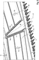
- the representation in Fig. 2 shows a perspective detail V of the cutting unit 1 according to Fig. 1 with the component 14 having a wedge-shaped profile.
- the component 14 is preferably made in one piece.
- An at least two-part embodiment of the component 14 is also conceivable, wherein in a two-part design of the component 14, the two parts with respect to the longitudinal axis LA of the central portion 3 would be constructed in mirror image.
- the component 14 At its outer longitudinal edges 15a or 15b facing the respective conveyor belt 13a, 13b, the component 14 in each case has a laterally outwardly extending section 16a or 16b. These sections 16a, 16b overlap the surface of the respective conveyor belt 13a, 13b in sections.
- the sections 16a, 16b may be curved or have a bevelled, in particular substantially L-shaped, profile. How further from the Fig. 2 can be seen, the component 14 between the outer longitudinal edges 15a and 15b, a flat surface 18 on.
- a sealing element 17 made of an elastic material is arranged on the conveyor belt 13a, 13b facing side of the respective section 16a, 16b.
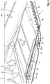
- Fig. 3 is a perspective view of a detail of the cutting mechanism 1 according to Fig. 1 shown with a modified component 19.
- the component 19 differs from that in the Fig. 2 shown component 14 characterized in that it has a roof-shaped surface 20, which is designed sloping to the outer longitudinal edges 15a and 15b.
- the cross-sectional profile of the modified component 19 is essentially triangular.
- the representation in Fig. 4 shows a perspective, partially sectioned partial view of a central portion of the cutting unit according to Fig. 1 , Shown in this view, only the one conveyor belt 13b. Because of the symmetrical structure of the conveying device 5, what is said below applies correspondingly to the conveyor belt 13a, not shown.
- the conveying device 5 comprises pairs of front and rear rollers 23a, 23b arranged in pairs and serving for the drive and the deflection, which surrounds the respective conveyor belt 13a, 13b.
- the rollers 23a, 23b each have an axis 24 which is rotatably mounted in both sides of the conveyor belt 13b arranged bearing points 25.
- the bearings 25 are disposed immediately adjacent to the conveyor belt 13b and the roller 23a, 23b.
- the respective bearing point 25 has a housing which encloses the conveyor belt 13b in sections in the deflection region of the roller 23a, 23b.
- the section of the housing of the bearing 25 enclosing the conveyor belt 13b in the circumferential direction serves as a scraper in order to avoid the entrainment of crop material by the conveyor belt 13b.
- a tensioning device 21 is provided with which the belt tension of the conveyor belt 13b can be adjusted or readjusted by a change in the distance of the rollers 23a, 23b.
- the function of the tensioning device 21 is based on a toggle lever arrangement.
- An operating lever 22 which is in Fig. 4 is shown in a locking position, the operation of the clamping device 21.
- the arrangement the tensioning device 21 is provided between the revolving conveyor belt 13b, which saves space.
- the actuating lever 22 protrudes laterally beyond an outer edge 26 of the conveyor belt 13b on the side facing the wedge-shaped component 14. In this case, the actuating lever 22 extends in the closed position parallel to the conveyor belt 13b.
- the component 14 can be disassembled.
- the thus exposed operating lever 22 is now actuated by an operator to re-tension the conveyor belt 13b.
- a further advantage results from the fact that the tensioning device 21 is built together with the respective conveyor belt 13a, 13b as a unit.
Landscapes
- Life Sciences & Earth Sciences (AREA)
- Environmental Sciences (AREA)
- Zoology (AREA)
- Apparatuses For Bulk Treatment Of Fruits And Vegetables And Apparatuses For Preparing Feeds (AREA)
- Structure Of Belt Conveyors (AREA)
- Threshing Machine Elements (AREA)
Abstract
Description
- Die vorliegende Erfindung betrifft ein Schneidwerk, umfassend einen an einem Grundrahmen angeordneten Mittenabschnitt und wenigstens zwei benachbart zu dem Mittenabschnitt angeordnete Seitenabschnitte, einen sich im Wesentlichen über die Breite des Schneidwerkes erstreckenden Messerbalken sowie zumindest eine hinter dem Messerbalken angeordnete Fördervorrichtung, welche von dem Messerbalken abgeschnittenes Erntegut seitwärts in Richtung des Mittenabschnittes transportiert, welcher wenigstens ein quer zur Transportrichtung der Fördervorrichtung förderndes Fördermittel aufweist.
- Schneidwerke der eingangs genannten Art sind als sogenannte Bandschneidwerke ausgeführt, welche sich durch ein hohes Maß an Flexibilität bei der Anpassung an eine Bodenkontur einer zu bearbeitenden Fläche auszeichnen. Erreicht wird dies durch den Verzicht auf einen in sich starren Schneidwerkstisch, wie er bei Getreideschneidwerken im Allgemeinen üblich ist. Die Seitenabschnitte weisen jeweils zumindest ein endlos umlaufendes, angetriebenes Förderband auf, welches von einer Vielzahl von um eine Drehachse schwenkbaren Tragarmen des jeweiligen Seitenabschnitts getragen wird. Weiterhin sind Bandschneidwerke bekannt, deren Seitenabschnitte und Messerbalken starr ausgeführt sind. Die jeweiligen Förderbänder transportieren mittels des Messerbalkens abgeerntetes Erntegut in seitlicher Richtung, das heißt quer zur Längsachse des Schneidwerks, hin zum Mittenabschnitt. Der Mittenabschnitt verfügt über wenigstens ein quer zur Transportrichtung der Förderbänder förderndes Fördermittel, welches das seitlich zugeführte Erntegut annimmt und umlenkt. Durch eine in dem Grundrahmen vorgesehene Öffnung im Bereich des Mittenabschnittes wird das Erntegut abgefördert und an eine das Schneidwerk tragende Erntemaschine zur weiteren Bearbeitung übergeben.
- Ein gattungsgemäßes Schneidwerk ist aus der
US 6,817,166 B2 bekannt. DieUS 6,817,166 B2 beschreibt ein Schneidwerk mit einem an einem Grundrahmen angeordneten Mittenabschnitt und wenigstens zwei benachbart zu dem Mittenabschnitt angeordneten Seitenabschnitten. Ein sich im Wesentlichen über die Breite des Schneidwerkes erstreckender Messerbalken dient dem Abernten von Erntegut. Hinter dem Messerbalken ist auf dem jeweiligen Seitenabschnitt eine Fördervorrichtung angeordnet, welche das von dem Messerbalken abgeschnittene Erntegut seitwärts in Richtung des Mittenabschnittes transportiert. Der Mittenabschnitt umfasst ein quer zur Transportrichtung der Fördervorrichtung förderndes Fördermittel, welches als endlos umlaufendes Förderband ausgebildet ist. Die Oberfläche des Förderbandes ist mit einer Vielzahl von in Transport bzw. Förderrichtung gesehen paarweise hintereinander angeordneten Leisten versehen. Die jeweils nebeneinander angeordneten Leisten weisen in Transportrichtung des Förderbandes gesehen eine geringfügige Neigung auf. Dabei ist die Anordnung derart gewählt, dass die äußeren, den Außenkanten des Förderbandes zugewandten Enden der Leisten gegenüber den in der Mitte des Förderbandes einander zugewandten Enden in Transportrichtung vorauseilen. Diese Leisten sollen die Gutannahme des von den Förderbändern der Seitenabschnitte an das tieferliegende Förderband des Mittenabschnittes abgegebenen Ernteguts verbessern. - Ausgehend von dem vorstehend genannten Stand der Technik ist es die Aufgabe der vorliegenden Erfindung ein Schneidwerk bereitzustellen, welches sich durch eine verbesserte Gutannahme und Gutabführung im Mittenabschnitt auszeichnet.
- Diese Aufgabe wird erfindungsgemäß durch die kennzeichnenden Merkmale des Anspruches 1 gelöst.
- Vorteilhafte Weiterbildungen sind Gegenstand der Unteransprüche.
- Gemäß dem Anspruch 1 wird vorgeschlagen, dass das Fördermittel zumindest zwei endlos umlaufende Förderbänder umfasst, die unter einem Winkel zur Längsachse des Mittenabschnittes geneigt angeordnet sind. Die geneigte Anordnung der Förderbänder ermöglicht eine Zusammenführung des Erntegutes zur Mitte des Mittenabschnittes hin, so dass sich weniger Erntegut an den Seiten des Mittenabschnitts zurückstaut. Die Übergangsbereiche von den Förderbändern der Seitenabschnitte zu den Förderbändern des Mittenabschnittes werden durch diese Anordnung entlastet, indem das Mitreißen des Ernteguts durch das jeweilige Förderband des angrenzenden Seitenabschnittes zur Unterseite des Schneidwerks hin reduziert wird. Folglich entstehen weniger Schneidwerksverluste. Die Gefahr von Blockaden durch sich aufstauendes Erntegut im Übergangsbereich wird ebenfalls deutlich verringert. Das Erntegut tendiert dazu, in dem Übergangsbereich zwischen den seitwärts umlaufenden Förderbändern und dem quer dazu umlaufenden, tiefergelegenen Förderband eingeklemmt zu werden, was zu einer Blockade des Schneidwerkes führt. Die erfindungsgemäße Anordnung zumindest zweier Förderbänder auf dem Mittenabschnitt führt dazu, dass das von den Seitenabschnitten kommende Erntegut bei der Gutannahme durch die Förderbänder des Mittenabschnittes nicht nahezu rechtwinklig umgelenkt wird, wie dies bei dem Schneidwerk gemäß der
US 6,817,166 B2 der Fall ist. Ein weiterer Nachteil des aus derUS 6,817,166 B2 bekannten Förderbandes im Mittenbereich ergibt sich aus der zur Förderrichtung geneigten Anordnung der Leisten auf der Förderbandoberfläche. Die Neigung der Leisten bezüglich der Längsachse der Fördervorrichtung kann nur sehr gering ausgeführt sein, da es ansonsten im Bereich der Antriebs- und Umlenkrollen zu Problemen kommt, die zu einer Beschädigung des Förderbandes führen. Denkbar ist auch eine Anordnung zumindest eines weiteren Förderbandes im Mittenbereich des Schneidwerkes, welches zwischen den geneigt angeordnet Förderbändern angeordnet ist. - Bevorzugt sind die zumindest zwei Förderbänder im Wesentlichen V-förmig angeordnet, wobei die Förderbänder in Transportrichtung zusammenlaufen. Dabei schließen die beiden Förderbänder des Mittenabschnittes jeweils den gleichen Winkel mit der Längsachse ein.
- Gemäß einer vorteilhaften Weiterbildung kann vorgesehen sein, dass ausgehend vom Messerbalken sich ein einen in seiner Längserstreckung im Wesentlichen keilförmigen Verlauf aufweisendes Bauteil zwischen den Förderbändern erstreckt. Das keilförmige Bauteil deckt den Bereich zwischen den bezüglich der Längsachse des Mittenabschnittes geneigt angeordneten Förderbändern zumindest teilweise ab. Die Oberfläche des keilförmigen Bauteils kann sich zumindest abschnittsweise auf einer Höhe mit der Oberseite der Förderbänder befinden. Dadurch lassen sich ungewollte Ablagerungen von Erntegut auf der Oberfläche des keilförmigen Bauteils zumindest minimieren.
- Weiterhin kann das Bauteil einen sich in Transportrichtung der Förderbänder verjüngenden Verlauf aufweisen. Das keilförmige Bauteil sollte im Wesentlichen an den Verlauf der Anordnung der Förderbänder im Mittenabschnitt angepasst sein. Dadurch können offene Bereiche zwischen den Förderbändern im Mittenabschnitt vermieden werden. Auf diese Weise kann das Hindurchtreten von Erntegut insbesondere zwischen die endlos umlaufenden Förderbänder verhindert werden.
- Einer vorteilhaften Ausgestaltung zufolge kann das keilförmige Bauteil eine dachförmige Oberfläche aufweisen, welche zu das Bauteil begrenzenden Außenlängskanten hin abfallend ausgeführt ist. Insbesondere kann das keilförmige Bauteil einen dreieckförmigen Querschnitt aufweisen. Hierdurch kann eine Art Abstreifeffekt erreicht werden, da aufgrund der spitz zulaufenden Seitenflächen des keilförmigen Bauteiles das Ablagern oder Anhäufen von Erntegut zumindest erschwert wird. Im Mittenbereich zwischen den Förderbändern vom Schneidwerk aufgenommenes Erntegut gelangt somit in den Annahmebereich zumindest eines der beiden Förderbänder.
- Bevorzugt kann das keilförmige Bauteil an seinen dem jeweiligen Förderband zugewandten Außenlängskanten einen sich nach außen erstreckenden Abschnitt aufweisen, welcher die Oberfläche des jeweiligen Förderbandes abschnittsweise überlappt. Der, insbesondere konvexe, Abschnitt dient der Abdichtung des jeweils benachbart angeordneten Förderbandes, um zu verhindern, dass Erntegut zwischen das jeweilige endlos umlaufende Förderband gelangen kann. Der jeweilige Abschnitt kann auch ein im Wesentlichen L-förmiges Profil aufweisen.
- Um eine verschleißarme Abdichtung an der Außenlängskante des jeweiligen Abschnittes gegenüber dem überlappten Förderbandabschnitt zu erreichen, kann hierfür zumindest ein aus einem elastischen Material hergestelltes Dichtelement an der dem Förderband zugewandten Seite des jeweiligen Abschnittes angeordnet sein. Das Dichtelement liegt dabei auf der Oberfläche des Förderbandes auf.
- Weiterhin kann das Bauteil lösbar an einem Rahmenbauteil des Mittenabschnittes montiert sein. Hierdurch ist eine einfache Austauschbarkeit des keilförmigen Bauteils gewährleistet. Zudem ist eine einfache Zugänglichkeit zu den benachbart zu dem keilförmigen Bauteil angeordneten Förderbändern im Mittenabschnitt gegeben.
- Insbesondere kann das jeweilige Förderband zwei parallel zueinander angeordneten Rollen sowie eine zwischen den Rollen angeordnete Spannvorrichtung zur Anpassung des Abstandes der Rollen abschnittsweise umgeben. Durch diese Anordnung der Spannvorrichtung zwischen dem umlaufenden Förderband lässt sich eine bauraumsparende Unterbringung erzielen.
- Hierbei kann die Spannvorrichtung einen Betätigungshebel aufweisen, der auf der dem keilförmigen Element zugewandten Seite seitlich über die Außenkante des Förderbandes abschnittsweise hinausragt und sich in einer Verschlussstellung parallel zum Förderband erstreckt.
- Eine bevorzugte Weiterbildung kann sein, dass die Förderbänder des Mittenabschnitts unabhängig voneinander antreibbar sind. Mittels einer geeigneten Überwachung der von den Seitenabschnitten des Schneidwerks aufgenommenen Erntegutmengen und einer Ansteuerung der jeweiligen Aktorik der Förderbänder lässt sich auf temporäre Schwankungen bei der Gutannahme durch die Förderbänder im Mittenabschnitt reagieren.
- Die vorliegende Erfindung wird nachstehend anhand eines in den Zeichnungen dargestellten Ausführungsbeispieles näher erläutert.
- Es zeigen:
- Fig. 1
- eine schematische Teilansicht eines Schneidwerkes in Draufsicht;
- Fig. 2
- eine perspektivische Detailansicht V des Schneidwerkes gemäß
Fig. 1 mit einem einen keilförmigen Verlauf aufweisenden Bauteil; - Fig. 3
- eine perspektivische Ansicht eines Details des Schneidwerkes gemäß
Fig. 1 mit einem modifizierten Bauteil; - Fig. 4
- eine perspektivische, teilweise geschnittene Teilansicht eines Mittenabschnittes des Schneidwerks gemäß
Fig. 1 . - In
Fig. 1 ist eine schematische Teilansicht eines Schneidwerkes 1 in Draufsicht dargestellt. Das Schneidwerk 1 ist als ein so genanntes Bandschneidwerk ausgeführt, welches sich durch ein hohes Maß an Flexibilität bei der Anpassung an eine Bodenkontur einer zu bearbeitenden respektive abzuerntenden Fläche aufweist. Das Schneidwerk 1 weist einen Grundrahmen 2 auf, an welchem ein Mittenabschnitt 3 und zumindest zwei benachbart zu dem Mittenabschnitt 3 angeordnete Seitenabschnitte 4 angeordnet sind. An dem Mittenabschnitt 3 und den Seitenabschnitten 4 ist auf der dem Grundrahmen 2 gegenüberliegenden Vorderseite ein Messerbalken 6 angeordnet, der sich im Wesentlichen über die gesamte Breite des Schneidwerkes 1 erstreckt. Weiterhin sind an dem Grundrahmen 2 des Schneidwerkes 1 nicht dargestellte Haspeln angeordnet, die sich über die Breite eines Seitenabschnittes 4 sowie teilweise über die Breite des Mittenabschnittes 3 erstrecken. Die Haspeln dienen der Verbesserung der Annahme des Erntegutes durch den Messerbalken 6. - Das von dem Messerbalken 6 abgetrennte Erntegut wird einer hinter dem Messerbalken 6 angeordneten Fördervorrichtung 5 zugeführt, die auf den jeweiligen Seitenabschnitten 4 mindestens ein endlos umlaufendes Seitenförderband 7 umfasst. Die endlos umlaufenden Seitenförderbänder 7 sind benachbart zu dem Mittenabschnitt 3 angeordnet, um das von dem Messerbalken 6 abgeschnittene Erntegut parallel zu der Längsachse des Schneidwerkes 1 in Richtung des Mittenabschnittes 3 zu transportieren. Im Bereich des Mittenabschnittes 3 wird das Erntegut einer Einzugsvorrichtung 8 zugeführt. Die Einzugsvorrichtung 8 ist als eine antreibbare Einzugswalze 9, die durch Rahmenelemente an dem Grundrahmen 2 gelagert ist, ausgeführt. Die Einzugswalze 9 weist einziehbare Finger 10 auf. Die Einzugsvorrichtung 8 führt das von den endlosen Förderbändern 7 dem Mittenabschnitt 3 seitlich zugeführte Erntegut einer in dem Grundrahmen 2 vorgesehenen, hinter der Einzugswalze 9 befindlichen, Öffnung zu, durch welche das abgeschnittene Erntegut durch einen lediglich andeutungsweise dargestellten Einzugskanal 11 eines Mähdreschers, an dem das Schneidwerk 1 befestigbar ist, dem Mähdrescher zur weiteren Verarbeitung übergeben wird.
- Der Mittenabschnitt 3 weist ein Fördermittel 12 auf, welches zumindest zwei endlos umlaufende Förderbänder 13a, 13b umfasst. Mit dem Bezugszeichen TR gekennzeichnete Pfeile deuten die Transport- bzw. Förderrichtung der Förderbänder 13a, 13b an. Die beiden Förderbänder 13a, 13b sind zu einer Längsachse LA des Mittenabschnittes 3 geneigt angeordnet. Die benachbart auf den Seitenabschnitten 4 angeordneten Seitenförderbänder 7 überlappen das jeweilige Förderband 13a, 13b abschnittsweise. Die Anordnung der Förderbänder 13a, 13b ist derart gewählt, dass diese im Wesentlichen V-förmig ist. Dazu sind die beiden Förderbänder 13a, 13b in Transportrichtung TR aufeinander zulaufend angeordnet. Dabei schließt das jeweilige Förderband 13a, 13b mit der Längsachse des Mittenabschnittes 3 einen Winkel α ein, der größer oder gleich 5° beträgt. Diese Anordnung hat den Vorteil, dass das von den Seitenförderbändern 7 kommende Erntegut nicht, wie es aus dem Stand der Technik bekannt ist, beim Übergang auf den Mittenbereich um einen Winkel von 90° umgelenkt werden muss. Die V-förmige Anordnung der Förderbänder 13a, 13b führt zu einer Zusammenführung des Erntegutes in den Mittenbereich des Mittenabschnittes 3, sodass ein Zurückstauen von Erntegut auf dem Mittenabschnitt 3 zu den Seitenförderbändern 7 hin reduziert wird.
- Zwischen den Förderbändern 13a, 13b des Mittenabschnittes 3 ist ein einen in seiner Längsrichtung im Wesentlichen keilförmigen Verlauf aufweisendes Bauteil 14 angeordnet. Das Bauteil 14 weist einen sich in Transportrichtung TR der Förderbänder 13a, 13b verjüngenden Verlauf auf. Hierbei erstreckt sich das Bauteil 14 im Wesentlichen zwischen den beiden Förderbändern 13a, 13b, so dass die aufgrund der geneigten Anordnung der beiden Förderbänder 13a, 13b freibleibende Fläche abgedeckt ist. Denkbar ist auch die Anordnung eines weiteren Förderbandes zwischen den beiden V-förmig angeordneten Förderbändern 13a, 13b.
- Die Darstellung in
Fig. 2 zeigt eine perspektivische Detailansicht V des Schneidwerkes 1 gemäßFig. 1 mit dem einen keilförmigen Verlauf aufweisenden Bauteil 14. Das Bauteil 14 ist vorzugsweise einteilig ausgeführt. Eine zumindest zweiteilige Ausgestaltung des Bauteils 14 ist ebenfalls denkbar, wobei bei einer zweiteiligen Ausführung des Bauteils 14 die beiden Teile bezüglich der Längsachse LA des Mittenabschnittes 3 spiegelbildlich aufgebaut wären. An seinen dem jeweiligen Förderband 13a, 13b zugewandten Außenlängskanten 15a bzw. 15b weist das Bauteil 14 jeweils einen sich seitlich nach außen erstreckenden Abschnitt 16a bzw. 16b auf. Diese Abschnitte 16a, 16b überlappen die Oberfläche des jeweiligen Förderbandes 13a, 13b abschnittsweise. Dabei können die Abschnitte 16a, 16b gewölbt ausgebildet sein oder ein abgekantetes, insbesondere im Wesentlichen L-förmiges, Profil aufweisen. Wie weiter aus derFig. 2 ersichtlich ist, weist das Bauteil 14 zwischen den Außenlängskanten 15a bzw. 15b eine ebene Oberfläche 18 auf. Auf der dem Förderband 13a, 13b zugewandten Seite des jeweiligen Abschnittes 16a, 16b ist ein aus einem elastischen Material bestehendes Dichtelement 17 angeordnet. - In
Fig. 3 ist eine perspektivische Ansicht eines Details des Schneidwerkes 1 gemäßFig. 1 mit einem modifizierten Bauteil 19 dargestellt. Das Bauteil 19 unterscheidet sich von dem in derFig. 2 gezeigten Bauteil 14 dadurch, dass es eine dachförmige Oberfläche 20 aufweist, welche zu den Außenlängskanten 15a bzw. 15b abfallend ausgeführt ist. Der Querschnittsverlauf des modifizierten Bauteils 19 ist dabei im Wesentlichen dreieckförmig ausgebildet. - Die Darstellung in
Fig. 4 zeigt eine perspektivische, teilweise geschnittene Teilansicht eines Mittenabschnittes des Schneidwerks gemäßFig. 1 . Dargestellt ist in dieser Ansicht nur das eine Förderband 13b. Wegen des symmetrischen Aufbaus der Fördervorrichtung 5 gilt das nachstehend Gesagte entsprechend für das nicht dargestellte Förderband 13a. Die Fördervorrichtung 5 umfasst jeweils paarweise angeordnete, dem Antrieb und der Umlenkung dienende vordere und hintere Rollen 23a, 23b, welche das jeweilige Förderband 13a, 13b umschließt. Die Rollen 23a, 23b weisen jeweils eine Achse 24 auf, welche drehbar in beidseitig des Förderbandes 13b angeordneten Lagerstellen 25 gelagert ist. Die Lagerstellen 25 sind unmittelbar benachbart zu dem Förderband 13b bzw. der Rolle 23a, 23b angeordnet. Die jeweilige Lagerstelle 25 weist ein Gehäuse auf, welches das Förderband 13b im Umlenkbereich der Rolle 23a, 23b abschnittsweise umschließt. Der das Förderband 13b in Umfangsrichtung umschließende Abschnitt des Gehäuses der Lagerstelle 25 dient dabei als Abstreifer, um das Mitführen von Erntematerial durch das Förderband 13b zu vermeiden. - Weiterhin ist aus der Darstellung in
Fig. 4 ersichtlich, dass eine Spannvorrichtung 21 vorgesehen ist, mit der die Bandspannung des Förderbandes 13b durch eine Abstandsänderung der Rollen 23a, 23b angepasst beziehungsweise nachgestellt werden kann. Die Funktion der Spannvorrichtung 21 basiert auf einer Kniehebelanordnung. Ein Betätigungshebel 22, der inFig. 4 in einer Verriegelungsstellung dargestellt ist, dient der Betätigung der Spannvorrichtung 21. Die Anordnung der Spannvorrichtung 21 ist zwischen dem umlaufenden Förderband 13b vorgesehen, was bauraumsparend ist. Der Betätigungshebel 22 ragt auf der dem keilförmigen Bauteil 14 zugewandten Seite seitlich über eine Außenkante 26 des Förderbandes 13b abschnittsweise hinaus. Dabei erstreckt sich der Betätigungshebel 22 in der Verschlussstellung parallel zum Förderband 13b. Um das jeweilige Förderband 13a, 13b nachspannen zu können, lässt sich das Bauteil 14 demontieren. Der dadurch freiliegende Betätigungshebel 22 ist nunmehr durch eine Bedienperson betätigbar, um das Förderband 13b nachzuspannen. Ein weiterer Vorteil ergibt sich daraus, dass die Spannvorrichtung 21 zusammen mit dem jeweiligen Förderband 13a, 13 b als eine Einheit erbaut wird.Bezugszeichenliste 1 Schneidwerk α Winkel 2 Grundrahmen 3 Mittenabschnitt 4 Seitenabschnitte 5 Fördervorrichtung 6 Messerbalken 7 Seitenförderband 8 Einzugsvorrichtung 9 Einzugswalze 10 Einziehbare Finger 11 Einzugskanal 12 Fördermittel 13a Förderband 13b Förderband 14 Bauteil 15a Außenlängskante 15b Außenlängskante 16a Äußerer Abschnitt 16b Äußerer Abschnitt 17 Dichtelement 18 Ebene Oberfläche 19 Bauteil 20 Dachförmige Oberfläche 21 Spannvorrichtung 22 Betätigungshebel 23 Rollen 24 Achse 25 Lagerstelle 26 Außenkante TR Transportrichtung LA Längsachse
Claims (11)
- Schneidwerk (1), umfassend einen an einem Grundrahmen (2) angeordneten Mittenabschnitt (3) und wenigstens zwei benachbart zu dem Mittenabschnitt (3) angeordnete Seitenabschnitte (4), einen sich im Wesentlichen über die Breite des Schneidwerkes (1) erstreckenden Messerbalken (6) sowie zumindest eine hinter dem Messerbalken (6) angeordnete Fördervorrichtung (5), welche von dem Messerbalken (6) abgeschnittenes Erntegut seitwärts in Richtung des Mittenabschnittes (3) transportiert, welcher wenigstens ein quer zur Transportrichtung der Fördervorrichtung (5) förderndes Fördermittel (12) aufweist, dadurch gekennzeichnet, dass das Fördermittel (12) zumindest zwei endlos umlaufende Förderbänder (13a, 13b) umfasst, die unter einem Winkel (α) zur Längsachse (LA) des Mittenabschnittes (3) geneigt angeordnet sind.
- Schneidwerk (1) nach Anspruch 1, dadurch gekennzeichnet, dass die zumindest zwei Förderbänder (13a, 13b) im Wesentlichen V-förmig angeordnet sind.
- Schneidwerk nach einem der vorangehenden Ansprüche, dadurch gekennzeichnet, dass ausgehend vom Messerbalken (6) sich ein einen in seiner Längserstreckung im Wesentlichen keilförmigen Verlauf aufweisendes Bauteil (14, 19) zwischen den Förderbändern (13a, 13b) erstreckt.
- Schneidwerk nach einem der vorangehenden Ansprüche, dadurch gekennzeichnet, dass das keilförmige Bauteil (14, 19) einen sich in Transportrichtung (TR) verjüngenden Verlauf aufweist.
- Schneidwerk nach einem der vorangehenden Ansprüche, dadurch gekennzeichnet, dass das keilförmige Bauteil (19) eine dachförmige Oberfläche (20) aufweist, welche zu das Bauteil (19) begrenzenden Außenlängskanten (15a bzw. 15b) abfallend ausgeführt ist.
- Schneidwerk nach einem der vorangehenden Ansprüche, dadurch gekennzeichnet, dass das keilförmige Bauteil (14, 19) an seinen dem jeweiligen Förderband (13a, 13b) zugewandten Außenlängskanten (15a, 15b) einen sich seitlich nach außen erstreckenden Abschnitt (16a, 16b) aufweist, welcher die Oberfläche des jeweiligen Förderbandes (13a, 13b) abschnittsweise überlappt.
- Schneidwerk nach einem der vorangehenden Ansprüche, dadurch gekennzeichnet, dass zumindest ein aus einem elastischen Material hergestelltes Dichtelement (17) an der dem Förderband (13a, 13b) zugewandten Seite des jeweiligen Abschnittes (16a, 16b) angeordnet ist.
- Schneidwerk (1) nach einem der vorangehenden Ansprüche, dadurch gekennzeichnet, dass das keilförmige Bauteil (14, 19) lösbar an einem Rahmenbauteil des Mittenabschnittes (3) montiert ist.
- Schneidwerk (1) nach einem der vorangehenden Ansprüche, dadurch gekennzeichnet, dass das jeweilige Förderband (13a, 13b) zwei parallel zueinander angeordnete Rollen (23a, 23b) sowie eine zwischen den Rollen (23a, 23b) angeordnete Spannvorrichtung (21) zur Anpassung des Abstandes der Rollen (23a, 23b) abschnittsweise umgibt.
- Schneidwerk (1) nach einem der vorangehenden Ansprüche, dadurch gekennzeichnet, dass die Spannvorrichtung (21) einen Betätigungshebel (22) aufweist, der auf der dem keilförmigen Bauteil (14, 19) zugewandten Seite seitlich über die Außenkante (26) des Förderbandes (13a, 13b) abschnittsweise hinausragt und sich in einer Verschlussstellung parallel zum Förderband (13a, 13b) erstreckt.
- Schneidwerk (1) nach einem der vorangehenden Ansprüche, dadurch gekennzeichnet, dass die Förderbänder (13a, 13b) des Mittenabschnitts (3) unabhängig voneinander antreibbar sind.
Applications Claiming Priority (1)
| Application Number | Priority Date | Filing Date | Title |
|---|---|---|---|
| DE102016118174.9A DE102016118174A1 (de) | 2016-09-26 | 2016-09-26 | Schneidwerk |
Publications (2)
| Publication Number | Publication Date |
|---|---|
| EP3298879A1 true EP3298879A1 (de) | 2018-03-28 |
| EP3298879B1 EP3298879B1 (de) | 2020-11-18 |
Family
ID=58638737
Family Applications (1)
| Application Number | Title | Priority Date | Filing Date |
|---|---|---|---|
| EP17168329.5A Active EP3298879B1 (de) | 2016-09-26 | 2017-04-27 | Schneidwerk |
Country Status (6)
| Country | Link |
|---|---|
| US (1) | US10470370B2 (de) |
| EP (1) | EP3298879B1 (de) |
| AR (1) | AR108515A1 (de) |
| BR (1) | BR102017014639B1 (de) |
| DE (1) | DE102016118174A1 (de) |
| HU (1) | HUE053365T2 (de) |
Cited By (5)
| Publication number | Priority date | Publication date | Assignee | Title |
|---|---|---|---|---|
| EP3434095A1 (de) * | 2017-07-27 | 2019-01-30 | Macdon Industries Ltd. | Vorsatz für eine erntemaschine |
| DE102018116213A1 (de) | 2018-07-04 | 2020-01-09 | CLAAS Hungária Kft. | Schneidwerk für eine landwirtschaftliche Arbeitsmaschine sowie Verfahren zu dessen Bedienung |
| DE102018116232A1 (de) | 2018-07-04 | 2020-01-09 | Claas Hungaria Kft. | Schneidwerk für eine landwirtschaftliche Arbeitsmaschine sowie Verfahren zur Einstellung eines Schneidwerks |
| US11445655B2 (en) | 2018-07-04 | 2022-09-20 | CLAAS Hungária Kft. | Cutting unit for an agricultural working machine, and method for adjusting a cutting unit |
| EP4356713A1 (de) | 2022-10-20 | 2024-04-24 | Deere & Company | Erntevorsatz zur ganzpflanzenernte |
Families Citing this family (12)
| Publication number | Priority date | Publication date | Assignee | Title |
|---|---|---|---|---|
| US11317563B2 (en) * | 2017-02-24 | 2022-05-03 | IP Machinery Pty Ltd | Feeder device for a draper header |
| US10426088B2 (en) * | 2017-10-11 | 2019-10-01 | Deere & Company | Center feed assembly for a draper |
| US10537063B2 (en) | 2017-10-11 | 2020-01-21 | Deere & Company | Folding agricultural head |
| US10433486B2 (en) | 2017-10-16 | 2019-10-08 | Deere & Company | System and method for wing float on a combine draper header |
| US10568266B2 (en) | 2017-10-17 | 2020-02-25 | Deere & Company | Self-contained combine draper wing leveler |
| US10820515B2 (en) * | 2018-06-28 | 2020-11-03 | Deere & Company | Combine header with feed assist bulky crop auger on a draper platform |
| EP3603375B1 (de) * | 2018-07-31 | 2021-03-31 | CNH Industrial Belgium N.V. | Einlaufbandförderer an einem mähdreschereinzug |
| DE102020121773A1 (de) | 2020-08-19 | 2022-02-24 | Claas Selbstfahrende Erntemaschinen Gmbh | Seitenschneidwerk |
| US12453312B2 (en) * | 2021-06-16 | 2025-10-28 | Deere & Company | Agricultural header with inter-belt crop divider |
| DE102022116765A1 (de) * | 2022-07-05 | 2024-01-11 | Claas Hungaria Kft. | Bandschneidwerk |
| US20250204324A1 (en) * | 2023-12-21 | 2025-06-26 | Agco Corporation | Draper Belt Tensioner System |
| DE102024119143A1 (de) * | 2024-07-05 | 2026-01-08 | Claas Selbstfahrende Erntemaschinen Gmbh | Fördereinrichtung zur Verwendung in einem Schneidwerk einer landwirtschaftlichen Erntemaschine sowie Schneidwerk und Erntemaschine |
Citations (4)
| Publication number | Priority date | Publication date | Assignee | Title |
|---|---|---|---|---|
| US5464371A (en) * | 1993-12-06 | 1995-11-07 | Honey Bee Manufacturing Ltd. | Feeder adapter for mounting a combine header to a feeder housing of a combine |
| US6817166B2 (en) | 2003-07-11 | 2004-11-16 | Macdon Industriesltd. | Crop feed draper for a header |
| US20080295474A1 (en) * | 2007-06-04 | 2008-12-04 | Claas Selbstfahrende Erntemaschinen Gmbh | Central auger crop feed system for a harvester |
| US7823372B1 (en) * | 2009-06-22 | 2010-11-02 | Deere & Company | Skewed roller conveyor for double windrow attachment |
Family Cites Families (18)
| Publication number | Priority date | Publication date | Assignee | Title |
|---|---|---|---|---|
| US2608041A (en) * | 1947-01-24 | 1952-08-26 | Case Co J I | Conveying means for harvester headers |
| US5822959A (en) * | 1996-05-06 | 1998-10-20 | Norton; R. Scott | Pick-up for harvesting a lying crop |
| US6202397B1 (en) * | 1999-05-27 | 2001-03-20 | Deere & Company | Draper belt tensioning mechanism for a harvesting platform |
| US6865871B2 (en) * | 2003-07-14 | 2005-03-15 | Macdon Industries Ltd. | Crop feed arrangement for the header of a combine harvester |
| US7392646B2 (en) * | 2004-06-16 | 2008-07-01 | Macdon Industries Ltd. | Reversible feed roller with radially extendible fingers |
| DE102005021766A1 (de) * | 2005-05-11 | 2006-11-16 | Deere & Company, Moline | Schneidwerk mit Fördergurtzusammenbauten |
| US20070193243A1 (en) * | 2006-02-10 | 2007-08-23 | Schmidt James R | Combine Harvester Draper Header Having Flexible Cutterbar |
| CA2564777C (en) * | 2006-10-20 | 2010-08-03 | Macdon Industries Ltd. | Crop header with draper canvas and a seal with an element of the cutter bar |
| CA2572274C (en) * | 2006-12-29 | 2014-05-27 | Honey Bee Manufacturing Ltd. | Rock trap for combine header |
| US8281561B2 (en) * | 2010-08-17 | 2012-10-09 | Deere & Company | Flexible draper belt drive for an agricultural harvesting machine |
| DE102010037131A1 (de) * | 2010-08-24 | 2012-03-01 | Claas Selbstfahrende Erntemaschinen Gmbh | Schneidwerk |
| DE102013100322A1 (de) * | 2013-01-14 | 2014-07-17 | Claas Selbstfahrende Erntemaschinen Gmbh | Schneidwerk |
| DE102013103381A1 (de) * | 2013-04-04 | 2014-10-09 | Claas Selbstfahrende Erntemaschinen Gmbh | Schneidwerk |
| DE102014216112A1 (de) * | 2014-08-13 | 2016-02-18 | Walter Schmid | Selbstfahrende Erntemaschine |
| US9788486B2 (en) * | 2014-12-30 | 2017-10-17 | Agco Corporation | Grain header with swathing and chopping capability |
| US20160360699A1 (en) * | 2015-06-10 | 2016-12-15 | Jose Luis Allochis | Conveyor belt tensing apparatus for a harvesting header |
| DE102015118143A1 (de) * | 2015-10-23 | 2017-04-27 | Arnold Jäger Holding GmbH | Nockenriemen, insbesondere für landwirtschaftliche Maschinen |
| BE1023925B1 (nl) * | 2016-03-01 | 2017-09-13 | Cnh Industrial Belgium Nv | Toevoertoestel voor maaidorser |
-
2016
- 2016-09-26 DE DE102016118174.9A patent/DE102016118174A1/de not_active Withdrawn
-
2017
- 2017-04-27 HU HUE17168329A patent/HUE053365T2/hu unknown
- 2017-04-27 EP EP17168329.5A patent/EP3298879B1/de active Active
- 2017-05-17 AR ARP170101333A patent/AR108515A1/es active IP Right Grant
- 2017-07-06 BR BR102017014639-1A patent/BR102017014639B1/pt active IP Right Grant
- 2017-08-08 US US15/671,726 patent/US10470370B2/en active Active
Patent Citations (4)
| Publication number | Priority date | Publication date | Assignee | Title |
|---|---|---|---|---|
| US5464371A (en) * | 1993-12-06 | 1995-11-07 | Honey Bee Manufacturing Ltd. | Feeder adapter for mounting a combine header to a feeder housing of a combine |
| US6817166B2 (en) | 2003-07-11 | 2004-11-16 | Macdon Industriesltd. | Crop feed draper for a header |
| US20080295474A1 (en) * | 2007-06-04 | 2008-12-04 | Claas Selbstfahrende Erntemaschinen Gmbh | Central auger crop feed system for a harvester |
| US7823372B1 (en) * | 2009-06-22 | 2010-11-02 | Deere & Company | Skewed roller conveyor for double windrow attachment |
Cited By (6)
| Publication number | Priority date | Publication date | Assignee | Title |
|---|---|---|---|---|
| EP3434095A1 (de) * | 2017-07-27 | 2019-01-30 | Macdon Industries Ltd. | Vorsatz für eine erntemaschine |
| DE102018116213A1 (de) | 2018-07-04 | 2020-01-09 | CLAAS Hungária Kft. | Schneidwerk für eine landwirtschaftliche Arbeitsmaschine sowie Verfahren zu dessen Bedienung |
| DE102018116232A1 (de) | 2018-07-04 | 2020-01-09 | Claas Hungaria Kft. | Schneidwerk für eine landwirtschaftliche Arbeitsmaschine sowie Verfahren zur Einstellung eines Schneidwerks |
| US11445655B2 (en) | 2018-07-04 | 2022-09-20 | CLAAS Hungária Kft. | Cutting unit for an agricultural working machine, and method for adjusting a cutting unit |
| EP4356713A1 (de) | 2022-10-20 | 2024-04-24 | Deere & Company | Erntevorsatz zur ganzpflanzenernte |
| DE102022127703A1 (de) | 2022-10-20 | 2024-04-25 | Deere & Company | Erntevorsatz zur Ganzpflanzenernte |
Also Published As
| Publication number | Publication date |
|---|---|
| AR108515A1 (es) | 2018-08-29 |
| EP3298879B1 (de) | 2020-11-18 |
| BR102017014639B1 (pt) | 2022-03-29 |
| BR102017014639A2 (pt) | 2018-04-10 |
| US10470370B2 (en) | 2019-11-12 |
| DE102016118174A1 (de) | 2018-03-29 |
| US20180084724A1 (en) | 2018-03-29 |
| HUE053365T2 (hu) | 2021-06-28 |
Similar Documents
| Publication | Publication Date | Title |
|---|---|---|
| EP3298879B1 (de) | Schneidwerk | |
| DE2848451C2 (de) | ||
| DE2245602C2 (de) | Zwischen Mäh- und Dreschwerk eines Mähdreschers angeordnete Zuführungseinrichtung für Erntegut | |
| EP3406129B1 (de) | Schneidwerk | |
| EP1483955B1 (de) | Erntegerät | |
| DE2536028B2 (de) | Erntevorrichtung für stengeiförmiges Halmgut | |
| DE1507195C3 (de) | Erntemaschine für stengeliges Halmgut, insbesondere Mais | |
| DE10108516A1 (de) | Maschine zum Mähen von stängelartigem Erntegut | |
| DE10028887A1 (de) | Einzugs- und Pflückeinrichtung | |
| EP2786650A1 (de) | Schneidwerk | |
| DE3115723C2 (de) | Vorsatzgerät für eine Maiserntemaschine | |
| EP1177718B1 (de) | Maschine zum Mähen von stängelartingen Erntegut | |
| DE2735784A1 (de) | Reihen-schneidvorsatz fuer feldhaecksler | |
| EP2923556B1 (de) | Vorsatzgerät für einen selbstfahrenden Mähdrescher zum Ernten von Mais | |
| DE102021112099A1 (de) | Korbsegment und Korb für einen Mähdrescher | |
| EP2430900B1 (de) | Vorsatzgerät | |
| DE19750954A1 (de) | Aufnahmeeinrichtung einer landwirtschaftlichen Erntemaschine | |
| EP4074162B1 (de) | Rundballenpresse mit starterwalze und elastisch auslenkbarem auslenkelement | |
| DE19952566C1 (de) | Erntegerät | |
| EP4309489B1 (de) | Bandschneidwerk | |
| EP4305951B1 (de) | Bandschneidwerk | |
| DE102008021784A1 (de) | Erntemaschine mit Schrägförderer | |
| EP4070642A1 (de) | Vorsatzgerät zum ernten stängelartiger pflanzen mit einem quer zur fahrtrichtung liegenden pflückspalt | |
| DE3324898A1 (de) | Schneid- und zufuehreinrichtung fuer eine gezogene oder fuer den dreipunktanbau am schlepper vorgesehene maschine zum ernten von mais o.dgl. stengelartigem erntegut | |
| EP1543713B1 (de) | Erntegerät |
Legal Events
| Date | Code | Title | Description |
|---|---|---|---|
| PUAI | Public reference made under article 153(3) epc to a published international application that has entered the european phase |
Free format text: ORIGINAL CODE: 0009012 |
|
| STAA | Information on the status of an ep patent application or granted ep patent |
Free format text: STATUS: THE APPLICATION HAS BEEN PUBLISHED |
|
| AK | Designated contracting states |
Kind code of ref document: A1 Designated state(s): AL AT BE BG CH CY CZ DE DK EE ES FI FR GB GR HR HU IE IS IT LI LT LU LV MC MK MT NL NO PL PT RO RS SE SI SK SM TR |
|
| AX | Request for extension of the european patent |
Extension state: BA ME |
|
| STAA | Information on the status of an ep patent application or granted ep patent |
Free format text: STATUS: REQUEST FOR EXAMINATION WAS MADE |
|
| 17P | Request for examination filed |
Effective date: 20180928 |
|
| RBV | Designated contracting states (corrected) |
Designated state(s): AL AT BE BG CH CY CZ DE DK EE ES FI FR GB GR HR HU IE IS IT LI LT LU LV MC MK MT NL NO PL PT RO RS SE SI SK SM TR |
|
| GRAP | Despatch of communication of intention to grant a patent |
Free format text: ORIGINAL CODE: EPIDOSNIGR1 |
|
| STAA | Information on the status of an ep patent application or granted ep patent |
Free format text: STATUS: GRANT OF PATENT IS INTENDED |
|
| INTG | Intention to grant announced |
Effective date: 20200825 |
|
| GRAS | Grant fee paid |
Free format text: ORIGINAL CODE: EPIDOSNIGR3 |
|
| GRAA | (expected) grant |
Free format text: ORIGINAL CODE: 0009210 |
|
| STAA | Information on the status of an ep patent application or granted ep patent |
Free format text: STATUS: THE PATENT HAS BEEN GRANTED |
|
| AK | Designated contracting states |
Kind code of ref document: B1 Designated state(s): AL AT BE BG CH CY CZ DE DK EE ES FI FR GB GR HR HU IE IS IT LI LT LU LV MC MK MT NL NO PL PT RO RS SE SI SK SM TR |
|
| REG | Reference to a national code |
Ref country code: GB Ref legal event code: FG4D Free format text: NOT ENGLISH |
|
| REG | Reference to a national code |
Ref country code: CH Ref legal event code: EP |
|
| REG | Reference to a national code |
Ref country code: IE Ref legal event code: FG4D Free format text: LANGUAGE OF EP DOCUMENT: GERMAN |
|
| REG | Reference to a national code |
Ref country code: DE Ref legal event code: R096 Ref document number: 502017008224 Country of ref document: DE |
|
| REG | Reference to a national code |
Ref country code: AT Ref legal event code: REF Ref document number: 1334726 Country of ref document: AT Kind code of ref document: T Effective date: 20201215 |
|
| REG | Reference to a national code |
Ref country code: NL Ref legal event code: MP Effective date: 20201118 |
|
| PG25 | Lapsed in a contracting state [announced via postgrant information from national office to epo] |
Ref country code: NO Free format text: LAPSE BECAUSE OF FAILURE TO SUBMIT A TRANSLATION OF THE DESCRIPTION OR TO PAY THE FEE WITHIN THE PRESCRIBED TIME-LIMIT Effective date: 20210218 Ref country code: RS Free format text: LAPSE BECAUSE OF FAILURE TO SUBMIT A TRANSLATION OF THE DESCRIPTION OR TO PAY THE FEE WITHIN THE PRESCRIBED TIME-LIMIT Effective date: 20201118 Ref country code: PT Free format text: LAPSE BECAUSE OF FAILURE TO SUBMIT A TRANSLATION OF THE DESCRIPTION OR TO PAY THE FEE WITHIN THE PRESCRIBED TIME-LIMIT Effective date: 20210318 Ref country code: FI Free format text: LAPSE BECAUSE OF FAILURE TO SUBMIT A TRANSLATION OF THE DESCRIPTION OR TO PAY THE FEE WITHIN THE PRESCRIBED TIME-LIMIT Effective date: 20201118 Ref country code: GR Free format text: LAPSE BECAUSE OF FAILURE TO SUBMIT A TRANSLATION OF THE DESCRIPTION OR TO PAY THE FEE WITHIN THE PRESCRIBED TIME-LIMIT Effective date: 20210219 |
|
| PG25 | Lapsed in a contracting state [announced via postgrant information from national office to epo] |
Ref country code: SE Free format text: LAPSE BECAUSE OF FAILURE TO SUBMIT A TRANSLATION OF THE DESCRIPTION OR TO PAY THE FEE WITHIN THE PRESCRIBED TIME-LIMIT Effective date: 20201118 Ref country code: BG Free format text: LAPSE BECAUSE OF FAILURE TO SUBMIT A TRANSLATION OF THE DESCRIPTION OR TO PAY THE FEE WITHIN THE PRESCRIBED TIME-LIMIT Effective date: 20210218 Ref country code: LV Free format text: LAPSE BECAUSE OF FAILURE TO SUBMIT A TRANSLATION OF THE DESCRIPTION OR TO PAY THE FEE WITHIN THE PRESCRIBED TIME-LIMIT Effective date: 20201118 Ref country code: IS Free format text: LAPSE BECAUSE OF FAILURE TO SUBMIT A TRANSLATION OF THE DESCRIPTION OR TO PAY THE FEE WITHIN THE PRESCRIBED TIME-LIMIT Effective date: 20210318 Ref country code: PL Free format text: LAPSE BECAUSE OF FAILURE TO SUBMIT A TRANSLATION OF THE DESCRIPTION OR TO PAY THE FEE WITHIN THE PRESCRIBED TIME-LIMIT Effective date: 20201118 |
|
| REG | Reference to a national code |
Ref country code: LT Ref legal event code: MG9D |
|
| REG | Reference to a national code |
Ref country code: HU Ref legal event code: AG4A Ref document number: E053365 Country of ref document: HU |
|
| PG25 | Lapsed in a contracting state [announced via postgrant information from national office to epo] |
Ref country code: HR Free format text: LAPSE BECAUSE OF FAILURE TO SUBMIT A TRANSLATION OF THE DESCRIPTION OR TO PAY THE FEE WITHIN THE PRESCRIBED TIME-LIMIT Effective date: 20201118 |
|
| PG25 | Lapsed in a contracting state [announced via postgrant information from national office to epo] |
Ref country code: RO Free format text: LAPSE BECAUSE OF FAILURE TO SUBMIT A TRANSLATION OF THE DESCRIPTION OR TO PAY THE FEE WITHIN THE PRESCRIBED TIME-LIMIT Effective date: 20201118 Ref country code: SK Free format text: LAPSE BECAUSE OF FAILURE TO SUBMIT A TRANSLATION OF THE DESCRIPTION OR TO PAY THE FEE WITHIN THE PRESCRIBED TIME-LIMIT Effective date: 20201118 Ref country code: SM Free format text: LAPSE BECAUSE OF FAILURE TO SUBMIT A TRANSLATION OF THE DESCRIPTION OR TO PAY THE FEE WITHIN THE PRESCRIBED TIME-LIMIT Effective date: 20201118 Ref country code: LT Free format text: LAPSE BECAUSE OF FAILURE TO SUBMIT A TRANSLATION OF THE DESCRIPTION OR TO PAY THE FEE WITHIN THE PRESCRIBED TIME-LIMIT Effective date: 20201118 Ref country code: EE Free format text: LAPSE BECAUSE OF FAILURE TO SUBMIT A TRANSLATION OF THE DESCRIPTION OR TO PAY THE FEE WITHIN THE PRESCRIBED TIME-LIMIT Effective date: 20201118 Ref country code: CZ Free format text: LAPSE BECAUSE OF FAILURE TO SUBMIT A TRANSLATION OF THE DESCRIPTION OR TO PAY THE FEE WITHIN THE PRESCRIBED TIME-LIMIT Effective date: 20201118 |
|
| REG | Reference to a national code |
Ref country code: DE Ref legal event code: R097 Ref document number: 502017008224 Country of ref document: DE |
|
| PG25 | Lapsed in a contracting state [announced via postgrant information from national office to epo] |
Ref country code: DK Free format text: LAPSE BECAUSE OF FAILURE TO SUBMIT A TRANSLATION OF THE DESCRIPTION OR TO PAY THE FEE WITHIN THE PRESCRIBED TIME-LIMIT Effective date: 20201118 |
|
| PLBE | No opposition filed within time limit |
Free format text: ORIGINAL CODE: 0009261 |
|
| STAA | Information on the status of an ep patent application or granted ep patent |
Free format text: STATUS: NO OPPOSITION FILED WITHIN TIME LIMIT |
|
| 26N | No opposition filed |
Effective date: 20210819 |
|
| PG25 | Lapsed in a contracting state [announced via postgrant information from national office to epo] |
Ref country code: NL Free format text: LAPSE BECAUSE OF FAILURE TO SUBMIT A TRANSLATION OF THE DESCRIPTION OR TO PAY THE FEE WITHIN THE PRESCRIBED TIME-LIMIT Effective date: 20201118 Ref country code: AL Free format text: LAPSE BECAUSE OF FAILURE TO SUBMIT A TRANSLATION OF THE DESCRIPTION OR TO PAY THE FEE WITHIN THE PRESCRIBED TIME-LIMIT Effective date: 20201118 |
|
| PG25 | Lapsed in a contracting state [announced via postgrant information from national office to epo] |
Ref country code: MC Free format text: LAPSE BECAUSE OF FAILURE TO SUBMIT A TRANSLATION OF THE DESCRIPTION OR TO PAY THE FEE WITHIN THE PRESCRIBED TIME-LIMIT Effective date: 20201118 Ref country code: SI Free format text: LAPSE BECAUSE OF FAILURE TO SUBMIT A TRANSLATION OF THE DESCRIPTION OR TO PAY THE FEE WITHIN THE PRESCRIBED TIME-LIMIT Effective date: 20201118 |
|
| GBPC | Gb: european patent ceased through non-payment of renewal fee |
Effective date: 20210427 |
|
| PG25 | Lapsed in a contracting state [announced via postgrant information from national office to epo] |
Ref country code: LU Free format text: LAPSE BECAUSE OF NON-PAYMENT OF DUE FEES Effective date: 20210427 |
|
| PG25 | Lapsed in a contracting state [announced via postgrant information from national office to epo] |
Ref country code: CH Free format text: LAPSE BECAUSE OF NON-PAYMENT OF DUE FEES Effective date: 20210430 Ref country code: LI Free format text: LAPSE BECAUSE OF NON-PAYMENT OF DUE FEES Effective date: 20210430 Ref country code: FR Free format text: LAPSE BECAUSE OF NON-PAYMENT OF DUE FEES Effective date: 20210430 Ref country code: GB Free format text: LAPSE BECAUSE OF NON-PAYMENT OF DUE FEES Effective date: 20210427 Ref country code: ES Free format text: LAPSE BECAUSE OF FAILURE TO SUBMIT A TRANSLATION OF THE DESCRIPTION OR TO PAY THE FEE WITHIN THE PRESCRIBED TIME-LIMIT Effective date: 20201118 |
|
| PG25 | Lapsed in a contracting state [announced via postgrant information from national office to epo] |
Ref country code: IE Free format text: LAPSE BECAUSE OF NON-PAYMENT OF DUE FEES Effective date: 20210427 |
|
| PG25 | Lapsed in a contracting state [announced via postgrant information from national office to epo] |
Ref country code: IS Free format text: LAPSE BECAUSE OF FAILURE TO SUBMIT A TRANSLATION OF THE DESCRIPTION OR TO PAY THE FEE WITHIN THE PRESCRIBED TIME-LIMIT Effective date: 20210318 |
|
| REG | Reference to a national code |
Ref country code: AT Ref legal event code: MM01 Ref document number: 1334726 Country of ref document: AT Kind code of ref document: T Effective date: 20220427 |
|
| P01 | Opt-out of the competence of the unified patent court (upc) registered |
Effective date: 20230516 |
|
| PG25 | Lapsed in a contracting state [announced via postgrant information from national office to epo] |
Ref country code: CY Free format text: LAPSE BECAUSE OF FAILURE TO SUBMIT A TRANSLATION OF THE DESCRIPTION OR TO PAY THE FEE WITHIN THE PRESCRIBED TIME-LIMIT Effective date: 20201118 |
|
| PG25 | Lapsed in a contracting state [announced via postgrant information from national office to epo] |
Ref country code: AT Free format text: LAPSE BECAUSE OF NON-PAYMENT OF DUE FEES Effective date: 20220427 |
|
| PG25 | Lapsed in a contracting state [announced via postgrant information from national office to epo] |
Ref country code: MK Free format text: LAPSE BECAUSE OF FAILURE TO SUBMIT A TRANSLATION OF THE DESCRIPTION OR TO PAY THE FEE WITHIN THE PRESCRIBED TIME-LIMIT Effective date: 20201118 |
|
| PG25 | Lapsed in a contracting state [announced via postgrant information from national office to epo] |
Ref country code: TR Free format text: LAPSE BECAUSE OF FAILURE TO SUBMIT A TRANSLATION OF THE DESCRIPTION OR TO PAY THE FEE WITHIN THE PRESCRIBED TIME-LIMIT Effective date: 20201118 |
|
| PG25 | Lapsed in a contracting state [announced via postgrant information from national office to epo] |
Ref country code: MT Free format text: LAPSE BECAUSE OF FAILURE TO SUBMIT A TRANSLATION OF THE DESCRIPTION OR TO PAY THE FEE WITHIN THE PRESCRIBED TIME-LIMIT Effective date: 20201118 |
|
| PGFP | Annual fee paid to national office [announced via postgrant information from national office to epo] |
Ref country code: DE Payment date: 20250422 Year of fee payment: 9 |
|
| PGFP | Annual fee paid to national office [announced via postgrant information from national office to epo] |
Ref country code: HU Payment date: 20250424 Year of fee payment: 9 |
|
| PGFP | Annual fee paid to national office [announced via postgrant information from national office to epo] |
Ref country code: IT Payment date: 20250424 Year of fee payment: 9 Ref country code: BE Payment date: 20250418 Year of fee payment: 9 |